Article

Effective Flexural Strengthening of Reinforced Concrete T-Beams Using Bonded Fiber-Core Steel Wire Ropes

by
Anggun Tri Atmajayanti
1,*,
Yanuar Haryanto
2,3,4,*,
Fu-Pei Hsiao
3,
Hsuan-Teh Hu
4,* and
Laurencius Nugroho
4
1
Department of Civil Engineering, Universitas Atma Jaya Yogyakarta, Sleman 55281, Indonesia
2
Department of Civil Engineering, Universitas Jenderal Soedirman, Purwokerto 53122, Indonesia
3
National Center for Research on Earthquake Engineering, Taipei 106, Taiwan
4
Department of Civil Engineering, National Cheng Kung University, Tainan 701, Taiwan
*
Authors to whom correspondence should be addressed.
Fibers 2025, 13(5), 53; https://doi.org/10.3390/fib13050053
Submission received: 1 March 2025 / Revised: 20 April 2025 / Accepted: 28 April 2025 / Published: 30 April 2025

Abstract

:

Highlights

  • What are the main findings?
  • Bonded fiber-core steel wire ropes (FC-SWRs) effectively enhanced the flexural performance of reinforced concrete (RC) T-beams by increasing their crack initiation load, yield load, ultimate load, stiffness, and energy absorption capacity.
  • Analytical modeling based on the Modified Compression Field Theory (MCFT) accurately predicted the experimental behavior, enabling parametric studies that confirmed the beneficial effects of increasing FC-SWR diameter and optimizing steel reinforcement ratio.
  • What are the implications of these findings?
  • The bonded FC-SWR technique provides a promising, durable method for retrofitting under-reinforced RC beam members, enhancing their load-carrying capacity and structural resilience while maintaining manageable levels of ductility.
  • This study demonstrates that FC-SWRs can be a viable alternative to conventional strengthening materials, offering practical solutions for extending the service life of aging infrastructures with relatively simple application methods.

Abstract

This study experimentally and numerically investigated the effectiveness of fiber-core steel wire ropes (FC-SWRs) in enhancing the flexural performance of reinforced concrete (RC) T-beams using a bonding technique. The investigation focused on deflection, flexural load-carrying capacity, and failure modes, along with key behaviors such as ductility, stiffness, energy absorption, and steel strain response. Two beams were tested under four-point bending until failure—one serving as the control specimen and the other strengthened with bonded FC-SWRs to improve its flexural behavior. Additionally, an analytical study was conducted using a computer program based on the Modified Compression Field Theory (MCFT), and the results were compared with experimental findings. The validation of the analytical model enabled further parametric investigations, examining the influence of the FC-SWR diameter, modulus of elasticity, and steel reinforcement ratio on flexural performance.

1. Introduction

The structural integrity and long-term performance of built infrastructure are critical considerations in civil engineering, particularly for aging load-bearing components subjected to increasing service loads and environmental stressors. Over time, structural systems may deteriorate due to material degradation, fatigue, or exposure to extreme conditions, leading to reduced load-carrying capacity and serviceability concerns. Additionally, as engineering standards evolve, the adoption of new design codes necessitates the reassessment and retrofitting of structures originally built under outdated regulations. Ensuring the safety, functionality, and longevity of such infrastructure requires effective strengthening techniques that enhance flexural capacity while maintaining structural efficiency and economic feasibility.
Concrete structures, in particular, are susceptible to various forms of deterioration, including damage caused by natural disasters such as earthquakes, fires, and storms [1,2,3,4]. Furthermore, structural deficiencies may arise due to design flaws, substandard construction practices, prolonged material degradation, and increased service loads beyond the original design parameters [5,6]. Given these challenges, the development and implementation of advanced strengthening techniques have become essential for improving the resilience and sustainability of aging infrastructure. Effective retrofitting not only enhances load-bearing capacity but also mitigates structural vulnerabilities, ensuring long-term public safety and economic viability.
Among the various strengthening techniques, research has shown that bonding newly applied materials to existing structures is one of the most widely adopted approaches [7,8,9,10,11]. This method is particularly effective in enhancing structural performance, as it ensures composite action between the original and reinforcing materials, thereby improving overall durability and load resistance. In the context of flexural strengthening, the application of reinforcing materials to the tensioned regions of a reinforced concrete (RC) element has proven to be the most efficient strategy, as it directly addresses areas experiencing the highest tensile stresses. This targeted strengthening approach minimizes cracking, improves stiffness, and enhances the overall flexural capacity, making it a critical aspect of modern structural rehabilitation efforts.
The increasing adoption of Fiber-Reinforced Polymers (FRPs) in construction has prompted extensive research on their benefits, particularly their high strength-to-weight ratio [12,13,14,15,16,17,18,19,20,21,22]. Han et al. [23] evaluated near-surface mounted carbon FRP (NSM-CFRP) strengthening under monotonic and non-reversed cyclic loading, simulating fatigue conditions in bridge girders. Their study highlighted embedment depth as a critical factor, with the half-embedded CFRP rod beam (BH) offering significant strength gains and better energy dissipation, despite the fully embedded CFRP rod beam (BF) exhibiting superior cyclic durability. Haryanto et al. [24,25] further investigated NSM-CFRP-strengthened RC T-beams under cyclic loading. Their results showed that BH achieved a 24% capacity increase, while BF, aligned with code provisions, reached around 38%. Nugroho et al. [26] extended this research under high-rate cyclic loading, finding that both configurations reduced flexural damage by minimizing cracks, while CFRP sheets provided a confining effect that prevented concrete crushing.
Emara et al. [27] conducted a study to assess the shear performance of RC beams strengthened using a combination of CFRP and engineered cementitious composites. Their findings demonstrated that the applied strengthening techniques increased the shear capacity of the specimens by 61.1% to 160.1% compared to the reference beam. Furthermore, the strengthened beams exhibited 2.31 times greater deformation than the control specimen. Mussa et al. [28] investigated the use of CFRP materials for strengthening RC beams subjected to static and impact loading. Their findings revealed that specimens reinforced with both CFRP wrap and strip exhibited an 84.88% increase in load–displacement capacity compared to the unstrengthened beam under static loading. Alasmari et al. [29] reported that bonding CFRP laminates to the bottom surface of a high-strength concrete (HSC) jacket enhanced the yield strength, maximum load capacity, and stiffness of damaged RC beams. Compared to specimens strengthened with only an HSC jacket, this combined approach provided superior structural performance. The load capacity of beams strengthened with both CFRP laminates and an HSC jacket increased by 41.00% relative to the unstrengthened beam.
While FRP strengthening offers significant benefits, it also has limitations, primarily due to the properties of the resins used for fiber bonding. Key issues include debonding from concrete, poor performance at high temperatures, high epoxy costs, application constraints in wet or cold conditions, lack of vapor permeability leading to moisture-related damage, material incompatibility, and difficulty in assessing hidden damage after earthquakes [30,31,32]. As an alternative, steel wire rope (SWR) has gained attention due to its lightweight properties and superior tensile, torsional, and bending resistance [33], making it a promising strengthening material. Several studies have explored the performance of SWR-strengthened RC structures [34,35,36,37,38,39]. Wu et al. [40,41] conducted experimental and theoretical investigations on the flexural behavior of prestressed RC beams strengthened with SWRs. Furthermore, Wei and Wu [42] examined concrete columns confined with SWRs, analyzing their compression behavior and contributing their findings to the guidelines outlined in JGJ/T325-2014 [43].
These findings emphasize the need for further research to optimize existing strengthening techniques and develop new ones. Haryanto et al. [44] investigated the use of two 6 mm-diameter SWRs for externally strengthening RC beams with different end-anchor configurations, finding that both anchor types provided comparable and significant performance improvements. Furthermore, Haryanto et al. [45] reported that varying the number and diameter of external SWRs could increase the ultimate load capacity by up to 2.5 times. Notably, specimens with fewer SWRs exhibited superior ductility and stiffness enhancements compared to those with more SWRs, which were prone to slippage at the end anchors. In a follow-up study on numerically predicting the flexural performance of the previously mentioned specimens, Sudibyo et al. [46] demonstrated a strong correlation between the numerical model and experimental data, particularly in terms of load–displacement behavior, ultimate load, and failure modes. The model predicted the load capacity and corresponding deflection with average discrepancies of only 2.95% and 2.50%, respectively.
Li et al. [47] examined the strengthening effects of prestressed SWRs on hollow-core slabs. In their study, six specimens were tested to failure under a four-point bending configuration. The results showed that prestressed SWRs were more effective in improving the cracking load than mounted steel bars due to the induced prestress in the SWRs. Building upon this, Miao et al. [48] investigated the application of prestressed NSM-SWRs as an effective method for strengthening stone slabs. Their study revealed that the composite action between the SWRs and the stone significantly improved the flexural behavior of the slabs, demonstrating the adaptability and efficiency of SWRs in enhancing diverse structural elements. Expanding further on the use of SWRs in structural strengthening, Haryanto et al. [49] evaluated the performance of RC T-beams strengthened in the negative moment region with bonded SWRs at varying prestressing levels. Their findings confirmed the effectiveness of this method, with enhancements of up to 30.00%, 50.00%, and 90.00% in the crack initiation load, yield load, and ultimate load, respectively. Additionally, the energy absorption capacity of the strengthened specimens increased, with improvements reaching up to 56.66% compared to the control beam. Further analysis indicated that the numerical predictions closely matched the experimental outcomes, with discrepancies in ultimate load remaining under 10.00%.
This paper builds upon previous experimental and numerical investigations on the effectiveness of post-installed reinforcements in enhancing the flexural strength of RC elements [44,45,46,49]. Specifically, it aims to evaluate the structural performance of RC T-beams strengthened with bonded fiber-core SWRs (FC-SWRs) under flexural loading. The research involves both experimental testing and analytical modeling to assess key performance parameters such as flexural load-carrying capacity, deflection, stiffness, ductility, crack propagation, failure modes, energy absorption, and steel strain response. By systematically analyzing these aspects, this study seeks to provide insights into the feasibility and efficiency of FC-SWR strengthening as a potential alternative to conventional reinforcement techniques. The methodology, results, and discussions are presented in the following sections.

2. Experimental Program

2.1. Geometry of the Specimens

The beam design in this study focused on achieving bending rupture, using the geometric data presented in Figure 1 to develop the specimens for the four-point bending test setup. The RC T-beams were flexurally reinforced with three 13 mm-diameter deformed steel bars at the bottom of the web, two 12 mm-diameter plain steel bars at the top of the web, and four 6 mm-diameter plain steel bars in the T-beam flange. The flange width of 400 mm was selected based on common design practices, where the effective flange width is typically limited to the lesser of one-quarter of the span length (L/4), the beam spacing, or the actual slab width [50]. With a span of 2400 mm, the L/4 limit is 600 mm, making 400 mm a practical and conservative choice. This width ensures sufficient compression area in the flange while remaining representative of real-world T-beam behavior. Meanwhile, two-legged 8 mm-diameter stirrups were uniformly spaced at 40 mm along the shear span for shear reinforcement. The first specimen, designated as BC, was an unstrengthened control beam, and its results were used as a reference. Additionally, the second specimen (BS) was strengthened with two 10 mm-diameter, 2400 mm-long FC-SWRs bonded to the bottom surface of the web, where tensile stresses are highest.

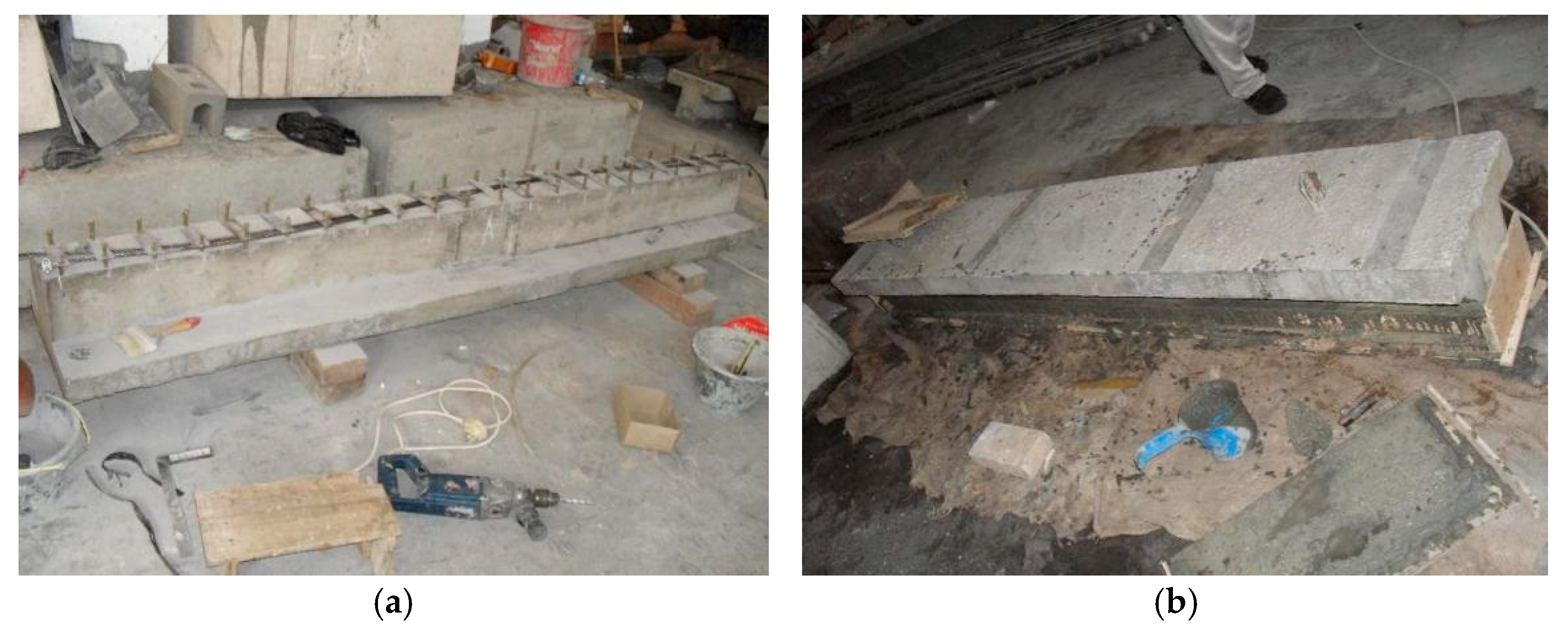
2.2. Strengthening Procedure

The strengthening procedure commenced with the non-invasive detection of existing reinforcement within the RC beam using a rebar scanner. Following this, precise drilling points were marked, ensuring that no direct contact was made with the embedded reinforcement during the subsequent dynabolt mounting process. Boreholes, each approximately 6 cm deep, were then drilled. The resulting cavities were thoroughly cleaned using compressed air to remove residual dust, after which a chemical bonding agent was injected to promote proper adhesion. Subsequently, the anchorage system—comprising a steel plate and dynabolt—was installed, and the procedure was completed by tightening the dynabolt at the upper section of the steel plates. Finally, to bond the FC-SWRs to the existing concrete surface, a mortar adhesive was applied.

2.3. Properties of Materials

The concrete mix was designed using cylindrical specimens with a height of 300 mm and a diameter of 150 mm. Compressive tests conducted at 28 days yielded an average compressive strength of 32.40 MPa, classifying it as normal concrete. In addition, Figure 2a shows that steel plates and dynabolts, each with a diameter of 8 mm and an average shear strength of 14.50 kN, were used to fasten and anchor the FC-SWRs. Moreover, as shown in Figure 2b, the adhesive used for bonding the FC-SWRs to the existing concrete was a mortar with an average compressive strength of 49.85 MPa.
An FC-SWR typically consists of several strands of steel wires helically wound around a central fiber core, which serves as the rope’s supporting structure. In this study, the core was made of synthetic fibers (polypropylene), and its primary functions were to provide flexibility, maintain the shape of the rope, and act as a reservoir for lubrication. Each strand within the rope is composed of multiple high-strength, cold-drawn steel wires twisted together in a specific lay pattern to form a strand. These strands are then twisted together around the fiber core in a helical fashion to complete the rope structure.
Meanwhile, the mechanical properties, including the ultimate strength and elastic modulus of the steel reinforcements and FC-SWR, were determined through tensile tests. The results, presented in Table 1, indicate the average values of yield strength (fy,m) and corresponding strain (εy,m), ultimate strength (fu,m) and corresponding strain (εu,m), and modulus of elasticity (E).

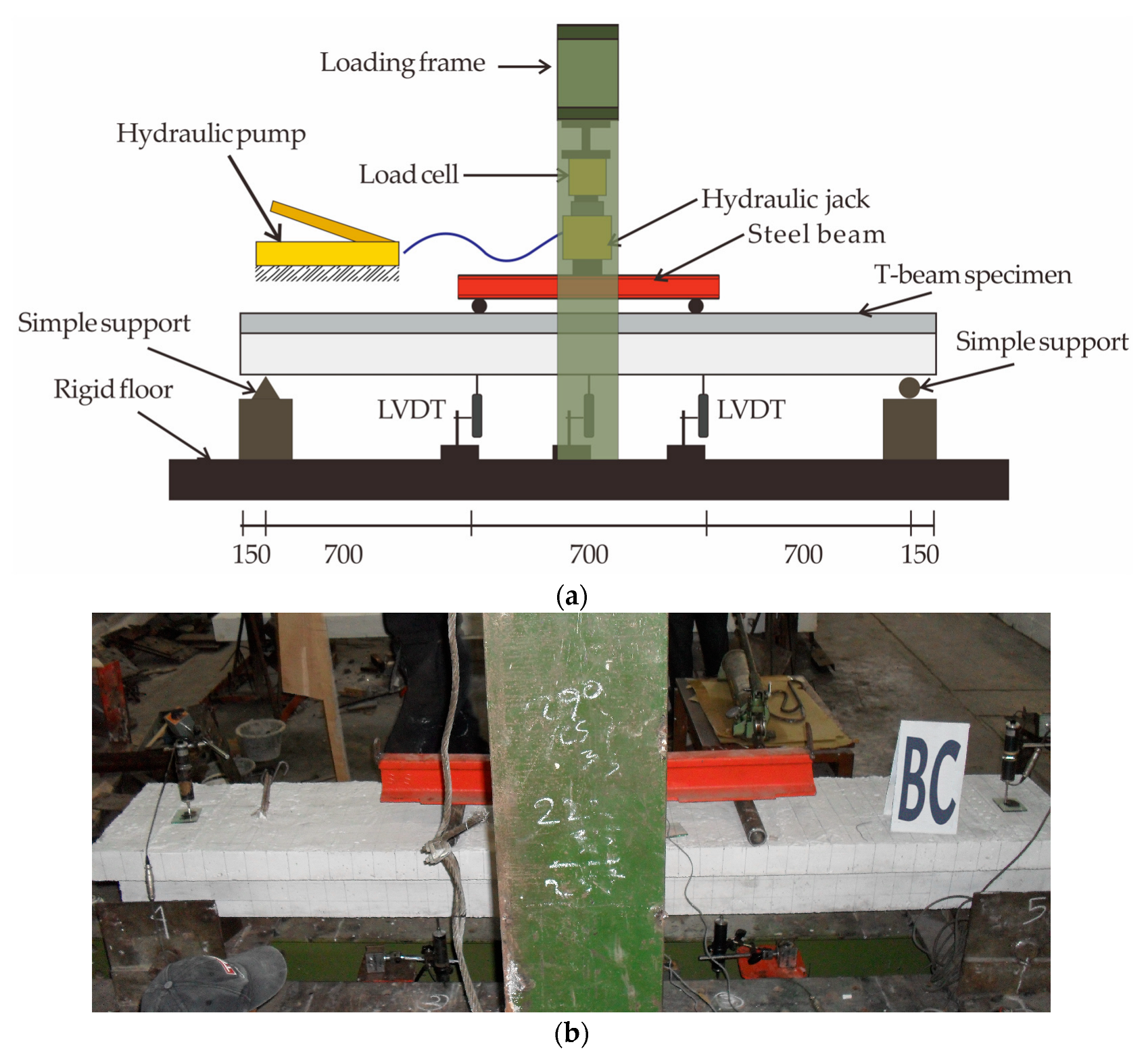
2.4. Testing Setup and Instrumentation

Figure 3 presents the test setup and instrumentation. The experimental investigation employed a four-point bending configuration, wherein a symmetric vertical load was introduced to the beam through a steel-section distribution beam. This configuration effectively created a constant moment zone spanning 700 mm at mid-span. The setup comprised, in descending order, a 1000 kN-capacity electro-hydraulic actuator, load cell, steel spreader beam, test specimen, and simple supports. A load control rate of 200 N/s was maintained throughout the test. During loading, crack development was carefully monitored, with crack positions and orientations marked using an ink pen for clarity. Concurrently, mid-span deflection was recorded via displacement sensors, and the strain in tensile steel reinforcements was measured using surface-mounted strain gauges.
Several critical response parameters were monitored during testing: applied load, vertical deflection, steel strain, and crack propagation behavior. Specifically, (1) the applied force was recorded using a calibrated pressure transducer; (2) vertical displacements were captured using three linear variable differential transformers (LVDTs), strategically positioned beneath the left loading point, mid-span, and right loading point; (3) tensile reinforcement strain was quantified using a 6 mm strain gauge affixed to the mid-length of the bottom steel bar; and (4) crack formation and growth were tracked visually with the aid of a crack monitoring viewer.

3. Results and Discussion

3.1. Flexural Load Carrying Capacity

The experimental values of load-carrying capacities are summarized in Table 2. The control beam (BC) exhibited a lower crack initiation load compared to the strengthened beam (BS). The application of bonded FC-SWRs increased the crack initiation load by approximately 40.00%, indicating enhanced resistance to early cracking. Although crack initiation is generally influenced by the compressive strength of the concrete, which remained consistent across all specimens, the observed increase was attributed to the additional tensile strength provided by the bonded FC-SWRs. This strengthening system effectively delayed the formation of initial cracks, improving the overall structural integrity of the beam under loading conditions.
A similar trend was observed for the yield and ultimate loads. The yield load of BS increased by 26.00% compared to BS, demonstrating an improvement in the beam’s elastic response before yielding. Additionally, the ultimate load capacity of BS was 72.00% higher than that of BC, highlighting the significant contribution of bonded FC-SWRs in enhancing the beam’s ability to sustain higher loads before failure. These results are consistent with the findings of Haryanto et al. [49], which demonstrated that the bonded system is an effective strengthening technique for improving both the serviceability and load-carrying capacity of RC beams.
This improvement is primarily attributed to the ability of FC-SWRs to act as additional tensile reinforcement in the tension zone. By providing an external force-carrying path, the FC-SWRs help redistribute tensile stresses more evenly along the bottom surface of the beam, thereby reducing localized stress concentrations that typically initiate cracking or premature failure. Stress concentration usually occurs in regions with abrupt changes in stiffness or where reinforcement is insufficient, leading to crack initiation. The continuous nature and bonding of FC-SWRs mitigate this by promoting better stress transfer and delaying crack propagation.

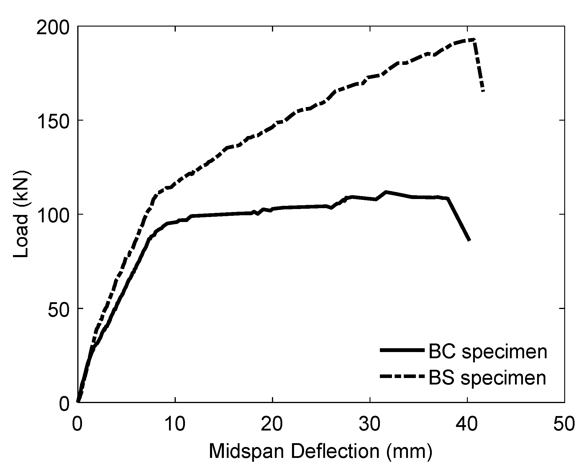
3.2. Load–Deflection Curves
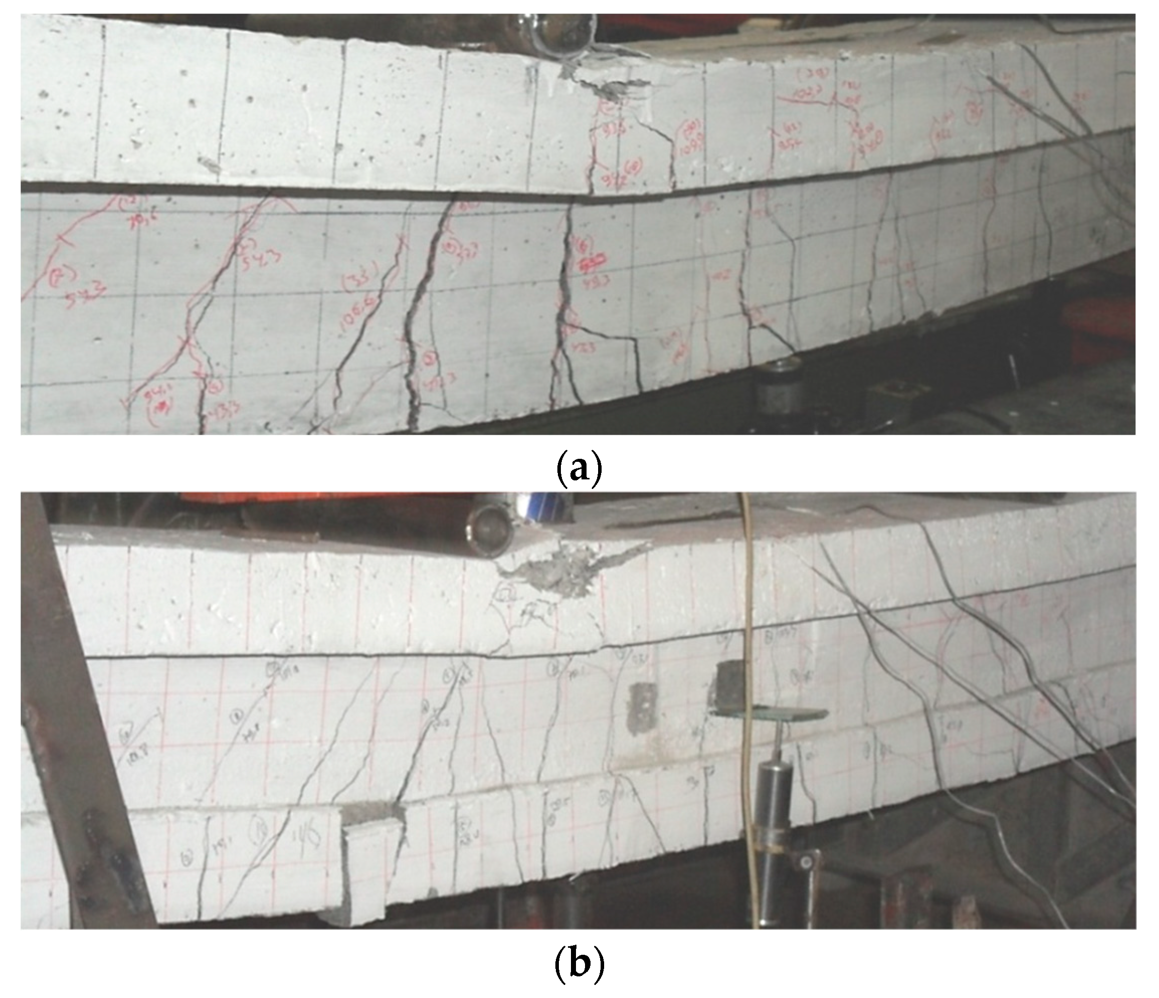
The load–deflection relationships for all beams are shown in Figure 4, where a trilinear model represents their behavior up to failure. This model captures the beam’s stiffness changes, cracking progression, and ultimate failure response under loading.
The first segment represents the initial stiffness phase, where the beam remains elastic, resisting deformation with a steep linear slope. The transition to the crack initiation stage marks the formation of the first visible cracks, reducing stiffness. The second segment, with a moderate slope, extends from crack propagation to yielding. As cracks increase, stiffness gradually declines, redistributing stress to the reinforcement. This phase is crucial in assessing the beam’s ductility and energy absorption. The third segment, with the lowest slope, represents the post-yielding phase, where the beam undergoes plastic deformations before reaching its ultimate load capacity. Since this phase determines ductility, it is key in evaluating structural performance. Additionally, the mid-span deflection at crack initiation load was found to be 24.00% higher in BS compared to BC, indicating that the strengthened beam can sustain higher deflections before crack formation, thereby enhancing their serviceability and long-term structural performance.
The yield load improvement for the strengthened beam has been discussed in the previous subsection, accompanied by a corresponding increase in mid-span deflection, as reflected in the second segment of the trilinear model. This phase represents the transition from crack propagation to yielding, where stiffness gradually decreases due to stress redistribution in the reinforcement. However, the deflection increase at yield was lower than that at crack initiation, with BS exhibiting only an 8.00% increase compared to the control specimen (BC). This suggests that while strengthening improves yield behavior, its effect on deflection during this phase remains moderate. The presence of bonded FC-SWRs helps delay excessive deformation but does not drastically alter mid-span deflection at yield. Additionally, the mid-span deflection at the ultimate load showed a 29.00% increase in the strengthened beam compared to the unstrengthened beam (BC). This significant enhancement indicates improved energy absorption capacity in the post-yielding phase, allowing the beam to sustain higher deformations before failure, which is crucial for structural resilience and ductility.

3.3. Failure Modes

Figure 5 illustrates the typical failure modes of the specimens. The control beam (BC) failed due to concrete crushing in the compression zone following the yielding of the steel reinforcement. Flexural cracks initially formed near the mid-span and later propagated through the full depth of the constant moment region, ultimately leading to failure. The first crack was observed at 28.20 kN, followed by multiple flexural cracks until 87.00 kN, which corresponded to the yield load of the steel reinforcement. Crack propagation extended through the entire section depth at 111.80 kN, causing the specimen to fail.
Flexural failure, similar to that of the control beam, was also observed in the strengthened beam (BS). However, differences were noted in crack initiation, yield, and ultimate load capacities. Several flexural cracks formed and propagated through the section depth, while minor shear cracks appeared near the loading point and supports. These shear cracks, however, did not contribute to the final failure of the specimen. The presence of bonded FC-SWRs enhanced the beam’s resistance, delaying crack propagation and increasing overall structural integrity compared to the unstrengthened specimen.

3.4. Ductility Index and Stiffness

Ductility refers to a structure’s ability to undergo inelastic deformation before failure without a significant loss in strength or resistance. This property is essential because it allows stress redistribution and provides an early warning of failure through gradual deflections. The ability of a reinforced member to deform progressively during the plastic stage is a key factor in reinforced concrete design. Additionally, a ductile structure exhibits robustness, enabling it to resist accidental loading from local impacts and effectively dissipate energy under cyclic loading, such as seismic events [51,52].
To quantify ductility in this study, the ductility index is computed at failure load using Equation (1):
I f = δ f δ y ,
where mid-span yield deflection (δy) serves as the reference benchmark. This allows for the evaluation of the effect of FC-SWRs in enhancing the ductility of the strengthened beam compared to the control beam in this study.
Another essential characteristic of RC structures is stiffness, which describes a beam’s ability to resist displacement under applied loads [53]. Stiffness is a key factor in ensuring serviceability, influencing crack formation and deflection behavior. The stiffness of RC beams is largely affected by applied loads, cracking patterns, and reinforcement configurations [54], including bonded FC-SWRs. In this study, stiffness was evaluated under two conditions: initial and yield stiffness. The initial stiffness, indicative of the beam’s uncracked elastic response, was quantified as the gradient of the load–deflection curve prior to the onset of the first visible flexural crack. In contrast, the yield-stage stiffness characterized the structural behavior during the transition from elastic to inelastic response and was determined from the slope of the curve between the occurrence of initial cracking and the yield point of the longitudinal reinforcement. Table 3 presents the ductility index and stiffness of the tested beams, highlighting the differences between the strengthened and control beams.
The failure ductility of the strengthened specimen (BS) was 4.00% lower than that of the control specimen. Previous research has shown that increasing reinforcement often leads to a reduction in ductile behavior [55] because additional reinforcement restricts deformation capacity, limiting the beam’s ability to undergo plastic deformation before failure. This suggests that, in this study, the inclusion of bonded FC-SWRs resulted in a slight decrease in ductility due to the higher tension reinforcement ratio, resulting in the loss of the yield plateau in the load–deflection curve, which is typically associated with ductile response.
Conversely, the stiffness of the strengthened specimen increased by 13.00% in terms of initial stiffness and 16.00% in yield stiffness compared to the control beam. In unstrengthened beams, internal steel reinforcement plays a key role in controlling crack growth, which directly affects stiffness [54]. However, in strengthened beams, the addition of FC-SWRs further restricts crack initiation and propagation, thereby leading to a greater increase in stiffness and improved overall structural performance.

3.5. Energy Absorption

Energy absorption is a key factor in evaluating the fracture work of a structural element and is typically measured as the area under the load–deflection curve [56]. Figure 6 presents the energy absorption levels for all specimens in this study, showing that the strengthened specimen exhibited higher values than the control specimen.
The bonded FC-SWRs enhanced energy absorption by 54.00%, primarily due to delayed crack formation, increased stiffness, and significant improvements in both yield and ultimate loads. The inclusion of bonded FC-SWRs strengthens the beam’s load-bearing capacity, allowing it to sustain higher loads over a longer displacement range. This delay in crack propagation prevents premature failure, enabling the beam to absorb more energy before collapse. Additionally, the increase in stiffness restricts excessive deflection, ensuring a more controlled failure mechanism.

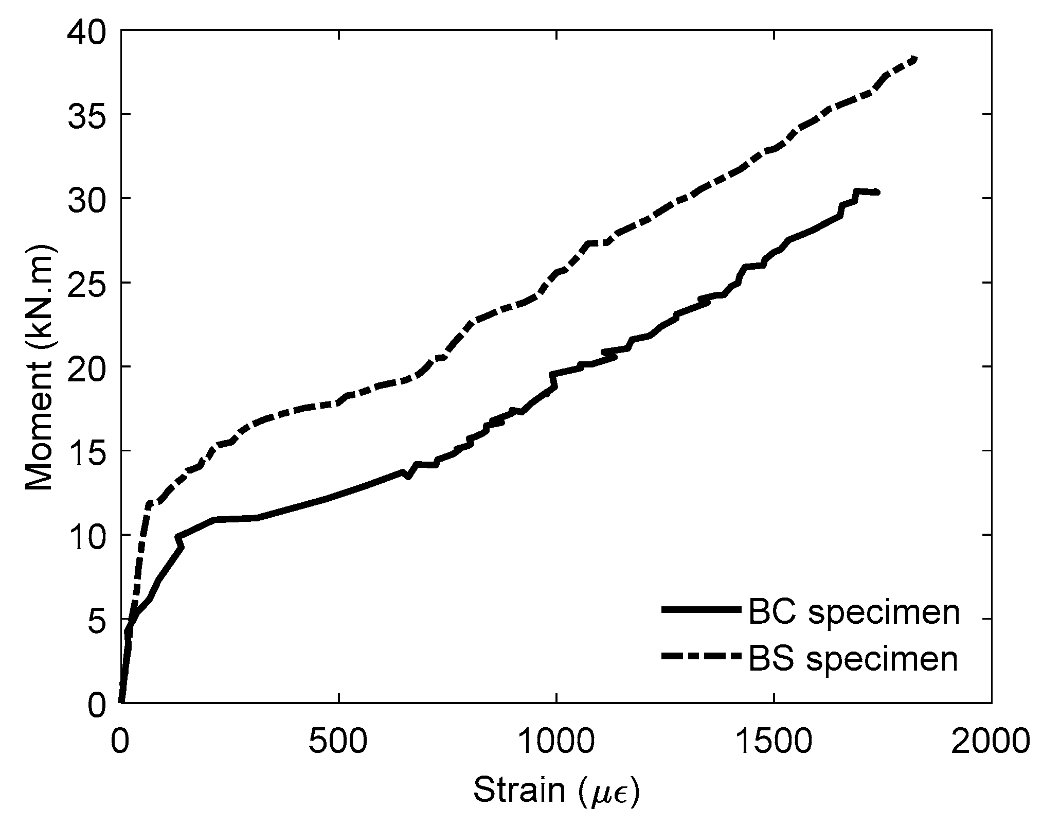
3.6. Steel Strain Response

The moment versus mid-span steel strain curves for the specimens are presented in Figure 7, showing that the strain variation trends in the longitudinal reinforcement of the BC were similar to those in the BS beam. However, the steel strain variation can be divided into three stages. At the initial stage, the strain values increased almost linearly with the applied load. However, after cracking, a decline in the curve’s slope was observed, indicating a reduction in stiffness. The steel strain values of the strengthened beam (BS) were consistently lower than those of the control beam (BC) at the same load levels.
For instance, at a bending moment of 15.00 kNm, the BC recorded 778 µε, whereas the BS beam recorded only 209 µε. A similar trend was observed at 25.00 kNm, where the BC exhibited 1417 µε, while the BS beam showed a lower strain of 973 µε. These observations indicate that the presence of FC-SWRs significantly influenced the strain distribution in the tension zone. By sharing the tensile demand, the FC-SWRs reduced stress on the steel bars and improved the beam’s flexural performance under load.
Unlike BC, where the steel bars alone resisted the tensile load, the BS beam distributed the load between the steel bars and FC-SWRs, reducing the strain in the reinforcement and enhancing structural performance. This composite action between the internal steel and external FC-SWRs improved the beam’s ability to control deformation under flexural loading.

4. Analytical Modeling

An analytical calculation was performed using Response-2000 (R2K), a computational program developed based on the Modified Compression Field Theory (MCFT) [57]. This method is widely recognized for its efficiency and reliability in predicting the nonlinear behavior of RC elements under various loading conditions. It has been extensively validated through experimental studies and is known for its ability to accurately estimate responses in flexural and shear-critical members [58,59,60,61].

4.1. Constitutive Laws

The analytical models developed using R2K incorporated the nonlinear behavior of concrete in compression. To enhance this approach, strain-stress relationships formulated by Popovics [62] and Porasz [63] were integrated through Equations (2)–(4) to refine the model. In this context, f c denotes the concrete compressive stress in MPa corresponding to a given strain value ε c , f c   represents the concrete compressive strength in MPa, E c   signifies the concrete modulus of elasticity in MPa, ε c 0 defines the strain at peak compressive strength, n serves as the curve-fitting parameter, and k accounts for the reduction in post-peak ductility in high-strength concrete. Moreover, Equation (5) was utilized to incorporate the model proposed by Bentz [57], which characterizes the nonlinear material properties of concrete in tension (ft) and was implemented in R2K.
f c = ε c ε c o f c n n 1 + ε c / ε c o n k  
n = 0.8 + f c 17
k = 1.0 i f ε c ε c o < 1.0 0.67 + f c 62 i f ε c ε c o > 1.0
f t = 0.45 f c 0.4
The stress–strain response of steel reinforcement typically consists of three fundamental stages: an initial linear-elastic response, a yield plateau, and either a linear or nonlinear strain-hardening phase leading up to rupture. This monotonic stress–strain curve serves as the backbone for the hysteretic response models developed by Seckin [64] and Menegotto and Pinto [65]. Additionally, Equation (6) defines the steel reinforcement stress (fs) in both tension and compression.
f s = E s ε s for ε s < ε y f y for ε y < ε s ε s h f u + f y f u ε u ε s ε u ε s h P for ε s h < ε s ε u 0 for ε u < ε s ,
where   ε s represents the reinforcement strain ( ε s = ε s ) , ε y corresponds to the yield strain, ε s h denotes the strain at the onset of strain hardening, ε u signifies the ultimate strain, E s is the elastic modulus, f y represents the yield strength, f u is the ultimate strength, and P is the strain-hardening parameter. There are two possible strain-hardening phases after the yield plateau: linear strain-hardening (trilinear, P = 1 ) and nonlinear strain-hardening ( P = 4 ), both of which were assigned to the analytical models developed in R2K. The strain-hardening modulus, which governs the material’s behavior beyond yielding, was defined using Equation (7).
E s h = f u f y ε u ε s h
The FC-SWR stress–strain response implemented in R2K was modeled based on the behavior of cold-worked steel reinforcement, which lacks a distinct yield phase. Instead, its response was characterized by an initial linear-elastic branch, followed by a smooth transition curve leading to a second strain-hardening linear branch. To accurately capture this behavior, the Ramsberg–Osgood formulation [66] was applied using Equations (8)–(10) to determine the FC-SWR stress ( f s ) in tension. In this approach, E s represents the initial elastic modulus, ε s denotes the reinforcement strain, f u is the ultimate strength, and f s *   is the stress-axis intercept at zero strain for the second linear branch.
f s = E s ε s A + 1 A 1 + B ε s C 1 C f u  
A = E s h E s
B = E s 1 A f s *
Additionally, a transition coefficient (C) with a representative value of 10 for low-relaxation steel was adopted to approximate the tensile response of FC-SWR, based on the uniaxial tension test results shown in Figure 8. This ensured an accurate depiction of the material’s behavior under loading.

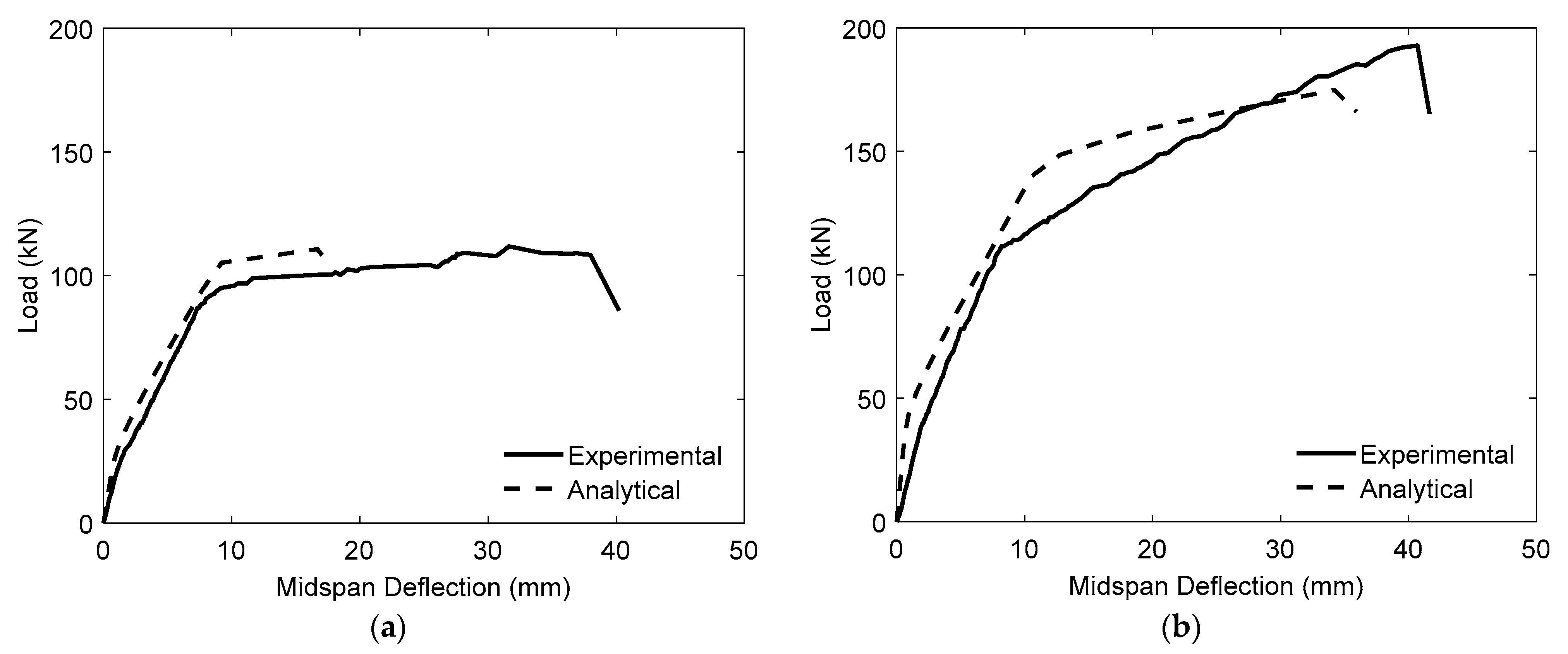
4.2. Model Validation

The two tested specimens were modeled and analyzed to validate the analytical model’s accuracy. Following this, the predictions generated by the R2K program were compared with the experimental data. The experimental and predicted load versus mid-span deflection results across all loading stages are presented in Figure 9, while Table 4 provides a comparison of the ultimate attained load (Pu) values and the corresponding Pu,Exp/Pu,Ana ratio between the two methods.
Figure 9 demonstrates that the predicted responses closely replicate the experimental responses, capturing key behavioral trends. The analytical model effectively predicts the initial linear-elastic phase, followed by a transitional nonlinear phase, and a reasonably linear response up to the peak load. This agreement is particularly noteworthy given the complexity of the actual response, where the formation of new cracks and the propagation of pre-existing ones lead to a gradual reduction in overall beam stiffness. This suggests that the model is capable of capturing the essential characteristics of RC beam behavior under flexural loading.
However, the analytical model exhibited some limitations near the peak load, where it tended to underestimate beam ductility. Despite this, the normalized mean square error (NMSE) for load capacity prediction was calculated as 0.007, which is considered acceptable from a design perspective. These results indicate that the developed analytical model can be effectively utilized in design-oriented parametric studies to examine the influence of FC-SWR diameter, FC-SWR modulus of elasticity, and steel reinforcement ratio on the performance of beams strengthened using the bonded technique.

4.3. Parametric Study

4.3.1. Effect of FC-SWR Diameter

The behavior of beams with varying FC-SWR diameters was investigated using four analytical models—one unstrengthened control and three strengthened specimens, each incorporating two bonded FC-SWRs with diameters of 6 mm, 8 mm, and 10 mm. In this parametric study, B-01 denotes the control specimen, while B-02, B-03, and B-04 represent the beams strengthened with FC-SWRs of 6 mm, 8 mm, and 10 mm, respectively, and 1.2% steel reinforcement ratio. All models were analyzed using a concrete compressive strength of 25.00 MPa, mortar compressive strength of 45.00 MPa, an FC-SWR modulus of elasticity of 35,725 MPa, and a steel reinforcement ratio (ρ) of 1.2%. The predicted load–deflection response curves for each model are presented in Figure 10.
Additionally, the designation of each model, along with a summary and comparison of the predicted ultimate attained load (Pu) and the corresponding mid-span deflection (δu), is presented in Table 5. Both Figure 10 and Table 5 indicate that the beams strengthened with bonded FC-SWRs exhibited greater flexural strength and load-carrying capacity compared to the unstrengthened beam (B-01). This is particularly evident in the Pu values, where B-02, strengthened with a 6 mm FC-SWR diameter, demonstrated a 25.00% increase over B-01. Similarly, B-03, with an 8 mm FC-SWR diameter, showed a 39.00% increase, while B-04, incorporating a 10 mm FC-SWR diameter, exhibited the highest improvement at 50.00%.
The progressive increase in load-carrying capacity with larger FC-SWR diameters highlights a direct relationship between beam strength enhancement and FC-SWR size. As the diameter increases, the cross-sectional area and stiffness of the FC-SWRs also increase, which helps delay crack initiation and improve overall flexural behavior. This results in greater tensile force capacity, leading to enhanced load resistance and improved structural performance.

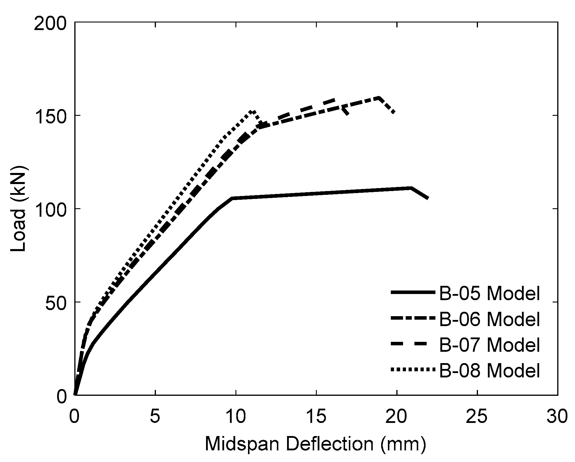
4.3.2. Effect of FC-SWR Modulus of Elasticity

The effect of the modulus of elasticity of FC-SWR materials on the structural performance of the specimens was examined by developing and analyzing four models. One served as the control specimen (B-05), while the remaining three were strengthened with two 8 mm-diameter FC-SWRs possessing 50%, 60%, and 100% of the elastic modulus of steel reinforcement, designated as B-06, B-07, and B-08, respectively. All models had concrete and mortar compressive strengths of 27.00 MPa and 40.00 MPa, respectively, and a steel reinforcement ratio (ρ) of 1.2%. The designation of the specimens, along with the expected ultimate load capacity (Pu) and corresponding mid-span deflection (δu) results, is summarized in Figure 11 and Table 6.
Figure 11 shows that all models exhibited similar behavior prior to steel yielding; however, after this point, the beams strengthened with FC-SWRs demonstrated distinct responses depending on variations in their elastic modulus, which directly influenced their deformation behavior. As indicated in Table 6, the specimens strengthened with bonded FC-SWRs experienced a reduction in δu by 10.00%, 23.00%, and 47.00% for B-06, B-07, and B-08, respectively, compared to the control beam (B-05).
A substantial reduction in ductility—particularly in beam B-08—was attributed to highly localized strain concentrations near the compression zone. The elevated compressive strain values observed at the top fiber signaled the onset of concrete crushing before significant flexural deformation could develop. This behavior indicates a brittle failure mode in beam B-08, primarily caused by the excessive stiffness of the external reinforcement, which limited strain redistribution and led to premature crushing on the compression side. Such findings illustrate a common trade-off in over-strengthened systems: while load-carrying capacity increases, ductility tends to decrease.
These results suggest that bonded FC-SWRs with a higher modulus of elasticity, when used as a strengthening material, tend to reduce the ductility of the strengthened specimens. A similar inverse relationship was reported by Hawileh [67], who observed a decrease in ductility with increasing elastic modulus. Although both studies confirm this trend, they differ in the types of strengthening materials applied to the test specimens.

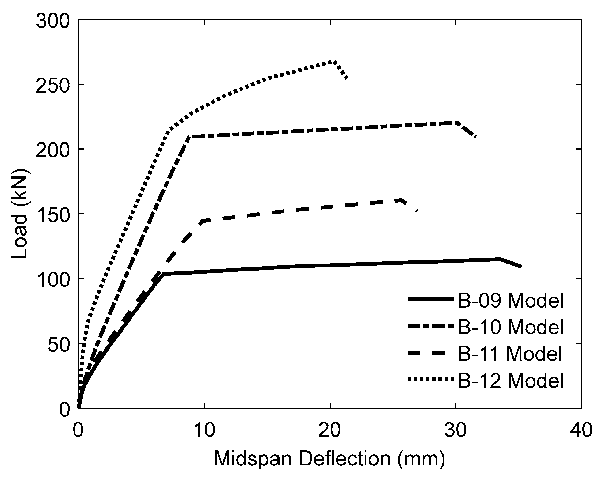
4.3.3. Effect of Steel Reinforcement Ratio

To assess the influence of steel reinforcement ratio (ρ) on the structural behavior of the specimens, four analytical models were developed. Two of these models served as unstrengthened references, while the remaining two incorporated two bonded FC-SWRs with a diameter of 10 mm. The longitudinal steel reinforcement was varied by altering the bar configuration: 3D13 (ρ = 1.2%) for models B-09 and B-11, as well as 3D19 (ρ = 2.7%) for B-10 and B-12. Each reinforcement arrangement was examined in both unstrengthened and strengthened conditions to capture the comparative effects. All analyses assumed a concrete compressive strength of 20.00 MPa, a mortar compressive strength of 50.00 MPa, and an FC-SWR elastic modulus of 35,725 MPa. Figure 12 exhibits the predicted load–deflection response curves for each model.
Additionally, Table 7 outlines the model identifiers alongside a comparative summary of the predicted ultimate load capacity (Pu) and corresponding mid-span deflection (δu). As illustrated in both Table 7 and Figure 12, beams with a steel reinforcement ratio of 1.2%—classified as under-reinforced—exhibited a substantial enhancement in ultimate strength, with an increase of 39.62% relative to the control specimen. This improvement demonstrates the significant contribution of bonded FC-SWRs when the internal reinforcement is insufficient to resist flexural tension alone. The added tensile capacity from the FC-SWRs compensates for the lower steel ratio, effectively delaying failure and increasing load resistance. In contrast, specimens categorized as over-reinforced, having a steel ratio of 2.7%, demonstrated a more modest improvement of 21.56%.
In contrast, specimens categorized as over-reinforced, having a steel ratio of 2.7%, demonstrated a more modest improvement of 21.56%. This reduced gain in flexural strength for over-reinforced beams can be attributed to the dominant role of internal reinforcement, which diminishes the relative contribution of the external FC-SWRs. As the failure mode shifts toward compression-controlled behavior, the effectiveness of tensile strengthening becomes less pronounced. Moreover, the redistribution of tensile stresses in heavily reinforced sections is already optimized by the existing steel, leaving limited room for the FC-SWRs to improve performance. These findings suggest that the bonded FC-SWR technique is most beneficial for retrofitting under-reinforced beams, where its contribution to flexural capacity is more structurally impactful.

5. Conclusions

This study investigated the flexural performance of RC T-beams strengthened with bonded FC-SWRs. A four-point bending test was conducted on two specimens: one served as the control beam, while the other was strengthened with two 10 mm-diameter bonded FC-SWRs. The experimental results were then verified analytically, leading to the following key findings:
  • Flexural strengthening of RC T-beams with bonded SWRs proved to be effective, as demonstrated by the increase in crack initiation, yield, and ultimate loads. Although the mode of failure remained flexural for both the strengthened and unstrengthened specimens, the strengthened beam exhibited higher load capacities at each stage of failure, highlighting the contribution of bonded SWRs in enhancing structural performance.
  • The strengthened beam exhibited increased stiffness due to the additional reinforcement, which restricted crack initiation and propagation; however, this also led to a decrease in ductility by limiting its deformation capacity.
  • The energy absorption capacity of the strengthened beam improved compared to the control beam, primarily due to delayed crack formation, increased stiffness, and enhanced yield and ultimate loads.
  • The steel strain values in the strengthened beam were consistently lower than those in the control beam at the same load levels, indicating improved load distribution. This reduction in strain suggests that the bonded FC-SWRs effectively transferred tensile stresses.
  • The analytical models successfully simulated the flexural behavior of the RC T-beam specimens, with and without bonded FC-SWRs, demonstrating good agreement with experimental results.
  • The increase in load-carrying capacity was directly proportional to the increase in FC-SWR diameter, confirming a size-dependent strengthening effect.
  • The use of bonded FC-SWRs with a higher modulus of elasticity reduced ductility, highlighting the trade-off between strength enhancement and deformation capacity.
  • The effectiveness of bonded FC-SWRs was more prominent in under-reinforced beams, which showed greater flexural strength gains than over-reinforced specimens.
  • Despite offering valuable insights, this study is limited by the small number of specimens. Future work should involve a broader test matrix to improve statistical validity.

Author Contributions

Conceptualization, A.T.A. and Y.H.; methodology, A.T.A. and Y.H.; software, A.T.A. and Y.H.; validation, A.T.A., Y.H., F.-P.H., H.-T.H., and L.N.; formal analysis, A.T.A., Y.H., and L.N.; investigation, A.T.A., Y.H., F.-P.H., and H.-T.H.; resources, A.T.A.; data curation, A.T.A. and Y.H.; writing—original draft preparation, A.T.A., Y.H., and L.N.; writing—review and editing, A.T.A., Y.H., F.-P.H., H.-T.H., and L.N.; visualization, Y.H. and L.N.; supervision, Y.H.; project administration, A.T.A. All authors have read and agreed to the published version of the manuscript.

Funding

This research received no external funding.

Data Availability Statement

All data and models supporting the findings of this study are available from the corresponding author(s) upon reasonable request. The data are not publicly available due to privacy concerns and the confidentiality of ongoing research.

Acknowledgments

The authors sincerely appreciate the anonymous reviewers for their valuable comments and suggestions, which have contributed to improving the quality of this paper.

Conflicts of Interest

The authors declare no conflicts of interest.

Abbreviations

The following abbreviations are used in this manuscript:
RCReinforced concrete
FRPFiber-reinforced polymer
NSMNear-surface mounted
CFRPCarbon fiber-reinforced polymer
HSCHigh-strength concrete
SWRSteel wire rope
FC-SWRFiber-core steel wire rope
LVDTLinear Variable Differential Transducers
R2KResponse-2000
MCFTModified Compression Field Theory

References

  1. Turki, A.Y.; Al-Farttoosi, M.H. Flexural Strength of damaged RC beams repaired with carbon fiber-reinforced polymer (CFRP) using different techniques. Fibers 2023, 11, 61. [Google Scholar] [CrossRef]
  2. Rizwan, M.; Ahmad, N.; Khan, A.N. Seismic performance of RC frame having low strength concrete: Experimental and numerical studies. Earth Struct. 2019, 17, 75–89. [Google Scholar]
  3. Pei, Q.; Cai, B.; Xue, Z.; Ding, Y.; Cui, D.; Guo, Y. Study on mechanical properties of corroded concrete columns strengthened with SMA wires. PLoS ONE 2023, 18, e0276280. [Google Scholar] [CrossRef] [PubMed]
  4. Pei, Q.; Zhong, Y.; Wang, B.; Qi, P.; Xue, Z.; Cui, D.; Ding, Y.; Cai, B. Performance of SRC unequal-depth beam-column irregular joint in NPP under progressive collapse. Structures 2024, 70, 107593. [Google Scholar] [CrossRef]
  5. Al-Mosawe, D.; Neves, L.; Owen, J. Reliability analysis of deteriorated post-tensioned concrete bridges: The case study of Ynys-y-Gwas bridge in UK. Structures 2022, 41, 242–259. [Google Scholar] [CrossRef]
  6. Jiang, X.; Cao, D.Q.; Qiang, X.H.; Xu, C.L. Study on fatigue performance of steel bridge welded joints considering initial defects. J. Constr. Steel Res. 2024, 212, 108309. [Google Scholar] [CrossRef]
  7. Franco, N.; Biscaia, H.; Chastre, C. Experimental and numerical analyses of flexurally-strengthened concrete T-beams with stainless steel. Eng. Struct. 2018, 172, 981–996. [Google Scholar] [CrossRef]
  8. Tehrani, B.N.; Mostofinejad, D.; Hosseini, S.H. Experimental and analytical study on flexural strengthening of RC beams via prestressed EBROG CFRP plates. Eng. Struct. 2019, 197, 109395. [Google Scholar] [CrossRef]
  9. Sabzi, J.; Esfahania, M.R.; Ozbakkaloglu, T.; Farahic, B. Effect of concrete strength and longitudinal reinforcement arrangement on the performance of reinforced concrete beams strengthened using EBR and EBROG methods. Eng. Struct. 2020, 205, 110072. [Google Scholar] [CrossRef]
  10. Moshiri, N.; Czaderski, C.; Mostofinejad, B.; Motavalli, M. Bond resistance of prestressed CFRP strips attached to concrete by using EBR and EBROG strengthening methods. Constr. Build. Mater. 2021, 266, 121209. [Google Scholar] [CrossRef]
  11. Nugroho, L.; Haryanto, Y.; Hu, H.-T.; Hsiao, F.-P.; Pamudji, G.; Setiajdi, B.H.; Hsu, C.-N.; Weng, P.-W.; Lin, C.-C. Prestressed concrete T-beams strengthened with near-surface mounted carbon-fiber-reinforced polymer rods under monotonic loading: A finite element analysis. Eng 2025, 6, 36. [Google Scholar] [CrossRef]
  12. Lam, L.; Teng, J.G. Stress–strain model for FRP-confined concrete under cyclic axial compression. Eng. Struct. 2009, 31, 308–321. [Google Scholar]
  13. Hui, C.; Li, Y.; Zhao, Z.; Hai, R. Behavior of concrete-filled GFRP tube columns under cyclic axial compression. Constr. Build. Mater. 2021, 294, 123566. [Google Scholar]
  14. Lin, C.T.; Wu, Y.H.; Chin, W.H.; Lin, M.L. Performance of CFRP-strengthened RC beams subjected to repeated loads. J. Chin. Inst. Eng. 2014, 37, 1007–1017. [Google Scholar]
  15. Lee, D.H.; Han, J.S.; LaFave, J.M. Shear strength of reinforced concrete beams strengthened in shear using externally-bonded FRP composites. Compos. Struct. 2017, 173, 177–187. [Google Scholar] [CrossRef]
  16. Irshidat, M.R.; Al-Shannaq, A. Using textile reinforced mortar modified with carbon nano tubes to improve flexural performance of RC beams. Compos. Struct. 2018, 200, 127–134. [Google Scholar] [CrossRef]
  17. Karayannis, C.G. Golias, Full scale tests of RC joints with minor to moderate seismic damage repaired using CFRP sheets. Earthq. Struct. 2018, 15, 617–627. [Google Scholar]
  18. Liao, J.; Zeng, J.-J.; Zhuge, Y.; Ma, G.; Zhang, L. FRP-confined concrete columns with a stress reduction-recovery behavior: A state-of-the-art review, design recommendations and model assessments. Compos. Struct. 2023, 321, 117313. [Google Scholar] [CrossRef]
  19. Spinella, N.; Colajanni, P.; Recupero, A.; Tondolo, F. Ultimate shear of RC beams with corroded stirrups and strengthened with FRP. Buildings 2019, 9, 34. [Google Scholar] [CrossRef]
  20. Abdallah, M.; Al Mahmoud, F.; Khelil, A.; Mercier, J.; Almassri, B. Assessment of the flexural behavior of continuous RC beams strengthened with NSM-FRP bars, experimental and analytical Study. Compos. Struct. 2020, 242, 112127. [Google Scholar]
  21. Giese, A.C.H.; Giese, D.N.; Dutra, V.F.P.; Filho, L.C.P.D.S. Flexural behavior of reinforced concrete beams strengthened with textile reinforced mortar. J. Build. Eng. 2021, 33, 101873. [Google Scholar] [CrossRef]
  22. Haryanto, Y.; Wariyatno, N.G.; Hsiao, F.-P.; Hu, H.-T.; Han, A.L.; Nugroho, L.; Hartono, H. RC T-beams with flexural strengthening in the negative moment region under different configurations of NSM CFRP rods. Eng. Fail. Anal. 2025, 173, 109458. [Google Scholar] [CrossRef]
  23. Han, A.L.; Hu, H.-T.; Gan, B.S.; Hsiao, F.-P.; Haryanto, Y. Carbon fiber-reinforced polymer rod embedment depth influence on concrete strengthening. Arab. J. Sci. Eng. 2022, 47, 12685–12695. [Google Scholar]
  24. Haryanto, Y.; Hsiao, F.-P.; Hu, H.-T.; Han, A.L.; Chua, A.W.; Salim, F.; Nugroho, L. Structural behavior of negative moment region NSM-CFRP strengthened RC T-beams with various embedment depth under monotonic and cyclic loading. Compos. Struct. 2022, 301, 116214. [Google Scholar]
  25. Haryanto, Y.; Hermanto, N.I.S.; Hsiao, F.-P.; Hu, H.-T.; Han, A.L.; Nugroho, L.; Salim, F. Predicting the behavior of RC T-beams strengthened with NSM-CFRP rods in the negative moment region: A finite element approach for low cyclic loading. E3S Web Conf. 2023, 464, 06001. [Google Scholar]
  26. Nugroho, L.; Haryanto, Y.; Hu, H.-T.; Han, A.L.; Hsiao, F.-P.; Lin, C.-C.; Weng, P.-W.; Widiastuti, E.P. NSM-CFRP rods with varied embedment depths for strengthening RC T-beams in the negative moment region: Investigation on high cyclic response. Compos. Struct. 2024, 331, 117891. [Google Scholar]
  27. Emara, M.; Salem, M.A.; Mohamed, H.A.; Shehab, H.A.; El-Zohairy, A. Shear strengthening of reinforced concrete beams using engineered cementitious composites and carbon fiber-reinforced polymer sheets. Fibers 2023, 11, 98. [Google Scholar] [CrossRef]
  28. Mussa, M.H.; Mutalib, A.A.; Hao, H. Experimental and numerical study of carbon fibre-reinforced polymer-strengthened reinforced concrete beams under static and impact loads. Fibers 2024, 12, 63. [Google Scholar] [CrossRef]
  29. Alasmari, H.A.; Sharaky, I.A.; Elamary, A.S.; El-Zohairy, A. Rehabilitation and strengthening of damaged reinforced concrete beams using carbon fiber-reinforced polymer laminates and high-strength concrete integrating recycled tire steel fiber. Fibers 2025, 13, 10. [Google Scholar] [CrossRef]
  30. Elsanadedy, H.M.; Almusallam, T.H.; Alsayed, S.H.; Al-Salloum, Y.A. Flexural strengthening of RC beams using textile reinforced mortar—Experimental and numerical study. Compos. Struct. 2013, 97, 40–55. [Google Scholar]
  31. Ueda, T.; Dai, J. Interface bond between FRP sheets and concrete substrates: Properties, numerical modeling and roles in member behaviour. Prog. Struct. Eng. Mat. 2004, 7, 27–43. [Google Scholar] [CrossRef]
  32. Amran, Y.H.M.; Alyousef, R.; Rashid, R.S.M.; Alabduljabbar, H.; Hung, C.-C. Properties and applications of FRP in strengthening RC structures: A review. Structures 2018, 16, 208–238. [Google Scholar] [CrossRef]
  33. Chang, X.-d.; Huang, H.-b.; Peng, Y.-x.; Li, S.-x. Friction, wear and residual strength properties of steel wire rope with different corrosion types. Wear 2020, 458–459, 203425. [Google Scholar] [CrossRef]
  34. Kim, S.Y.; Yang, K.H.; Byun, H.Y.; Ashour, A.F. Tests of reinforced concrete beams strengthened with wire rope units. Eng. Struct. 2007, 29, 2711–2722. [Google Scholar] [CrossRef]
  35. Yang, K.H.; Ashour, A.F. Tests of reinforced concrete short columns laterally strengthened with wire rope units and steel elements. Mag. Concr. Res. 2007, 59, 547–557. [Google Scholar] [CrossRef]
  36. Yang, K.H.; Ashour, A.F.; Lee, E.T. Axial behavior of reinforced concrete short columns strengthened with wire rope and T-shaped steel plate units. Mag. Concr. Res. 2009, 61, 143–154. [Google Scholar] [CrossRef]
  37. Yang, K.H.; Byun, H.Y.; Ashour, A.F. Shear strengthening of continuous reinforced concrete T-beams using wire rope units. Eng. Struct. 2009, 31, 1154–1165. [Google Scholar] [CrossRef]
  38. Yang, K.H.; Joo, D.B.; Sim, J.I.; Kang, J.H. In-plane seismic performance of unreinforced masonry walls strengthened with unbonded prestressed wire rope units. Eng. Struct. 2012, 45, 449–459. [Google Scholar] [CrossRef]
  39. Li, K.; Wei, Y.; Li, Y.; Li, Z.; Zhu, J. Flexural behavior of reinforced concrete beams strengthened with high-strength stainless steel wire rope meshes reinforced ECC. Constr. Build. Mater. 2013, 362, 129627. [Google Scholar] [CrossRef]
  40. Wu, G.; Wu, Z.S.; Jiang, J.B.; Tian, Y.; Zhang, M. Experimental study of RC beams strengthened with distributed prestressed high-strength steel wire rope. Mag. Concr. Res. 2010, 62, 253–265. [Google Scholar] [CrossRef]
  41. Wu, G.; Wu, Z.S.; Wei, Y.; Jiang, J.B.; Cui, Y. Flexural strengthening of RC beams using distributed prestressed high strength steel wire rope: Theoretical analysis. Struct. Infrastruct. Eng. 2014, 10, 160–174. [Google Scholar] [CrossRef]
  42. Wei, Y.; Wu, Y.F. Compression behavior of concrete columns confined by high strength steel wire. Constr. Build. Mater. 2014, 54, 443–453. [Google Scholar] [CrossRef]
  43. JGJ/T 325-2014; Technical Specification for Strengthening Concrete Structures with Prestressed High Strength Steel Wire Ropes. General Administration of Quality Supervision, Inspection and Quarantine of the People’s Republic of China: Beijing, China, 2014. (In Chinese)
  44. Haryanto, Y.; Gan, B.S.; Widyaningrum, A.; Wariyatno, N.G.; Fadli, A. On the performance of steel wire rope as the external strengthening of RC beams with different end-anchor type. J. Teknol. 2018, 80, 145–154. [Google Scholar] [CrossRef]
  45. Haryanto, Y.; Han, A.L.; Hu, H.-T.; Hsiao, F.-P.; Hidayat, B.A.; Widyaningrum, A. Enhancement of flexural performance of RC beams with steel wire rope by external strengthening technique. J. Chin. Inst. Eng. 2021, 44, 193–203. [Google Scholar] [CrossRef]
  46. Sudibyo, G.H.; Haryanto, Y.; Hsiao, F.-P.; Hu, H.-T.; Nugroho, L.; Pamudji, G.; Widyaningrum, A.; Nugroho, P.S. Three-dimensional finite element analysis of externally strengthened RC bemas in flexure with SWR. Lect. Notes Civ. Eng. 2025, 625, 267–275. [Google Scholar]
  47. Li, X.; Wu, G.; Popal, M.S.; Jiang, J. Experimental and numerical study of hollow core slabs strengthened with mounted steel bars and prestressed steel wire ropes. Constr. Build. Mater. 2018, 188, 456–469. [Google Scholar] [CrossRef]
  48. Miao, W.; Guo, Z.-X.; Ye, Y.; Basha, S.H.; Liu, X.-J. Flexural behavior of stone slabs strengthened with prestressed NSM steel wire ropes. Eng. Struct. 2020, 222, 111046. [Google Scholar] [CrossRef]
  49. Haryanto, Y.; Sudibyo, G.H.; Nugroho, L.; Hu, H.-T.; Han, A.L.; Hsiao, F.-P.; Widyaningrum, A.; Susetyo, Y. Flexural performance of the negative moment region in bonded steel-wire-rope-strengthened reinforced concrete T-beams at different prestressing levels. Adv. Struct. Eng. 2024, 27, 2338–2358. [Google Scholar] [CrossRef]
  50. ACI Committee 318; Building Code Requirements for Structural Concrete and Commentary (ACI 318-19). American Concrete Institute: Farmington Hills, MI, USA, 2019.
  51. Morais, M.; Burgoyne, C. Energy Dissipation in Sections Prestressed with FRP Tendons. In Proceedings of the International Conference on Composites in Construction (CCC 2001), Porto, Portugal, 10–12 October 2001; Lisse: Exton, PA, USA; pp. 421–426. [Google Scholar]
  52. Li, C.; Aoude, H. Effect of UHPC jacketing on the shear and flexural behaviour of high-strength concrete beams. Structures 2023, 51, 1972–1996. [Google Scholar] [CrossRef]
  53. Obaydullah, M.; Jumaat, M.Z.; Alengaram, U.J.; Darain, K.M.U.; Huda, M.N.; Hosen, M.A. Prestressing of NSM steel strands to enhance the structural performance of prestressed concrete beams. Constr. Build. Mater. 2016, 129, 289–301. [Google Scholar] [CrossRef]
  54. Hosen, M.A.; Jumaat, M.Z.; Alengaram, U.J.; Sulong, H.N.R. CFRP strips for enhancing flexural performance of RC beams by SNSM strengthening technique. Constr. Build. Mater. 2018, 165, 28–44. [Google Scholar] [CrossRef]
  55. Rasheed, H.A.; Harrison, R.R.; Peterman, R.J.; Alkhrdaji, T. Ductile strengthening using externally bonded and near surface mounted composite systems. Compos. Struct. 2010, 92, 2379–2390. [Google Scholar] [CrossRef]
  56. Qeshta, I.M.I.; Shafigh, P.; Jumaat, M.Z.; Abdulla, A.I.; Ibrahim, Z.; Alengaram, U.J. The use of wire mesh-epoxy composite for enhancing the flexural performance of concrete beams. Mater. Des. 2014, 60, 250–259. [Google Scholar] [CrossRef]
  57. Bentz, E.C. Sectional Analysis of Reinforced Concrete Members. Ph.D. Thesis, University of Toronto, Toronto, ON, Canada, 2000. [Google Scholar]
  58. Lam, N.; Wilson, J.; Lumantarna, E. Force-deformation behavior modelling of cracked reinforced concrete by EXCEL spreadsheets. Comput. Concr. 2011, 8, 43–57. [Google Scholar] [CrossRef]
  59. Metwally, I.M. Evaluate the capability and accuracy of Response-2000 program in prediction of the shear capacities of reinforced and prestressed concrete members. HBRC J. 2012, 8, 99–106. [Google Scholar] [CrossRef]
  60. Suryanto, B.; Morgan, R.; Han, A.L. Predicting the response of shear-critical reinforced concrete beams using Response-2000 and SNI 2847:2013. Civ. Eng. Dimens. 2016, 8, 16–24. [Google Scholar]
  61. Huang, Z.; Tu, Y.; Meng, S.; Bagge, N.; Nilimaa, J.; Blanksvärd, T. Validation of a numerical method for predicting shear deformation of reinforced concrete beams. Eng. Struct. 2019, 197, 109367. [Google Scholar] [CrossRef]
  62. Popovics, S. 1973. Numerical approach to the complete stress-strain curve of concrete. Cem. Concr. Res. 1973, 3, 582–599. [Google Scholar] [CrossRef]
  63. Porasz, A. An Investigation of the Stress-Strain Characteristics of High Strength Concrete in Shear. Master’s Thesis, University of Toronto, Toronto, ON, Canada, 1989. [Google Scholar]
  64. Seckin, M. Hysteretic Behavior of Cast-in-Place Exterior Beam-Column Sub-Assemblies. Ph.D. Thesis, University of Toronto, Toronto, ON, Canada, 1981. [Google Scholar]
  65. Menegotto, M.; Pinto, P.E. Method of Analysis for Cyclically Loaded Reinforced Concrete Plane Frames Including Changes in Geometry and Non-Elastic Behavior of Elements Under Combined Normal Force and Bending. In Proceedings of the IABSE Symposium on Resistance and Ultimate Deform Ability of Structures Acted on by Well Defined Repeated Loads; International Association of Bridge and Structural Engineering (IABSE): Lisbon, Portugal, 1973; pp. 15–22. [Google Scholar]
  66. Collins, M.P.; Mitchell, D. Prestressed Concrete Structures; Englewood Cliffs, N.J.: Prentice-Hall, NJ, USA, 1991. [Google Scholar]
  67. Hawileh, R.A. Nonlinear finite element modeling of RC beams strengthened with NSM FRP rods. Constr. Build. Mater. 2012, 27, 461–471. [Google Scholar] [CrossRef]
Figure 1. The dimensions and details of the reinforcement used in the T-beam specimens (all dimensions in mm): (a) Unstrengthened beam (BC); (b) strengthened beam (BS).
Fibers 13 00053 g001
Figure 2. Strengthening system: (a) FC-SWRs fastened with steel plates and dynabolts; (b) mortar adhesive.
Fibers 13 00053 g002
Figure 3. Experimental setup: (a) Schematic; (b) photograph.
Fibers 13 00053 g003
Figure 4. The graphical curve of the load–mid-span deflection for the beams tested.
Fibers 13 00053 g004
Figure 5. Failure modes of all types: (a) BC; (b) BS.
Fibers 13 00053 g005
Figure 6. Energy absorption of the tested beams.
Fibers 13 00053 g006
Figure 7. Moment-steel strain curves of the tested beams.
Fibers 13 00053 g007
Figure 8. Stress–strain curves of FC-SWR.
Fibers 13 00053 g008
Figure 9. Load–deflection curve comparisons between experimental and analytical findings: (a) BC; (b) BS.
Fibers 13 00053 g009
Figure 10. Load–deflection curves of specimens with varying FC-SWR diameters, analyzed using a concrete compressive strength of 25.00 MPa, a mortar compressive strength of 45.00 MPa, an FC-SWR modulus of elasticity of 35,725 MPa, and a steel reinforcement ratio of 1.2%.
Fibers 13 00053 g010
Figure 11. Load–deflection curves for specimens with different FC-SWR elastic moduli, analyzed using an FC-SWR diameter of 8 mm, a concrete compressive strength of 27.00 MPa, a mortar compressive strength of 40.00 MPa, and a steel reinforcement ratio of 1.2%.
Fibers 13 00053 g011
Figure 12. Load–deflection curves for specimens with varying steel reinforcement ratios, analyzed using an FC-SWR diameter of 10 mm, a concrete compressive strength of 20.00 MPa, a mortar compressive strength of 50.00 MPa, and an FC-SWR modulus of elasticity of 35,725 MPa.
Fibers 13 00053 g012
Table 1. Mechanical properties of steel reinforcements and FC-SWRs.
MaterialSectionfy,m
(MPa)
εy,m
(%)
fu,m
(MPa)
εu,m
(%)
E
(MPa)
Steel reinforcementØ8373.850.185525.3320.91201,624
Steel reinforcementØ12394.600.211614.2614.55187,596
Steel reinforcementØ13479.710.243742.5224.55197,664
Fiber-core steel wire ropeØ10--743.732.8535,725
Table 2. Flexural load-carrying capacities.
Beam IDLoad Capacity (kN)Deflection (mm)
CrackingYieldUltimateCrackingYieldUltimate
BC28.2087.00111.801.607.4531.63
BS39.60109.8192.801.988.0240.65
Table 3. Ductility index and stiffness.
SpecimenDuctility IndexInitial Stiffness (N/mm) Yield Stiffness (N/mm)
ValueRatioValue RatioValue Ratio
BC5.40117,625110,0511
BS5.190.9620,0001.1311,6231.16
Table 4. The results’ validation between experimental and numerical methods.
Beam IDPu (kN)Ratio
Pu,Exp/Pu,Ana
ExperimentalAnalytical
BC111.80110.751.01
BS192.80174.801.10
Table 5. The effect of varying the FC-SWR diameter on the specimens.
Model IDFC-SWR Diameter (mm)Pu (kN)% Pu Increase Over
Control Beam
δu (mm)
B-01-110.41-19.35
B-026137.842535.04
B-038153.243935.42
B-0410165.835031.60
Note: The concrete compressive strength was 25.00 MPa, the mortar compressive strength was 45.00 MPa, the FC-SWR modulus of elasticity was 35,725 MPa, and the steel reinforcement ratio was 1.2%.
Table 6. The effect of varying the SWR modulus of elasticity on the specimens.
Model IDFC-SWR Modulus of Elasticity (MPa)Pu (kN)δu (mm)% Δu Decrease Over Control Beam
B-05-111.0220.90-
B-06100,000159.3818.8910
B-07120,000158.3516.1623
B-08200,000152.8411.0547
Note: The FC-SWR diameter was 8 mm, the concrete compressive strength was 27.00 MPa, the mortar compressive strength was 40.00 MPa, and the steel reinforcement ratio was 1.2%.
Table 7. The effect of different steel reinforcement ratios on the specimens.
Model IDSteel Reinforcement Ratio (%)Pu (kN)% Pu Increase Over
Control Beam
δu (mm)
B-091.2114.94-33.54
B-102.7220.272530.07
B-111.2160.473925.65
B-122.7267.775020.31
Note: The FC-SWR diameter was 10 mm, the concrete compressive strength was 20.00 MPa, the mortar compressive strength was 50.00 MPa, and the FC-SWR modulus of elasticity was 35,725 MPa.
Disclaimer/Publisher’s Note: The statements, opinions and data contained in all publications are solely those of the individual author(s) and contributor(s) and not of MDPI and/or the editor(s). MDPI and/or the editor(s) disclaim responsibility for any injury to people or property resulting from any ideas, methods, instructions or products referred to in the content.

