Article

Advanced Vibration of Functionally Graded Material Coupled Plates and Circular Shells with Four Layers

Department of Mechanical Engineering, Hsiuping University of Science and Technology, Taichung 412-406, Taiwan
Fibers 2025, 13(3), 32; https://doi.org/10.3390/fib13030032
Submission received: 11 December 2024 / Revised: 22 January 2025 / Accepted: 26 February 2025 / Published: 12 March 2025

Abstract

:

Highlights

What are the main findings?
  • Thermal vibration of FGM plate–cylindrical shells with four constituent layers is computed
  • Nonlinear TSDT was used to obtain the GDQ results
What are the implications of the main finding?
  • Advanced varied shear correction, environmental temperature, and FGM power law are considered

Abstract

This study is based on typical thermal studies on thick, functionally graded material (FGM)-coupled plates and circular shells. Numerical studies have been previously published by researchers on the linear first-order shear deformation theory (FSDT) model for thin-thickness and two-layer materials. The present relationship was further studied by the author on the nonlinear third-order shear deformation theory (TSDT) model for thick-thickness and four-layer FGMs. The material properties of FGM layers deal with the effect of temperature. The novelty of this study is in its further consideration of four layers of FGMs and the non-dimensional shear coefficient. The stiffness and stiffness integrals of the four layers are studied. The material properties in the power law expression of the functions of the four layers are assumed for the first time. Under the conditions of a time sinusoidal, varied thermal loads and simply supported conditions for four layers are studied. Parametric case studies involving temperature, the standard power law form of the index, and the nonlinear term of the displacement theory and shear coefficient for the dynamic stresses and displacements are obtained and presented.

1. Introduction

Many numerical frequency studies involving coupled plates and circular shells have been published. Li et al. (2023) [1] used a dynamic stiffness (DS) numerical approach to present free-vibration studies of coupled structures in cylindrical shells and plates. The natural frequency solutions were presented by using the thin-plate Kirchoff theory. Sun and Xiao (2023) [2] performed a modal numerical analysis and presented free-vibration studies of elastic coupled structures in cylindrical shell–plate structures. The natural frequency solutions were presented with the first-order shear deformation theory (FSDT) for displacements. Chen et al. (2022) [3] used the Rayleigh–Ritz energy approach and presented vibration studies in coupled structures for cylindrical shell–plate functionally graded material (FGM). The natural frequency solutions and transient displacement responses were presented by using FSDT. Zhang et al. (2022) [4] applied the Rayleigh–Ritz energy approach and presented free no-external-load vibration for coupled cylindrical shell–plate structures. Natural frequency was also presented by using FSDT. Zhao et al. (2022) [5] used Lagrange’s energy approach and presented the structural vibration of cylindrical shell–plate structures in a spinning motion. The natural frequencies were presented by using Kirchhoff and Donnell theory. Zhao et al. (2012) [6] used the receptance function method to present the coupled structural vibration in cylindrical shell–plate structures. The vibration in acceleration vs. frequency of the numerical solutions was presented. Wang et al. (2004) [7] used the receptance function method to also present the dynamic of cylindrical shells and plates. Messina and Soldatos (1999) [8] used the Ritz energy approach and presented vibration in coupled structures of cylindrical shells and plates. The numerical solutions were presented by using the Love theory.
The relationship between the published work and present work is listed as follows. The numerical studies were published by researchers on the linear FSDT model for thin-thickness and two-layer materials. The present relationship will be studied further by the author with a nonlinear third-order shear deformation theory (TSDT) model for thick-thickness and four-layer FGMs. Hong (2023) [9] studied the vibration in generalized differential quadrature (GDQ) results for FGM plates with the TSDT of displacements and the basic shear coefficient. Hong (2022) [10] studied the vibration of GDQ results in FGM-coupled circular shells–plates with TSDT on the advanced shear factor. Babaee and Jelovica (2021) [11] presented the FSDT and GDQ for the FGM plate under sudden cooling. The numerical transient results were presented. It is new and innovative to further study the vibration of the GDQ results for the FGM-coupled plates and circular shells with four layers. Novel studies of dominated parameter effects focus on four layers. This is an important study on the properties, e.g., Poisson’s ratios and Young’s modulus, in the four layers applied to calculate values of stiffness and integrals of stiffness. It is also an interesting study about the properties of the four layers used to calculate the non-dimensional shear coefficient. The vibration of stresses and displacements of coupled plates and circular shells with four layers are studied and presented.

2. Formulation

Four layers in FGM-coupled plates–circular shells, in which θ 1 is the left-side intersection angle and θ 2 is the right-side intersection angle, are shown in Figure 1 with thicknesses h 1 , h 2 , h 3 , and h 4 , respectively, denoting inner layer 1, layer 2, and layer 3 and outer layer 4. The symbols a and L, respectively, denote the length of the plates and shells, and b denotes the width of the plates. The layer material properties P i on the FGMs are with a power function of working temperature T in the environment and are used by Hong (2023) [9]. The displacement components u, v, and w in terms of time t and c 1 in terms of TSDT are assumed and applied by Lee et al. (2004) [12]. The stresses in terms of the Cartesian axes (x,y,z) of the plates, also in terms of the cylindrical axes (x, θ ,z) of circular shells under temperature difference T for the layer, are assumed and applied by Hong (2022) [10]. The T expression is assumed in the linear function of thickness direction axis z and in the nonlinear sinusoidal functions of γ t and is contained in the heat equation as follows:
T = z h * T ¯ 1 sin π x a sin π y b sin γ t , f o r   t h e   p l a t e s z h * T ¯ 1 sin π x L sin π θ sin γ t , f o r   t h e   c y l i n d r i c a l   s h e l l s
where T ¯ 1 is the thermal load temperature, γ is the external heat frequency, h * denotes the total thickness of the coupled plates and circular shells, and R denotes the middle-surface radius of the shells. The assumption of ∆T as a linear function and sine function along the thickness were chosen as the typical example in the numerical calculation.
External thermal loads ( N ¯ ,   M ¯ ~ , P ¯ ) in the coordinates (x, y, z) of the four-layer plates and in the (x, θ , z) for the four-layer circular shells are assumed and applied, respectively. The equations ( N ¯ ,   M ¯ ~ , P ¯ ) are expressed in the integrals of FGM stiffness Q ¯ i s j s , thermal expansion coefficients, and T with respect to (1,z,z3)dz. Also, the Q ¯ i s j s and Q ¯ i * j * integrals are assumed as follows:
A i s j s , B i s j s , D i s j s , E i s j s , F i s j s , H i s j s = h * 2 h * 2 Q ¯ i s j s 1 , z , z 2 , z 3 , z 4 , z 6 d z
A i * j * , B i * j * , D i * j * , E i * j * , F i * j * , H i * j * = h * 2 h * 2 k α Q ¯ i * j * 1 , z , z 2 , z 3 , z 4 , z 5 d z
where subscripts i s , j s = 1 ,   2 ,   and i * , j * = 4 ,   5 are used. k α denotes the non-dimensional shear factor, and the nonlinear coefficient k α definition is expressed and listed in Appendix A. The k α derivation process is overly complex in using the total strain energy principle, and the explanation of the physical meaning for key parameters is listed as follows. The shear stresses in the thickness direction of thick plates and shells cannot be negligible, so the k α value can be used to make an extra-effective main contribution on the shear stresses due to the parameters in the thick-thickness layers, e.g., c 1 , R n , E 1 , E 2 ,   E 3 ,   E 4 , T, and number of layers.

2.1. Stiffness Q ¯ i s j s and Q ¯ i * j *

The stiffness values Q ¯ i s j s and Q ¯ i * j * for the four layers, with the same thickness equal to ( h * /4) of the circular shells are used, and the z / R term is contained. But it can be neglected and used in the thick-thickness plates. ν f g m = ( ν 1 + ν 2 + ν 3 + ν 4 ) / 4 is assumed for the Poisson’s ratios of the FGM-coupled plates and circular shells, where ν 1 , ν 2 , ν 3 , and ν 4 denote Poisson’s ratios in layers 1, 2, 3, and 4, respectively. E f g m is Young’s modulus of the FGM-coupled plates and circular shells in the standard power law form of index R n and newly assumed in Figure 1 as follows:
E f g m = E f g m 2   for   0 < z h * / 2   ( E f g m 1 + E f g m 2 ) / 2   for   z = 0 E f g m 1   for h * / 2 z < 0
where E f g m 1 = E 2 E 1 g 1 z + E 1 , E f g m 2 = E 4 E 3 g 1 z + E 3 , and g 1 z = ( z + h * / 4 h * / 2 ) R n . E 1 , E 2 , E 3 , and E 4 denote Young’s modulus in layers 1, 2, 3, and 4, respectively.

2.2. Stiffness Integrals for A i s j s , …, H i s j s and A i * j * , …, H i * j *

The simple FGM stiffness values Q ¯ i s j s and Q ¯ i * j * are used to express the integrals in A i s j s , B i s j s , D i s j s , E i s j s , F i s j s , H i s j s and A i * j * , B i * j * , D i * j * , E i * j * , F i * j * , H i * j * . For example, the A 11 , …, F 11 , and H 11 , …, H 44 of the four layers with the same thickness in coupled plates and circular shells are given as follows:
A 11 = A 22 = 1 1 ν f g m 2 A R n E 12
B 11 = B 22 = 1 1 ν f g m 2 B R n E 12
D 11 = D 22 = 1 1 ν f g m 2 D R n E 12
E 11 = E 22 = 1 1 ν f g m 2 E R n E 12
F 11 = F 22 = 1 1 ν f g m 2 F R n E 12
H 11 = H 22 = 1 1 ν f g m 2 H R n E 12
A 44 = k α 2   ( 1 + ν f g m ) A R n E 12
D 44 = k α 2   ( 1 + ν f g m ) D R n E 12
E 44 = k α 2   ( 1 + ν f g m ) E R n E 12
H 44 = k α 2   ( 1 + ν f g m ) H 6 R n E 12
in which A R n E 12 , B R n E 12 , D R n E 12 , E R n E 12 , F R n E 12 , H R n E 12 , and H 6 R n E 12 can be expressed in functions of E 1 , E 2 , E 3 , E 4 , h * , and R n , e.g.,
A R n E 1 = [   ( E 2 E 1 )   ( h * / 2 ) R n   ( h * 4 R n + 1 h * 4 R n + 1 ) +   ( E 4 E 3 )   ( h * / 2 ) R n   ( 3 h * 4 R n + 1 h * 4 R n + 1 ) ] /   ( R n + 1 ) + E 1 + E 3   ( h * 2 )
The material properties of FGM layers are dealing with the effect of working temperature T, e.g., Young’s modulus E 1 , E 2 , E 3 , and E 4 of the four-layer FGM can be represented in the individual layer property P i expression in power functions of T and listed as follows:
P i = P 0   ( P 1 T 1 + 1 + P 1 T + P 2 T 2 + P 3 T 3 )
in which P 1 , P 0 , P 1 , P 2 , and P 3 are the temperature coefficients of the individual FGM layers. It can be used on Young’s modulus for layer 1, P i = E 1 ; for layer 2, P i = E 2 ; for layer 3, P i = E 3 ; and for layer 4, P i = E 4 . It is also used on Poisson’s ratios for layer 1, P i = ν 1 ; for layer 2, P i = ν 2 ; for layer 3, P i = ν 3 ; and for layer 4, P i = ν 4 . When each property value E 1 , E 2 , E 3 , E 4 in the individual layer are obtained under the T value, then they were used to calculate the values of four-layer Young’s modulus E f g m .
The long division technique can be applied in the integration of the rational function, and the first five terms can be used in the quotient polynomials; then, all denominator terms of ( R n ± n u m b e r ) can be neglected in the approximately calculation. The A 12 , B 12 , D 12 , E 12 , F 12 , H 12 , A 55 , B 55 , D 55 , E 55 , F 55 , and H 55 expressions of the four same thickness layers in the FGM cylindrical shells are given in Appendix B. Thus, the GDQ method can be used and written in the Lahey–Fujitsu Fortran software (v7.1). Then, the thermal vibrations presented by Hong (2023) [9] can be applied for the advanced numerical GDQ calculation.

3. Numerical Results

The FGM study on materials for layer 1 is SUS304, layer 2 is Si3N4, layer 3 is SUS304, and layer 4 is Si3N4. These four layers are applied in GDQ vibration simulations under the effects of T , k α , c 1 = 4 / ( 3 h * 2 ) and with values h * = 1.2 mm,   h 1 = h 2 = h 3 = h 4 = 0.3 mm, and L / R = 1. To clearly explain the role of TSDT and shear coefficients in the thermal vibration mechanisms, they are listed in the vector expression of the typical time sinusoidal example of the four-sided simply supported boundaries for the TSDT displacements mode and can be expressed as follows:
u = u 0 + z ϕ c 1 z 3 ϕ + w x s i n ( ω m n t )
in which u = [ u , v , w ] t , u 0 = [ u 0 , v 0 , w ] t , ϕ = [ ψ x , ψ y , 0 ] t for the plate, ϕ = [ ϕ x , ϕ θ , 0 ] t for the shell, x = [ x , y , z ] t for the plate, and x = [ x , R θ , z ] t for the shell, where u and v are the tangential displacements. u 0 and v 0 are the tangential displacements in the in-surface coordinate direction, w is the transverse displacement in the out-of-surface coordinate z axis-direction of the middle-plane of plate-shells. ψ x and ψ y are shear rotations for the plates. ϕ x and ϕ θ are shear rotations for the shells. R is the middle-surface radius of the shells. ω m n is the natural frequency with respect to mode shapes m and n in subscripts. The superscript t is operating the transpose in the bold-form vector.
When c 1 = 0 was used, the nonlinear term and z 3 of the TSDT displacement expression for the thick-thickness material transformed into the linear term and z of the FSDT mode for the thin-thickness material. The non-dimensional shear coefficient k α expressed in Appendix A also includes the nonlinear effect of c 1 for the thick-thickness material; thus, the advanced and varied values of k α can be calculated. The calculation of k α can be obtained when the values of c 1 , R n , E 1 , E 2 , E 3 , E 4 , and T and the number of layers are given. Also, the values of k α are nonlinear compared to the c 1 value. When c 1 = 0 used, the nonlinear k α became a linear term. The impact of external thermal loads with time sinusoidal ∆T on stress and displacement is typically theoretical supported by the vector expression and can be expressed as follows:
σ = Q ¯ ( ε α T )
in which σ = [ σ x , σ y , σ x y , σ y z , σ x z ] t for the plates, σ = [ σ x , σ θ , σ x θ , σ θ z , σ x z ] t for the shells, ε = [ ε x , ε y , ε x y , ε y z , ε x z ] t for the plates, ε = [ ε x , ε θ , ε x θ , ε θ z , ε x z ] t for the shells, α = [ α x , α y , α x y , 0 , 0 ] t for the plates, α = [ α x , α θ , α x θ , 0 , 0 ] t for the shells, and
Q ¯ = Q ¯ 11 Q ¯ 12 Q ¯ 16 Q ¯ 12 Q ¯ 22 Q ¯ 26 Q ¯ 16 Q ¯ 26 Q ¯ 66   0 0 0 0 0 0 0 0 0 0 0 0   Q ¯ 44 Q ¯ 45 Q ¯ 45 Q ¯ 55
where σ x and σ y are the normal stresses in the plates, σ x and σ θ are the normal stresses in the shells,   σ x y , σ y z , and σ x z are the shear stresses in the plates, σ x θ , σ θ z , and σ x z are the shear stresses in the shells. ε x , ε y , and ε x y are in-plane strains in the plates, ε x , ε θ , and ε x θ are in-plane strains in the shells, ε y z and ε x z are shear strains that cannot be negligible for the thick plates, ε θ z and ε x z are shear strains that cannot be negligible for the thick shells, as demonstrated using strain–displacement correlations for displacement derivatives with respect to coordinates. α x and α y are the coefficients of thermal expansion for the plates, α x and α θ are the coefficients of thermal expansion for the shells,   α x y is the coefficient of thermal shear for the plates, and α x θ is the coefficient of thermal shear for the shells. Q ¯ i j with subscripts i, j = 1,2,4,5, and 6 are the stiffness values of the FGMs, e.g., Q ¯ 11 = Q ¯ 22 = E f g m 1 ν f g m 2 , Q ¯ 44 = E f g m 2   ( 1 + ν f g m ) are used for the plates, Q ¯ 12 = Q ¯ 21 = ν f g m E f g m 1 + z R   ( 1 ν f g m 2 ) , Q ¯ 55 = Q ¯ 66 = E f g m 2 1 + z R   ( 1 + ν f g m ) are used for the shells, and Q ¯ 16 = Q ¯ 26 = Q ¯ 45 = 0 . When the values of time sinusoidal displacements are obtained, then the stress values can be calculated under the time sinusoidal ∆T. The distribution of the four-layer FGMs, e.g., Poisson’s ratio ν f g m and Young’s modulus E f g m , influences the dynamic behavior of the coupled plates and cylindrical shells seen from the stiffness value of Q ¯ i j in (18) and stiffness integrals A 11 , …, H 11 , …, H 44 with respect to ν f g m , k α , E 1 , E 2 , E 3 , E 4 , h * , R n of the plates can be seen in (5)–(15) and A 12 , …, H 12 , …, H 55 with respect to ν f g m , k α , E 1 , E 2 , E 3 , E 4 , R , h * , R n of the shells can be seen in (A10)–(A16). When the values of ν f g m , k α , and E f g m are obtained, then the displacement and stress dynamic response values can be calculated under the time sinusoidal ∆T.

3.1. Dynamic Convergence

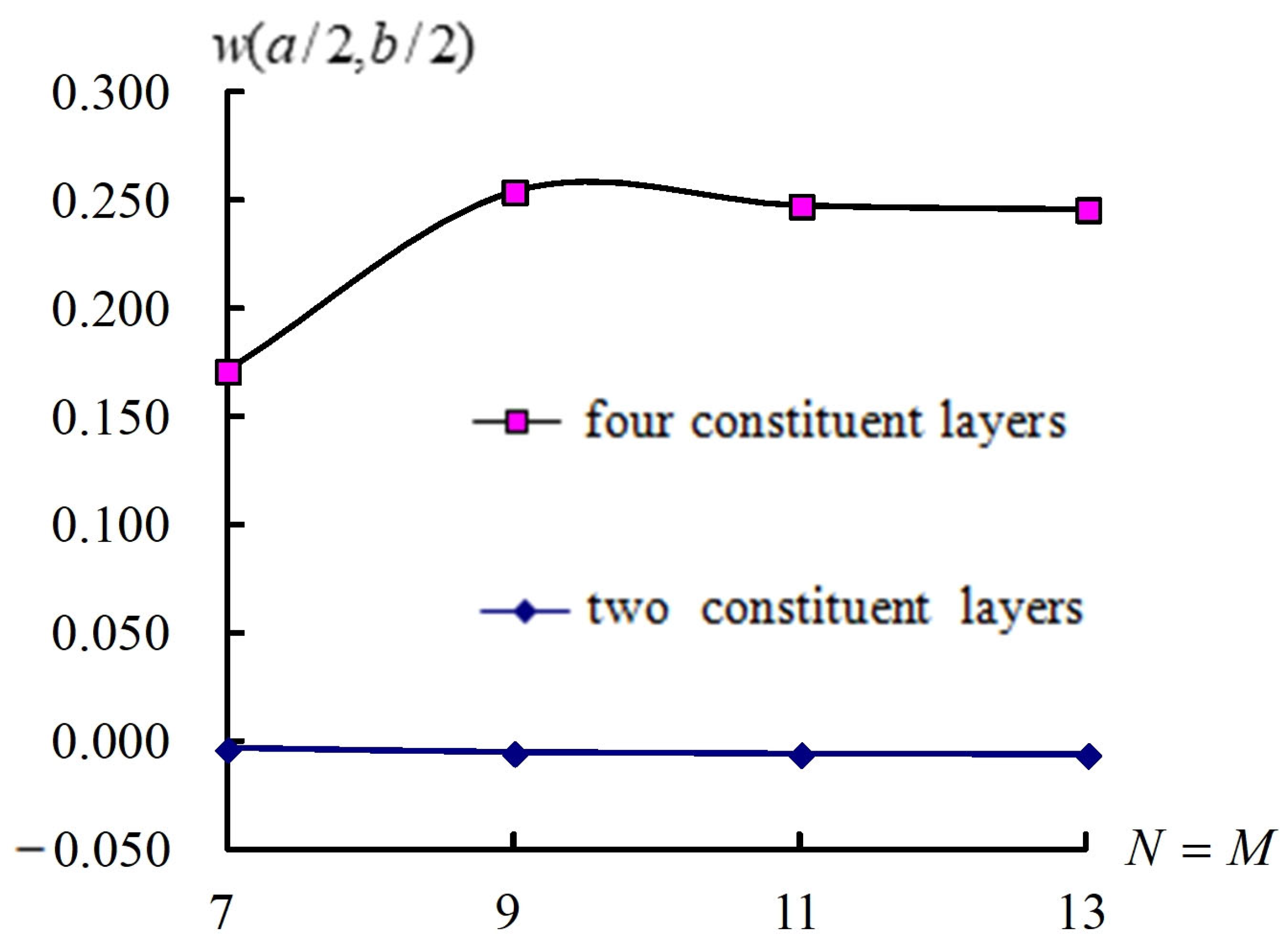
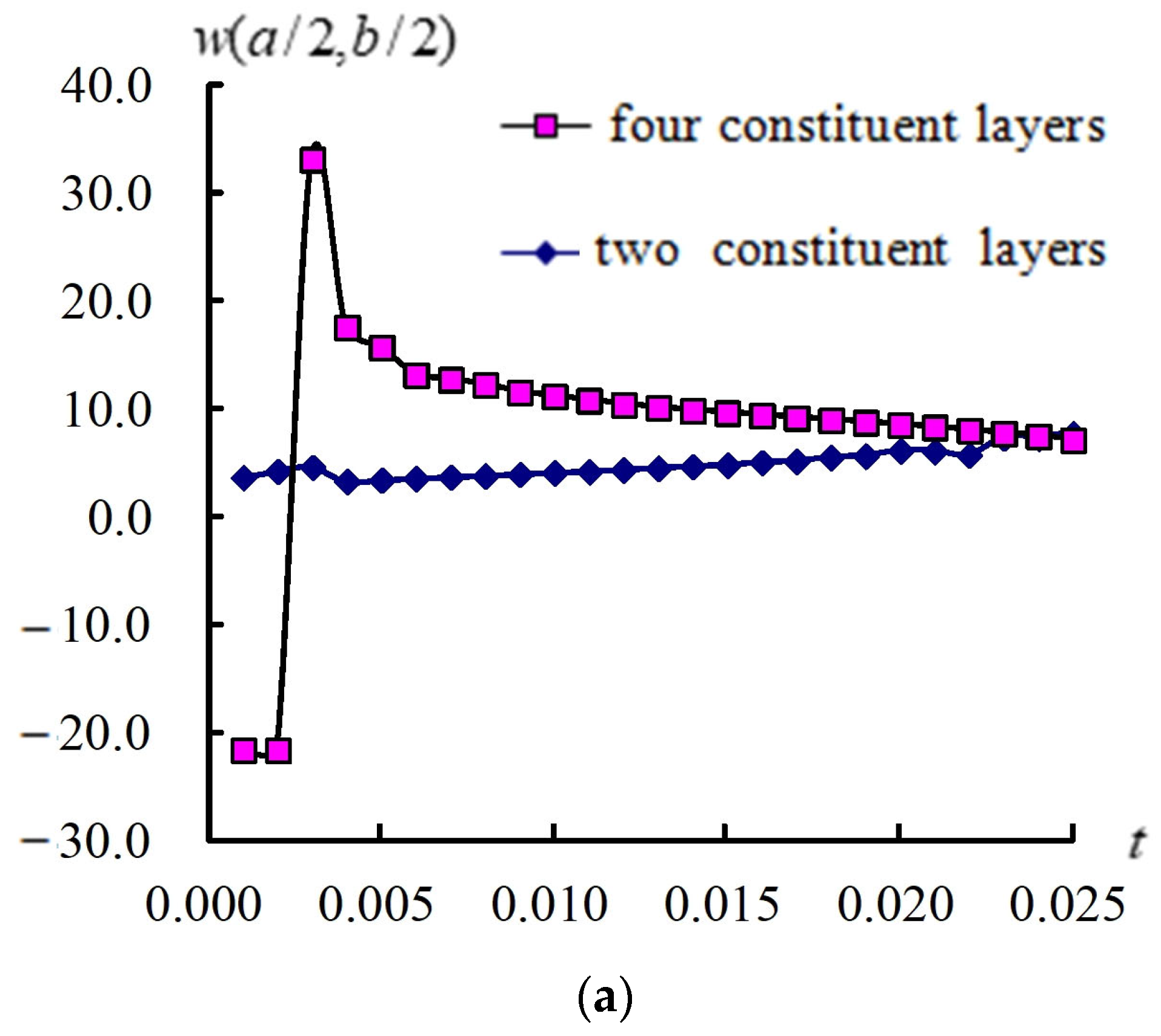
The w (a/2, b/2) (mm) in the convergence state at t = 6 s for θ 1 = 30 ° ,   45 ° , and 60 ° , respectively, in the vibration of c 1 = 0.925925/mm2 and non-dimensional k α with external heat flux for four layers, L/ h * = 5, T = 100 K and T ¯ 1 = 100 K are presented in Table 1. The error is 7.184 × 10⁻³ obtained for the w (a/2, b/2) under θ 1 = 30 ° and R n = 2. Also, the compared w (a/2, b/2) vs. N = M on θ 1 = 30 ° , R n = 2 case for four layers and two layers are presented in Figure 2. The steady amplitude of w (a/2, b/2) for four layers is larger than that for two layers. The discrepancies in two cases of two layers and four layers came from the effect of stiffness terms, e.g., Q ¯ i s j s , Q ¯ i * j * , A 11 , …,   F 11 and H 11 , …, H 44 . The converged grid number N × M = 13 × 13 was used in the following simulations. The values of non-dimensional k α obtained and used for four layers and two layers are presented in Table 2. Non-dimensional k α values are found in varied differences between four layers and two layers, respectively.

3.2. Responses for w (a/2, b/2) and Stress σ x

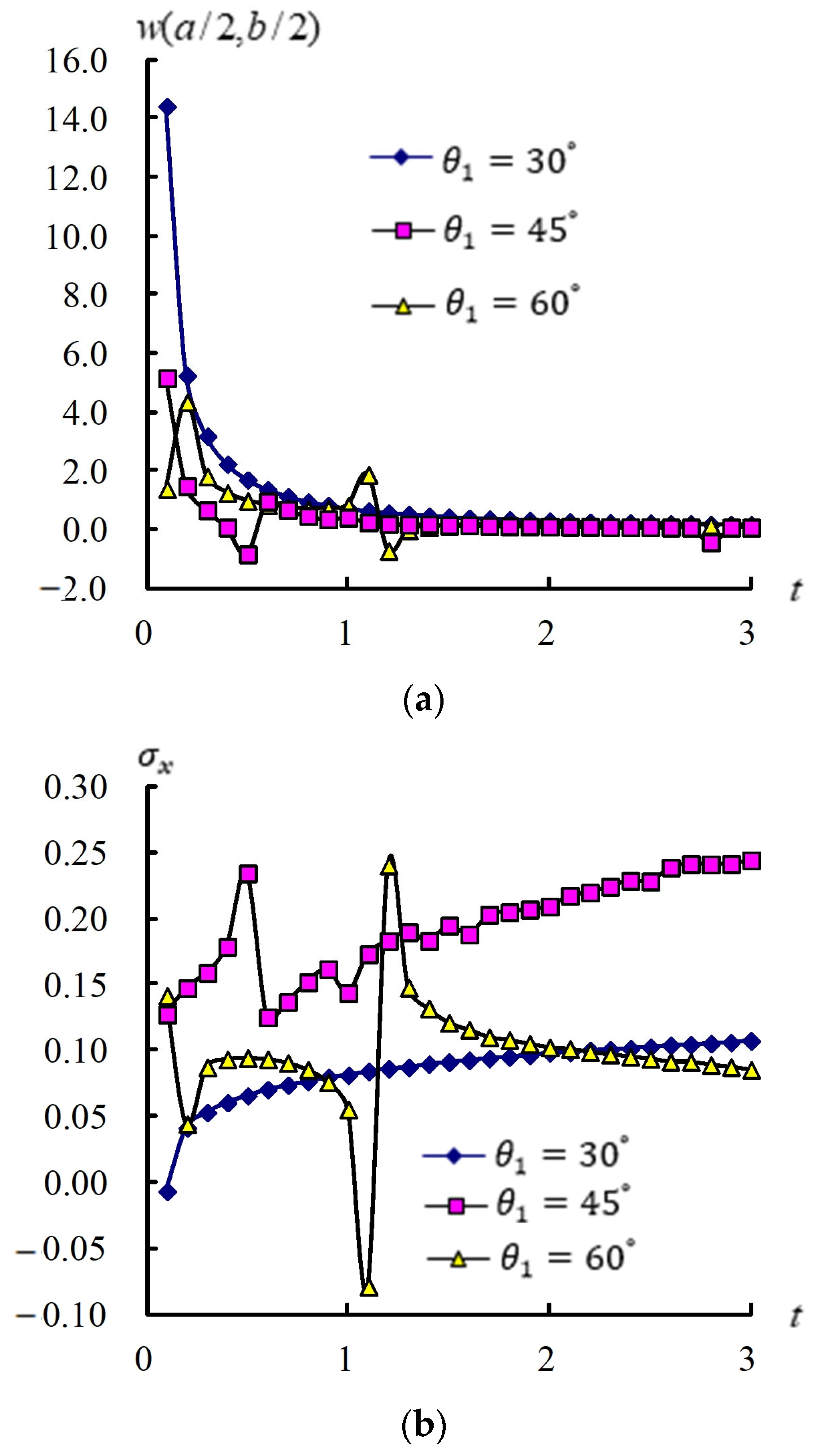
Figure 3 shows time responses for w (a/2, b/2) and σ x (GPa) in the coupled plates and circular shells with four layers, L/ h * = 5, c 1 = 0.925925/mm2, R n = 1, T = 600 K, T ¯ 1 = 100 K, and t = 0.1 s–3.0 s. The response values of w (a/2, b/2) versus t under θ 1 = 30 ° ,   45 ° and 60 ° , respectively, are shown. The maximum value of w (a/2, b/2) is 14.420517 mm found at t = 0.1 s under θ 1 = 30 ° . The w (a/2, b/2) values have converging tendencies that converged to 0.163256 mm under θ 1 = 30 ° , converged to 0.064898 mm under θ 1 = 45 ° , and converged to 0.140482 mm under θ 1 = 60 ° . The time responses of σ x on the center of inner surface are shown. The maximum value of σ x is 2.441 × 10⁻¹ GPa, which occurs at t = 3.0 s under the θ 1 = 45 ° case. The values of σ x demonstrate small oscillation during the period t = 0.5–0.6 s, then converge to 2.4418 × 10⁻¹ GPa for θ 1 = 45 ° , slightly increasing to 1.0726 × 10⁻¹ GPa for θ 1 = 30 ° and demonstrating small oscillation during the period t = 1.1–1.2 s, then decreasing to 8.5184 × 10⁻² GPa for the θ 1 = 60 ° case. There are small peaks in the responses of w (a/2, b/2) and σ x for the angle θ 1 = 60 ° due to a greater width effect of plates.

3.3. Responses of w (a/2, b/2) and σ x Versus T

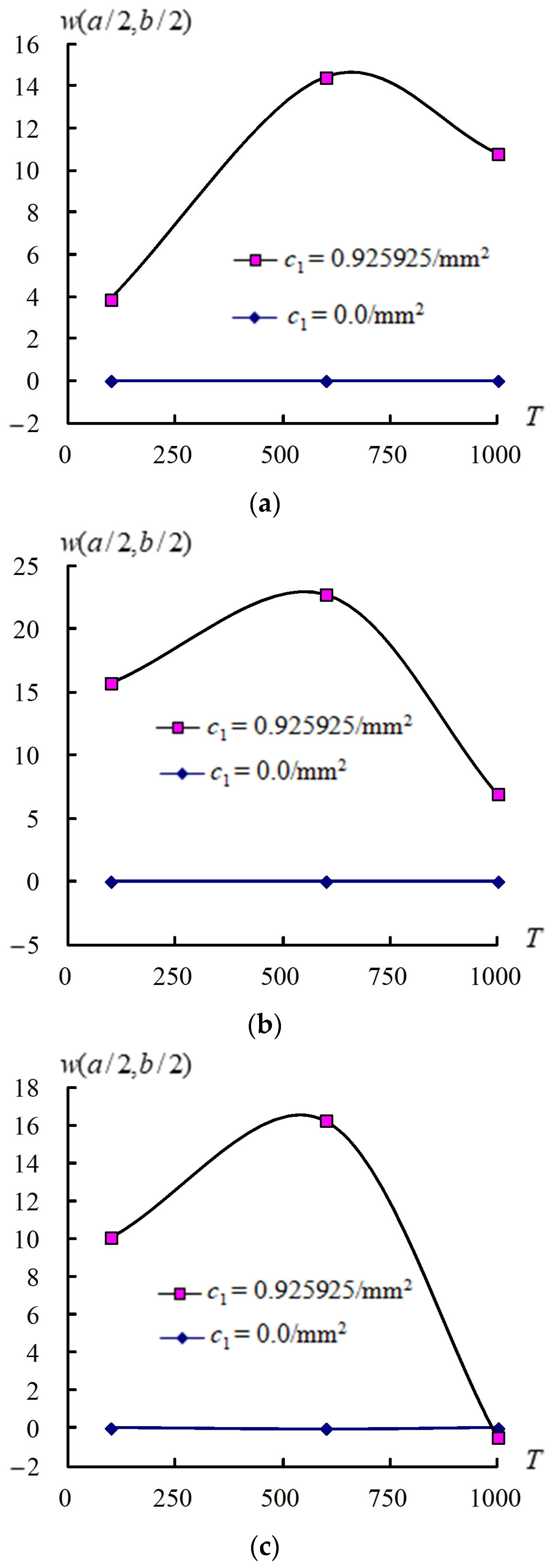
Figure 4 displays response values for w (a/2, b/2) vs. T under 100 K, 600 K, and 1000 K with R n for 1, 2, and 3 at t = 0.1 s for c 1 = 0.925925/mm2 and for c 1 = 0/mm2, respectively, in coupled plates and circular shells with four layers, L/ h * = 5, T ¯ 1 = 100 K under θ 1 = 30 ° . Responses of w (a/2, b/2) compared to T under c 1 = 0.925925/mm2 and R n = 1 case are shown, and the maximum of w (a/2, b/2) is 14.420517 mm found under T = 600 K. Values in w (a/2, b/2) increased from 100 K to 600 K then decreased from 600 K to 1000 K. The w (a/2, b/2) amplitude in R n = 1 under θ 1 = 30 ° can withstand higher T = 1000 K. Responses of w (a/2, b/2) compared to T for c 1 = 0.925925/mm2 and R n = 2 case are shown, and the maximum of w (a/2, b/2) is 22.746904 mm found under T = 600 K. Values in w (a/2, b/2) increased from 100 K to 600 K, then decreased from 600 K to 1000 K. The w (a/2, b/2) amplitude in R n = 2 under θ 1 = 30 ° can withstand higher T = 1000 K. Responses of w (a/2, b/2) verse T for c 1 = 0.925925/mm2 and R n = 3 case are shown, and the maximum of w (a/2, b/2) is 16.266580 mm found under 600 K. Values in w (a/2, b/2) increased from 100 K to 600 K, then decreased from 600 K to 1000 K. The w (a/2, b/2) amplitude in R n = 3 under c 1 = 0.925925/mm2 and θ 1 = 30 ° success for higher T = 1000 K. All w (a/2, b/2) amplitudes under c 1 = 0/mm2 are in constant small values.
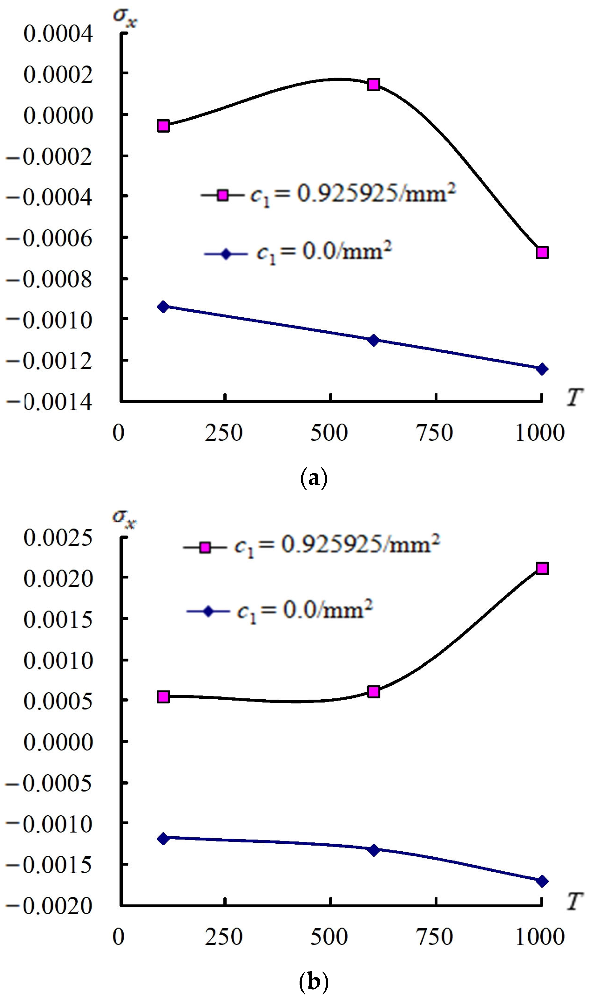
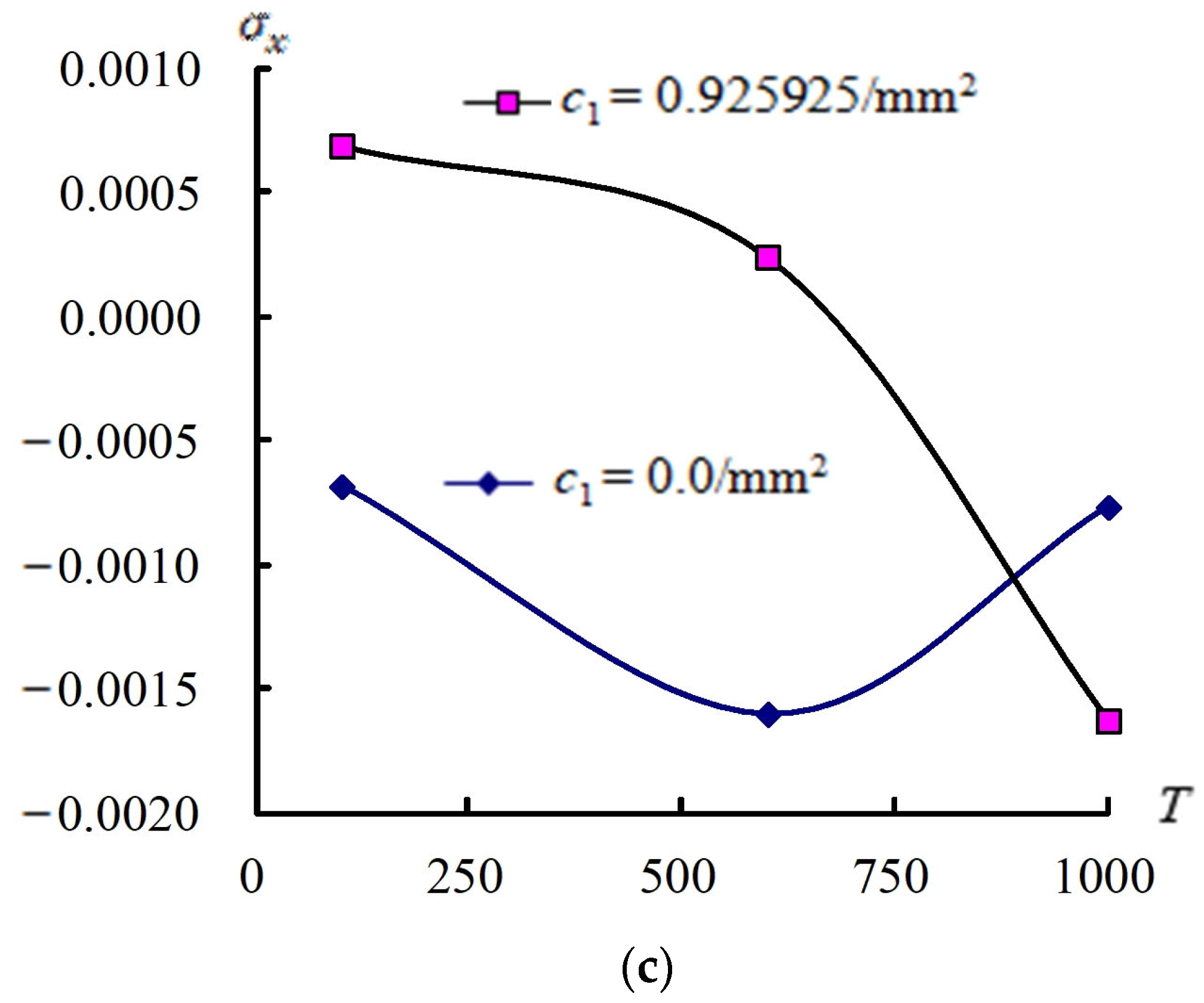
Figure 5 shows the σ x values on the center of the outer surface vs. T for R n (1, 2 and 3) at t = 0.1 s for c 1 = 0.925925/mm2 and for c 1 = 0/mm2, respectively, in coupled plates and circular shells with four layers, L/ h * = 5, T ¯ 1 = 100 K under θ 1 = 30 ° case. The curves of σ x vs. T under R n = 1 case are shown, the absolute maximum value of σ x is 1.2357 × 10⁻³ GPa occurs at T = 1000 K under c 1 = 0/mm2. Values in σ x increased from 100 K to 1000 K for c 1 = 0.925925/mm2 and c 1 = 0/mm2. The stress σ x of R n = 1 under θ 1 = 30 ° cannot succeed on T = 1000 K. The curves of σ x vs. T under R n = 2 case are shown, and the absolute maximum value of σ x is 2.1249 × 10⁻³ GPa, which occurs at T = 1000 K under c 1 = 0.925925/mm2. Values in σ x increased from 100 K to 1000 K for c 1 = 0.925925/mm2 and c 1 = 0/mm2, respectively. The σ x values of R n = 2 under θ 1 = 30 ° cannot succeed on T = 1000 K. The curves of σ x vs. T under R n = 3 case are shown, and the absolute maximum value of σ x is −1.6276 × 10⁻³ GPa, which occurs at T = 1000 K under c 1 = 0.925925/mm2. Values in σ x decreased from 100 K to 600 K and increased from 600 K to 1000 K under c 1 = 0.925925/mm2. The σ x values of R n = 3 under c 1 = 0.925925/mm2 and θ 1 = 30 ° cannot succeed on T = 1000 K. Values in σ x increased from 100 K to 600 K and decreased from 600 K to 1000 K under c 1 = 0/mm2. The σ x values of R n = 3 under c 1 = 0/mm2 and θ 1 = 30 ° can succeed on T = 1000 K.

3.4. Transient Responses of w (a/2, b/2) and σ x

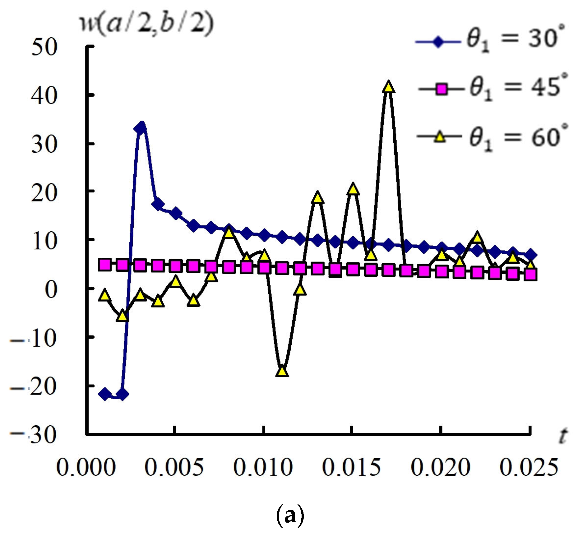
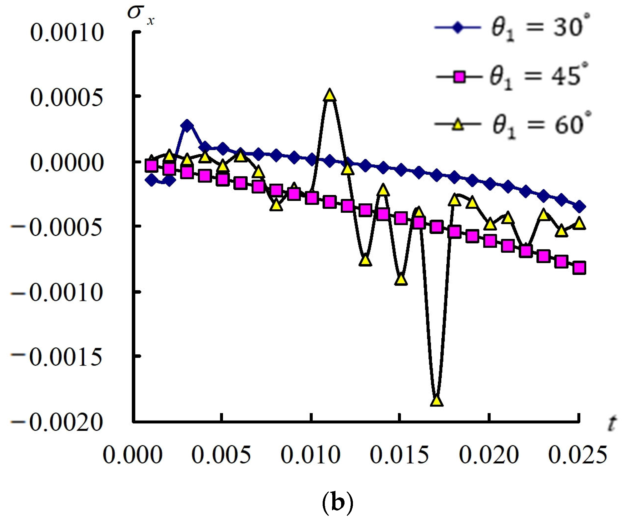
Transient data in w (a/2, b/2) and σ x responses on the center of outer surface for t = 0.001 s–0.025 s are presented in Figure 6 for coupled plates and circular shells with four layers, L/ h * = 5 under θ 1 = 30 ° ,   45 ° , and 60 ° , respectively, c 1 = 0.925925/mm2, natural frequency ω 11 = 0.008380/s,   γ = 15.707963/s, non-dimensional k α = −0.353743, T = 600 K, T ¯ 1 = 100 K, and R n = 1. The comparisons of transient response w (a/2, b/2) under θ 1 = 30 ° ,   45 ° , and 60 ° are shown. Transient responses of w (a/2, b/2) presented greater oscillation and decrease for θ 1 = 60 ° case. The comparisons of transient response σ x under cases in θ 1 = 30 ° ,   45 ° , and 60 ° are shown. Transient responses of σ x first oscillated then decreased under the θ 1 = 60 ° case.
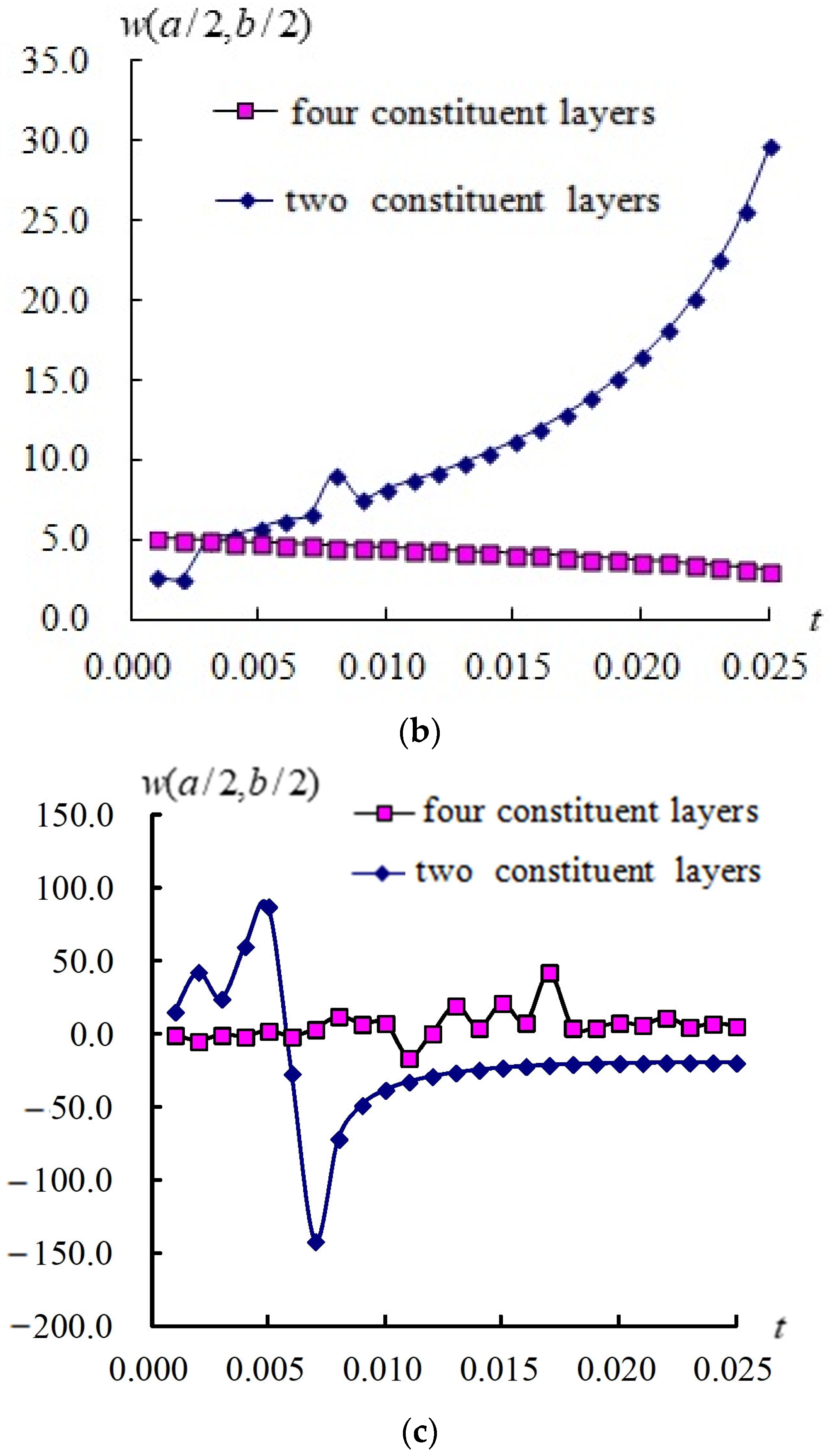
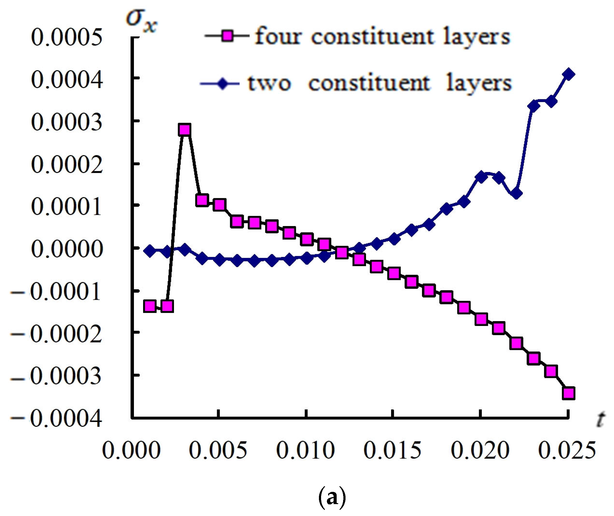
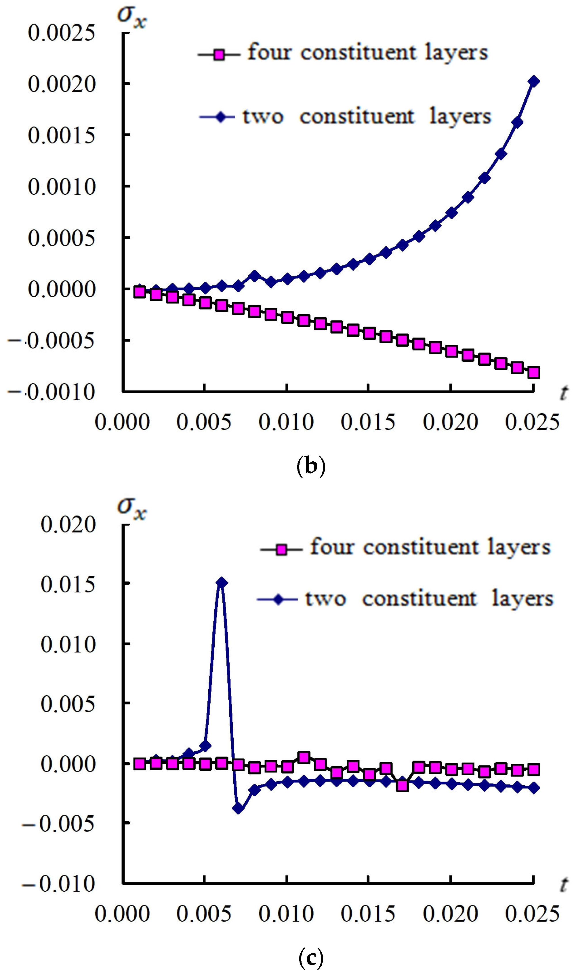
The compared w (a/2, b/2) responses in transient data under θ 1 = 30 ° ,   45 ° , and 60 ° , respectively, for two and four layers are shown in Figure 7. Transient w (a/2, b/2) data for four layers are greater than that for two layers under the θ 1 = 30 ° case. The compared transient responses of σ x under cases in θ 1 = 30 ° ,   45 ° , and 60 ° , respectively, for two and four layers are shown in Figure 8. The transient values of σ x for four layers are smaller than that for two layers under θ 1 = 60 ° case.

4. Conclusions

The GDQ results of w (a/2, b/2) and σ x are presented in the advanced vibration of FGM-coupled plates and circular shells with four same-thickness layers by mainly considering the non-dimensional shear correction and c 1 term of TSDT. The values of w (a/2, b/2) in R n = 1, 2, and 3 under c 1 = 0.925925/mm2 and θ 1 = 30 ° at t = 0.1 s can succeed on T = 1000 K. All amplitudes w (a/2, b/2) under c 1 = 0/mm2 are in constant small values. The σ x of R n = 3 under c 1 = 0/mm2 and θ 1 = 30 ° at t = 0.1 s can withstand higher T = 1000 K. The different values of non-dimensional k α are found in four layers and in two layers, respectively. The expressions for the non-dimensional k α and stiffness integrals in four layers are in more complicated forms than that in two layers. The steady amplitude of w (a/2, b/2) for four layers is larger than that for two layers. Also, transient data of w (a/2, b/2) for four layers are larger than that for two layers under the θ 1 = 30 ° case. Experimental details regarding hardware equipment, device, researchers, and time needed for experimental verification should be presented in future works if possible. Future research directions or possible applications should focus on the fields of relative structure and supersonic flow research. Moreover, additional applications of the research could be in engines in missiles and aircraft.

Funding

No external funder assisted in the research.

Data Availability Statement

All the data are generated by the author, and all data will be made available upon request.

Acknowledgments

The author expresses his thanks to the individuals who lended their help and support and the valuable suggestions from the reviewers.

Conflicts of Interest

The author declares no conflicts of interest.

Appendix A

The non-dimensional k α is expressed for four same-thickness layers of FGMs with the c 1 term as follows:
k α = 1 h * F G M Z S V F G M Z I V
where F G M Z S V = ( F G M Z S c 1 F G M Z S N ) 2 is entirely in the function of h * 6, F G M Z I V = F G M Z I 2 c 1 F G M Z I V 1 + c 1 2 F G M Z I V 2 is entirely in the function of h * 5, in which
F G M Z S = h * 2 h * 2 E f g m z 2 d z
F G M Z S N = h * 2 h * 2 E f g m z 4 d z
F G M Z I V = h * 2 h * 2   ( F G M Z c 1 F G M Z N ) 2 d z
and
F G M Z = E 2 E 1 h * / 2 R n [   ( z + h * 4 R n + 2 h * 4 R n + 2 ) /   ( R n + 2 ) h * 4   ( z + h * 4 R n + 1 h * 4 R n + 1 ) /   ( R n + 1 ) ] + E 1 2 z 2 h * 2 4 + E 4 E 3 h * / 2 R n [ z + h * 4 R n + 2 h * 4 R n + 2 R n + 2 ) h * 4   ( z + h * 4 R n + 1 h * 4 R n + 1 ) /   ( R n + 1 ) ] + E 3 2 z 2
F G M Z N = E 2 E 1 h * / 2 R n [   ( z + h * 4 R n + 4 h * 4 R n + 4 ) /   ( R n + 4 ) 3 h * 4   ( z + h * 4 R n + 3 h * 4 R n + 3 ) /   ( R n + 3 ) + 3 h * 4 2   ( z + h * 4 R n + 2 h * 4 R n + 2 ) /   ( R n + 2 ) h * 4 3   ( z + h * 4 R n + 1 h * 4 R n + 1 ) /   ( R n + 1 ) ] + E 1 4 z 4 ( h * 2 ) 4 + E 4 E 3 h * / 2 R n [ z + h * 4 R n + 4 h * 4 R n + 4 R n + 4 ) 3 h * 4   ( z + h * 4 R n + 3 h * 4 R n + 3 ) /   ( R n + 3 ) + 3 h * 4 2   ( z + h * 4 R n + 2 h * 4 R n + 2 ) /   ( R n + 2 ) h * 4 3   ( z + h * 4 R n + 1 h * 4 R n + 1 ) /   ( R n + 1 ) ] + E 3 4 z 4
FGMZI = FGMZI1 + FGMZI2 +…+ FGMZI10
FGMZIV1 = FGMZIV11 + FGMZIV12 +…+ FGMZIV119
FGMZIV2 = FGMZIV21 + FGMZIV22 +…+ FGMZIV210
in which FGMZI1, FGMZI2, …, FGMZI10; FGMZIV11, FGMZIV12, …, FGMZIV119; FGMZIV21, FGMZIV22, …, FGMZIV210 can be expressed in the functions of E 1 , E 2 , E 3 , E 4 , h * , and R n .

Appendix B

The stiffness integral parameters A 12 , B 12 , D 12 , E 12 , F 12 , H 12 , A 55 , B 55 , D 55 , E 55 , F 55 , and H 55 of four same-thickness layers in the FGM cylindrical shells are expressed as follows:
A 12 = A 21 = ν f g m 1 ν f g m 2 A E R M
B 12 = B 21 = ν f g m 1 ν f g m 2 B E R M
D 12 = D 21 = ν f g m 1 ν f g m 2 D E R M
E 12 = E 21 = ν f g m 1 ν f g m 2 E E R M
F 12 = F 21 = ν f g m 1 ν f g m 2 F E R M
H 12 = H 21 = ν f g m 1 ν f g m 2 H E R M 6
H 55 = H 66 = k α 2 1 + ν f g m H E R M 5
in which A E R M , B E R M , D E R M , E E R M , F E R M , H E R M 6 and H E R M 5 are in functions E 1 , E 2 ,   E 3 , E 4 , R , h * , and R n .

References

  1. Li, Z.; Jin, G.; Ye, T.; Yang, T.J.; Zhong, S.; Tian, L. A unified vibration modeling of open cylindrical shell-rectangular plate coupling structures based on the dynamic stiffness method. J. Sound Vib. 2023, 53, 117870. [Google Scholar] [CrossRef]
  2. Sun, Y.; Xiao, Y. Study on the influence of the internal elastic constraint stiffness on the vib-acoustic performance of a coupled plate-cylindrical shell system. Shock. Vib. 2023, 6668089, 1–11. [Google Scholar] [CrossRef]
  3. Chen, Z.; Wang, A.; Qin, B.; Wang, Q.; Zhong, R. Investigation on vibration of the functionally graded material–stepped cylindrical shell coupled with annular plate in thermal environment. J. Low Freq. Noise Vib. Act. Control. 2022, 41, 85–111. [Google Scholar] [CrossRef]
  4. Zhang, Y.; Shi, D.; He, D. Vibration characteristics of a laminated composite double-cylindrical shell system coupled with a variable number of annular plates. Materials 2022, 15, 4246. [Google Scholar] [CrossRef] [PubMed]
  5. Zhao, T.Y.; Yan, K.; Li, H.W.; Wang, X. Study on theoretical modeling and vibration performance of an assembled cylindrical shell-plate structure with whirl motion. Appl. Math. Model. 2022, 110, 618–632. [Google Scholar] [CrossRef]
  6. Zhao, Z.; Sheeng, M.; Yang, Y. Vibration transmission of a cylindrical shell with an interior rectangular plate with the receptance method. Adv. Acoust. Vib. 2012, 2012, 5817691. [Google Scholar] [CrossRef]
  7. Wang, Z.H.; Xing, J.T.; Price, W.G. A study of power flow in a coupled plate–cylindrical shell system. J. Sound Vib. 2004, 271, 863–882. [Google Scholar] [CrossRef]
  8. Messina, A.; Soldatos, K.P. Vibration of completely free composite plates and cylindrical shell panels by a higher-order theory. Int. J. Mech. Sci. 1999, 41, 891–918. [Google Scholar] [CrossRef]
  9. Hong, C.C. GDQ computation for thermal vibration of thick FGM plates by using third-order shear deformation theory. Mater. Sci. Eng. B 2023, 1294, 116208. [Google Scholar] [CrossRef]
  10. Hong, C.C. Advanced dynamic thermal vibration of thick FGM plates-cylindrical shells. Ocean. Eng. 2022, 266, 112701. [Google Scholar] [CrossRef]
  11. Babaee, A.; Jelovica, J. Nonlinear transient thermoelastic response of FGM plate under sudden cryogenic cooling. Ocean. Eng. 2021, 226, 108875. [Google Scholar] [CrossRef]
  12. Lee, S.J.; Reddy, J.N.; Rostam-Abadi, F. Transient analysis of laminated composite plates with embedded smart-material layers. Finite Elem. Anal. Des. 2004, 40, 463–483. [Google Scholar] [CrossRef]
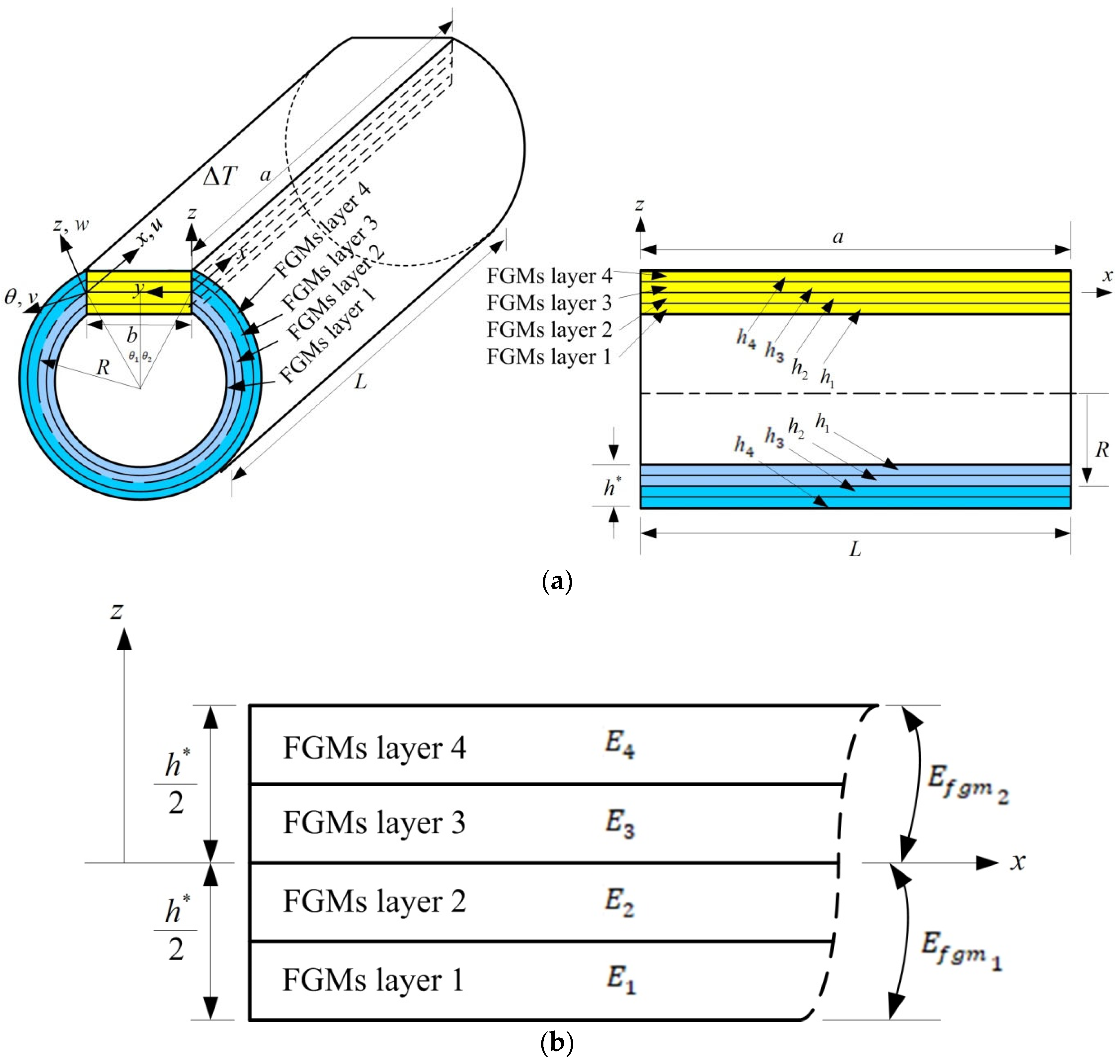
Figure 1. Four layers of FGM-coupled plate and circular shell for (a) thick FGM-coupled plates and circular shells with four layers and (b) Young’s modulus in four layers.
Fibers 13 00032 g001
Figure 2. Compared w (a/2, b/2) (mm) vs. N = M for two and four layers.
Fibers 13 00032 g002
Figure 3. w (a/2, b/2) and σ x vs. t for L/ h * = 5: (a) w (a/2, b/2) (mm) vs. t (s); (b) σ x (GPa) versus t (s).
Fibers 13 00032 g003
Figure 4. w (a/2, b/2) (mm) versus T (K) for (a) R n = 1; (b) R n = 2; (c)   R n = 3.
Fibers 13 00032 g004
Figure 5. σ x (GPa) versus T (K) for (a) R n = 1; (b) R n = 2; (c)   R n = 3.
Fibers 13 00032 g005aFibers 13 00032 g005b
Figure 6. Transient responses with γ = 15.707963/s for (a) w (a/2, b/2) (mm) vs. t (s); (b) σ x (GPa) vs. t (s).
Fibers 13 00032 g006aFibers 13 00032 g006b
Figure 7. Compared transient w (a/2, b/2) (mm) for two and four layers under (a)   θ 1 = 30 ° ; (b)   θ 1 = 45 ° ; (c)   θ 1 = 60 ° .
Fibers 13 00032 g007aFibers 13 00032 g007b
Figure 8. Compared transient σ x (GPa) for two and four layers under (a)   θ 1 = 30 ° ; (b)   θ 1 = 45 ° ; (c)   θ 1 = 60 ° .
Fibers 13 00032 g008aFibers 13 00032 g008b
Table 1. Convergence in FGM-coupled plate and circular shell for four layers.
L/ h * θ 1 GDQ Grids w (a/2, b/2) (mm) at t = 6 s
N × M R n = 1 R n = 2 R n = 3
5 30 ° 7 × 70.0290180.1707530.177768
9 × 90.0798250.253681−0.208156
11 × 110.0344910.247196−0.184317
13 × 130.0411320.245420−0.209937
45 ° 7 × 70.0115180.3136530.071740
9 × 90.0559200.3326970.050863
11 × 11−0.0013230.375168−0.093123
13 × 130.0496340.387151−0.148491
60 ° 7 × 70.0068890.081579−0.054453
9 × 90.0722840.3207330.186224
11 × 110.1621710.470269−0.065824
13 × 130.0575900.976272−0.079881
Table 2. Non-dimensional k α vs. c 1 , T, and R n for h * = 1.2 mm.
Number of Layers c 1 (1/mm2)T (K) k α
R n = 1 R n = 2 R n
40.925925100−0.343867−0.207462−0.123929
600−0.353743−0.222928−0.134674
1000−0.219714−0.137416−0.078338
2 100−0.619957−0.366153−0.214343
0600−0.646208−0.398133−0.233597
1000−0.370177−0.231584−0.132588
100−0.9227199.8526281.273259
0.925925600−3.5354021.5600710.855717
1000−0.252506−0.532898−1.614390
01001.2734991.3170371.278385
6001.200861.2320391.199164
10001.5165311.616821.563072
Disclaimer/Publisher’s Note: The statements, opinions and data contained in all publications are solely those of the individual author(s) and contributor(s) and not of MDPI and/or the editor(s). MDPI and/or the editor(s) disclaim responsibility for any injury to people or property resulting from any ideas, methods, instructions or products referred to in the content.