Highlights
What are the main findings?
- The FRESCO database provides a systematic 13-section structure that organizes experimental data on infilled RC frame systems with complete documentation of geometric, material, reinforcement, and loading parameters necessary for numerical modeling and validation.
- The automated 3D modeling framework converts database entries into detailed finite element models compatible with professional CAD software, with integrated capabilities for simulating composite strengthening interventions (FRP wrapping for columns/beams, TRM/FRP applications for infills).
What is the implication of the main finding?
- Validation through three comprehensive examples demonstrates close agreement between numerical models and experimental results, accurately capturing initial stiffness, peak loading, and post-peak behavior across different loading conditions (out-of-plane, in-plane, and spatial configurations).
- The open-source Python code with automated geometry generation significantly reduces time and effort for model preparation, enabling researchers to efficiently evaluate retrofitting strategies and develop sustainable strengthening solutions for existing RC frame structures with masonry infills worldwide.
Abstract
This paper presents FRESCO (Fiber REinforced Strengthening COmposite Database), a comprehensive open-source database designed to systematically organize experimental data on infilled RC frame systems that can be strengthened with advanced composite materials, such as Fiber-Reinforced Polymers (FRP), Textile-Reinforced Mortars (TRM), and other fiber-based solutions. The database employs open source practices while providing high-quality output that is fully compatible with leading commercial software packages such as ANSYS 2022R2. It uses Python3 as the main programming language and FreeCAD v1.0 as the model generation engine, with a systematic 13-section structure that ensures complete documentation of all parameters necessary for numerical modeling and validation of analytical methods. Two types of databases are provided: in comma-separated format (.csv) for common everyday interaction and in JSON format (.json) for easy programmatic access. The database features automated 3D modeling capabilities, converting experimental data into detailed finite element models with solid RC frame geometry, reinforcement details, and infill configurations. Validation through three comprehensive examples demonstrates that numerical models generated from the database closely match experimental results, with response curves that closely match the initial stiffness, the peak loading and the post-peak stiffness degradation phase across different loading conditions. The database focuses on RC frame systems with unreinforced brick infill. Reflecting the term FRESCO, which in Greek (φρέσκο) means “fresh”, the database is designed as a dynamic, evolving resource, with future versions planned to include RC walls and full buildings.
1. Introduction
Reinforced concrete (RC) frame structures with masonry infill panels represent one of the most common structural systems worldwide, particularly in seismically active regions (like Greece, Italy etc.) [1]. A large portion of these structural systems were designed with outdated seismic provision and until now most of them have not been properly identified and retrofitted, resulting in catastrophic consequences [2,3]. Under lateral loading, these composite systems exhibit complex behavior, with the overall structural response greatly influenced by the interaction between the relatively brittle masonry infill and the flexible RC frame [4]. The use of advanced composite materials, such as Fiber-Reinforced Polymers (FRP) [5], Textile-Reinforced Mortars (TRM or FRCM) [6], and other fiber-based solutions [7,8,9], to strengthen infilled RC frame systems has become a viable strategy for improving structural performance without sacrificing architectural functionality. However, the variety of material combinations and failure modes, along with the intricate interaction mechanisms between frames, infills, and strengthening systems, makes it difficult and time-consuming for researchers and practitioners to create reliable design methodologies.
Several experimental databases have been developed to systematically organize and analyze the real behavior of full-scale or scaled infilled RC frame systems. A comprehensive review of existing databases reveals both significant contributions and notable limitations that motivate the development of the FRESCO (Fiber REinforced Strengthening COmposite) database. The initial investigation began by using a well-known scholar search engine, Google Scholar, with the search term “infilled reinforced concrete frame database.” The results yielded significant databases that already contained a considerable number of specimens. One common observation was a significant overlap in the experimental studies, suggesting that even though some databases were constructed at different time periods, no significant differences in the documented specimens were observed. This indicates that the variety of existing experiments needs to be somehow extended with physically or numerically defined supplementary data. Nevertheless, some of the most significant databases are reported herein, along with their scope and content.
The database from [10] contains 264 experimental tests on mixed infill frame systems. Of these, 191 specimens featured reinforced concrete frames, while the remaining 73 used steel frames. Ninety-seven percent of the experiments consisted of single-story structures, and the common loading protocols employed were pseudo-dynamic, quasi-static, or monotonic. Only 3% of the database included multi-bay specimens (7 out of 264). The database encompasses a variety of masonry units and panels, with both reinforced and unreinforced configurations, including designs with and without openings, and with and without retrofitting measures. It is organized with a clear structure, documenting geometric characteristics of the frames and infill, reinforcement details for both frames and panels, material properties, and global response and damage categorization. The primary purpose of the database was to develop empirical equations for modeling infill panels as equivalent struts and to train machine learning models for failure mode classification.
The MID 1.0 database from [11] comprises a total of 16 experimental campaigns, culminating in 114 tests. Of these, 13 involved bare frame systems, while the remaining 101 included infills. They created a detailed Microsoft Excel spreadsheet for storing and manipulating the dataset. The database structure consists of six sections. Section one covers general information, such as test topologies (whether the frame is bare, the infill is full or includes doors or windows), the number of stories and bays (85% are one-story, with the remaining 15% being two-story, and over 90% being single-bay), loading conditions, and opening information. Section two is dedicated to the infills, providing detailed information about the block/brick properties, mortar characterization, and, in some cases, infill prisms. Nevertheless, this section contains many “n.a.” (not available) values, as in many studies this information is not provided properly. Section three discusses the frame properties, including cross section information and properties, beam specifications, and concrete and reinforcement mechanical properties. Section four addresses the longitudinal and transverse reinforcement of columns and beams. Section five categorizes the failure mode into five modes: A: Corner Crushing, B: Diagonal Cracking, C: Sub-panel Diagonal Cracking, D: Bed Joints Sliding, and E: Reinforced Concrete (RC) Frame Failure. Damage states DS2 (moderate damage) and DS3 (heavy damage) are defined according to EMS98 [12] standards. Finally, Section six contains multi-linear fits of monotonic envelope curves for all 114 tests. The primary use of the database is for Performance-Based Earthquake Engineering (PBEE) applications, risk assessment, and retrofitting and design optimization for seismic performance.
The expanded database MID 1.1 [13] is a successor to the previous version, MID 1.0. It contains a total of 134 tests from 24 references, compared to 16 in the version 1.0 campaign. Almost 93% of the specimens feature a single-bay, single-story configuration with solid infills. The scale of 72% of these specimens ranges from 1:2 to 1:3, with 20% representing full-scale (1:1). A significant addition to this version was the inclusion of additional infill unit types such as Autoclaved Aerated Concrete (AAC), calcarenite, vitrified ceramic, and fly ash bricks. The organizational structure remains the same as the original six-section format. In this version, an empirical model was developed to predict equivalent strut width using power-law regression.
Another notable database is from [14], which consists of 200 experimental tests from recent decades related to frames with hollow clay brick infills. These tests are valuable for developing probabilistic fragility relationships essential for seismic risk assessment and design. What makes this work unique is its focus on creating a homogeneous and extensive database specifically for hollow clay brick infills—a characteristic feature of Italian and Mediterranean reinforced concrete (RC) building stock, but one that has been underrepresented in previous research.
The current version of the database focuses on RC frame systems that have infill made of unreinforced brick material. The examined systems in many cases have response capacity degradation or undergo significant damage accumulation; therefore, a retrofitting strategy is needed. The strengthening of the systems with composite material can be applied to beams, columns, beam–column joints, frame–infill interfaces, or infills, either separately or in combination based on system deficiencies. Two database formats are provided: in comma-separated format (.csv) for common everyday interaction and in JSON format (.json) for easy programmatic access using Python. The script for editing and updating the database is openly provided to the community. Additionally, for easy advanced 3D modeling, a script for converting the database to a real-world simulation model (solid RC frame with reinforcement details and infill configuration) is provided so it can be used as a practical application baseline. Furthermore, a basic linear representation (frame configuration) of the models is provided for further performance-based analysis simulations. These features are not provided in any other databases to the knowledge of the authors, and are expected to further enhance productivity and research efficiency. Finally, a few examples of database use cases with advanced 3D simulation and proposed pipeline are provided. In the last steps of the pipeline process (detailed simulation process), basic understanding of the advanced 3D simulation process is assumed, as a detailed explanation is out of the scope of this study. For more details, the reader can refer to these publications [15,16,17,18].
2. FRESCO Database Architecture
The FRESCO database is developed using open source practices while providing high-quality output that is fully compatible with leading commercial software packages such as ANSYS. It uses Python 3 [19] as the main programming language and FreeCAD v1.0 [20] as the model generation engine. Then, models are validated using ANSYS Explicit Dynamic 22R2 [21]. Characteristic examples are provided Section 5. The database is divided into 13 main sections.
Section 1: Reference Group contains the basic identification information for each entry and consists of the following attributes:
- “specimen_scale”—The scale of the specimen defined in the manuscript (1, 0.5, 0.1, … etc);
- “source”—Site for reference source (webpage or doi);
- “title”—Title of the reference source;
- “authors”—List of authors for the reference source (comma-separated string);
- “year”—Publication year of the reference source.
Section 2: Frame Geometry Group captures the physical dimensions and geometric characteristics of the reinforced concrete frame structure. The geometric definitions and dimensional notations for these attributes are illustrated in Figure 1.
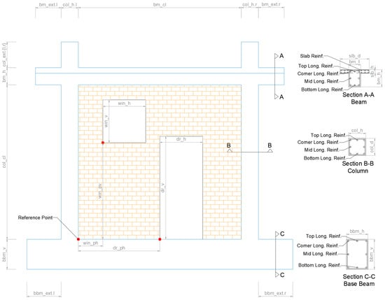
Figure 1.
FRESCO database notations for the geometry of the frame, infill, and cross section reinforcement.
- “frm_h”—Height of the frame calculated from the top surface of the base beam to the top surface of the top beam (floor-to-floor height);
- “frm_l”—Length of the frame calculated from the external surfaces of the columns;
- “col_h”—Column dimension parallel to frame plane;
- “col_d”—Column dimension perpendicular to frame plane;
- “bm_h”—Beam height (vertical dimension);
- “bm_t”—Beam thickness (horizontal dimension);
- “bbm_h”—Base beam height;
- “bbm_t”—Base beam thickness;
- “slb_d”—Slab depth (dimension perpendicular to frame plane);
- “slb_h”—Slab height (dimension parallel to frame plane);
- “col_ext”—Column extension above beam top surface;
- “bm_ext”—Beam extension outside the external surfaces of the columns;
- “bbm_ext”—Base beam extension outside the external surfaces of the columns.
Section 3: Infill Geometry Group documents the masonry infill panel characteristics, including opening configurations and construction details:
- “inf_type”—Infill configuration (one_wythe, two_wythe, or none);
- “inf_opn_type”—Opening type (window, door, mix, or none);
- “inf_win_h”—Window horizontal dimension (length);
- “inf_win_v”—Window vertical dimension (height);
- “inf_win_ph”—Window horizontal position from reference point;
- “inf_win_pv”—Window vertical position from reference point;
- “inf_door_h”—Door horizontal dimension;
- “inf_door_v”—Door vertical dimension;
- “inf_door_ph”—Door horizontal position from reference point;
- “inf_door_pv”—Door vertical position from reference point;
- “inf_dp”—Infill depth from the main reference point;
- “inf_bnd_pat”—Infill bond pattern (running or stack);
- “inf_inff_intfc”—Infill–frame interface condition (mortar_bond, seismic_joint, dowels, or gap);
- Interface dimensions for all four sides (bottom, left, top, right);
- Unit specifications including length, height, thickness, and joint thicknesses.
Section 4: Reinforcement Details Group provides comprehensive documentation of steel reinforcement throughout all structural elements. This section captures the complete reinforcement layout including longitudinal and transverse reinforcement configurations for columns, beams, base beams, and slabs. It documents critical regions with enhanced reinforcement, spacing patterns, bar sizes, and quantities, as well as concrete cover dimensions for all structural components.
Section 5: Concrete Properties Group documents the fundamental material characteristics of concrete, including compressive strength, elastic modulus, testing age, and density measurements that are essential for structural analysis and modeling.
Section 6: Steel Properties Group captures the mechanical properties of reinforcing steel, encompassing yield and ultimate strengths, elastic modulus, and material density required for accurate structural behavior prediction.
Section 7: Infill Mechanical Properties documents the comprehensive material characteristics of masonry components, including properties of both masonry units and mortar. This section covers density measurements, compressive strengths in multiple directions, mortar classification types, and assembly behavior under various loading conditions.
Section 8: Loading Group—In-Plane defines the complete loading protocols applied parallel to the frame plane, documenting whether loading is monotonic or cyclic, cycle characteristics, standard protocol references, and the magnitude of applied vertical loads on structural elements.
Section 9: Loading Group—Out-of-Plane defines loading protocols applied perpendicular to the frame plane, maintaining the same comprehensive structure as in-plane loading to capture all relevant loading parameters for three-dimensional structural behavior.
Section 10: Response Group—Global captures the overall structural response characteristics, including stiffness properties, peak load capacities, drift relationships, energy dissipation capabilities, and primary failure mode identification at the system level.
Section 11: Response Group—Local documents detailed local behavior and damage patterns, providing comprehensive descriptions of crack development, failure mechanisms, damage progression sequences, and strain distribution patterns throughout the testing process.
Section 12: Retrofit Techniques provides a concise description of any strengthening or retrofitting methods applied to the specimen, limited to four sentences maximum to maintain database consistency while capturing essential intervention details.
Section 13: General Comments offers flexible space for additional user notes, observations, or clarifications not captured in the structured sections, ensuring comprehensive documentation of unique specimen characteristics or testing conditions.
This systematic 13-section structure ensures proper documentation of all parameters necessary for numerical modeling (e.g., with OpenSees), validation of analytical methods, and development of sustainable retrofitting solutions for reinforced concrete frame structures with masonry infills (see Figure 2).
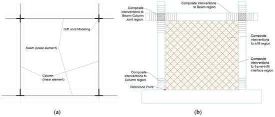
Figure 2.
FRESCO database models ready for (a) PBEE analysis and (b) composite intervention.
The database code is organized in a way that is general and modular. An object-oriented approach was followed. Three main classes compile the code:
- FrescoUnits—A sophisticated unit conversion system that handles all relevant physical quantities required for this campaign such as length, force, pressure, time, strain, density, work, and temperature;
- FrescoReinforcementParser—A specialized parser designed to handle reinforcement notation strings with embedded dimensions, converting between various units while preserving the semantic structure of reinforcement specifications;
- FrescoDatabase—The main database management class that orchestrates data handling, unit conversion, validation, and persistence operations.
The “FrescoDatabase” class incorporates an internal, predefined unit system (using the “FrescoUnits” class), allowing the user to import entries in any desired unit system. There are two ways the user can enter data: as a simple numerical value or string, or as a list containing a value and a unit system. For example, to enter the frame height “frm_h,” the user can use “frm_h”: 2400 or “frm_h”: [2400, “mm”]. In both cases, the system recognizes the length as 2400 mm, which is the default for the code. The user could also use “frm_h”: [2.4, “m”], in which case, internally, the code will convert it to mm. When first using a database entry, it is highly recommended to utilize the TEMPLATE_RCF dictionary located in the Template folder within the Example folder. This helps avoid unnecessary errors and ensures all necessary fields are available. Once the template is completed, the user can import the dictionary into the database using the add_entry method. If there is an error in the content, or if the user wishes to update an entry, they can use overwrite = True in the add_entry method to override the entire entry, or they can use the update_entry method to update only specific fields. To delete an entry, the user should use the remove_entry method, providing the entry ID. During each operation—addition, update, or deletion—the code automatically saves the database state. If this is not desired, the user can disable this feature using auto_save = False. The “FrescoDatabase” class features an automatic backup system with timestamps, which is enabled by default. It backs up immediately when an existing dataset is opened to prevent data loss during editing sessions. The user is free to disable this during class initialization. The database can export the entire database to a new one in JSON format using the export_json function or in CSV format using the export_csv function. A detailed explanation and common mistakes to avoid are documented in the UserGuide.md. Contributions to the database are welcome, as outlined in the Contribution.md. Complete documentation, database files, and Python scripts are provided in Supplementary Materials.
3. Database Content and Scope
The FRESCO database is the result of an extensive literature review of existing databases related to reinforced concrete frames with unreinforced masonry infills, and their individual components: beams, columns, slabs, and infill panels. The primary objective is to identify properly controlled test specimens that can serve as benchmarks for developing sustainable retrofitting interventions—specifically, composite rope confinement, Fiber-Reinforced Polymer (FRP) systems, Textile-Reinforced Mortar (TRM) applications, and other sustainable intervention methods—for green infrastructure systems. The general content and scope are depicted in Figure 3. The section pertaining to RC Frame Elements RC infilled Structure and RC infilled Frame for Out-of-Plane will be added iteratively, either in subsequent releases or during dynamic updates, reflecting the term FRESCO, which, in Greek (φρέσκο), means “fresh”. This indicates that the database is not static but rather a dynamic, evolving resource.
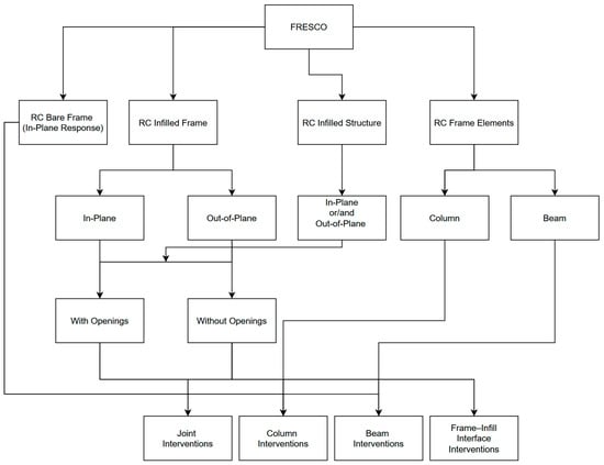
Figure 3.
FRESCO database content and scope.
The main content of the up-to-date entries of the database is depicted in Table 1.

Table 1.
FRESCO database content for version 1.0.
The complete notations for the database are provided in Table A2 (Appendix A). The full database in CSV and JSON formats is available in Supplementary Materials.
4. Automated 3D Modeling Framework
Following the open source philosophy of the current database project, the Python3 code for automatic geometry generation is also released and provided in Supplementary Materials. The file responsible for model generation is defined in “model_creator.py”. For geometry creation, the FreeCAD v1.0 [20] Python API is utilized, as defined in the Help section of the program. For reading the database entry and extracting the relevant information needed for creating the model, the “FrescoRCFrameDatabase” class from “database_editor.py” is used. Some utility functions are created to standardize the generation process and significant effort was made to use this logic as much as possible. The detailed explanation is not provided in the manuscript for two reasons. Firstly, it is much clearer to understand the functions in the code with the detailed comments that are provided. Secondly, there may be some small changes in the definitions and processes as the database evolves and it is easy to follow these with the history tracking capabilities that the repository contains. Nevertheless, for completeness, a detailed flow chart generated using Mermaid language (included in the repository) is depicted in Figure 4 and discussed in the following paragraphs. The process involves the following main steps:
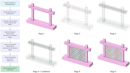
Figure 4.
Process of automatic 3D generation of the model: flow chart and different stages of the model creation.
- Initialization of the Database and FreeCAD Document;
- Extraction of the relevant data for the defined database entry;
- Creation of the solid 3D RC bare frame geometry;
- Creation of the Transverse Reinforcement (Stirrups) for all members;
- Creation of the Longitudinal Reinforcement for all members;
- Creation of the Infill Assembly Brick pattern (optionally with openings).
During the initialization phase, a new FreeCAD document is created along with an instance of the database. The relevant geometric information from the database is then parsed. A light error check is utilized to ensure values are properly defined. Nevertheless, it is the user’s responsibility to ensure that data imported during the entry phase, using the “add_entry” functionality of the database, are reasonable and correspond to physical quantities.
In the next step, the geometry of the complete bare frame is generated, including both columns and beams. These are the minimal elements required to successfully generate the frame. Despite this, in experimental setups, the base beam is mandatory for the frame to be fully fixed so it can be properly tested in a laboratory. For numerical analyses, however, this condition is often simulated with a simple fixed constraint. This fixed constraint restricts displacement in all global directions to zero. In this context, it should be noted that, for 3D mesh elements, the rotational fix constraint is not applied as it would be for linear elements. However, if a close simulation of the base joint flexibility is an important parameter in the study, a proper definition of this component is mandatory. To properly anchor the longitudinal reinforcement within the beam–column joint, appropriate extensions to both columns and beams is necessary. The script provides this important functionality through the “ext_” attributes (which refer to extensions) for beams, columns, and the base beam. Finally, there is an option to include a slab in the top region of the beam to form a T-shaped cross section. This slab extends throughout the total length of the beam, which is computed from the frame’s length and the sum of the two external beam extensions. After defining each part, the individual components of the model are fused together to define a unified geometry that is easily meshable with high-quality hexahedral (HEX) elements (with external FEM software (e.g. ANSYS Explicit Dynamics 2022R2) or code). These can be meshed using either first-order 8-node or second-order 20-node elements; however, for large deformations, we propose using first-order 8-node elements and reduced integration to achieve better convergence. The default orientation for proper definition of the cross section and reinforcement is depicted in Figure 5.
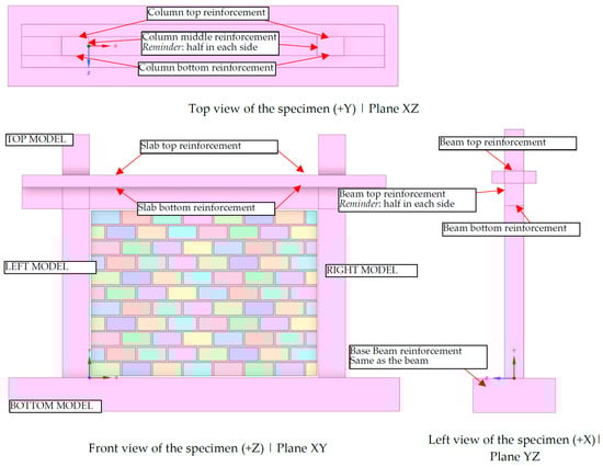
Figure 5.
Default orientation of the cross section for columns, beam, and base_beam for the automated model creation and reinforcement reference indication in line with the global axis orientation.
The following phase involves reinforcement creation within the model. For numerical simulation, the reinforcement is generated based on the methodology described in [15]. Consequently, both longitudinal and transverse bars share common nodes and are defined based on their centerline axis. This process ensures equivalent reinforcement placement alongside the cross section, accounting for rebar thickness. For both columns and beams, there are generation options for critical regions of transverse reinforcement and non-critical regions (the middle region). The script is configured to generate reinforcement from the bottom critical region; additionally, for columns, it accounts for the extension part where the reinforcement will be equal to the bottom reinforcement. Therefore, if no critical region is applied, the model is reinforced uniformly across its entire length; only the critical bottom option is provided with the conception that all regions are critical. The same logic is applied to beams and the base beam, with the only difference being that top and bottom are replaced with left and right. The orientation of bottom, top, left, and right is depicted in Figure 5 for clarity with BOTTOM MODEL, TOP MODEL, LEFT MODEL and RIGHT MODEL, respectively.
The model creation concludes with the generation of the infill and potential openings for windows and doors. The code contains two distinct configurations for the infill bond: one for running bond and one for stacked bond. Each generation begins by assuming that the first row on the left side of the model is constructed using full brick size, then populating until the end of the available opening. There are two alternatives for the end condition: an exact fit of the bricks or cutting the length of the last brick to match the remaining gap. For the stacked bond, the row is populated vertically, using the same assumptions as with the last brick in the first row. For the running bond, the first brick of the second row starts with half a brick size. The next (second) brick of the second row is then placed and populated using the same logic as the first brick in the first row. Finally, these first two rows act as a pattern, populating vertically to fill the frame’s vertical clear height. In both cases, for the infill bond, the thicknesses of the head and bed joints were properly considered. After generating the bricks, a mortar solid element equal to the size of a full panel is generated, and the FreeCAD v1.0 cut option is used to remove the equivalent brick region for the mortar, leaving only the head and bed joints exposed. Then, this same operation is conducted separately for both the mortar and brick parts to create the openings. Lastly, the interface regions are filled with solid elements equivalent to the interface thickness and infill thickness.
The geometry is exported using the “.step” file type, which adheres to the ISO standard (specifically ISO 10303-21 [55]) and is compatible with protocol 214. This format can export both solid and line elements. The resulting files are readable by modern professional CAD systems such as ANSYS SpaceClaim v2022R2 [21], a significant achievement of our database models.
In many cases, the final geometry, after visual comparison with the source figures, may require additional manual edits before it is ready for proper 3D finite element analysis. Additional operations can be performed either manually using the script that is included in the repository or manually within the graphic user interface of FreeCAD or a similar CAD system. Either way, the provided code is organized in a way that allows users to refer to any past object created during the automated generation process and perform freely all types of transformations, including but not limited to translation, rotation, scaling, Boolean operations (cut, fuse), etc.
5. Database Use Examples
This section details three unique examples demonstrating how to properly use the database. For each example, we begin with a simple explanation of input data and then entry usage, followed by a brief description of the finite element model creation. At the end of each example, we compare the results obtained from the models to their experimental counterparts. The first use case examines a RC frame filled with an unreinforced infill panel that is subjected to an out-of-plane monotonic load. The second use case investigates a double wythe panel under in-plane loading, and the third explores extrapolating the in-plane database to create a 3D RC frame model of a four-column, four-beam slab with a cantilever and strong base.
5.1. Example 1: Out-of-Plane Loading of Specimen
The current example is drawn from the study by Koutas and Bournas [56]. The researchers examined different configurations of reinforced concrete frames filled with unreinforced infill and Textile-Reinforced Mortar (TRM) that were subjected to out-of-plane loading. This example examines the model with ID S_CON, in which the infill consists of a single wythe and was eccentrically placed with no strengthening. For all tested specimens, the RC frame configuration was the same. The frame had a total height of 1500 mm, measured from the top surface of the base beam to the top surface of the slab (floor to floor height), and a length of 2100 mm, measured from the external surfaces of the columns. The beam’s cross section was T-shaped, with a slab thickness of 90 mm, a height of 250 mm, and a web thickness of 140 mm. The reinforcement was B500C steel with a diameter of 10 mm, placed at the four corners of the beam. Mild steel with a diameter of 6 mm and a spacing of 150 mm was used for the transverse reinforcement. The concrete cover for the beam portion was 20 mm. The slab portion had a cover of 10 mm and was reinforced with a grid of mild steel with a diameter of 8 mm, spaced at 150 mm intervals. The columns had rectangular cross sections with a width of 200 mm and a depth of 140 mm. The concrete cover for the column cross section was 10 mm. The columns were reinforced longitudinally at the corners with four rebars of diameter 10 mm, using B500C steel. Stirrups with a diameter of 6 mm were used at a spacing of 150 mm. All transverse reinforcement was uniformly placed, with no distinction made between critical and non-critical regions. The base had dimensions of 250 mm in height and 2500 mm in length overall and an approximate depth of 540 mm. The original reinforcement was not provided, so heavy reinforcement was assumed. The brick dimensions were 215 × 102.5 × 65 -mm (length × height × thickness) with mortar thickness of 10 mm for head and bed joint. The geometry, as generated by the database code and manually edited afterward, is depicted in Figure 6a and Figure 6b, respectively.
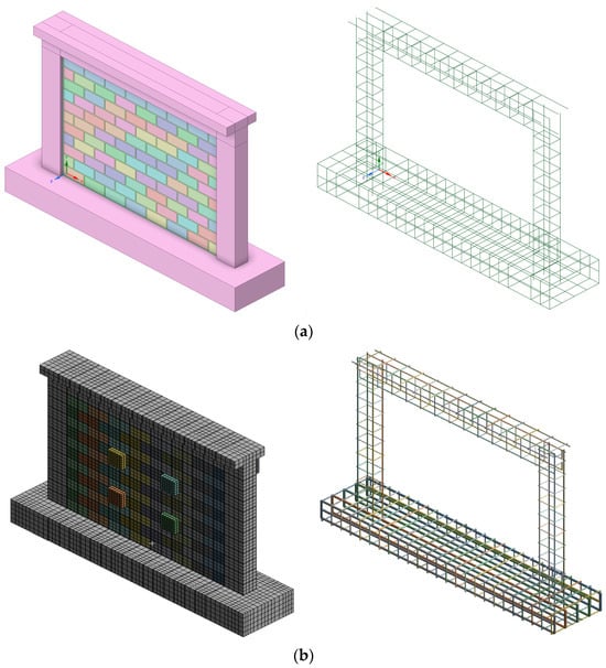
Figure 6.
S_CON model generated by (a) database code and (b) manual edited inside FEM analysis.
Access to the database is conducted using the TEMPLATE_RCF dictionary, located in the “Examples -> ManuscriptsExamples -> Templates” folder. The full reference file is located in the “ManuscriptsExamples” folder as “example1.py”. Table A2 depicts the key pair for this specimen’s entry. Initially, we create an instance of “FrescoDatabase” as “db” and then enter data using the method “db.entry (entry_id = 1, entry_data = entry_koutas_and_bournas_2019)”. Finally, in “create_rcf_model.py,” we select the appropriate database name and ID and run the script. After the script runs, we obtain the model “model_id_1.step” in the “Models” folder.
For this example, Method V2 was used for the modeling of reinforcement, taking reinforcement interactions into proper account as described in [15]. During the manual editing process, the scale of the stirrups around the longitudinal reinforcement was adjusted to avoid common nodes for stirrups and longitudinal rebars, as the interaction will be properly considered by the internal finite element program algorithm. Furthermore, an adjustment was made for the start of the first stirrup from the top surface of the base, in addition to the introduction of one stirrup in the beam–column joint region. Moreover, the proper order of slab reinforcement was adjusted based on sketches from the original study. Finally, loading and support elements were added to be equivalent to the experimental setup.
The final results of the analytical and experimental data, in terms of the P-d curve and final damage state, using ANSYS 22R2, are depicted in Figure 7. The out-of-plane load was applied perpendicular to the wall through four loading pads arranged in a rectangular pattern in the center region of the wall, with displacement measured at the center.
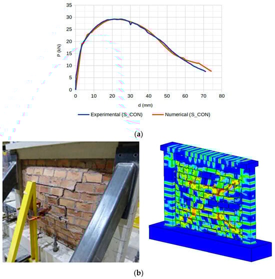
Figure 7.
S_CON result for explicit dynamic analysis: (a) the P-d curve with out-of-plane loading applied through four pads in a rectangular configuration at the wall center (displacement measured at center) and (b) the failure mechanism (experimental image is adapted from [56]).
The response curve closely matched the initial stiffness, the peak loading, and the post-peak stiffness degradation phase. In general, we can conclude that it followed the non-linear behavior of the experimental specimen. The failure pattern was similar to the experimental one, matching the typical arching mechanism.
5.2. Example 2: In-Plane Loading Specimen
The experimental test, numerically solved in the present example using 3D finite element method, are the SIF-I-A and SIF(DTRM)-I-B from the work of Akhoundi et al. [53]. The specimen (SIF-I-A) represents an unstrengthened infilled frame configuration and the specimen (SIF(DTRM)-I-B) represents the same frame configuration strengthened with the textile reinforced mortar (TRM) technique using textile meshes developed at the University of Minho. The original construction from which the characteristic frame was selected for solution is representative of typical construction in Portugal during the 1960s. The laboratory study of the frame was performed on a smaller scale, with a reduction ratio of 0.52. All parameters were adjusted accordingly using Cauchy’s similarity rule. The geometry and arrangement of the reinforcement are shown in Figure 8a, while the characteristic sections for the columns and beams, and the types of bricks, are shown in Figure 8b. The concrete was of class C20/25, and the reinforcement was of class A400R, possessing a characteristic tensile yield strength of 400 MPa. The binding mortar was of class M5 and had a thickness of 10 mm. The strength of the bricks was determined experimentally, yielding a maximum compressive strength parallel to the length of the bricks of 2.53 MPa (COV 22.8%) and 8.17 MPa (COV 3.4%) for the external and internal leaves, respectively. Throughout the experiment, a constant vertical compressive load of 160 kN was applied to the top of the columns.
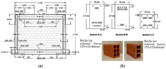
Figure 8.
SIF-I-A model (a) geometry with reinforcement and (b) cross sections and brick information (adapted from [53]).
The basic entry values of imported data in the database are depicted in Table A3. The reinforcement configuration also followed Method.V2 from [15]. For the second wythe, a copy of the existing infill was performed, with the thickness adjusted. During manual editing, holes in the bricks were added, as depicted in the original infill units (see Figure 8b). The specimen was fixed at the bottom and proper vertical load were applied to the top of the column. The geometry, as generated by the database code and manually edited afterward, is depicted in Figure 9a and Figure 9b, respectively. The numerical specimen was tested using a push-over load approach. In addition to the infill specimen SIF-I-A and SIF(DTRM)-I-B, the bare frame specimen was also tested.
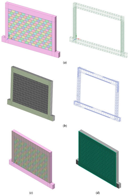
Figure 9.
SIF-I-A model generated by (a) database code and (b) manual edited inside FEM analysis, and SIF(DTRM)-I-B model generated by (c) database code and (d) manual edited inside FEM analysis.
The comparison of P-d curves, as shown in Figure 10a, again reveals a close match between the numerical and experimental results. The numerical results slightly overestimate the initial stiffness and slightly underestimate the plateau phase. For the bare frame, the opposite conditions were observed. For the strengthened specimen SIF(DTRM)-I-B, the numerical model captures the enhanced stiffness and strength, showing good agreement with experimental results in the initial loading phase and post-peak behavior. The observed discrepancies in the initial stiffness may be attributed to idealized boundary conditions in the numerical model or variations in material properties not fully captured in the simulation. The slight underestimation of the plateau phase could result from simplified plasticity models or mesh sensitivity in the post-yield region. This level of agreement provides confidence in using the numerical model for parametric studies and design optimization.
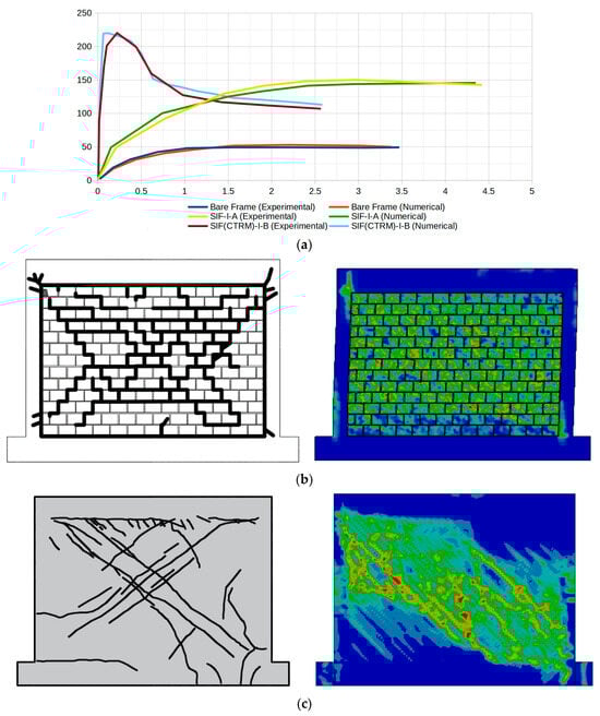
Figure 10.
SIF-I-A, SIF(DTRM)-I-B and bare frame result for explicit dynamic analysis. (a) The P-d curves and crack pattern for (b) SIF-I-A and (c) SIF(DTRM)-I-B (experimental images is adapted from [53]).
The experimental crack pattern in Figure 10a shows predominantly diagonal cracking through the masonry units and mortar joints, forming a stepped crack pattern typical of masonry shear failure. The numerical model utilizing the ANSYS 22R2 environment (Figure 10b) successfully captures this general diagonal failure mechanism, with high strain/damage concentrations following similar trajectories. There is also evidence of damage accumulating on the upper and lower portions of the columns. The numerical model for SIF(DTRM)-I-B (Figure 10c) successfully captures the general failure mechanism, with damage patterns following similar trajectories, as observed experimentally.
5.3. Example 3: Spatial Specimen Generation
The final example is a single-story test specimen from the GREENERGY project [57], designed to simulate pre-Eurocode Greek construction practices. With a plan configuration of 2.70 m by 2.70 m and an overall height of 1.95 m, the specimen was engineered to permit a realistic assessment of seismic vulnerabilities and subsequent retrofitting strategies for vertical forest integration [58,59], through numerous shake table tests at Democritus University of Thrace (DUTh, Reinforced Concrete and Seismic Design lab). The structural system comprised four square columns (130 mm × 130 mm) supported by strong foundation beams anchored securely to the seismic table and interconnected at the upper level by hidden beams and a substantial protruding slab. The slab’s extension was intended to facilitate future integration of vertical forest anchoring systems. The average concrete strength throughout the specimen can be characterized as C20/25 grade. Longitudinal reinforcements for the columns consisted of four 8 mm rebars at the corners and stirrups with diameter of 5.5 mm at 60 mm intervals (see Figure 11). The infills were constructed in accordance with established Mediterranean construction practices. The overall construction methodology aimed to accurately replicate typical building materials and construction practices prevalent in older structures to facilitate a realistic evaluation of seismic response and inform future retrofit designs.
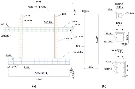
Figure 11.
GREENERGY-1 specimen model: (a) geometry with reinforcement and (b) cross sections and brick information.
The geometry, as initially generated by the database code and then manually edited, is depicted in Figure 12a and Figure 12b, respectively. The initial geometry from the database generation was properly rotated around the center of the spatial structure, and overlapping elements occurred. The entries from Table A4 were used. The overlapping parts were fused together, and the final spatial model was generated. Square portions from the beam–column were cut for both linear and solid elements to eliminate the additional parts, so the final model could be created. The model from Figure 12b was fixed in the bottom surfaces and loaded with push-over approach to determinate the ultimate capacity for 1% drift ratio related to Serviceability Limit State (SLS).
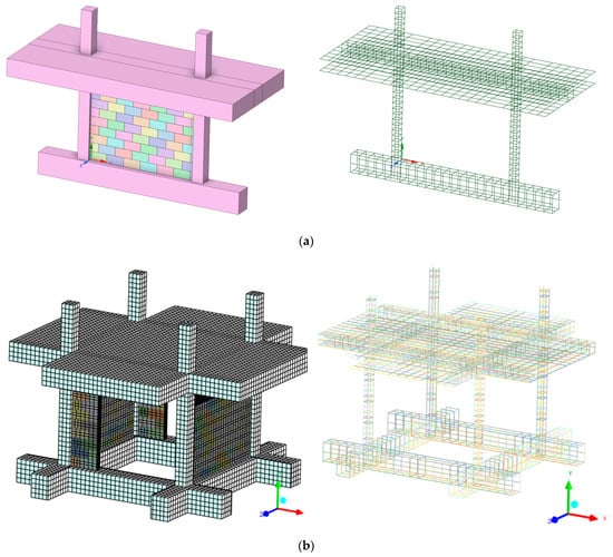
Figure 12.
GREENERGY-1 model generated by (a) database code and (b) manually edited inside FEM analysis.
The experimental specimen was tested as-built without any strengthening interventions on a seismic table using 12 successive excitation cycles of the 1978 Thessaloniki earthquake and white noise, alternatively. The maximum peak acceleration of 1.1 g for the induced earthquake excitation marked the termination of this experimental phase (as-built, phase A). During the last excitation, the specimen deformed up to a 1% drift ratio and withstood an equivalent total horizontal force of approximately 50 kN, which exactly matched the results from the numerical analysis. In terms of damage accumulation, the results from Figure 13a,b are compared from two different points of view. In the side view (Figure 13a), the experimental damage pattern shows concentrated cracking primarily in the lower portion of the structure and frame–infill interfaces, indicated by the red lines. The corresponding numerical analysis on the right displays stress concentrations (shown in green and yellow colors) that closely align with these experimentally observed damage locations. The stress distribution indicates high strain concentrations at the base–wall interface and in specific joint regions.
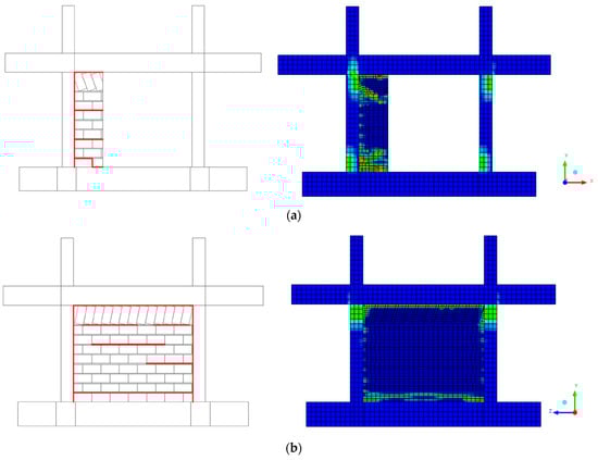
Figure 13.
GREENERGY-1 result for explicit dynamic analysis of the failure mechanism for EQ 1.1 g: (a) side view and (b) front view.
The front view (Figure 13b) provides complementary information about the damage progression. Here, the experimental sketch shows a more distributed cracking pattern across the wall surface, with horizontal crack formations indicated by the red lines. The numerical model captures this behavior well, showing stress concentrations that correlate spatially with the experimental crack patterns. The color gradient from blue (low stress) to green/yellow (high stress) clearly delineates the zones of damage initiation and propagation. It is important to mention that both schemes indicate critical debonding in the frame–infill interfaces.
6. Conclusions
The FRESCO (Fiber REinforced Strengthening COmposite Database) database represents a comprehensive solution to the limitations observed in existing databases for reinforced concrete frames with masonry infills. As noted in the Introduction, “the variety of material combinations and failure modes, along with the intricate interaction mechanisms between frames, infills, and strengthening systems, makes it difficult and time-consuming for researchers and practitioners to create trustworthy design methodologies.” The FRESCO database directly addresses this challenge through its systematic 13-section structure that ensures complete documentation of all parameters necessary for numerical modeling, validation of analytical methods, and development of sustainable retrofitting solutions for reinforced concrete frame structures with masonry infills.
The database’s unique contributions extend beyond traditional data compilation. Following the open source logic, the automated 3D modeling framework provides Python3 code for automatic geometry generation that creates models readable by modern professional CAD systems such as ANSYS SpaceClaim. The validation examples demonstrate that the response curve closely matched the initial stiffness, the peak loading, and the post-peak stiffness degradation phase when comparing numerical models to experimental results, confirming the database’s reliability for practical applications.
Future versions may expand the database scope to include steel frames, RC walls, and full buildings, broadening its applicability for seismic assessment and retrofitting applications. The open source nature, combined with comprehensive documentation and practical modeling tools, positions FRESCO as a valuable resource for advancing research in composite strengthening of infilled frame systems and supporting the development of sustainable retrofitting interventions for existing building stock worldwide.
Supplementary Materials
All supporting materials can be downloaded from https://github.com/Vachan-Vanian/FRESCO-database. Materials include: FRESCO database (CSV and JSON formats), Python scripts for database editing and 3D model generation, documentation, and usage examples.
Author Contributions
Conceptualization, V.V. and T.R.; methodology, V.V. and T.R.; software, V.V.; validation, V.V. and T.R.; formal analysis, V.V. and T.R.; investigation, V.V. and T.R.; resources, V.V. and T.R.; data curation, V.V.; writing—original draft preparation, V.V.; writing—review and editing, V.V. and T.R.; visualization, V.V.; supervision, T.R.; project administration, T.R.; funding acquisition, T.R. All authors have read and agreed to the published version of the manuscript.
Funding
The research project is implemented in the framework of H.F.R.I call “Basic research Financing (Horizontal support of all Sciences)” under the National Recovery and Resilience Plan “Greece 2.0” funded by the European Union—NextGenerationEU (H.F.R.I. Project Number: 015376).
Data Availability Statement
The complete FRESCO database, including all data entries, processing scripts, and documentation, is publicly available in the GitHub repository at https://github.com/Vachan-Vanian/FRESCO-database (accessed on 6 November 2025). The repository contains (1) experimental database in both CSV and JSON formats, (2) open source Python scripts for database manipulation and model generation, (3) examples, and (4) comprehensive documentation for database structure and usage. All data and code are released under MIT license to encourage research collaboration and practical applications. Users are encouraged to cite this work when utilizing the database and to contribute additional experimental data through the repository’s contribution guidelines.
Conflicts of Interest
The authors declare no conflicts of interest.
Appendix A
Table A1 serves as a complete, standalone reference that users can consult without searching through the narrative sections.
Note: When material properties are not reported in the database or source manuscript, users should derive missing values using appropriate design standards or literature sources for similar materials.
Table A1.
Complete notations for the FRESCO database.
Table A1.
Complete notations for the FRESCO database.
| Entry | Unit Type | Explanation |
|---|---|---|
| Section 1: Reference Group | ||
| specimen_id | None | The name of the specimen defined in the manuscript |
| specimen_scale | None | The scale of the specimen defined in the manuscript (1, 0.5, 0.1, etc.) |
| source | None | Site for reference source (webpage or doi) |
| title | None | Title of the reference source |
| authors | None | List of authors for the reference source (comma-separated string) |
| year | None | Publication year of the reference source |
| Section 2: Frame Geometry Group | ||
| frm_h | Length | Height of the frame calculated from the top surface of the base_beam to the top surface of the top_beam. (also known as floor to floor height) |
| frm_l | Length | Length of the frame calculated from the external surfaces of the columns |
| col_h | Length | Column dimension parallel to frame plane |
| col_d | Length | Column dimension perpendicular to frame plane |
| bm_h | Length | Beam height |
| bm_t | Length | Beam thickness |
| bbm_h | Length | Base_Beam height |
| bbm_t | Length | Base_Beam thickness |
| slb_d | Length | Slab depth (dimension perpendicular to frame plane) |
| slb_h | Length | Slab height (dimension parallel to frame plane) |
| col_ext | Length | Column extension above beam top surface |
| bm_ext | Length | Beam extension outside the external surfaces of the columns |
| bbm_ext | Length | Base beam extension outside the external surfaces of the columns |
| Section 3: Infill Geometry Group | ||
| inf_type | None | 1. one_wythe 2. two_wythe 3. none |
| inf_opn_type | None | 1. window 2. door 3. mix 4. none |
| inf_win_h | Length | Window horizontal dimension (length) |
| inf_win_v | Length | Window vertical dimension (height) |
| inf_win_ph | Length | Window horizontal position from main reference point |
| inf_win_pv | Length | Window vertical position from main reference point |
| inf_door_h | Length | Door horizontal dimension (length) |
| inf_door_v | Length | Door vertical dimension (height) |
| inf_door_ph | Length | Door horizontal position from main reference point |
| inf_door_pv | Length | Door vertical position from main reference point |
| inf_dp | Length | Infill depth from the main reference point |
| inf_bnd_pat | None | Infill bond pattern 1. running 2. stack |
| inf_inff_intfc | None | Infill infill–frame interface condition info 1. mortar_bond 2. seismic_joint 3. dowels 4. gap |
| inf_interface_bottom | Length | Infill interface fill/gap dimension at bottom |
| inf_interface_left | Length | Infill interface fill/gap dimension at left |
| inf_interface_top | Length | Infill interface fill/gap dimension at top |
| inf_interface_right | Length | Infill interface fill/gap dimension at right |
| inf_ul | Length | Infill unit length (horizontal) |
| inf_uh | Length | Infill unit height (vertical) |
| inf_ut | Length | Infill unit thickness (depth) |
| inf_uhead_t | Length | Infill head joint thickness (vertical) |
| inf_ubed_t | Length | Infill bed joint thickness (horizontal) |
| Section 4: Reinforcement Details Group | ||
| col_cover | Length | Cover till the external surface of the transverse reinforcement |
| col_long_reinf_corner | Length | Column longitudinal reinforcement at corners (e.g., ‘4#20’)— dimensions auto-convert |
| col_long_reinf_top | Length | Column longitudinal reinforcement at top (e.g., ‘2#16’)— dimensions auto-convert |
| col_long_reinf_mid | Length | Column longitudinal reinforcement at mid-height (e.g., ‘2#16’)—dimensions auto-convert |
| col_long_reinf_bot | Length | Column longitudinal reinforcement at bottom (e.g., ‘2#16’)— dimensions auto-convert |
| col_trans_crit_top_distance | Length | Column transverse reinforcement critical top region distance |
| col_trans_crit_top_reinf | Length | Column transverse reinforcement at critical top region (e.g., ‘2#8@150’)—dimensions auto-convert |
| col_trans_crit_bot_distance | Length | Column transverse reinforcement critical bottom region distance |
| col_trans_crit_bot_reinf | Length | Column transverse reinforcement at critical bottom region (e.g., ‘2#8@150’)—dimensions auto-convert |
| col_trans_mid_reinf | Length | Column transverse reinforcement at mid-height (e.g., ‘1#8@250’)—dimensions auto-convert |
| bm_cover | Length | Cover till the external surface of the transverse reinforcement |
| bm_long_reinf_corner | Length | Beam longitudinal reinforcement at corners (e.g., ‘2#20’)— dimensions auto-convert |
| bm_long_reinf_top | Length | Beam longitudinal reinforcement at top (e.g., ‘3#16’)— dimensions auto-convert |
| bm_long_reinf_mid | Length | Beam longitudinal reinforcement at mid-span (e.g., ‘2#16’)— dimensions auto-convert |
| bm_long_reinf_bot | Length | Beam longitudinal reinforcement at bottom (e.g., ‘3#20’)—dimensions auto-convert |
| bm_trans_crit_left_distance | Length | Beam transverse reinforcement critical left region distance |
| bm_trans_crit_left_reinf | Length | Beam transverse reinforcement at critical right region (e.g., ‘2#8@100’)—dimensions auto-convert |
| bm_trans_crit_right_distance | Length | Beam transverse reinforcement critical right region distance |
| bm_trans_crit_right_reinf | Length | Beam transverse reinforcement at critical right region (e.g., ‘2#8@100’)—dimensions auto-convert |
| bm_trans_mid_reinf | Length | Beam transverse reinforcement at mid-span (e.g., ‘1#8@200’)—dimensions auto-convert |
| bbm_cover | Length | Cover till the external surface of the transverse reinforcement |
| bbm_long_reinf_corner | Length | Base_Beam longitudinal reinforcement at corners (e.g., ‘2#20’)—dimensions auto-convert |
| bbm_long_reinf_top | Length | Base_Beam longitudinal reinforcement at top (e.g., ‘3#16’)— dimensions auto-convert |
| bbm_long_reinf_mid | Length | Base_Beam longitudinal reinforcement at mid-span (e.g., ‘2#16’)—dimensions auto-convert |
| bbm_long_reinf_bot | Length | Base_Beam longitudinal reinforcement at bottom (e.g., ‘3#20’)—dimensions auto-convert |
| bbm_trans_crit_left_distance | Length | Base_Beam transverse reinforcement critical left region distance |
| bbm_trans_crit_left_reinf | Length | Base_Beam transverse reinforcement at critical left region (e.g., ‘2#8@100’)—dimensions auto-convert |
| bbm_trans_crit_right_distance | Length | Base_Beam transverse reinforcement critical right region distance |
| bbm_trans_crit_right_reinf | Length | Base_Beam transverse reinforcement at critical right region (e.g., ‘2#8@100’)—dimensions auto-convert |
| bbm_trans_mid_reinf | Length | Base_Beam transverse reinforcement at mid-span (e.g., ‘1#8@200’)—dimensions auto-convert |
| slb_cover | Length | Slab cover |
| slb_top_l_reinf | Length | Slab Top reinforcement parallel to frame plane (e.g., ‘#12@200’)—dimensions auto-convert |
| slb_top_d_reinf | Length | Slab Top reinforcement perpendicular to frame plane (e.g., ‘#12@250’)—dimensions auto-convert |
| slb_bot_l_reinf | Length | Slab Bottom reinforcement parallel to frame plane (e.g., ‘#12@200’)—dimensions auto-convert |
| slb_bot_d_reinf | Length | Slab Bottom reinforcement perpendicular to frame plane (e.g., ‘#12@250’)—dimensions auto-convert |
| Section 5: Concrete Properties Group | ||
| conc_density | Density | Concrete density |
| fc | Pressure | Concrete compressive strength |
| Ec | Pressure | Concrete modulus of elasticity |
| conc_prop_day | Time | Concrete properties test age |
| Section 6: Steel Properties Group | ||
| stl_density | Density | Steel density |
| fy | Pressure | Steel yield strength |
| fu | Pressure | Steel ultimate strength |
| Ey | Pressure | Steel modulus of elasticity |
| Section 7: Infill Mechanical Properties | ||
| inf_unit_density | Density | Infill unit density |
| inf_mortar_density | Density | Infill mortar density |
| inf_unit_compressive_strength_length | Pressure | Infill unit compressive strength parallel to length |
| inf_unit_compressive_strength_height | Pressure | Infill unit compressive strength parallel to height |
| inf_unit_compressive_strength_width | Pressure | Infill unit compressive strength parallel to width |
| inf_mortar_type | None | Infill mortar type classification |
| inf_mortar_compressive_strength | Pressure | Infill mortar compressive strength |
| inf_assembly_compressive_strength_height | Pressure | Infill assembly compressive strength in height direction |
| inf_assembly_compressive_strength_diagonal | Pressure | Infill assembly diagonal compressive strength |
| Section 8: Loading Group—In-Plane | ||
| inp_loading_protocol | None | In-plane loading protocol. Options. 1. monotonic 2. cyclic 3. none (not_applicable) |
| inp_cyclic_number_of_cycles | None | In-plane number of cycles per amplitude level |
| inp_cyclic_repetition | None | In-plane cyclic repetition pattern. Options: 1. constant 2. increasing |
| inp_cyclic_protocol | None | In-plane cyclic protocol standard: FEMA461, ACI374, etc. OR none (not_applicable) |
| inp_column_vertical_load | Concentrated_Force | In-plane column vertical load |
| inp_beam_vertical_load | Distributed_Force | In-plane beam distributed vertical load |
| Section 9: Loading Group—Out-of-Plane | ||
| oop_loading_protocol | None | Out-of-plane loading protocol. Options: 1. monotonic 2. cyclic 3. none (not_applicable) |
| oop_cyclic_number_of_cycles | None | Out-of-plane number of cycles per amplitude level |
| oop_cyclic_repetition | None | Out-of-plane cyclic repetition pattern. Options: 1. constant 2. increasing |
| oop_cyclic_protocol | None | Out-of-plane cyclic protocol standard: FEMA461, ACI374, etc. OR none (not_applicable) |
| oop_column_vertical_load | Concentrated_Force | Out-of-plane column vertical load |
| oop_beam_vertical_load | Distributed_Force | Out-of-plane beam distributed vertical load |
| Section 10: Response Group—Global | ||
| glb_initial_stiffness | Distributed_Force | Global initial stiffness |
| glb_peak_lateral_load | Concentrated_Force | Global peak lateral load |
| glb_drift_at_peak_lateral_load | Strain | Global drift ratio at peak lateral load |
| glb_peak_lateral_drift | Strain | Global peak lateral drift ratio |
| glb_load_at_peak_lateral_drift | Concentrated_Force | Global load at peak lateral drift |
| glb_energy_dissipation | Work | Global energy dissipation |
| glb_failure_mode | None | Global failure mode description |
| Section 11: Response Group—Local | ||
| lcl_crack_pattern | None | Local crack pattern description |
| lcl_failure_mechanism | None | Local failure mechanism description |
| lcl_damage_progression | None | Local damage progression description |
| lcl_strain_distribution | None | Local strain distribution description |
| Section 12: Retrofit Techniques | ||
| retrofit_techniques | None | A maximum of four (4) sentences describing retrofitting techniques applied to the specimen. |
| Section 13: General Comments | ||
| comments | None | General comments for user |
Note: The symbol ‘#’ indicates the rebar diameter and ‘@’ indicates the spacing. For example, ‘#12@200’ represents 12 [units] diameter rebars at 200 [units] spacing.
Table A2.
Example 1—Basic entries for the database for the S_CON specimen.
Table A2.
Example 1—Basic entries for the database for the S_CON specimen.
| Key | Value | Explanation | Key | Value | Explanation |
|---|---|---|---|---|---|
| FRAME GEOMETRY GROUP | INFILL GEOMETRY GROUP | ||||
| Basic frame dimensions | Basic infill properties | ||||
| “frm_h” | [1500, “mm”] | Floor-to-floor height | “inf_type” | “one_wythe” | Wythe number of infill |
| “frm_l” | [2100, “mm”] | Frame length (column to column) | “inf_opn_type” | “none” | No openings present |
| Column rectangle cross section | Infill properties | ||||
| “col_h” | [200, “mm”] | Column parallel dimension | “inf_bnd_pat” | “running” | Infill bond pattern |
| “col_d” | [140, “mm”] | Column perpendicular dimension | “inf_inff_intfc” | “mortar_bond” | Infill bond type to frame |
| Beam rectangle cross section | Infill unit and joint info | ||||
| “bm_h” | [250, “mm”] | Beam height dimension | “inf_ul” | [215, “mm”] | Infill unit length |
| “bm_t” | [140, “mm”] | Beam thickness | “inf_uh” | [102.5, “mm”] | Infill unit height |
| Base_Beam rectangle cross section | “inf_ut” | [65, “mm”] | Infill unit thickness | ||
| “bbm_h” | [250, “mm”] | Base beam height | “inf_uhead_t” | [10, “mm”] | Vertical mortar joint thickness |
| “bbm_t” | [540, “mm”] | Base beam thickness | “inf_ubed_t” | [10, “mm”] | Horizontal mortar joint thickness |
| Slab section | REINFORCEMENT DETAILS GROUP | ||||
| “slb_d” | [320, “mm”] | Slab depth dimension | “col_long_reinf_corner” | [“4#10”, “mm”] | Column corner longitudinal bars |
| “slb_h” | [90, “mm”] | Slab height dimension | “bm_long_reinf_corner” | [“4#10”, “mm”] | Beam corner longitudinal bars |
| Extensions | “slb_top_l_reinf” | [“#10@150”, “mm”] | Slab top bars parallel to frame | ||
| “bbm_ext” | [200, “mm”] | Base beam extension beyond columns | “slb_top_d_reinf” | [“#10@150”, “mm”] | Slab top bars perpendicular to frame |
Table A3.
Example 2—Basic entries for the database for the SIF-I-A specimen.
Table A3.
Example 2—Basic entries for the database for the SIF-I-A specimen.
| Key | Value | Explanation | Key | Value | Explanation |
|---|---|---|---|---|---|
| FRAME GEOMETRY GROUP | INFILL GEOMETRY GROUP | ||||
| Basic frame dimensions | Basic infill properties | ||||
| “frm_h” | [1905, “mm”] | Floor-to-floor height | “inf_type” | “two_wythe” | Wythe number of infill |
| “frm_l” | [2735, “mm”] | Frame length (column to column) | “inf_opn_type” | “none” | No openings present |
| Column rectangle cross section | Infill properties | ||||
| “col_h” | [16, “cm”] | Column parallel dimension | “inf_bnd_pat” | “running” | Infill bond pattern |
| “col_d” | [16, “cm”] | Column perpendicular dimension | “inf_inff_intfc” | “mortar_bond” | Infill bond type to frame |
| Beam rectangle cross section | Infill unit and joint info | ||||
| “bm_h” | [27, “cm”] | Beam height dimension | “inf_ul” | [175, “mm”] | Infill unit length |
| “bm_t” | [16, “cm”] | Beam thickness | “inf_uh” | [115, “mm”] | Infill unit height |
| Base_Beam rectangle cross section | “inf_ut” | [80, “mm”] | Infill unit thickness | ||
| “bbm_h” | [27, “cm”] | Base beam height | “inf_uhead_t” | [10, “mm”] | Vertical mortar joint thickness |
| “bbm_t” | [16, “cm”] | Base beam thickness | “inf_ubed_t” | [10, “mm”] | Horizontal mortar joint thickness |
| Extensions | REINFORCEMENT DETAILS GROUP | ||||
| “bbm_ext” | [20, “cm”] | Base beam extension beyond columns | “col_long_reinf_corner” | [“4#8”, “mm”] | Column corner longitudinal bars |
| “bm_long_reinf_corner” | [“4#10”, “mm”] | Beam corner longitudinal bars | |||
Table A4.
Example 3—Basic entries for the database for the GREENERGY-1 specimen.
Table A4.
Example 3—Basic entries for the database for the GREENERGY-1 specimen.
| Key | Value | Explanation | Key | Value | Explanation |
|---|---|---|---|---|---|
| FRAME GEOMETRY GROUP | INFILL GEOMETRY GROUP | ||||
| Basic frame dimensions | Basic infill properties | ||||
| “frm_h” | [1200, “mm”] | Floor-to-floor height | “inf_type” | “one_wythe” | Wythe number of infill |
| “frm_l” | [1500, “mm”] | Frame length (column to column) | “inf_opn_type” | “none” | No openings present |
| Column rectangle cross section | Infill properties | ||||
| “col_h” | [130, “mm”] | Column parallel dimension | “inf_bnd_pat” | “running” | Infill bond pattern |
| “col_d” | [130, “mm”] | Column perpendicular dimension | “inf_inff_intfc” | “mortar_bond” | Infill bond type to frame |
| Beam rectangle cross section | Infill unit and joint info | ||||
| “bm_h” | [200, “mm”] | Beam height dimension | “inf_ul” | [190, “mm”], | Infill unit length |
| “bm_t” | [200, “mm”] | Beam thickness | “inf_uh” | [90, “mm”] | Infill unit height |
| Base_Beam rectangle cross section | “inf_ut” | [60, “mm”] | Infill unit thickness | ||
| “bbm_h” | [250, “mm”] | Base beam height | “inf_uhead_t” | [10, “mm”] | Vertical mortar joint thickness |
| “bbm_t” | [200, “mm”] | Base beam thickness | “inf_ubed_t” | [10, “mm”] | Horizontal mortar joint thickness |
| Slab section | REINFORCEMENT DETAILS GROUP | ||||
| “slb_d” | [1200, “mm”] | Slab depth dimension | “col_long_reinf_corner” | [“4#8”, “mm”] | Column corner longitudinal bars |
| “slb_h” | [200, “mm”] | Slab height dimension | “bm_long_reinf_corner” | [“4#10”, “mm”] | Beam corner longitudinal bars |
| Extensions | “slb_top_l_reinf” | [“#10@100”, “mm”] | Slab top bars parallel to frame | ||
| “col_ext” | [500, “mm”] | Column vertical extension | “slb_top_d_reinf” | [“#10@100”, “mm”] | Slab top bars perpendicular to frame |
| “bm_ext” | [600, “mm”] | Beam extension | “slb_bot_l_reinf” | [“#10@100”, “mm”] | Slab bot bars parallel to frame |
| “bbm_ext” | [450, “mm”] | Base beam extension beyond columns | “slb_bot_d_reinf” | [“#10@100”, “mm”] | Slab bot bars perpendicular to frame |
References
- Crowley, H.; Despotaki, V.; Silva, V.; Dabbeek, J.; Romão, X.; Pereira, N.; Castro, J.M.; Daniell, J.; Veliu, E.; Bilgin, H.; et al. Model of Seismic Design Lateral Force Levels for the Existing Reinforced Concrete European Building Stock. Bull. Earthq. Eng. 2021, 19, 2839–2865. [Google Scholar] [CrossRef]
- Ricci, P.; De Luca, F.; Verderame, G.M. 6th April 2009 L’Aquila Earthquake, Italy: Reinforced Concrete Building Performance. Bull. Earthq. Eng 2011, 9, 285–305. [Google Scholar] [CrossRef]
- Vuran, E.; Serhatoğlu, C.; Timurağaoğlu, M.Ö.; Smyrou, E.; Bal, İ.E.; Livaoğlu, R. Damage Observations of RC Buildings from 2023 Kahramanmaraş Earthquake Sequence and Discussion on the Seismic Code Regulations. Bull. Earthq. Eng 2025, 23, 1153–1182. [Google Scholar] [CrossRef]
- Pires, F.; Bairrão, R.; Campos-Costal, A.; Coelhoi, E.; Rodrigues, J. Behavior of Masonry Infilled R/C Frames under Horizontal Loading. Experimental Results. In Proceedings of the 11th International Brick/Block Masonry Conference, Beijing, China, 14–16 October 1997; China Association for Engineering Construction Standardization: Beijing, China, 1997. [Google Scholar]
- Gudonis, E.; Timinskas, E.; Gribniak, V.; Kaklauskas, G.; Arnautov, A.K.; Tamulėnas, V. FRP Reinforcement for Concrete Structures: State-of-the-Art Review of Application and Design. Eng. Struct. Technol. 2014, 5, 147–158. [Google Scholar] [CrossRef]
- Kouris, L.A.S.; Triantafillou, T.C. State-of-the-Art on Strengthening of Masonry Structures with Textile Reinforced Mortar (TRM). Constr. Build. Mater. 2018, 188, 1221–1233. [Google Scholar] [CrossRef]
- Rousakis, T.; Ilki, A.; Kwiecien, A.; Viskovic, A.; Gams, M.; Triller, P.; Ghiassi, B.; Benedetti, A.; Rakicevic, Z.; Colla, C.; et al. Deformable Polyurethane Joints and Fibre Grids for Resilient Seismic Performance of Reinforced Concrete Frames with Orthoblock Brick Infills. Polymers 2020, 12, 2869. [Google Scholar] [CrossRef] [PubMed]
- Hojdys, Ł.; Krajewski, P.; Kwiecień, A.; Rousakis, T.; Vanian, V.; Tekieli, M.; Viskovic, A.; Ilki, A.; Gams, M.; Rakicevic, Z.; et al. Quick Repair of Damaged Infill Walls with Externally Bonded FRPU Composites: Shake Table Tests. J. Compos. Constr. 2023, 27, 04022084. [Google Scholar] [CrossRef]
- Triller, P.; Kwiecień, K.; Kwiecień, A.; Bohinc, U.; Zając, B.; Tekieli, M.; Szumera, M.; Rousakis, T.; Vanian, V.; Akyildiz, A.T.; et al. Efficiency of FRPU Strengthening of a Damaged Masonry Infill Wall under In-Plane Cyclic Shear Loading and Elevated Temperatures. Eng. Struct. 2024, 317, 118652. [Google Scholar] [CrossRef]
- Huang, H.; Burton, H.V. A Database of Test Results from Steel and Reinforced Concrete Infilled Frame Experiments. Earthq. Spectra 2020, 36, 1525–1548. [Google Scholar] [CrossRef]
- De Luca, F.; Morciano, E.; Perrone, D.; Aiello, M.A. MID1.0: Masonry Infilled RC Frame Experimental Database. In Proceedings of Italian Concrete Days 2016; Di Prisco, M., Menegotto, M., Eds.; Springer International Publishing: Cham, Switzerland, 2018; Volume 10, pp. 147–160. ISBN 978-3-319-78935-4. [Google Scholar]
- European Seismological Commission. EMS-98: European Macroseismic Scale 1998; European Seismological Commission: Luxembourg, Luxembourg, 1998. [Google Scholar]
- Blasi, G.; De Luca, F.; Perrone, D.; Greco, A.; Antonietta Aiello, M. MID 1.1: Database for Characterization of the Lateral Behavior of Infilled Frames. J. Struct. Eng. 2021, 147, 04721007. [Google Scholar] [CrossRef]
- De Risi, M.T.; Del Gaudio, C.; Ricci, P.; Verderame, G.M. In-Plane Behaviour and Damage Assessment of Masonry Infills with Hollow Clay Bricks in RC Frames. Eng. Struct. 2018, 168, 257–275. [Google Scholar] [CrossRef]
- Vanian, V.; Akyildiz, A.T.; Rousakis, T.; Kwiecien, A. Dynamic Modeling and Analysis of RC Frames Filled with URM Panels Protected with Flexible Connectors. In Proceedings of the 18th World Conference on Earthquake Engineering (WCEE2024), Milan, Italy, 30 June–5 July 2024. [Google Scholar]
- Rousakis, T.; Vanian, V.; Fanaradelli, T.; Anagnostou, E. 3D FEA of Infilled RC Framed Structures Protected by Seismic Joints and FRP Jackets. Appl. Sci. 2021, 11, 6403. [Google Scholar] [CrossRef]
- Anagnostou, E.; Rousakis, T. Performance of Steel Bar Lap Splices at the Base of Seismic Resistant Reinforced Concrete Columns Retrofitted with FRPs—3D Finite Element Analysis. Fibers 2022, 10, 107. [Google Scholar] [CrossRef]
- Rousakis, T.; Anagnostou, E.; Fanaradelli, T. Advanced Composite Retrofit of RC Columns and Frames with Prior Damages—Pseudodynamic Finite Element Analyses and Design Approaches. Fibers 2021, 9, 56. [Google Scholar] [CrossRef]
- Python Software Foundation. Python Language Reference, version 3.13; Python Software Foundation: Wilmington, DE, USA, 2025. [Google Scholar]
- FreeCAD Team. FreeCAD: An Open-Source Parametric 3D CAD Modeler, version 1.0; FreeCAD Team: Brussels, Belgium, 2025. [Google Scholar]
- ANSYS Inc. ANSYS Explicit Dynamics, Release 2022 R2; ANSYS Inc.: Canonsburg, PA, USA, 2022. [Google Scholar]
- Yorulmaz, M.; Sozen, M.A. Behavior of Single-Story Reinforced Concrete Frames With Filler Walls; University of Illinois Engineering Experiment Station, College of Engineering, University of Illinois at Urbana-Champaign: Champaign, IL, USA, 1968. [Google Scholar]
- Fiorato, A.E.; Sozen, M.A.; Gamble, W.L. An Investigation of the Interaction of Reinforced Concrete Frames with Masonry Filler Walls; University of Illinois Engineering Experiment Station, College of Engineering, University of Illinois at Urbana-Champaign: Champaign, IL, USA, 1970. [Google Scholar]
- Leuchars, J.M.; Scrivener, J.C. Masonry Infill Panels Subjected to Cyclic In-Plane Loading. Bull. N. Z. Soc. Earthq. Eng. 1976, 9, 122–131. [Google Scholar] [CrossRef]
- Zarnić, R.; Tomaževič, M. The Behaviour of Masonry Infilled Reinforced Concrete Frames Subjected to Cyclic Lateral Loading. In Proceedings of the Eighth World Conference on Earthquake Engineering, Institute for Testing and Research in Materials and Structures, San Francisco, CA, USA, 21–28 July 1984; Volume VI, pp. 863–870. [Google Scholar]
- Angel, R.; Abrams, D.P.; Shapiro, D.; Uzarski, J.; Webster, M. Behavior of Reinforced Concrete Frames with Masonry Infills; University of Illinois Engineering Experiment Station, College of Engineering, University of Illinois at Urbana-Champaign: Champaign, IL, USA, 1994. [Google Scholar]
- Haider, S. In-Plane Cyclic Response of Reinforced Concrete Frames with Unreinforced Masonry Infills. Ph.D. Thesis, Rice University, Houston, TX, USA, 1995. [Google Scholar]
- Combescure, D.; Pires, F.; Cerqueira, P.; Pegon, P. Tests on Masonry Infilled R/C Frames and Its Numerical Interpretation. In Proceedings of the Eleventh World Conference on Earthquake Engineering, Acapulco, Mexico, 23–28 June 1996; Elsevier Science Ltd.: Amsterdam, The Netherlands, 1996. [Google Scholar]
- Mehrabi, A.B.; Benson Shing, P.; Schuller, M.P.; Noland, J.L. Experimental Evaluation of Masonry-Infilled RC Frames. J. Struct. Eng. 1996, 122, 228–237. [Google Scholar] [CrossRef]
- Crisafulli, F.J. Seismic Behaviour of Reinforced Concrete Structures with Masonry Infills. Ph.D. Thesis, Department of Civil Engineering, University of Canterbury, Christchurch, New Zealand, 1997; 404p. [Google Scholar] [CrossRef]
- Calvi, G.M.; Bolognini, D. Seismic Response of Reinforced Concrete Frames Infilled with Weakly Reinforced Masonry Panels. J. Earthq. Eng. 2001, 5, 153–185. [Google Scholar] [CrossRef]
- Al-Chaar, G.; Issa, M.; Sweeney, S. Behavior of Masonry-Infilled Nonductile Reinforced Concrete Frames. J. Struct. Eng. 2002, 128, 1055–1063. [Google Scholar] [CrossRef]
- Colangelo, F. Pseudo-Dynamic Seismic Response of Reinforced Concrete Frames Infilled with Non-Structural Brick Masonry. Earthq. Eng. Struct. Dyn. 2005, 34, 1219–1241. [Google Scholar] [CrossRef]
- Kakaletsis, D.J.; Karayannis, C.G. Influence of Masonry Strength and Openings on Infilled R/C Frames Under Cycling Loading. J. Earthq. Eng. 2008, 12, 197–221. [Google Scholar] [CrossRef]
- Baran, M.; Sevil, T. Analytical and Experimental Studies on Infilled RC Frames. Int. J. Phys. Sci. 2010, 5, 1981–1998. [Google Scholar]
- Yuksel, E.; Teymur, P. Earthquake Performance Improvement of Low Rise RC Buildings Using High Strength Clay Brick Walls. Bull. Earthq. Eng. 2011, 9, 1157–1181. [Google Scholar] [CrossRef]
- Sigmund, V.; Penava, D. Experimental Study of Masonry Infilled R/C Frames with Opening. In Proceedings of the 15th World Conference on Earthquake Engineering, 15WCEE, Lisbon, Portugal, 24–28 September 2012. [Google Scholar]
- Stylianidis, K.C. Experimental Investigation of Masonry Infilled R/C Frames. Open Constr. Build. Technol. J. 2012, 6, 194–212. [Google Scholar] [CrossRef]
- Tawfik Essa, A.S.A.; Kotp Badr, M.R.; El-Zanaty, A.H. Effect of Infill Wall on the Ductility and Behavior of High Strength Reinforced Concrete Frames. HBRC J. 2014, 10, 258–264. [Google Scholar] [CrossRef]
- Zovkic, J.; Sigmund, V.; Guljas, I. Cyclic Testing of a Single Bay Reinforced Concrete Frames with Various Types of Masonry Infill. Earthq. Eng. Struct. Dyn. 2013, 42, 1131–1149. [Google Scholar] [CrossRef]
- Cavaleri, L.; Di Trapani, F. Cyclic Response of Masonry Infilled RC Frames: Experimental Results and Simplified Modeling. Soil. Dyn. Earthq. Eng. 2014, 65, 224–242. [Google Scholar] [CrossRef]
- Mansouri, A.; Marefat, M.S.; Khanmohammadi, M. Experimental Evaluation of Seismic Performance of Low-shear Strength Masonry Infills with Openings in Reinforced Concrete Frames with Deficient Seismic Details. Struct. Des. Tall Build. 2014, 23, 1190–1210. [Google Scholar] [CrossRef]
- Morandi, P.; Hak, S.; Magenes, G. In-Plane Experimental Response of Strong Masonry Infills. In Proceedings of the 9th International Masonry Conference, Guimarães, Portugal, 7–9 July 2014. [Google Scholar] [CrossRef]
- Basha, S.H.; Kaushik, H.B. Behavior and Failure Mechanisms of Masonry-Infilled RC Frames (in Low-Rise Buildings) Subject to Lateral Loading. Eng. Struct. 2016, 111, 233–245. [Google Scholar] [CrossRef]
- Bergami, A.V.; Nuti, C. Experimental Tests and Global Modeling of Masonry Infilled Frames. Earthq. Struct. 2015, 9, 281–303. [Google Scholar] [CrossRef]
- Chiou, T.; Hwang, S. Tests on Cyclic Behavior of Reinforced Concrete Frames with Brick Infill. Earthq. Eng. Struct. Dyn. 2015, 44, 1939–1958. [Google Scholar] [CrossRef]
- Schwarz, S.; Hanaor, A.; Yankelevsky, D.Z. Experimental Response of Reinforced Concrete Frames With AAC Masonry Infill Walls to in-Plane Cyclic Loading. Structures 2015, 3, 306–319. [Google Scholar] [CrossRef]
- Gazić, G.; Sigmund, V. Cyclic Testing of Single-Span Weak Frames with Masonry Infill. Građevinar 2016, 68, 617–633. [Google Scholar] [CrossRef]
- Misir, I.S.; Ozcelik, O.; Girgin, S.C.; Yucel, U. The Behavior of Infill Walls in RC Frames Under Combined Bidirectional Loading. J. Earthq. Eng. 2016, 20, 559–586. [Google Scholar] [CrossRef]
- Verderame, G.M.; Ricci, P.; Del Gaudio, C.; De Risi, M.T. Experimental Tests on Masonry Infilled Gravity- and Seismic-Load Designed RC Frames. In Brick and Block Masonry; CRC Press: Padova, Italy, 2016. [Google Scholar]
- Zhai, C.; Kong, J.; Wang, X.; Chen, Z. Experimental and Finite Element Analytical Investigation of Seismic Behavior of Full-Scale Masonry Infilled RC Frames. J. Earthq. Eng. 2016, 20, 1171–1198. [Google Scholar] [CrossRef]
- Dautaj, A.D.; Kadiri, Q.; Kabashi, N. Experimental Study on the Contribution of Masonry Infill in the Behavior of RC Frame under Seismic Loading. Eng. Struct. 2018, 165, 27–37. [Google Scholar] [CrossRef]
- Akhoundi, F.; Vasconcelos, G.; Lourenço, P. In-Plane Strengthening of Masonry Infills Using TRM Technique. In Proceedings of the 16th European Conference on Earthquake Engineering (16ECEE), Thessaloniki, Greece, 18–21 June 2018. [Google Scholar]
- Akyildiz, A.T.; Kwiecień, A.; Zając, B.; Triller, P.; Bohinc, U.; Rousakis, T.; Viskovic, A. Preliminary In-Plane Shear Test of Infills Protected by PUFJ Interfaces. In Brick and Block Masonry—From Historical to Sustainable Masonry; Kubica, J., Kwiecień, A., Bednarz, Ł., Eds.; CRC Press: Boca Raton, FL, USA, 2020; pp. 968–975. ISBN 978-1-003-09850-8. [Google Scholar]
- ISO 10303-21:2016; Industrial Automation Systems and Integration—Product Data Representation and Exchange—Part 21: Implementation Methods: Clear Text Encoding of the Exchange Structure. International Organization for Standardization: Geneva, Switzerland, 2016.
- Koutas, L.N.; Bournas, D.A. Out-of-Plane Strengthening of Masonry-Infilled RC Frames with Textile-Reinforced Mortar Jackets. J. Compos. Constr. 2019, 23, 04018079. [Google Scholar] [CrossRef]
- Rousakis, T.; Lappa, M.; Zapris, A.; Xynopoulos, I.; Voutetaki, M.; Vanian, V.; Kellis, S.; Sapidis, G.; Naoumi, M.; Papadonoulos, N.; et al. Seismic Response of Reinforced Concrete Structure with Infill Walls for Vertical Forest Applications—Seismic Table Tests. In Proceedings of the 6th Panhellenic Conference on Earthquake Engineering and Technical Seismology (6th PCEETS), Athens, Greece, 30 October–1 November 2025. [Google Scholar]
- Vanian, V.; Fanaradelli, T.; Rousakis, T. A Comprehensive Review of Vertical Forest Buildings: Integrating Structural, Energy, Forestry, and Occupant Comfort Aspects in Renovation Modeling. Fibers 2025, 13, 101. [Google Scholar] [CrossRef]
- Vanian, V.; Rousakis, T.; Fanaradelli, T.; Voutetaki, M.; Macha, M.; Zapris, A.; Theodoridou, I.; Stefanidou, M.; Vatitsi, K.; Mallinis, G.; et al. Performance-Based Damage Quantification and Hazard Intensity Measures for Vertical Forest Systems on RC Buildings. Buildings 2025, 15, 769. [Google Scholar] [CrossRef]


Disclaimer/Publisher’s Note: The statements, opinions and data contained in all publications are solely those of the individual author(s) and contributor(s) and not of MDPI and/or the editor(s). MDPI and/or the editor(s) disclaim responsibility for any injury to people or property resulting from any ideas, methods, instructions or products referred to in the content. |
© 2025 by the authors. Licensee MDPI, Basel, Switzerland. This article is an open access article distributed under the terms and conditions of the Creative Commons Attribution (CC BY) license (https://creativecommons.org/licenses/by/4.0/).