Abstract
This paper presents the investigation of the effect of electron radiation or the combined action of this radiation and triallyl isocyanurate (TAIC) on the structural, thermal, and mechanical properties of epoxy resin filled with a fraction of dust fibers (DFs) from recycled wind turbine blades. The resin containing 20 wt% of DF was irradiated with doses of 40, 80, 120, and 160 kGy. The results showed that electron radiation had only a slight effect on the properties of the studied composite, mainly on its glass transition temperature. More significant changes were observed with the combined action of radiation and TAIC. The main effect that occurred after the TAIC addition was the plasticization of the polymer matrix. With its participation, the glass transition temperature, thermal stability, and the hardness of the material and its flexural modulus were significantly reduced. The degree of change in these properties was regulated by the radiation dose. Furthermore, no significant changes in the composite structure were observed after radiation treatment, while the introduction of TAIC into the polymer matrix caused the formation of gas cells, probably due to the partial decomposition of TAIC.
1. Introduction
Wind farms represent one of the most widely utilized sources of renewable energy. They are characterized by various valuable advantages. Firstly, they produce clean energy and do not emit greenhouse gases or other air pollutants. Secondly, wind is an infinite source of energy, which means that such power plants can operate for many years without the need for additional fuel. Moreover, once they are installed, operating costs are relatively low. Finally, wind power plants can also be built in a variety of sizes, from small turbines installed on the roofs of houses to large wind farms that are efficient sources of energy. Wind power plants also have some disadvantages. In particular, they require strong and constant wind to generate energy. They can also negatively affect the environment, especially if they are built in protected areas or inhabited by wild animals. However, their main disadvantage is the problem of recycling them after their useful life. The rapid expansion of the wind energy sector results in a growing number of modern turbines being manufactured, which simultaneously increases the volume of composite waste requiring appropriate recycling or disposal. This problem primarily concerns wind turbine blades (WTBs), which are typically decommissioned after 20–25 years due to material aging or mechanical damage, such as delamination [1,2].
The utilization of decommissioned WTBs in secondary applications is one way to properly manage them. To achieve this, they must be recycled to obtain appropriately shredded fractions of WTBs. Such actions have numerous benefits, especially in the context of environmental protection and sustainable development. By proceeding in this way, it can be said that wind energy can then become fully clean energy. Currently, many works are underway regarding the use of various types of WTB recycling. These include mechanical recycling [3,4,5], thermal treatment methods [6], chemical recovery processes [7], and hybrid (thermochemical) recycling approaches [8]. However, mechanical recycling is of the greatest importance. It is relatively inexpensive, and it also uses well-known machines and equipment for processing and recycling plastics. Its use also allows for the obtaining of shredded WTB fractions of different particle sizes, which can then be used in various applications, examples of which are presented in subsequent sections of this article. As a result, new semi-finished products and products with relatively good functional properties can be obtained.
One of the industrial sectors utilizing shredded or crushed WTBs is the woodworking industry. Appropriate fractions of WTBs are used in the production of particleboards, as well as paints and varnishes to protect wood from UV radiation [9]. Hybrid composites containing both WTB fractions and natural fibers from the processing of pine wood are also known [10]. A popular area of application for appropriately shredded WTB waste is also plastics processing, where certain WTB fractions are used as reinforcing agents in polymer composites. The smallest particle fractions are also applied to enhance the PLA fibers [11]. Moreover, recycled WTB materials are used in manufacturing infrastructure elements such as railway and subway sleepers, yard rails, jersey barriers, bollards, and utility poles [12]. Other utilization areas include the production of composite resin-based acoustic barriers [13], resin panels, and resin-based floor tiles [14]. In addition to the woodworking industry and polymer applications, WTB waste has also found extensive applications in the construction industry. It utilizes various WTB fractions to reinforce concrete [15,16,17] or asphalt mixtures [18]. Another area of application for WTB waste is geopolymer composites [17]. One more area of WTB applications is architecture, road construction projects, and manufacturing of geotechnical blocks, floating platforms, and observation towers [19]. In their case, larger WTB elements are often used, not necessarily crushed into appropriate fractions. Among the numerous applications of WTB waste, two areas are currently of primary importance. The first refers to construction, mainly the production of appropriate modified concretes and asphalts. The second is associated with the production of resin-based composite materials, typically utilizing the same thermosetting polymer matrix.
A significant problem with WTB recycling is also the proper utilization of a certain amount of dusty fraction generated during this process. It is often not homogeneous and therefore characterized by variable parameters. This fraction may contain different proportions of fibers and resin, and the fibers themselves may have different structures. One way to utilize this type of waste is to use it as a reinforcing phase in epoxy resins; this approach is in line with one of the main trends in the use of WTB waste [20,21]. The composites obtained in this way, subjected to additional modifications, can gain new and valuable properties. To modify them, radiation treatment can be used, as well as promote crosslinking agents such as triallyl isocyanurate (TAIC). In both cases, i.e., radiation treatment and radiation treatment combined with the action of the allylic compound, TAIC, the properties of epoxy composites containing the dust fraction of WTBs should be improved. The application of radiation treatment using, for example, high-energy electron beams, should cure the resin and improve its mechanical and thermal properties. In turn, the presence of TAIC should favorably affect the adhesion at the matrix–filler interface and promote crosslinking. It is also worth noting that by using irradiation, processing time and costs can be reduced while meeting the high requirements for high-performance composite structures. This is the main difference between this technology and the thermal curing process. In addition to shorter curing times, it is also important to increase production flexibility as well as reduce thermal stresses and volatile organic compounds (VOCs) [22,23,24,25].
Studies on the effects of radiation on epoxy resins are quite well known in the available scientific publications [26,27,28,29,30,31,32,33]. However, the effect of the electron radiation or its combined action with TAIC on selected properties of epoxy composites containing a dust fraction derived from mechanically recycled WTBs has not been reported. This fact prompted the authors of the present paper to carry out research focused on developing such epoxy composites and comparing the properties of irradiated composites containing 5 wt% of triallyl isocyanurate (TAIC) or without this agent. The analyses included the examination of the following properties: thermal, mechanical, and structural.
2. Methodology
2.1. Materials
The experimental investigations were performed using the following materials: (i) epoxy resin (EPO)—Epidian 5 (Organika-Sarzyna, Nowa Sarzyna, Poland), synthesized on the basis of bisphenol A (BPA), with an epoxy number ranging from 0.48 to 0.51, viscosity of 20,000–30,000 mPas, and a density of 1.15 g/cm3; (ii) curing agent—triethylenetetramine (Z1) (Organika-Sarzyna, Nowa Sarzyna, Poland), exhibiting an initial boiling point of 275 °C and a density of 0.98 g/cm3; (iii) triallyl isocyanurate (TAIC) (Sigma-Aldrich GmbH, Germany), applied in liquid form, with a density of 1.16 g/cm3 and a melting temperature in the range of 23–27 °C; and (iv) dust fraction (DF) derived from shredded wind turbine blades (WTBs) (Figure 1), characterized by a particle size below 1 mm. The DF contained ca. 49% alkyd resin matrix and ca. 50% glass fibers, while the moisture content was minimal, at 0.3%. The DF was characterized by the onset temperature of thermal degradation (Td5) of the resin matrix at ca. 292 °C, corresponding to a 5 wt% mass loss.
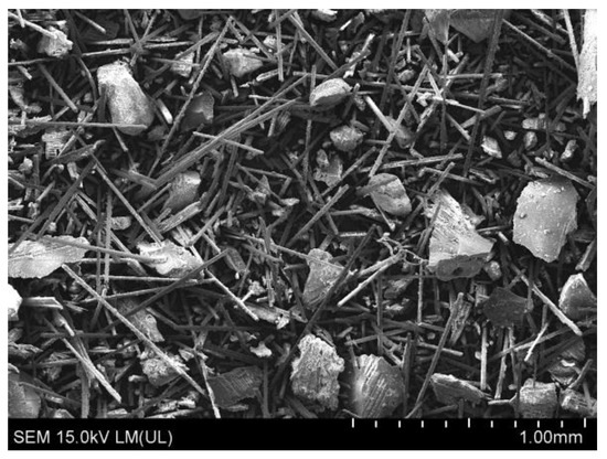
Figure 1.
Image of shredded WTB dust fraction.
2.2. Apparatus
In order to prepare, modify, and investigate the studied composites, specialized instruments were used. The mixing of the composite components was carried out using a mechanical stirrer type Disperlux (ProLab, Gliwice, Poland). The irradiation of the epoxy/DF composites was performed using a linear electron accelerator type Elektronika 10/10 (Institute of Nuclear Chemistry and Technology, Warsaw, Poland) with an electron energy of 10 MeV and a beam power of 10 kW. The thermal properties of the materials were determined with a differential scanning calorimeter type DSC 1 STARe System (Mettler Toledo, Greifensee, Switzerland), while their thermal stability was measured using a thermogravimetric analyzer type 209 F1 Libra (Netzsch, Selb, Germany). The morphology of the fracture surfaces and the interfacial adhesion between composite components were examined using a scanning electron microscope type Hitachi SU8010 (Hitachi, Tokyo, Japan). The specific density of the composites was measured with a helium pycnometer type Ultrapycnometer 1000 (Quantachrome Instruments, Boynton Beach, FL, USA). Changes in hardness were evaluated using a Shore D hardness tester type D (Zwick, Ulm, Germany), while the mechanical properties under static three-point bending were tested with a tensile testing machine type TIRAtest 27025 (TIRA Maschinenbau GmbH, Schalkau, Germany). Finally, the impact strength was determined using a pendulum impact tester type IMPats-15 (ATS FAAR, Novegro-Tregarezzo, Italy) in accordance with the Izod impact method.
2.3. Sample Preparation
In this study, two types of composite materials were manufactured. In the first step, the epoxy resin was thoroughly mixed with the curing agent Z1 at a weight ratio of 12:100 (Z1:EPO). In the second step, 20 wt% DF was added before the resin became fully cured, obtaining in this way the first composite (E). The second composite (ET) was obtained by adding 5% TAIC to the first composite before its curing. All components were mixed in a reactor using a mechanical stirrer operating at 1000 rpm for 10 min. Next, the obtained mixtures in the liquid state were degassed. In the final step, the epoxy composites were cast into a Teflon mold with dimensions of 10 mm × 4 mm × 80 mm and allowed to cure at room temperature (25 °C) for 24 h.
Both composites (E and ET) were subjected to electron irradiation at doses of 40, 80, 120, and 160 kGy. The irradiation process was performed using a linear accelerator generating a scanned electron beam with an energy of 10 MeV and a power of 10 kW. The maximum single irradiation dose was limited to 40 kGy due to the temperature increase observed in the material, which reached approximately 4–7 °C for each 10 kGy dose. Because higher single doses lead to significant heating of the samples and may induce additional structural changes, the total irradiation doses were achieved by multiple exposures of 40 kGy. The time intervals between each dose fraction were determined based on the time needed to cool samples down after absorbing a 40 kGy dose. Dosimetry was carried out using a graphite calorimeter according to ISO/ASTM 51631-20e1. During irradiation, all samples were placed in aluminum containers forming single layers of up to 5 mm in thickness. The containers were transported on a conveyor belt moving at a constant speed of 0.2 m/min beneath the accelerator scanner. The conveyor speed was adjusted according to the radiation dose absorbed by the modified polymer material. Irradiated samples were denoted as E40, E80, E120, E160, ET40, ET80, ET120, and ET160, where E means epoxy/DF composite, ET, epoxy/DF composite containing TAIC, and the numbers indicate the appropriate dose. Non-irradiated reference samples were denoted with symbols E0 and ET0. The symbols and composition (wt%) of the studied composites are summarized in Table 1.

Table 1.
Symbols and compositions of studied composites.
2.4. Research Methods
DSC measurements were conducted under a nitrogen atmosphere with a flow rate of 60 mL/min. The samples were sequentially heated from 20 to 220 °C at a rate of 10 °C/min, annealed at 220 °C for 3 min, cooled to 20 °C at 10 °C/min, and reheated to 220 °C at the same rate. The first and second heating cycles were used to evaluate the thermal properties of the tested samples. Samples of approximately 5–6 mg were taken from the central part of the bar-shaped specimen core for analysis. Thermogravimetric (TG) measurements were conducted within the temperature range of 30–900 °C under a nitrogen atmosphere at a heating rate of 10 °C/min. Samples of approximately 10 mg were placed in open platinum crucibles. The preparation of samples for TG was analogous to that for DSC measurements. The surface morphology of specimen fractures and phase boundary adhesion was examined using scanning electron microscopy (SEM) with a secondary electron (SE) detector at an accelerating voltage of 15 kV. Fracture surfaces were obtained by immersing the samples in liquid nitrogen for 15 min, followed by brittle fracture. Prior to observation, all samples were sputter-coated with an 11 nm layer of gold. Density was determined using the pycnometric method in accordance with the PN-EN ISO 1183-3:2003 standard. Ten independent measurements were performed for each sample. Hardness was determined by the Shore method following the PN-EN ISO 868:2005 standard. Measurements were taken at three points on four randomly selected specimens, and the final value was calculated as the arithmetic mean of twelve individual measurements. Flexural modulus (Ef), flexural strength (σfM), and deflection (s) were determined using a three-point bending test at a deflection rate of 5.0 mm/min, in accordance with the PN-EN ISO 178:2011 standard. Five measurements were conducted for each sample. The impact strength (aiN) was assessed following the PN-EN ISO 180:2023 standard. For each material, ten specimens were tested, and the average values were calculated.
3. Results and Discussion
3.1. DSC Analysis
The DSC results are shown in Figure 2 and summarized in Table 2. Figure 2 shows only example DSC curves, i.e., for samples E0, E160, ET0, and ET160. The curves of the remaining samples have a similar shape, so they are not shown. In Table 2, there are values of the glass transition temperature determined in the first (Tg1) and second (Tg2) heating cycle, the crosslinking temperature (Tc-l), and the enthalpy (ΔH) of this process.
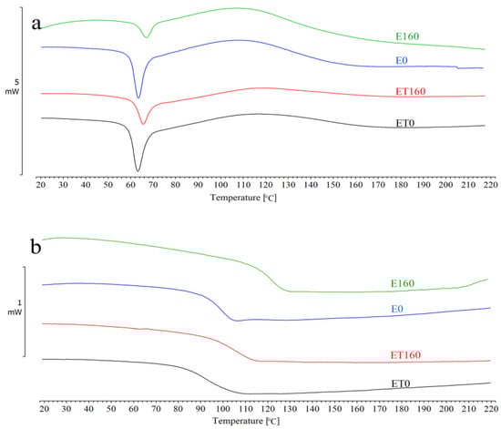
Figure 2.
DSC results for E0, E160, ET0, and ET160 samples: (a) first heating; (b) second heating.
Table 2.
Phase transition temperatures and enthalpy of the studied samples.
In Figure 2a, a large enthalpy relaxation peak is visible in the range of ca. 63–67 °C. Before reaching the minimum temperature of this peak, a glass transition occurs at a temperature ranging from 59 to 63 °C. This temperature is about 35 °C higher compared to the curing temperature (25 °C), which usually occurs in this type of material. This difference indicates that the resin, after curing at room temperature, will undergo further and slow curing over time due to the continuous reaction in the glassy state. Figure 2a also shows that after exceeding the Tg value, a broad exothermic peak immediately appears, indicating further crosslinking reactions until the complete curing of the resin. This peak reaches its maximum in the temperature range of 110 to 117 °C. This reaction is associated with additional segmental mobility of the macromolecules, as a result of which the resin should continue to cure with increasing temperature. Importantly, the presence of such residual exotherm also indicates incomplete resin curing.
In Figure 2b, only the glass transition (Tg2) is visible at a temperature in the range of ca. 100–120 °C. The 20 °C difference results from the use of different radiation doses. The lack of residual exotherm and almost twice as high Tg2 values compared to Tg1 values indicate complete curing of the resin. Therefore, based on the comparison of the DSC results from the first and second heating cycles, it can be stated that the resin was not fully cured at room temperature. Furthermore, the applied radiation did not significantly affect the increase in the degree of its curing.
The data in Table 2 also indicate that with increasing radiation dose, Tg1 increased by a maximum of about 3–4 °C for both E and ET type samples. In contrast, Tg2 increased by a maximum of 22 °C for E-type samples and by 11 °C for ET-type samples. It can be concluded that although radiation did not significantly affect the glass transition temperature of the material cured at room temperature, it had a significant impact on the glass transition temperature of the fully cured material. Moreover, the TAIC used in the study did not affect the crosslinking of the investigated resins. The compound rather showed a clear plasticizing effect; therefore, the glass transition temperatures of the ET-type samples were lower than those of the E-type samples. From a practical standpoint, using a 25–curing temperature for the studied material will result in an under-cured metastable network. If this type of material is exposed to temperatures higher than ca. 60 °C during use, post-curing can occur, and the properties would change. For the samples studied, the DSC method showed increases in Tg associated with post-curing (from ca. 60 to ca. 120 °C) [34].
3.2. TG Analysis
The TG curves of E and ET type samples are shown in Figure 3. Numerical values of mass loss temperatures 1% (T1%), 2% (T2%), 5% (T5%), and 10% (T10%), as well as the maximum decomposition rate temperature (Tmax.), are summarized in Table 3. It follows from Figure 3 that all samples had the same thermal stability. The temperature of their maximum decomposition rate was in the range of ca. 368–375 °C. Significant changes can only be observed by analyzing the temperature values at mass losses from 1 to 10%. This is especially visible when comparing the temperature values of type E samples with the corresponding type ET samples. The differences in these temperatures are shown in Figure 4. From the data compiled in Table 3 and in Figure 4, it follows that samples containing TAIC had significantly lower values of mass loss temperatures in the range from 1 to 10% compared to samples without this compound. The differences in temperature T2% were even more than 100 °C, and for higher mass losses, they decreased, i.e., they were 10–36 °C for 5% mass loss and 2–8 °C for 10% mass loss. The largest differences (observed for T2%) may result from the fact that TAIC begins to decompose at a temperature of ca. 150 °C. Therefore, the highest rate of its decomposition was observed at temperatures ranging from 216 to 248 °C (Table 3).
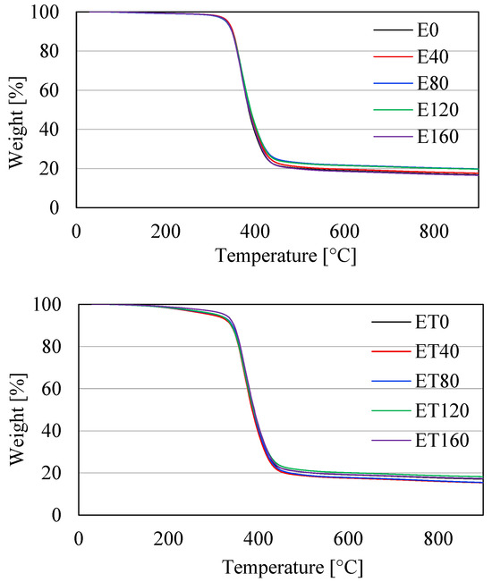
Figure 3.
TG results for samples of types E (thermogram above) and ET (thermogram below).
Table 3.
Summary of numerical values of temperatures for 1, 2, 5, 10% mass lost and Tmax. of the studied samples.
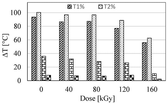
Figure 4.
Differences in temperatures T1%, T2%, T5%, and T10% between samples of types E and ET.
It is noteworthy that the values of T2%, as well as T5% and partially T10% of ET-type samples, increased with increasing radiation dose, which indicates partial crosslinking of the material in the presence of TAIC. The maximum increase was 31 °C for T2%. This statement does not apply to E-type samples, for which the increase in radiation dose did not affect their thermal stability, especially in the range of mass loss below 10%. Importantly, the TAIC decomposition observed in the TG investigation indicates that it participated in the crosslinking of the resin only to a minimal extent. The predominant amount of this compound, which did not form crosslinking bonds, exhibited only a plasticizing effect. This statement is consistent with the results of DSC studies, where a significant decrease in the Tg values of samples containing TAIC was observed. Furthermore, a similar plasticizing effect was also observed and confirmed in other studies [35,36].
3.3. Microscopic Investigations
Microscopic examinations of the samples, presented in Figure 5, exhibit brittle fracture behavior with a distinct dispersed phase. They show a continuous polymer matrix, in which there were glass fibers and resin particles derived from the milling of wind turbine blades. Generally, the structure of all samples was the same, and the adhesion at the phase boundary was very good. No free spaces between the polymer matrix and the dispersed phase were observed. The only difference that could be observed between the structure of E- and ET-type samples was the presence in the latter of a small number of round and shallow indentations (marked with arrows). These are probably closed gas cells formed as a result of the partial decomposition of TAIC during the exothermic resin curing process. Another reason for their occurrence could be insufficient degassing of the resin before curing. Their diameter was ca. 30–70 µm. The presence of this type of cells had to be related to TAIC because this type of indentation was not observed in the structure of E-type samples. In addition, other types of indentations with a regular shape and diameter were visible in the structure of both types of samples. These were craters in which the fibers were originally located. The observed craters did not represent material defects but rather replicas of the opposite fracture surface of the sample. Moreover, based on the SEM images, no effect of electron radiation on the structure of individual samples was found.
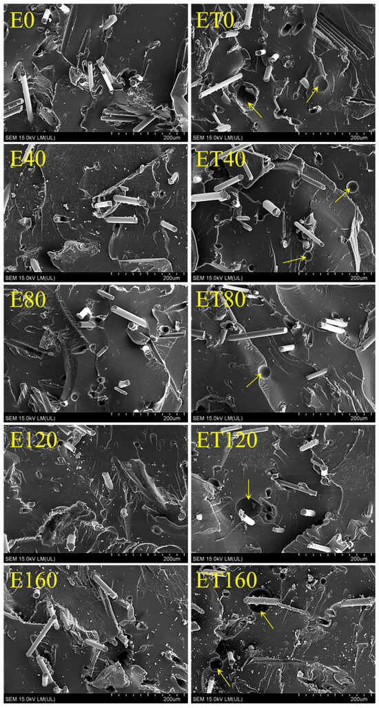
Figure 5.
SEM analysis of the studied samples.
3.4. Density
Density studies were performed due to the results of microscopic observations. The indentations visible in the SEM images of ET-type samples were confirmed by the reduced density values of these samples (Figure 6). All ET-type samples exhibited significantly lower density compared to E-type samples. The largest difference was observed between samples E and ET irradiated with a dose of 40 kGy. Importantly, no effect of electron radiation on changes in the density values of E- and ET-type samples was found. The density of E and ET samples was ca. 1.21 and 1.15, respectively. The results indicated that the density values of the individual E-type samples were not significantly different from one another, as confirmed by their confidence intervals. The same applies to ET-type samples. Thus, it was confirmed that radiation does not affect the decomposition of TAIC in the resin. Therefore, the indentations visible in the SEM images of the fracture surfaces of ET-type samples result from the reasons described in Section 3.3.
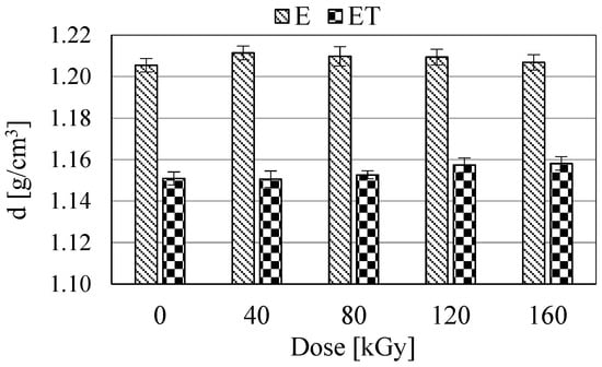
Figure 6.
Density (d) of the studied samples.
3.5. Mechanical Properties
3.5.1. Hardness
The plasticization effects of the resin by TAIC, as demonstrated in the thermal analysis, should be visible in the hardness test of the obtained materials. The performed measurements (Figure 7) clearly indicated the occurrence of this effect. The lowest hardness was exhibited by the ET0 sample (hardness value 75.7). Its hardness value increased rapidly with increasing radiation dose. However, even the highest dose did not cause a large enough increase in the hardness of the ET0 sample to make it harder than the corresponding sample without TAIC. With increasing radiation dose, the hardness of the E-type samples also increased, but this increase was slow and very small. The maximum hardness value (almost 80) was observed in the E160 sample. However, due to the relatively large confidence intervals observed in Figure 7, it cannot be conclusively stated that the radiation treatment influences the hardness of these samples. The greatest difference in hardness of the samples occurred between the non-irradiated samples E and ET. Furthermore, the data in Figure 7 show that as the dose increased, the differences in hardness between the E and ET samples decreased and, for the highest doses (120 and 160 kGy), did not differ significantly from each other.
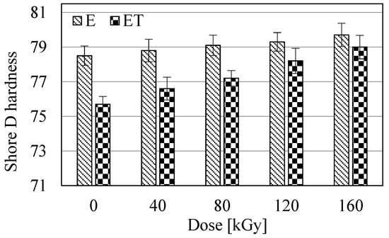
Figure 7.
Hardness of the studied samples.
3.5.2. Three-Point Bending
The results of the mechanical properties determined from the static three-point bending tests are presented in Table 4. Relations of σ = f(s) for E0, E80, E160, ET0, ET80, and ET160 samples, concerning the static three-point bending tests, are illustrated in Figure 8. The courses of the remaining samples are similar to those presented and are not shown here.
Table 4.
Test results of mechanical properties during static three-point bending.
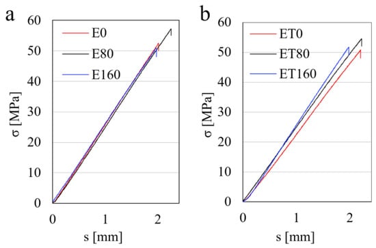
Figure 8.
Relationship σ = f(s) for samples E0, E80, E160 (a) and samples ET0, ET80, and ET160 (b).
It follows from Table 4 that the flexural strength of samples containing TAIC was lower compared to those without TAIC. This is related to the plasticization effect, which was discussed earlier. Furthermore, with an increase in the radiation dose to 80 kGy, the values of σfM increased. Their maximum values were 57.7 MPa and 53.1 MPa for E80 and ET80 samples, respectively. Further increase in the dose caused a decrease in σfM, which was mainly due to the earlier breaking of the sample in the rectilinear area [σ = f(s)]. Thus, doses of 120 or 160 kGy reduced the deflection (s) values of the studied samples compared to those irradiated with 80 kGy. It can be said that the samples became more brittle, which was also confirmed in dynamic mechanical tests (Figure 9). The flexural modulus of E-type samples practically did not change under the influence of radiation and was ca. 4 GPa. Only the E160 sample was characterized by a slightly lower value of modulus (3.8 GPa), which may result from the occurrence of the radiation degradation process of the resin. All ET-type samples had lower modulus values compared to most E-type samples, which is a result of matrix plasticization. The non-irradiated sample ET0 was characterized by the smallest modulus value (below 3.7 GPa). In the case of ET-type samples, the plasticization effect clearly decreased with increasing radiation dose. This is clearly visible in Figure 8b, where the individual curves had different slope angles. This indicated a decrease in the amount of plasticizer, which, partially, under the influence of radiation, should form crosslinking bonds.
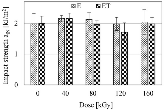
Figure 9.
Izod impact strength (aiN) of the studied samples.
3.5.3. Izod Impact Strength
The results of the Izod impact strength investigations are presented in Figure 9. The studies indicate that the aiN values of most E and ET type samples did not differ significantly from each other. Minimal difference is observed only between samples E40 and ET120. Furthermore, all samples exhibited a similar impact strength of ca. 2 kJ/m2. Thus, these were quite brittle materials, and electron radiation and TAIC did not affect changes in their impact strength. From the studies presented in Figure 9, as well as previous studies, it follows that the investigated samples broke quite easily, regardless of whether they were subjected to static or dynamic loading.
4. Conclusions
Studies on the radiation treatment of an epoxy resin composite containing 20 wt% dusty fiber fractions indicated several important issues. First of all, electron radiation had a small effect on the changes in the properties of the investigated composite. With increasing dose, its glass transition temperature, hardness, and partially flexural strength (up to 80 kGy) slightly increased, i.e., by 3.7 °C, 1.2, and 4.6 MPa, respectively. Greater changes in the properties of the composite were observed after adding TAIC. It demonstrated good plasticizing effects, which allowed for the observation of a decrease in the values of some parameters, such as glass transition temperature (by 1.1 °C), initial decomposition temperature of the material (by 35.9 °C), hardness (by 2.8), or flexural modulus (by 352 MPa). However, under the influence of electron radiation, this compound only slightly promoted the crosslinking of the resin. It still exhibited a plasticizing effect even at the highest radiation doses. Importantly, it was found that various doses could be used to regulate the degree of plasticization of the investigated composite, and thus some of its properties. Furthermore, the use of recycled wind turbine blade fibers in such a modified material is one way to manage waste from used wind turbine blades.
Author Contributions
Conceptualization, R.M. and D.M.; methodology, R.M., D.M. and U.G.; formal analysis, R.M. and V.K.; investigation, R.M., D.M., V.K. and D.K.; resources, R.M., D.M. and U.G.; writing—original draft preparation, R.M.; writing—review and editing, D.M. and V.K.; project administration, R.M. All authors have read and agreed to the published version of the manuscript.
Funding
This research received no external funding.
Data Availability Statement
The original contributions presented in the study are included in the article; further inquiries can be directed to the corresponding author.
Conflicts of Interest
The authors declare no conflicts of interest.
References
- Boyano, A.; Lopez-Guede, J.M.; Torre-Tojal, L.; Fernandez-Gamiz, U.; Zulueta, E.; Mujika, F. Delamination fracture behavior of unidirectional carbon reinforced composites applied to wind turbine blades. Materials 2021, 14, 593. [Google Scholar] [CrossRef]
- Ding, A.; Wang, J.; Ni, A.; Li, S. Assessment on the ageing of sandwich composites with vinylester-based composite faces and PVC foam core in various harsh environments. Compos. Struct. 2019, 213, 71–81. [Google Scholar] [CrossRef]
- Rani, M.; Choudhary, P.; Krishnan, V.; Zafar, S. A review on recycling and reuse methods for carbon fiber/glass fiber composites waste from wind turbine blades. Compos. Part B 2021, 215, 108768. [Google Scholar] [CrossRef]
- Joustra, J.; Flipsen, B.; Balkenende, R. Structural reuse of high end composite products: A design case study on wind turbine blades. Resour. Conserv. Recycl. 2021, 167, 105393. [Google Scholar] [CrossRef]
- Rahimizadeh, A.; Kalman, J.; Fayazbakhsh, K.; Lessard, L. Recycling of fiberglass wind turbine blades into reinforced filaments for use in Additive Manufacturing. Compos. Part B 2019, 175, 107101. [Google Scholar] [CrossRef]
- Pickering, S.J. Recycling technologies for thermoset composite materials-current status. Compos. Part A 2006, 37, 1206–1215. [Google Scholar] [CrossRef]
- Pimenta, S.; Pinho, S.T. Recycling carbon fibre reinforced polymers for structural applications: Technology review and market outlook. Waste Manag. 2011, 31, 378–392. [Google Scholar] [CrossRef]
- Wei, Y.; Hadigheh, S.A. Development of an innovative hybrid thermo-chemical recycling method for CFRP waste recovery. Compos. Part B 2023, 260, 110786. [Google Scholar] [CrossRef]
- Jensen, J.P.; Skelton, K. Wind turbine blade recycling: Experiences, challenges and possibilities in a circular economy. Renew. Sustain. Energy Rev. 2018, 97, 165–176. [Google Scholar] [CrossRef]
- Mamanpush, S.H.; Li, H.; Englund, K.; Tabatabaei, A.T. Extruded fiber-reinforced composites manufactured from recycled wind turbine blade material. Waste Biomass Valorization 2020, 11, 3853–3862. [Google Scholar] [CrossRef]
- Beauson, J.; Laurent, A.; Rudolph, D.P.; Jensen, J.P. The complex end-of-life of wind turbine blades: A review of the European context. Renew. Sustain. Energy Rev. 2022, 155, 111847. [Google Scholar] [CrossRef]
- Sakellariou, N. Current and potential decommissioning scenarios for end-of-life composite wind blades. Energy Syst. Energy Syst. 2018, 9, 981–1023. [Google Scholar] [CrossRef]
- Beauson, J.; Madsen, B.; Toncelli, C.; Brøndsted, P.; Bech, J.I. Recycling of shredded composites from wind turbine blades in new thermoset polymer composites. Compos. Part A 2016, 90, 390–399. [Google Scholar] [CrossRef]
- Mamanpush, S.H.; Li, H.; Englund, K.; Tabatabaei, A.T. Recycled wind turbine blades as a feedstock for second generation composites. Waste Manag. 2018, 76, 708–714. [Google Scholar] [CrossRef]
- Correia, J.R.; Almeida, N.M.; Figueira, J.R. Recycling of FRP composites: Reusing fine GFRP waste in concrete mixtures. J. Clean. Prod. 2011, 19, 1745–1753. [Google Scholar] [CrossRef]
- Yazdanbakhsh, A.; Bank, L.C.; Tian, Y. Mechanical processing of GFRP waste into large-sized pieces for use in concrete. Recycling 2018, 3, 8. [Google Scholar] [CrossRef]
- Pławecka, K.; Przybyła, J.; Korniejenko, K.; Lin, W.T.; Cheng, A.; Łach, M. Recycling of mechanically ground wind turbine blades as filler in geopolymer composite. Materials 2021, 14, 6539. [Google Scholar] [CrossRef] [PubMed]
- Khalid, M.Y.; Arif, Z.U.; Hossain, M.; Umer, R. Recycling of wind turbine blades through modern recycling technologies: A road to zero waste. Renew. Energy Focus 2023, 44, 373–389. [Google Scholar] [CrossRef]
- Błędzki, A.; Urbaniak, M.; Adamcio, A.; Sobczyk, M.; Demski, S.; Boczkowska, A.; Seidlitz, H.; Köhler, M. Reusing and recycling of composite wind turbine blades. A review of current practices and prospects. Part 3. Various proposals offered by small and middle companies. Przem. Chem. 2024, 103, 241–250. [Google Scholar] [CrossRef]
- Smoleń, J.; Olesik, P.; Jała, J.; Adamcio, A.; Kurtyka, K.; Godzierz, M.; Kozera, R.; Kozioł, M.; Boczkowska, A. The use of carbon fibers recovered by pyrolysis from end-of-life wind turbine blades in epoxy-based composite panels. Polymers 2022, 14, 2925. [Google Scholar] [CrossRef]
- Cheng, X.; Du, B.; He, J.; Long, W.; Su, G.; Liu, J.; Fan, Z.; Chen, L. A Review of thermoplastic composites on wind turbine blades. Compos. Part B 2025, 299, 112411. [Google Scholar] [CrossRef]
- Chen, C.; Anderson, D.P. E-beam-cured layered-silicate and spherical silica epoxy nanocomposites. J. Appl. Polym. Sci. 2007, 106, 2132–2139. [Google Scholar] [CrossRef]
- Lopata, V.J.; Saunders, C.B.; Singh, A.; Janke, C.J.; Wrenn, G.E.; Havens, S.J. Electron-beam-curable epoxy resins for the manufacture of high-performance composites. Radiat. Phys. Chem. 1999, 56, 405–415. [Google Scholar] [CrossRef]
- Chen, J.H.; Johnston, A.; Petrescue, L.; Hojjati, M. Investigation of influence factors in electron beam curing of epoxy resins using a calorimetry technique. J. Appl. Polym. Sci. 2009, 111, 2318–2327. [Google Scholar] [CrossRef]
- Raghavan, J. Evolution of cure, mechanical properties, and residual stress during electron beam curing of a polymer composite. Compos. Part A 2009, 40, 300–308. [Google Scholar] [CrossRef]
- Kikkawa, J.; Nii, A.; Sakaniwa, Y.; Kon, N.; Sakamaki, M.; Ohashi, T.; Nita, N.; Harano, K.; Kimoto, K. Fast electron damage mechanism of epoxy resin studied by electron energy loss spectroscopy and electron diffraction. J. Chem. Phys. 2023, 159, 174708. [Google Scholar] [CrossRef]
- Cole, K.C.; Ton-That, M.T.; Johnston, A.; Hojjati, M.; Valcourt, K.; Lopata, V.J. Investigations into the mechanism of electron-beam curing of an epoxy resin. In Fourth Canada-Japan Workshop on Composites, 1st ed.; Hoa, S.V., Ed.; CRC Press: Boca Raton, FL, USA, 2002; pp. 43–52. [Google Scholar]
- Wolff-Fabris, F.; Altstädt, V. Electron Beam Curing of Epoxy Composites. In Epoxy Polymers: New Materials and Innovations, 1st ed.; Pascault, J.P., Williams, R.J.J., Eds.; Wiley-VCH: Weinheim, Germany, 2010; pp. 253–269. [Google Scholar]
- Kang, P.H.; Park, J.S.; Nho, Y.C. Effect of electron beam and γ-ray irradiation on the curing of epoxy resin. Macromol. Res. 2002, 10, 332–338. [Google Scholar] [CrossRef]
- Sui, G.; Zhong, W.H.; Yang, X.P. The revival of electron beam irradiation curing of epoxy resin—Materials characterization and supportive cure studies. Polym. Adv. Technol. 2009, 20, 811–817. [Google Scholar] [CrossRef]
- Sui, G.; Zhang, Z.G.; Chen, C.Q.; Zhong, W.H. Analyses on curing process of electron beam radiation in epoxy resins. Mater. Chem. Phys. 2003, 78, 349–357. [Google Scholar] [CrossRef]
- Cong, L.; Guo, Z.; Zhang, X.; Li, H.; Jiang, H.; Jing, Y.; Yan, J.; Li, W.; Jang, J.; Li, X. Effect of Electron Beam Irradiation on the Percentage Loss of Tensile Modulus of Epoxy Polymer. Polymers 2025, 17, 447. [Google Scholar] [CrossRef] [PubMed]
- Nishitsuji, D.A.; Marinucci, G.; Evora, M.C.; e Silva, L.G.D.A. Study of electron beam curing process using epoxy resin system. Nucl. Instrum. Methods Phys. Res. Sect. B 2007, 265, 135–138. [Google Scholar] [CrossRef]
- Dyakonov, T.; Chen, Y.; Holland, K.; Drbohlav, J.; Burns, D.; Vander Velde, D.; Seib, L.; Soloski, E.J.; Kuhn, J.; Mann, P.J.; et al. Thermal analysis of some aromatic amine cured model epoxy resin systems—I: Materials synthesis and characterization, cure and post-cure. Polym. Degrad. Stab. 1996, 53, 217–242. [Google Scholar] [CrossRef]
- Malinowski, R.; Rytlewski, P.; Janczak, K.; Raszkowska-Kaczor, A.; Moraczewski, K.; Stepczyńska, M.; Żuk, T. Studies on functional properties of PCL films modified by electron radiation and TAIC additive. Polym. Test. 2015, 48, 169–174. [Google Scholar] [CrossRef]
- Rusli, A.; Raffi, N.S.M.; Ismail, H. Solubility, miscibility and processability of thermosetting monomers as reactive plasticizers of polyetherimide. Procedia Chem. 2016, 19, 776–781. [Google Scholar] [CrossRef][Green Version]


Disclaimer/Publisher’s Note: The statements, opinions and data contained in all publications are solely those of the individual author(s) and contributor(s) and not of MDPI and/or the editor(s). MDPI and/or the editor(s) disclaim responsibility for any injury to people or property resulting from any ideas, methods, instructions or products referred to in the content. |
© 2025 by the authors. Licensee MDPI, Basel, Switzerland. This article is an open access article distributed under the terms and conditions of the Creative Commons Attribution (CC BY) license (https://creativecommons.org/licenses/by/4.0/).