Article

Carbon Fiber Recycling from Waste CFRPs via Microwave Pyrolysis: Gas Emissions Monitoring and Mechanical Properties of Recovered Carbon Fiber

1
Department of Molecular Science and Engineering, Research and Development Center for Smart Textile Technology, National Taipei University of Technology, Taipei 106, Taiwan
2
Department of Chemical & Materials Engineering, Chung Cheng Institute of Technology, National Defense University, Taoyuan 335, Taiwan
3
System Engineering and Technology Program, National Chiao Tung University, Hsinchu 300, Taiwan
4
Department of Civil Engineering, National Taipei University of Technology, Taipei 106, Taiwan
5
Institute of Environmental Engineering and Management, National Taipei University of Technology, Taipei 106, Taiwan
6
LI-COR Biosciences, Lincoln, NE 68504, USA
*
Author to whom correspondence should be addressed.
These authors contributed equally to this work.
Fibers 2024, 12(12), 106; https://doi.org/10.3390/fib12120106
Submission received: 11 October 2024 / Revised: 4 November 2024 / Accepted: 26 November 2024 / Published: 5 December 2024

Abstract

:
Disposing of carbon fiber-reinforced polymers (CFRPs) has become a pressing issue due to their increasing application across various industries. Previous work has focused on removing silane coupling agent residues on recovered carbon fibers via microwave pyrolysis, making them suitable for use in new materials. However, the mechanical performance and structural characteristics of these fibers have not been fully reported. This study investigates the time–temperature curves of CFRPs treated through microwave pyrolysis and analyzes the mechanical and structural properties of silane-controllable recovered carbon fibers. Additionally, emissions—including carbon monoxide, carbon dioxide, and particulate aerosols—were measured using handheld monitors and thermal desorption–gas chromatography/mass spectrometry to determine the composition of fugitive gases around the microwave pyrolysis system. The pyrolysis process at 950 °C, with an additional 1 h holding time, reduced the crystallite size from 0.297 Å to 0.222 Å, significantly enhancing tensile strength (3804 ± 713 MPa) and tensile modulus (200 ± 13 GPa). This study contributes to more sustainable CFRP waste treatment and highlights the potential for reusing high-quality carbon fibers in new applications, enhancing both environmental and worker safety.

1. Introduction

Carbon fiber-reinforced polymers (CFRPs) are composite materials made by reinforcing thermosetting polymer matrices, such as epoxy resin, with silane-pretreated carbon fibers (CFs) [1,2]. These materials offer several advantages, including low density, high strength-to-weight ratio, excellent elastic modulus, stiffness, thermal stability, electrical conductivity, and remarkable resistance to corrosion and chemical degradation [3]. These properties make CFRPs ideal for applications requiring strong yet lightweight materials.
Due to these advantages, CFRPs have increasingly replaced conventional materials such as steel, aluminum, and alloys in industries such as automotive, wind energy, and aerospace [4,5,6,7]. By 2025, it is projected that the global market for CFRPs will exceed USD 25 billion annually, with an annual growth rate surpassing 10% [8,9,10]. However, the rapid expansion of CFRP applications has led to significant waste from both end-of-life (EOL) components and manufacturing processes, including offcuts, obsolete molds, and defective parts. This presents a major challenge for disposal and recycling in the composite industry [3,11].
In line with the “Cradle-to-Cradle” concept, which emphasizes transforming waste into valuable resources, CFRP waste can be recycled into valuable materials [11,12,13]. However, CFRPs, being thermosetting composites, do not decompose naturally due to the resin embedded within and on the surface of carbon fibers, which cannot be re-melted or re-shaped [14,15]. This poses a particular challenge for CFRP recycling. Conventional methods such as solvolysis, physical crushing, and thermal treatment also have limitations. For instance, solvolysis can recover clean fibers and recycle the thermoset matrix as monomer material, but it requires organic solvents such as ethanol or propanol, limiting its scalability and raising environmental concerns [8,16,17]. Meanwhile, physical crushing results in chopped fibers with residual resins, including silane, which are difficult to remove. These residues can hinder the performance of recycled fibers when used in new applications [18,19,20].
In contrast, pyrolysis has emerged as one of the most widespread recycling methods for CFRP waste, especially at an industrial scale [21,22]. Microwave pyrolysis, in particular, has shown potential for recovering clean carbon fibers from thermoset composite waste, reducing reaction time by 57% and increasing fiber recovery by 15% compared with conventional pyrolysis methods such as muffle furnaces [23]. In this process, CFRP waste is heated in a controlled environment (typically a nitrogen atmosphere) at temperatures between 450 °C and 700 °C [22,24,25]. Pyrolysis converts the resin into pyrolytic gas, oil, and solid char. The liquid pyrolytic products generally contain phenols, aromatics, hydrocarbons, amines, acids, and other substances, which can be collected and reused as valuable chemicals [26,27].
Despite the growing adoption of pyrolysis, little work has been done to fully understand the emissions generated during CFRP waste pyrolysis, particularly with regard to carbon monoxide (CO), carbon dioxide (CO2), particle emissions (aerosols), and the composition of fugitive gas emissions around the pyrolysis system. Monitoring these emissions is crucial to ensuring the safety of both the operators and the environment for conducting environmental impact assessments in industrial applications [28,29].
In previous work, silane-controllable recovered carbon fibers (sc-rCFs) [30] were developed to enhance the use of recycled carbon fibers (rCFs) in suitable products [12,31,32,33] via microwave pyrolysis. However, the mechanical performance and structural characteristics of these fibers have not yet been fully reported. In this study, we further investigate the time-temperature curves during pyrolysis, along with the mechanical performance and structural properties of the recycled sc-rCFs. Additionally, a detailed composition of the derived gases of CO, CO2, and particle emissions (aerosols) were determined with fugitive gas emissions around the microwave pyrolysis system using handheld monitors, then analyzed through thermal desorption–gas chromatography/mass spectrometry (TD–GC/MS) and used with activated carbon flakes as sorbents to capture fugitive gases.

2. Materials and Methods

2.1. Materials

The CFRP waste from recycled bicycle frames, along with virgin carbon fibers (VCFs, Mitsubishi TR 50), was provided by Giant Manufacturing Co., Ltd. (Taichung, Taiwan) The waste was cut and crushed into sample sizes of approximately 90 mm × 90 mm × 4.5 mm using a plate-cutting and hydraulic press machine.

2.2. Pyrolysis

The pyrolysis process was conducted according to a previously reported method [30]. CFRP waste (10 g) was placed in a ceramic crucible and pyrolyzed at temperatures ranging from 350 to 950 °C in an air atmosphere. A muffle furnace (JH-5, Chromtech, Taipei, Taiwan, 1200 W), a microwave pyrolysis system (MILESTONE PYRO 260, Shelton, WA, USA, 1200 W, 2.45 GHz), and a thermogravimetric analyser (TGA, TG 209 F3, Netzsch, Germany) were utilized for the pyrolysis process.

2.3. Characterization

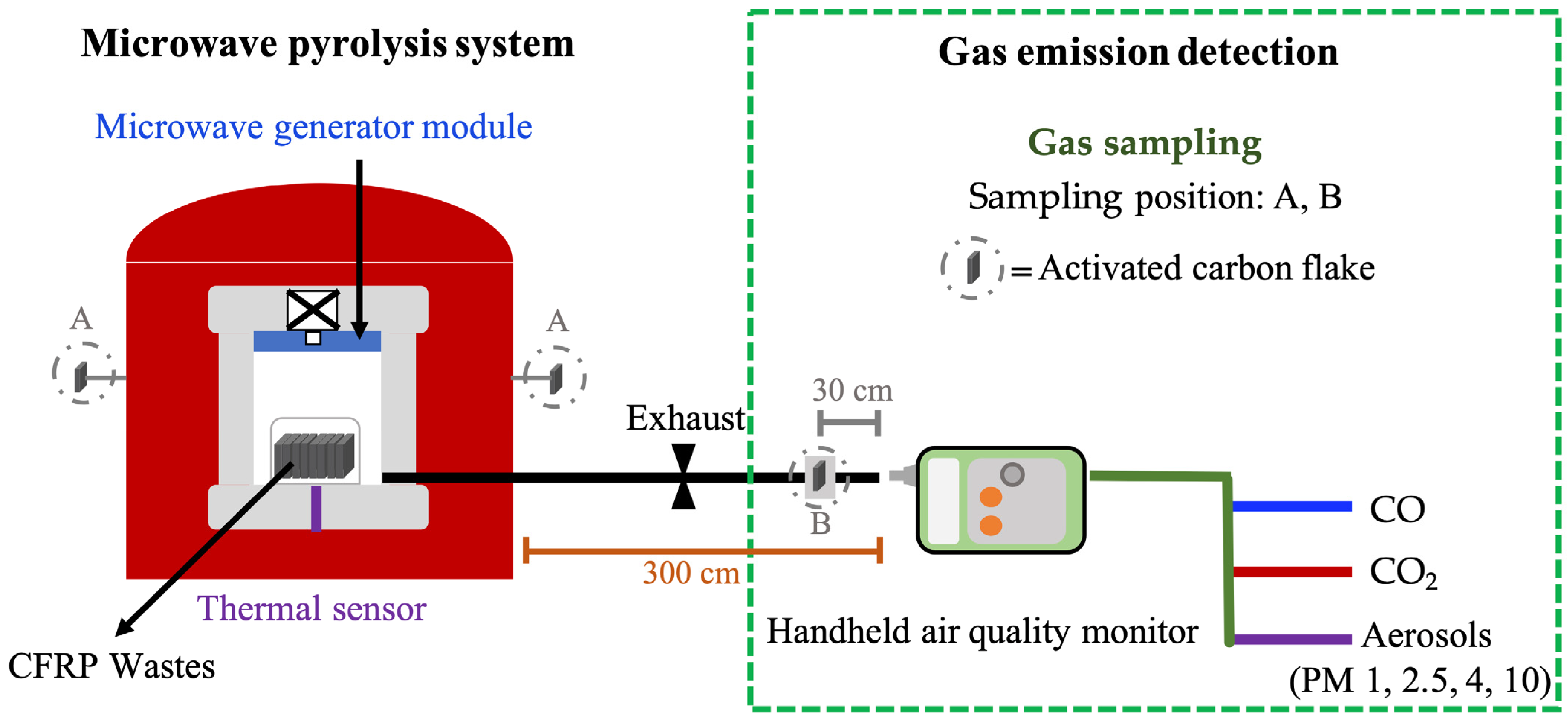
2.3.1. Emission Detection in the Pyrolysis Process of CFRP Waste

A handheld air quality monitor for carbon monoxide (CO) and carbon dioxide (CO2) (7515 Q-TRAK, TSI, Shoreview, MN, USA), along with another monitor for suspended particulates (Aerocet 831, MetOne, Grants Pass, OR, USA), were used to detect emissions during the pyrolysis process of CFRP waste. The monitors were positioned at the exhaust vent of the microwave pyrolysis system to collect emission data.

2.3.2. Composition of Gas Emissions in CFRP Waste Pyrolysis Process

The composition of gas emissions during the pyrolysis of CFRP waste was sampled using activated carbon flakes (1.5 × 1 cm, 0.5 ± 0.1 g), which were placed at two positions, as shown in Figure 1. After the pyrolysis process, the activated carbon flakes were collected, stored in vials, and later analyzed using thermal desorption–gas chromatography/mass spectrometry (TD–GC/MS).
The TD–GC/MS was carried out with a multi-shot pyrolyzer (EGA/PY-3030D, Frontier, Fukushima, Japan) coupled with an Agilent 7890 (Santa Clara, CA, USA) gas chromatograph and a 5975 MSD quadrupole mass spectrometer (Agilent, Santa Clara, CA, USA). The thermal desorption was performed under conditions ranging from 50 to 500 °C over 30 min, with a heating rate of 20 °C/min.
For the GC analysis, samples were injected into the column with a 1:40 split ratio. The analytical column used was a Frontier Ultra ALLOY EGA Capillary Tube (UADTM-2.5N: 0.25 mm i.d., 0.47 mm o.d., 2.5 m, Fukushima, Japan). The GC temperature program started at 45 °C (held for 1 min), followed by an increase at 10 °C/min to 250 °C, and a final increase at 5 °C/min to 270 °C, where it was held for 5 min [34,35].

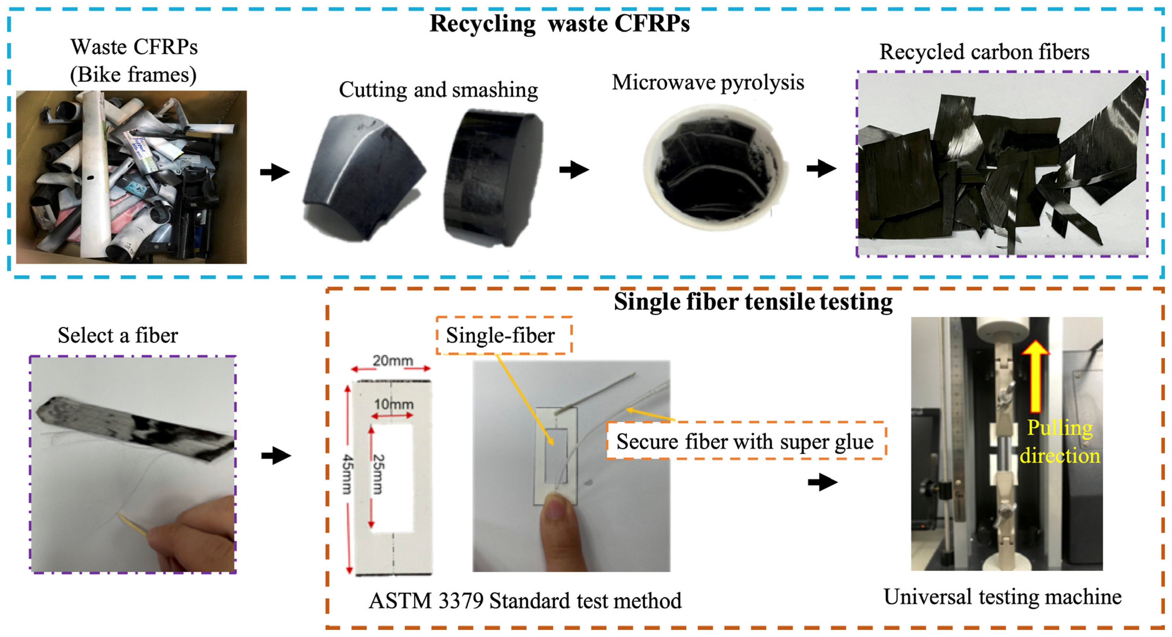
2.3.3. The Single-Fiber Tensile Properties of Recycled Fibers

The tensile properties of individual recycled carbon fibers were tested using a universal testing machine (QC-528M10, Cometech, Taichung, Taiwan) with a strain rate of 0.5 mm/min, following the ASTM 3379 standard test method [36], as shown in Figure 2. The fiber specimens, each 5 cm in length, were randomly selected from the recycled carbon fiber samples. For mounting, the fibers were fixed at the center of the tab with super glue and 1 mm Cartesian paper to ensure proper alignment during testing. Due to the high variability in the tensile strength of recycled carbon fibers, 50 tests were conducted on each group of recovered fibers to obtain an average tensile strength.

2.3.4. Fibers Structural Characterization

The carbon microcrystalline structures of the recycled carbon fiber were characterized using Raman spectroscopy (ACRON, UniNanoTech, Yongin-si, Gyeonggi-do, Republic of Korean), with a scanning range of 100 cm−1 to 3500 cm−1, and X-ray diffraction (XRD) analysis (PANalytical X’Pert3 Powder, Malvern Panalytical Empyrean, Almelo, The Netherlands), with a scan range of 10° to 80°.

3. Results and Discussion

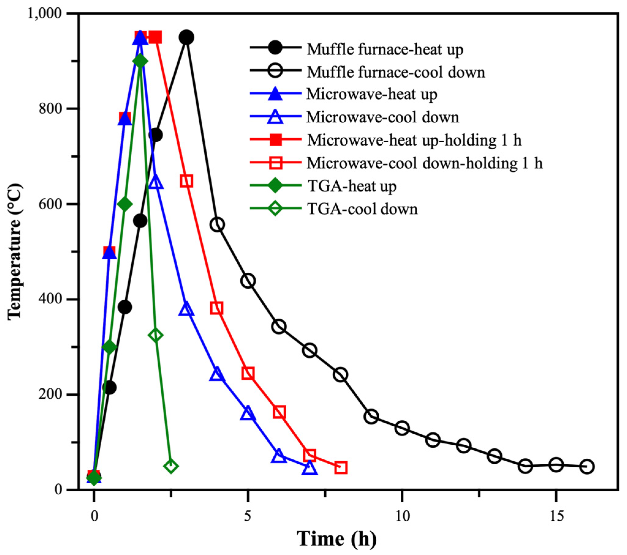
3.1. Time–Temperature Curves During the Pyrolysis of CFRP Waste

For CFRP waste recycling, our previous study reported on the pyrolysis process using both a laboratory-scale muffle furnace and a microwave pyrolysis system [30]. Both systems, the muffle furnace and microwave, can generate a maximum power of 1200 W and have similar capacities for handling CFRP waste. However, they exhibit different thermal profiles. Figure 3 shows the time–temperature curves during the pyrolysis process for recycling CFRP waste using both the muffle furnace and the microwave pyrolysis system, with a target temperature of 950 °C.
In the case of the muffle furnace, it took 3 h to heat from room temperature (RT) to the target temperature, corresponding to a heating rate of approximately 5 °C/min. Cooling down to RT took an additional 13 h. In contrast, the microwave pyrolysis system required only 1.5 h to reach the target temperature and 5.5 h to cool back down to RT. Even with an added 1 h holding time, the cooling rate followed the same thermal pattern.
Additionally, TGA was typically employed to investigate the thermal behaviour of CFRP during the pyrolysis process. The thermal profile of the TGA system showed that it took 1.5 h to reach the target temperature and only 1 h to cool back to RT. This faster cooling is due to the TGA’s small chamber size and an integrated cooling system.
Ultimately, the thermal profiles of all pyrolysis systems were compared, with the microwave system showing faster heating and improved efficiency compared with the muffle furnace. It is important to note, however, that heating rates depend heavily on system design and the size of the heating chamber. Nevertheless, these results serve as valuable references for researchers estimating the thermal performance of different pyrolysis systems.

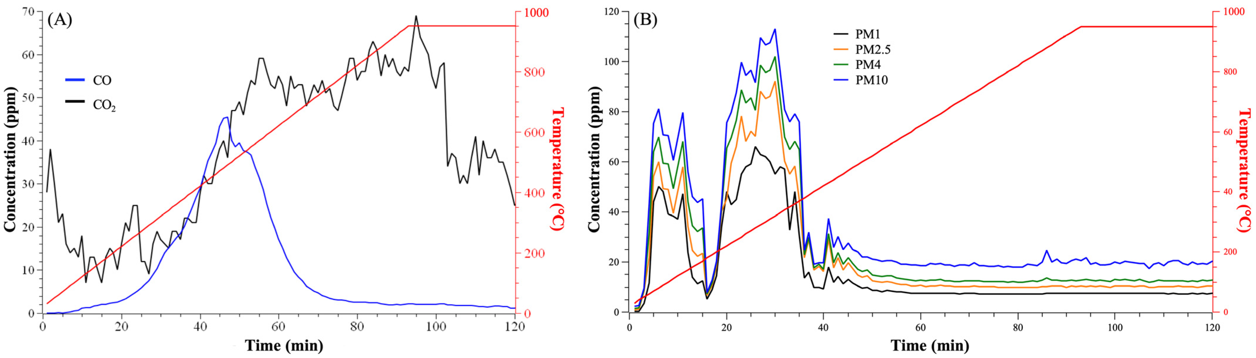
3.2. Emission in the Pyrolysis Process of CFRP Waste

3.2.1. Derived Gas

Understanding the emissions from CFRP waste pyrolysis is essential for ensuring the safety of both operators and the environment. During pyrolysis, decomposition primarily occurs within the epoxy resin matrix. As the temperature rises, the matrix may release small-molecule acid anhydrides, carbonyl groups, H2O, CO, CO2, and aromatic benzene compounds, depending on the type of epoxy resin used in CFRP manufacturing [37].
Figure 4A presents data collected from a handheld monitor placed at the exhaust vent of the microwave pyrolysis system during a 120 min pyrolysis process. In the first 50 min, the measured CO concentration increased from 0 ppm to 45 ppm as the temperature rose, peaking at around 500 °C. Subsequently, the CO concentration decreased from 45 ppm to 5 ppm over the next 20 min and remained stable for the rest of the data collection period.
Regarding CO2 emissions, the data show an initial peak of 40 ppm within the first 5 min (30 to 100 °C), followed by fluctuations over the next 25 min. Afterwards, the CO2 concentration rose to 60 ppm, stabilizing between 50 and 100 min (600 to 950 °C) into the pyrolysis process.
On the other hand, the particle emissions during the pyrolysis process are shown in Figure 4B. The emitted particle sizes were simultaneously monitored at four levels: PM1 (aerodynamic diameter < 1 μm), PM2.5 (<2.5 μm), PM4 (<4 μm), and PM10 (<10 μm). The results indicate that particle concentrations increased rapidly, peaking twice—once between 5 and 15 min and again between 20 and 35 min. The corresponding temperature ranges were 50 to 200 °C and 250 to 400 °C. The size distribution of the emitted particles showed that the highest concentrations, 80 and 110 μg/m3, were recorded for PM10, with approximately 60% of these emissions of particles smaller than PM1.
The air pollutants, including CO, CO2, and particle emissions, were predominantly emitted within the temperature range of 300 to 600 °C. This emission profile is attributed to resin decomposition in the CFRP waste, which contains approximately 60 wt% resin that decomposes between 330 and 650 °C. The double peak in aerosol emissions reflects the two stages of thermal decomposition observed in TGA analysis: the first stage occurs between 220 and 450 °C, and the second stage is between 475 and 550 °C, consistent with the resin decomposition behavior noted in previous studies [30].

3.2.2. Composition of Derived Gas Emissions

The composition of gas emissions generated during the pyrolysis of CFRP waste was analyzed using TD–GC/MS, with activated carbon serving as the sampling medium.
Table 1 shows the composition of derived gas emissions, sampled by activated carbon placed at two positions: Position A (near the microwave pyrolysis system) and Position B (at the exhaust vent).
The data indicate that toluene and octane were the primary compounds emitted at both locations. Other aromatic compounds, such as ethylbenzene, styrene, phenol, and tetrahydrofuran, were detected only at the exhaust vent of the pyrolysis system. These emissions are attributed to the decomposition of the epoxy resins in CFRP products, which generally contain aromatic chemicals such as bisphenol A and amine compounds, both of which have aromatic ring structures. During the pyrolysis of CFRP waste, the released components are typically classified as phenols, aromatics, hydrocarbons, amines, acids, and other substances [26,27].
The difference in emission profiles between the two sampling positions may be due to the sequential decomposition of compounds during CFRP pyrolysis and the adsorption limitations of activated carbon. At Position A, fugitive emissions such as toluene and octane may have saturated the activated carbon. In contrast, at Position B (the exhaust vent), there was sufficient space in the pipeline to accumulate decomposed compounds before they were absorbed by the activated carbon.
Compared with other studies that collected liquid pyrolytic products from the exhaust vent using solvent traps, such as chloroform [26,27], the TD–GC/MS analysis with activated carbon offers a solvent-free approach. This method provides a potentially effective way to estimate the composition of fugitive gas emissions around equipment and could be valuable for health impact assessments in industrial settings.

3.3. Properties of Recovered Carbon Fibers

In previous work [30], we recycled carbon fibers with varying silane content, referred to as silane-controllable recovered carbon fibers (sc-rCFs), using microwave pyrolysis with controlled temperatures, sourced from waste CFRPs in the bicycle industry. However, the mechanical performance and structural properties of these fibers were not fully reported in earlier studies.

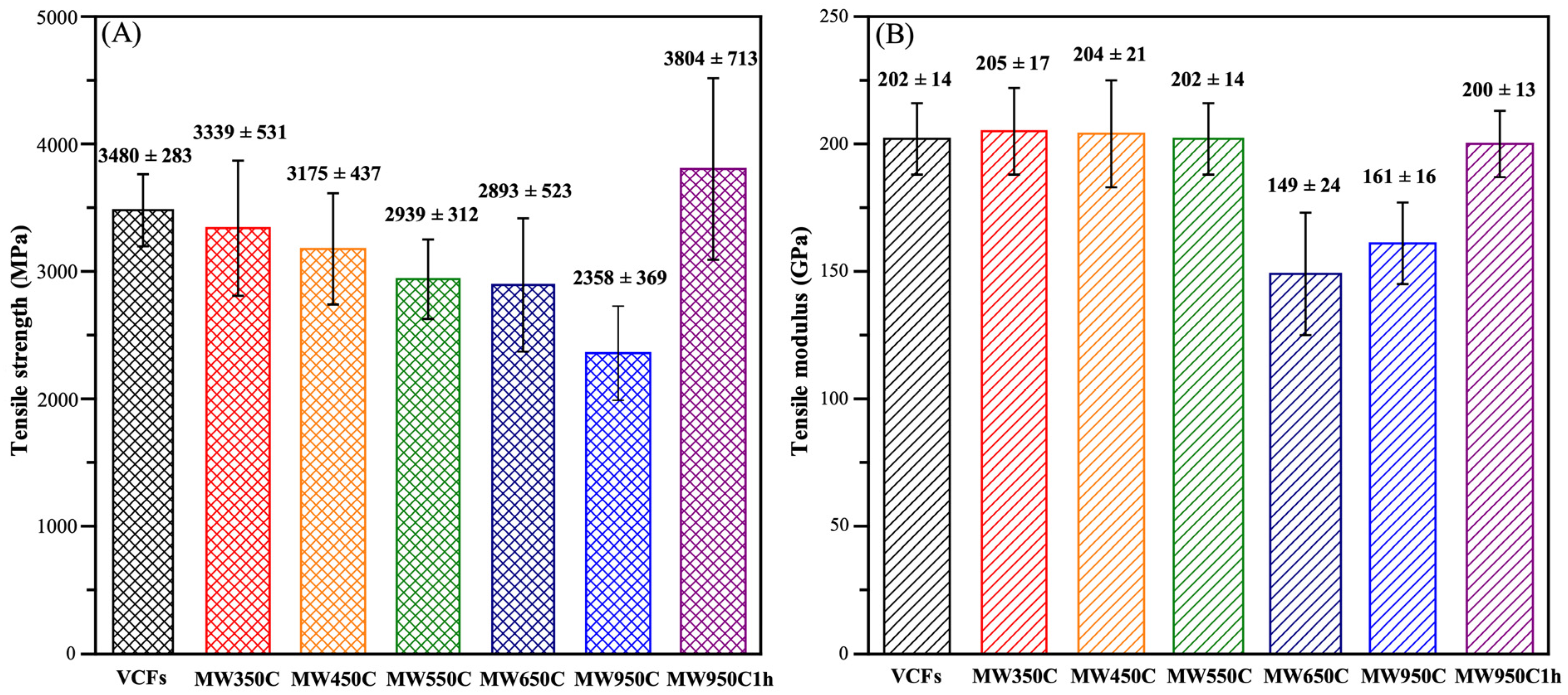
3.3.1. Mechanical Performance

The compression on the mechanical performance of VCFs and sc-rCFs with different pyrolysis temperatures at 350 °C (MW350C), 450 °C (MW450C), 550 °C (MW550C), 650 °C (MW650C), and 950 °C (MW950C) is shown in Figure 5.
In Figure 5A, the tensile strength of VCFs is measured at 3480 ± 283 MPa. For sc-rCFs, the tensile strength decreases as the pyrolysis temperature increases, with values ranging from 3339 ± 561 MPa to 2358 ± 369 MPa. However, when pyrolyzed at 950 °C for an additional hour (MW950C1H), sc-rCFs achieve a tensile strength of 3804 ± 713 MPa.
Figure 5B presents the tensile modulus results. VCFs have a tensile modulus of 202 ± 14 GPa. The tensile modulus of sc-rCFs remains around 200 GPa at pyrolysis temperatures of 350 °C, 450 °C, and 550 °C. The tensile modulus of sc-rCFs decreases to 149± 24 Gpa and 161 ±16 Gpa at pyrolysis temperatures of 650 °C and 950 °C, while it decreases to 149 ± 24 GPa and 161 ± 16 GPa at pyrolysis temperatures of 650 °C and 950 °C, respectively. With an additional hour of holding time at 950 °C, the tensile modulus of sc-rCFs significantly improves by 20%, reaching 200 ± 13 GPa.
As referenced in the SEM micrographs from our previous work [30], the primary differences were due to remaining resins and silane content at different pyrolysis temperatures, but significant surface defects on the fibers were not observed. Despite this, variations in pyrolysis temperature have measurable effects on the tensile strength and modulus of sc-rCFs. Further investigation using XRD and Raman spectroscopy is necessary to explore these changes.

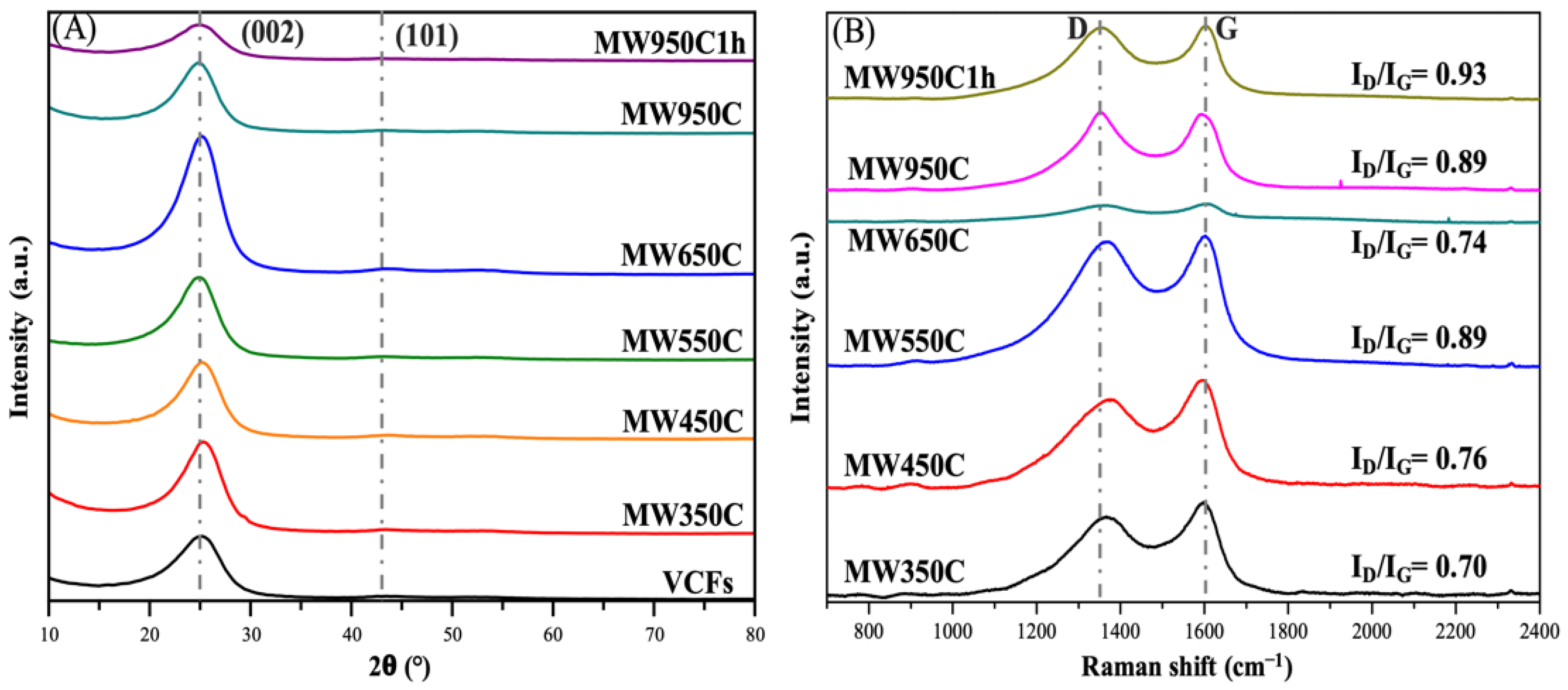
3.3.2. Structural Characterization

XRD and Raman spectroscopy were used to investigate the internal structure of the recycled carbon fibers (sc-rCFs). Figure 6A presents the XRD patterns of sc-rCFs recovered at different pyrolysis temperatures compared with VCFs. The intense (002) crystal plane at a 2θ value of 25.5° is typical of graphitic carbon, indicating the presence of a turbostratic graphitic structure in all the carbon fibers [38,39]. Using Scherrer’s equation [40,41], the apparent crystallite size (Lc) of all carbon fibers was calculated, as shown in Table 2.
The Lc for VCFs is 0.256 Å. In contrast, the Lc of sc-rCFs increased from 0.275 Å to 0.297 Å as the pyrolysis temperature increased from 350 °C to 950 °C. Additionally, when the pyrolysis process at 950 °C included an extra hour of holding time (MW950C1H), the Lc decreased significantly to 0.222 Å. A broadening peak was also observed at the (101) crystal plane at a 2θ value of 43°, which can be attributed to multiple phases, turbostratic strain, and defect structures [41,42]. This peak was present in both the untreated VCFs and the sc-rCFs, potentially due to the production method used for the carbon fibers [25,41].
Figure 6B shows the Raman spectra for the sc-rCFs obtained at different pyrolysis temperatures and the VCFs. The peak at 1366 cm−1 corresponds to the D-band, which reflects defects in the graphitic lattice, including discontinuities in hexagonal carbon layer planes and the edges of crystallites [43,44]. This band is prominent in poorly crystallized carbon materials. The peak at 1600 cm−1 corresponds to the G-band, representing an ideal graphitic lattice vibration mode associated with a well-ordered graphitic structure. In perfect graphite, only the G-band appears in the first-order region [44,45]. The integral intensity ratio (ID/IG) reflects the proportion of the ordered structure [46,47,48,49] in recovered carbon fibers (Table 2).
The ID/IG ratio increased from 0.7 to 0.89 as the pyrolysis temperature rose from 350 °C to 950 °C, suggesting that parts of ordered structure inside sc-rCFs decreased with increasing pyrolysis temperatures. When these structural results are combined with the mechanical properties and Lc, it becomes clear that as the pyrolysis temperature increases, both the Lc and ID/IG ratio rise, while the mechanical properties tend to decline.
The mechanical properties of the sc-rCFs decreased slightly at pyrolysis temperatures of 350 °C, 450 °C, and 550 °C, likely due to the remaining resins and silane. However, at pyrolysis temperatures of 650 °C and 950 °C, the mechanical properties showed a more significant decline, with less evidence of residual resin. For instance, MW650C had a Lc of 0.292 Å and a tensile strength of 2893 ± 523 MPa, while MW950C had a Lc of 0.297 Å, an ID/IG ratio of 0.89, and a tensile strength of 2358 ± 369 MPa. Interestingly, MW950C1H, which used the same pyrolysis temperature of 950 °C as MW950C but with an additional hour of holding time, exhibited a smaller Lc (0.222 Å) and a much higher tensile strength of 3804 ± 713 MPa—approximately 35% greater than that of MW950C (2358 ± 369 MPa). The tensile modulus of MW950C1H also showed a 20% improvement over MW950C, reaching 200 ± 13 GPa.
This enhanced performance with extended holding time may be attributed to the migration of carbon atoms within the crystal lattice, which resulted in a smaller Lc—similar to the effects of annealing [50,51]. A smaller Lc corresponds to fewer dislocations, which improves the mechanical properties of the fibers [52].
In summary, the mechanical properties of sc-rCFs appear to be strongly influenced by Lc. Extending the holding time during the pyrolysis process may help restore the mechanical performance of sc-rCFs.

4. Conclusions

In this study, microwave pyrolysis of waste CFRP has shown a 50% higher time efficiency in heating compared with the conventional muffle furnace. Monitoring emissions on CO, CO2, and particles showed that they were primarily released between 300 and 600 °C, reflecting resin decomposition in the waste CFRPs. Additionally, the composition of fugitive gas emissions was analyzed for the first time using TD–GC/MS with activated carbon as the sampling medium, identifying toluene and octane as the primary components. Extending the pyrolysis time by an hour at 950 °C acted as an annealing process, reducing the crystallite size from 0.297 Å to 0.222 Å and leading to a 35% increase in tensile strength and a 20% increase in tensile modulus for the recycled carbon fibers.

Author Contributions

Conceptualization, K.-Y.C. (Kai-Yen Chin) and S.-M.C.; data curation, K.-Y.C. (Kai-Yen Chin), Y.-J.W. and K.-Y.C. (Kai-Yi Cheng); formal analysis, K.-Y.C. (Kai-Yen Chin), Y.-J.W. and K.-Y.C. (Kai-Yi Cheng); investigation, K.-Y.C. (Kai-Yen Chin), J.-L.Y. and A.S.; methodology, K.-Y.C. (Kai-Yen Chin), Y.-J.W. and S.-M.C.; project administration, K.-Y.C. (Kai-Yen Chin) and Y.-J.W.; visualization, K.-Y.C. (Kai-Yen Chin) and Y.-J.W.; resources, Y.-F.L., S.-M.C. and J.-L.Y.; supervision, A.S., S.-M.C., Y.-F.L. and C.-H.T.; writing—original draft preparation, K.-Y.C. (Kai-Yen Chin), A.S. and J.-L.Y.; writing—review and editing, A.S., J.-L.Y., G.L., Y.-F.L., S.-M.C. and C.-H.T.; funding acquisition, Y.-F.L., S.-M.C. and C.-H.T. All authors have read and agreed to the published version of the manuscript.

Funding

This research was funded by the Ministry of Science and Technology of Taiwan government, under contract No. MOST-108-2218-E-027-005, and the “Research Center of Energy Conservation for New Generation of Residential, Commercial, and Industrial Sectors” from the Ministry of Education in Taiwan under contract No. L7131101-19.

Data Availability Statement

Data are contained within the article.

Conflicts of Interest

Author Graham Leggett was employed by the company LI-COR Biosciences. The remaining authors declare that the research was conducted in the absence of any commercial or financial relationships that could be construed as a potential conflict of interest.

References

  1. Yu, Y.; Hu, S.; Han, S.; Wang, H.; Wei, G.; Gu, Z.; Han, P. Multistage Rigid and Flexible Structure-Decorated Basalt Fibers for Epoxy Resin Composites with Synergistically Enhanced Strength and Toughness. Colloids Surf. A Physicochem. Eng. Asp. 2025, 704, 135478. [Google Scholar] [CrossRef]
  2. Han, P.; Hu, S.; Wei, G. Precisely Adjusting the Interface Adhesion of Carbon Fiber/Epoxy Composites by Regulating the Micro-Configuration of Graphene Oxide Nanosheets on the Fiber Surface. Appl. Surf. Sci. 2024, 665, 160327. [Google Scholar] [CrossRef]
  3. Barnett, P.R.; Hmeidat, N.S.; Zheng, B.; Penumadu, D. Toward a Circular Economy: Zero-Waste Manufacturing of Carbon Fiber-Reinforced Thermoplastic Composites. npj Mater. Sustain. 2024, 2, 3. [Google Scholar] [CrossRef]
  4. Jensen, J.P.; Skelton, K. Wind Turbine Blade Recycling: Experiences, Challenges and Possibilities in a Circular Economy. Renew. Sustain. Energy Rev. 2018, 97, 165–176. [Google Scholar] [CrossRef]
  5. Liu, T.; Zhang, M.; Guo, X.; Liu, C.; Liu, T.; Xin, J.; Zhang, J. Mild Chemical Recycling of Aerospace Fiber/Epoxy Composite Wastes and Utilization of the Decomposed Resin. Polym. Degrad. Stab. 2017, 139, 20–27. [Google Scholar] [CrossRef]
  6. Liu, P.; Barlow, C.Y. Wind Turbine Blade Waste in 2050. Waste Manag. 2017, 62, 229–240. [Google Scholar] [CrossRef]
  7. Souppez, J.-B.; Pavar, G. Recycled Carbon Fibre Composites in Automotive Manufacturing. Int. J. Automot. Manuf. Mater. 2023, 2, 38–49. [Google Scholar] [CrossRef]
  8. Karuppannan Gopalraj, S.; Kärki, T. A Review on the Recycling of Waste Carbon Fibre/Glass Fibre-Reinforced Composites: Fibre Recovery, Properties and Life-Cycle Analysis. SN Appl. Sci. 2020, 2, 433. [Google Scholar] [CrossRef]
  9. Meng, F.; McKechnie, J.; Pickering, S.J. An Assessment of Financial Viability of Recycled Carbon Fibre in Automotive Applications. Compos. Part A Appl. Sci. Manuf. 2018, 109, 207–220. [Google Scholar] [CrossRef]
  10. Julian, I.; García-Jiménez, A.; Aguado, A.; Arenal, C.; Calero, A.; Campos, V.; Escobar, G.; López-Buendía, A.M.; Romero, D.; Verdejo, E.; et al. Advances in the Circularity of End-of-Life Fibre-Reinforced Polymers by Microwave Intensification. Chem. Eng. Process.-Process Intensif. 2022, 178, 109015. [Google Scholar] [CrossRef]
  11. Zhang, J.; Chevali, V.S.; Wang, H.; Wang, C.-H. Current Status of Carbon Fibre and Carbon Fibre Composites Recycling. Compos. Part B Eng. 2020, 193, 108053. [Google Scholar] [CrossRef]
  12. Li, Y.-F.; Li, J.-Y.; Syu, J.-Y.; Yang, T.-H.; Chang, S.-M.; Shen, M.-Y. Mechanical Behaviors of Microwave-Assisted Pyrolysis Recycled Carbon Fiber-Reinforced Concrete with Early-Strength Cement. Materials 2023, 16, 1507. [Google Scholar] [CrossRef]
  13. Muthukumarana, T.V.; Arachchi, M.A.V.H.M.; Somarathna, H.M.C.C.; Raman, S.N. A Review on the Variation of Mechanical Properties of Carbon Fibre-Reinforced Concrete. Constr. Build. Mater. 2023, 366, 130173. [Google Scholar] [CrossRef]
  14. De, B.; Bera, M.; Bhattacharjee, D.; Ray, B.C.; Mukherjee, S. A Comprehensive Review on Fiber-Reinforced Polymer Composites: Raw Materials to Applications, Recycling, and Waste Management. Prog. Mater. Sci. 2024, 146, 101326. [Google Scholar] [CrossRef]
  15. Pickering, S.J. Recycling Technologies for Thermoset Composite Materials—Current Status. Compos. Part A Appl. Sci. Manuf. 2006, 37, 1206–1215. [Google Scholar] [CrossRef]
  16. Kuang, X.; Zhou, Y.; Shi, Q.; Wang, T.; Qi, H.J. Recycling of Epoxy Thermoset and Composites via Good Solvent Assisted and Small Molecules Participated Exchange Reactions. ACS Sustain. Chem. Eng. 2018, 6, 9189–9197. [Google Scholar] [CrossRef]
  17. Piñero-Hernanz, R.; García-Serna, J.; Dodds, C.; Hyde, J.; Poliakoff, M.; Cocero, M.J.; Kingman, S.; Pickering, S.; Lester, E. Chemical Recycling of Carbon Fibre Composites Using Alcohols under Subcritical and Supercritical Conditions. J. Supercrit. Fluids 2008, 46, 83–92. [Google Scholar] [CrossRef]
  18. Aldosari, S.M.; AlOtaibi, B.M.; Alblalaihid, K.S.; Aldoihi, S.A.; AlOgab, K.A.; Alsaleh, S.S.; Alshamary, D.O.; Alanazi, T.H.; Aldrees, S.D.; Alshammari, B.A. Mechanical Recycling of Carbon Fiber-Reinforced Polymer in a Circular Economy. Polymers 2024, 16, 1363. [Google Scholar] [CrossRef]
  19. Pakdel, E.; Kashi, S.; Varley, R.; Wang, X. Recent Progress in Recycling Carbon Fibre Reinforced Composites and Dry Carbon Fibre Wastes. Resour. Conserv. Recycl. 2021, 166, 105340. [Google Scholar] [CrossRef]
  20. Song, W.; Magid, A.; Li, D.; Lee, K.-Y. Application of Recycled Carbon-Fibre-Reinforced Polymers as Reinforcement for Epoxy Foams. J. Environ. Manag. 2020, 269, 110766. [Google Scholar] [CrossRef]
  21. Ateeq, M. A State of Art Review on Recycling and Remanufacturing of the Carbon Fiber from Carbon Fiber Polymer Composite. Compos. Part C Open Access 2023, 12, 100412. [Google Scholar] [CrossRef]
  22. Hadigheh, S.A.; Wei, Y.; Kashi, S. Optimisation of CFRP Composite Recycling Process Based on Energy Consumption, Kinetic Behaviour and Thermal Degradation Mechanism of Recycled Carbon Fibre. J. Clean. Prod. 2021, 292, 125994. [Google Scholar] [CrossRef]
  23. Deng, J.; Xu, L.; Zhang, L.; Peng, J.; Guo, S.; Liu, J.; Koppala, S. Recycling of Carbon Fibers from CFRP Waste by Microwave Thermolysis. Processes 2019, 7, 207. [Google Scholar] [CrossRef]
  24. Fresneda-Cruz, A.; Chaine, C.; Figueirêdo, M.B.; Murillo-Ciordia, G.; Sanz-Martinez, A.; Julian, I. Potentials and Limitations of Microwave-Assisted Chemical Recycling of Fiber-Reinforced Composites from Wind Blades. Sustain. Energy Fuels 2024, 8, 4752–4766. [Google Scholar] [CrossRef]
  25. Teltschik, J.; Matter, J.; Woebbeking, S.; Jahn, K.; Borja Adasme, Y.; Van Paepegem, W.; Drechsler, K.; Tallawi, M. Review on Recycling of Carbon Fibre Reinforced Thermoplastics with a Focus on Polyetheretherketone. Compos. Part A Appl. Sci. Manuf. 2024, 184, 108236. [Google Scholar] [CrossRef]
  26. Ren, Y.; Xu, L.; Shang, X.; Shen, Z.; Fu, R.; Li, W.; Guo, L. Evaluation of Mechanical Properties and Pyrolysis Products of Carbon Fibers Recycled by Microwave Pyrolysis. ACS Omega 2022, 7, 13529–13537. [Google Scholar] [CrossRef]
  27. Hao, S.; He, L.; Liu, J.; Liu, Y.; Rudd, C.; Liu, X. Recovery of Carbon Fibre from Waste Prepreg via Microwave Pyrolysis. Polymers 2021, 13, 1231. [Google Scholar] [CrossRef]
  28. Lopez-Urionabarrenechea, A.; Gastelu, N.; Acha, E.; Caballero, B.M.; Orue, A.; Jiménez-Suárez, A.; Prolongo, S.G.; De Marco, I. Reclamation of Carbon Fibers and Added-Value Gases in a Pyrolysis-Based Composites Recycling Process. J. Clean. Prod. 2020, 273, 123173. [Google Scholar] [CrossRef]
  29. Kawajiri, K.; Kobayashi, M. Cradle-to-Gate Life Cycle Assessment of Recycling Processes for Carbon Fibers: A Case Study of Ex-Ante Life Cycle Assessment for Commercially Feasible Pyrolysis and Solvolysis Approaches. J. Clean. Prod. 2022, 378, 134581. [Google Scholar] [CrossRef]
  30. Chin, K.-Y.; Shiue, A.; Wu, Y.-J.; Chang, S.-M.; Li, Y.-F.; Shen, M.-Y.; Leggett, G. Studies on Recycling Silane Controllable Recovered Carbon Fiber from Waste CFRP. Sustainability 2022, 14, 700. [Google Scholar] [CrossRef]
  31. Li, Y.-F.; Li, J.-Y.; Ramanathan, G.K.; Chang, S.-M.; Shen, M.-Y.; Tsai, Y.-K.; Huang, C.-H. An Experimental Study on Mechanical Behaviors of Carbon Fiber and Microwave-Assisted Pyrolysis Recycled Carbon Fiber-Reinforced Concrete. Sustainability 2021, 13, 6829. [Google Scholar] [CrossRef]
  32. Li, Y.-F.; Hung, J.-Y.; Syu, J.-Y.; Chen, S.-H.; Huang, C.-H.; Chang, S.-M.; Kuo, W.-S. Effect of the Sizing Removal Methods of Fiber Surface on the Mechanical Performance of Basalt Fiber-Reinforced Concrete. Fibers 2024, 12, 10. [Google Scholar] [CrossRef]
  33. Li, Y.-F.; Hung, J.-Y.; Syu, J.-Y.; Chang, S.-M.; Kuo, W.-S. Influence of Sizing of Basalt Fiber on the Mechanical Behavior of Basalt Fiber Reinforced Concrete. J. Mater. Res. Technol. 2022, 21, 295–307. [Google Scholar] [CrossRef]
  34. Baloyi, R.B.; Sithole, B.B. Pyrolysis-Gas Chromatography/Mass Spectrometry Analysis as a Useful Tool in Identifying Fibre Composition in Mixed Post-Consumer Textile Waste. J. Anal. Appl. Pyrolysis 2024, 183, 106740. [Google Scholar] [CrossRef]
  35. Picó, Y.; Barceló, D. Pyrolysis Gas Chromatography-Mass Spectrometry in Environmental Analysis: Focus on Organic Matter and Microplastics. TrAC Trends Anal. Chem. 2020, 130, 115964. [Google Scholar] [CrossRef]
  36. ASTN Test Method D3379–75; Standard Test Method for Tensile Strength and Young’s Modulus for High-Modulus Single-Filament Materials. American Society for Testing and Materials: Philadelphia, PA, USA, 1993.
  37. Qiao, Y.; Das, O.; Zhao, S.-N.; Sun, T.-S.; Xu, Q.; Jiang, L. Pyrolysis Kinetic Study and Reaction Mechanism of Epoxy Glass Fiber Reinforced Plastic by Thermogravimetric Analyzer (TG) and TG–FTIR (Fourier-Transform Infrared) Techniques. Polymers 2020, 12, 2739. [Google Scholar] [CrossRef]
  38. Vázquez-Santos, M.B.; Geissler, E.; László, K.; Rouzaud, J.-N.; Martínez-Alonso, A.; Tascón, J.M.D. Comparative XRD, Raman, and TEM Study on Graphitization of PBO-Derived Carbon Fibers. J. Phys. Chem. C 2012, 116, 257–268. [Google Scholar] [CrossRef]
  39. Peng, S.; Shao, H.; Hu, X. Lyocell Fibers as the Precursor of Carbon Fibers. J Appl. Polym. Sci. 2003, 90, 1941–1947. [Google Scholar] [CrossRef]
  40. Nunna, S.; Maghe, M.; Rana, R.; Varley, R.J.; Knorr, D.B.; Sands, J.M.; Creighton, C.; Henderson, L.C.; Naebe, M. Time Dependent Structure and Property Evolution in Fibres during Continuous Carbon Fibre Manufacturing. Materials 2019, 12, 1069. [Google Scholar] [CrossRef]
  41. Monshi, A.; Foroughi, M.R.; Monshi, M.R. Modified Scherrer Equation to Estimate More Accurately Nano-Crystallite Size Using XRD. WJNSE 2012, 02, 154–160. [Google Scholar] [CrossRef]
  42. Hallam, K.R.; Darnbrough, J.E.; Paraskevoulakos, C.; Heard, P.J.; Marrow, T.J.; Flewitt, P.E.J. Measurements by X-Ray Diffraction of the Temperature Dependence of Lattice Parameter and Crystallite Size for Isostatically-Pressed Graphite. Carbon Trends 2021, 4, 100071. [Google Scholar] [CrossRef]
  43. Khanna, R.; Ikram-Ul-Haq, M.; Cayumil, R.; Rajarao, R.; Sahajwalla, V. Novel Carbon Micro Fibers and Foams from Waste Printed Circuit Boards. Fuel Process. Technol. 2015, 134, 473–479. [Google Scholar] [CrossRef]
  44. Toyoda, M.; Kaburagi, Y.; Yoshida, A.; Inagaki, M. Acceleration of Graphitization in Carbon Fibers through Exfoliation. Carbon 2004, 42, 2567–2572. [Google Scholar] [CrossRef]
  45. Nemanich, R.J.; Solin, S.A. First- and Second-Order Raman Scattering from Finite-Size Crystals of Graphite. Phys. Rev. B 1979, 20, 392–401. [Google Scholar] [CrossRef]
  46. Katagiri, G.; Ishida, H.; Ishitani, A. Raman Spectra of Graphite Edge Planes. Carbon 1988, 26, 565–571. [Google Scholar] [CrossRef]
  47. Torres-Canas, F.; Bentaleb, A.; Föllmer, M.; Roman, J.; Neri, W.; Ly, I.; Derré, A.; Poulin, P. Improved Structure and Highly Conductive Lignin-Carbon Fibers through Graphene Oxide Liquid Crystal. Carbon 2020, 163, 120–127. [Google Scholar] [CrossRef]
  48. Dervishi, E.; Ji, Z.; Htoon, H.; Sykora, M.; Doorn, S.K. Raman Spectroscopy of Bottom-up Synthesized Graphene Quantum Dots: Size and Structure Dependence. Nanoscale 2019, 11, 16571–16581. [Google Scholar] [CrossRef]
  49. Ferrari, A.C. Raman Spectroscopy of Graphene and Graphite: Disorder, Electron–Phonon Coupling, Doping and Nonadiabatic Effects. Solid State Commun. 2007, 143, 47–57. [Google Scholar] [CrossRef]
  50. Salas, A.; Berrio, M.E.; Martel, S.; Díaz-Gómez, A.; Palacio, D.A.; Tuninetti, V.; Medina, C.; Meléndrez, M.F. Towards Recycling of Waste Carbon Fiber: Strength, Morphology and Structural Features of Recovered Carbon Fibers. Waste Manag. 2023, 165, 59–69. [Google Scholar] [CrossRef]
  51. Park, M.; Jang, D.; Endo, M.; Lee, S.; Lee, D.S. The Effect of Heat Treatment on Temperature-Dependent Transport and Magnetoresistance in Polyacrylonitrile-Based Carbon Fibers. Mater. Des. 2022, 222, 111071. [Google Scholar] [CrossRef]
  52. Lu, J.; Li, W.; Kang, H.; Feng, L.; Xu, J.; Liu, R. Microstructure and Properties of Polyacrylonitrile Based Carbon Fibers. Polym. Test. 2020, 81, 106267. [Google Scholar] [CrossRef]
Figure 1. Schematic diagram of microwave pyrolysis and gas emission detection.
Fibers 12 00106 g001
Figure 2. Schematic diagram of single-fiber tensile testing.
Fibers 12 00106 g002
Figure 3. Time–temperature curves during the pyrolysis of CFRP waste using different types of heating system.
Fibers 12 00106 g003
Figure 4. Measured data collected from a portable monitor placed at the exhaust vent of the microwave pyrolysis system: (A) carbon monoxide (CO) and carbon dioxide (CO2) concentration and (B) particle emissions concentration.
Fibers 12 00106 g004
Figure 5. Mechanical properties of VCFs and sc-rCFs with different pyrolysis temperatures at 350 °C, 450 °C, 550 °C, 650 °C, 950 °C and 950 °C for 1 h: (A) tensile strength and (B) tensile modulus.
Fibers 12 00106 g005
Figure 6. (A) XRD; (B) Raman patterns of sc-rCF recycling from different pyrolysis temperatures and VCFs.
Fibers 12 00106 g006
Table 1. Composition of gas emissions.
LocationsMajor Compounds
Microwave *Position AToluene
Octane
Exhaust ventPosition BToluene
Octane
Ethylbenzene
Styrene
Phenol
o-Cymene
p-Cumenol
5,6,7,8-Tetrahydro-2-acetonaphthone
Tetrahydrofuran
* Microwave pyrolysis system.
Table 2. Lattice parameters and mechanical properties of sc-rCFs and VCFs.
Sample* Lc(002) (Å)ID/IG** TS (MPa)*** TM (GPa)
VCFs0.256-3480 ± 283202 ± 14
MW350C0.2830.703339 ± 531205 ± 17
MW450C0.2790.763175 ± 437204 ± 21
MW550C0.2750.892939 ± 312202 ± 14
MW650C0.2920.742893 ± 523149 ± 24
MW950C0.2970.892358 ± 369161 ± 16
MW950C1H0.2220.933804 ± 713200 ± 13
* Crystallite size on 2θ of 25.5°. ** Tensile strength. *** Tensile modulus.
Disclaimer/Publisher’s Note: The statements, opinions and data contained in all publications are solely those of the individual author(s) and contributor(s) and not of MDPI and/or the editor(s). MDPI and/or the editor(s) disclaim responsibility for any injury to people or property resulting from any ideas, methods, instructions or products referred to in the content.

