Abstract
Usually, energy and structural improvements for historic masonry buildings are addressed separately using distinct methods and protocols. This paper covers an integrated assessment of new composite materials to reduce the seismic vulnerability of historic masonry buildings while complying with sustainable conservation requirements, emissions’ reduction, and energy savings. Firstly, this study focused on selecting suitable thermal mortars that could serve as the base material for the innovative composite. Subsequently, the mechanical characteristics of these mortars were examined by subjecting them to compressive and three-point bending tests. Dynamic thermo-hygrometric simulations were conducted using commercially available software to check the energy performance of the composite material when used on walls of existing masonry buildings. The thermal mortar that exhibited the most favorable mechanical and thermal properties was subsequently reinforced with a basalt fabric. A composite sample was assembled and subjected to direct tensile testing to determine its stress–strain behavior.
1. Introduction
A significant part of the historical building heritage consists of masonry structures, which are typically vulnerable to seismic actions because they were not designed according to seismic standard requirements and are prone to high energy consumption.
An efficient approach to renovating historic masonry buildings is to implement design strategies that target improvements in both their structural safety, following a thorough examination of the mechanical properties of the masonry, and energy efficiency; this can be achieved by employing non-invasive techniques to upgrade the building envelope while preserving its architectural typology, environmental compatibility, and the well-being of occupants.
By utilizing non-invasive methods to enhance the building envelope, the architectural character, environmental sustainability, and occupant comfort can be preserved while achieving the desired improvements in structural safety and energy efficiency.
There are many studies available in the literature on reducing seismic vulnerability [1,2,3] or improving the thermal performance [4] of historic masonry structures.
Typically, the conventional approach involves addressing the two objectives separately. However, it is essential to integrate the two goals into a single intervention that increases safety against seismic events and improves energy efficiency while adhering to environmental and economic sustainability principles [5].
Only a few research works that employ an integrated approach to assess new methods for the seismic and energy upgrading of existing masonry buildings are available. A comparison between the economic (EUR/m2) and ecological (kgCO2/m2) costs of various interventions on masonry structures in terms of their thermal performance and seismic capacity is proposed in [6].
The scientific community is researching sustainable and highly innovative composite materials that enhance the mechanical strength of masonry walls while adhering to conservation criteria [5,6,7].
FRCM composites, an acronym of Fabric-Reinforced Cementitious Matrix, represents one of the latest generations of composite materials that can decrease masonry structures’ seismic vulnerability [8].
The FRCM system is composed of one or more fabrics and two or more layers of a matrix. The fabrics are embedded in an inorganic type of matrix based on cement or lime: in particular, hydraulic lime can be added with natural materials capable of improving its general thermo-hygrometric properties, such as moisture and water content control.
The matrix has a dual role, serving to both cover and protect the embedded reinforcement, while also ensuring the effective stress transfer between the masonry substrate and the reinforcement [9]. The fabrics used for reinforcement can be plant-based fibers, such as hemp fibers, flax fibers, and jute fibers, the use of which, however, is still under development. Alternatively, they can be traditional fibers, such as carbon, glass, or basalt fibers.
This system is applied in situ: first, the matrix is applied on the masonry support to be reinforced, then the fabric is embedded, and then the second layer of the matrix is applied.
In the field of the rehabilitation of existing masonry structures, FRCM composites exhibit good characteristics such as high-temperature resistance [10,11,12], applications on wet surfaces, low installation costs, removability after use without significant damage in the original substrate, compatibility with the masonry wall, and reversibility, one of the central principles in conservation analysis, regarding the principles for the analysis, conservation, and structural restoration of the architectural heritage [13].
FRCM composite materials exhibit complicated failure modes such as debonding with cohesive failure within the substrate of the fabric, debonding at the matrix to the support interface, debonding at the matrix to the fabric interface, slippage of the fabric within the matrix, slippage of the textile, cracking of the outer layer of the mortar, and tensile failure of the fabric [14].
Although these performances of such composites are still being investigated [15,16,17], FRCM composites have been viewed as a viable solution for strengthening existing masonry buildings and have been preferred over FRP (Fiber Reinforced Polymer) composites, mainly for historical masonry substrates [17,18,19].
In this context, the challenge for architects and engineers is to design FRCM composites using natural components obtained from recycled raw materials [20] or waste processing [21,22] to reduce the environmental impact of the construction sector, reducing the seismic vulnerability of the building and improving the thermal property of the masonry wall simultaneously. The experimental investigation of a novel system TRM (Textile Reinforced Mortar) is analyzed in [23], which provides a promising solution while combining both structural and energy retrofitting techniques for masonry.
To comprehend the environmental impact, one should consider that the “From Cradle to Grave” approach uses the Life Cycle Assessment (LCA) method to examine the effects of the production process on various climate change factors [24]. The scientific community focuses on developing innovative composite materials that combine natural and sustainable mortars and fibers [25] due to the growing interest in materials’ environmental impact and life cycle.
This research aims to investigate the effectiveness of a new composite material, FRLM (Fabric Reinforced Lime Matrix), in mitigating the seismic vulnerability of masonry structures while simultaneously adhering to energy efficiency principles or upgrading masonry buildings.
This paper is organized into four parts. The first part describes the identification of a natural inorganic matrix with potentially good mechanical and energy properties among the products available in the scientific literature and on the national and international markets. After selecting the insulating thermal plasters with potentially good mechanical and energy properties, three-point bending and compression tests were performed on the mortars and direct tensile tests on basalt fabrics.
The third step of the research involved evaluating the thermal properties of the mortars with the best mechanical properties using dynamic numerical simulations software.
Finally, the thermal mortars that demonstrated the best mechanical and thermodynamic properties were combined with basalt fabric to form a composite specimen, which was then subjected to a direct tensile test.
2. Materials and Methods
2.1. Selection and Analysis of the Insulating Thermal Plasters
During this research phase, various commercial insulating thermal plasters, to be used as the matrix of the FRLM composite, were selected based on different parameters such as the composition, typological class as per UNI Standards [26], size of aggregates, minimum and maximum thickness for application on masonry substrates, natural content, and recycled content. A more focused selection was conducted considering their mechanical (compressive strength) and thermal properties (thermal conductivity). Sustainability was also considered, limiting the choice to plasters composed of natural and environmentally friendly components or those produced using recycled or recyclable materials [27]. All the thermal-insulating plasters selected are made of natural materials.
Table 1 shows the composition of the 11 commercial products, selected based on the best thermal and mechanical performances determined by the relationship between compressive strength σ (N/mm2) and thermal conductivity λ (W/mK) provided in the datasheet.

Table 1.
Composition of INT.01–INT.11 insulating-thermal plasters.
According to the provided values given by datasheets, the eleven thermal plasters were selected based on their optimal thermal and mechanical performance (according to the manufacturer’s technical datasheet), represented by the relationship between the thermal conductivity (λ) and compressive strength (σ). A scatter plot of the declared thermal conductivity and compressive strength values from the manufacturers’ datasheets is shown in Figure 1.
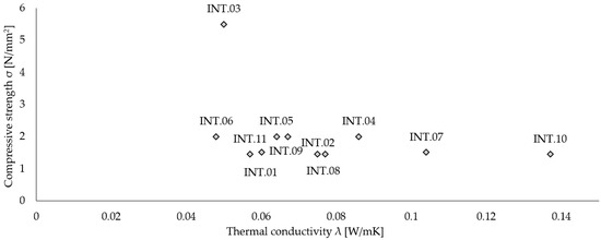
Figure 1.
Thermal plasters: σ–λ values of INT.01–INT.11.
2.2. Mechanical Characterization of the Constituent Materials
In the second phase of this work, an extensive experimental campaign was conducted to examine the constituent materials of the FRLM composite. In particular, the experimental campaign involved the following activities:
- Direct tensile test on the basalt fabric;
- Three-point bending and uniaxial compression tests on the selected insulating thermal plasters.
2.2.1. Mechanical Properties of Basalt Fabric
Basalt fabric is a balanced bi-axial mesh of 17 × 17 mm, with an equivalent thickness tf equal to 0.032 mm. The mesh comprises unique basalt fiber and stainless-steel micro-threads to guarantee stability and performance in both directions.
Specifically, four basalt fabric specimens consisting of one (BT.01), two (BT.02), three (BT.03), and four (BT.04) longitudinal multifilaments were tested under direct tension.
Direct uniaxial tensile tests were conducted on the basalt fabric to examine its mechanical properties. The tests were performed at room temperature, with controlled displacement, using a universal testing machine equipped with a 600 kN load cell. The load was applied with a rate of 0.25 mm/min. The tests were conducted according to the ASTM standard [7].
Global displacements were acquired by an axial clip-on extensometer, integrated into the universal testing machine [28], and installed on half of each fabric specimen (Figure 2).
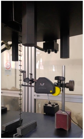
Figure 2.
Direct tensile test on the BT.01 basalt fabric specimen.
The maximum tensile strength fb was obtained as follows:
where Fmax is the maximum load value, Af = n ·; w · t represents the equivalent cross-sectional area of the fabric, n is the number of longitudinal fiber bundles of the specimen, w = 17 mm is the pitch between the bundles of fibers, and tf = 0.0032 mm is the equivalent thickness.
fb = Fmax/Af
The corresponding maximum strain εb was evaluated as the ratio between the maximum value of displacement δmax and the free length of the samples lf = 385 mm:
εb = δmax/lf
Figure 3 shows the tensile stress–strain behavior of the basalt fibers: all the curves are similar in shape, suddenly dropping after reaching the peak stress value.
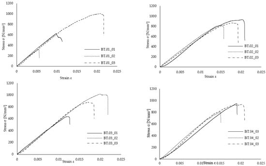
Figure 3.
Stress–Strain curves of the four basalt fabric specimens consisting of one (BT.01), two (BT.02), three (BT.03), and four (BT.04) longitudinal multifilaments.
Young’s tensile modulus was evaluated at the stress–strain curve’s first (approximately) linear branch. The average values of the maximum load Fmax, tensile strength fb, Young’s modulus Eb, and ultimate strain εb are reported in Table 2.
Table 2.
Mechanical properties of basalt fabric.
2.2.2. Mechanical Properties of the Insulating Thermal Plasters
Once the basalt fabric was tested, three specimens 40 × 40 × 160 mm3 in size for each type of thermal mortar (INT.01–INT.11) were prepared using special standardized metal molds. According to the product’s technical datasheets, the insulating thermal plaster specimens were prepared using a water amount of approximately 70% by weight.
According to UNI EN 1015-1 [29], after curing for 28 days in a controlled temperature room, the thermal mortars were tested under three-point bending tests (Figure 4a). Then, axial compression tests on the two stumps obtained after the failure of each specimen due to the bending tests were performed (Figure 4b).
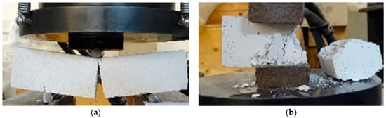
Figure 4.
(a) Three-point bending test on a mortar prism; (b) Uniaxial compression test on a mortar prism.
Specifically, the experimental program included tests on three specimens of each thermal mortar, i.e., 33 three-point bending tests and 66 compression tests.
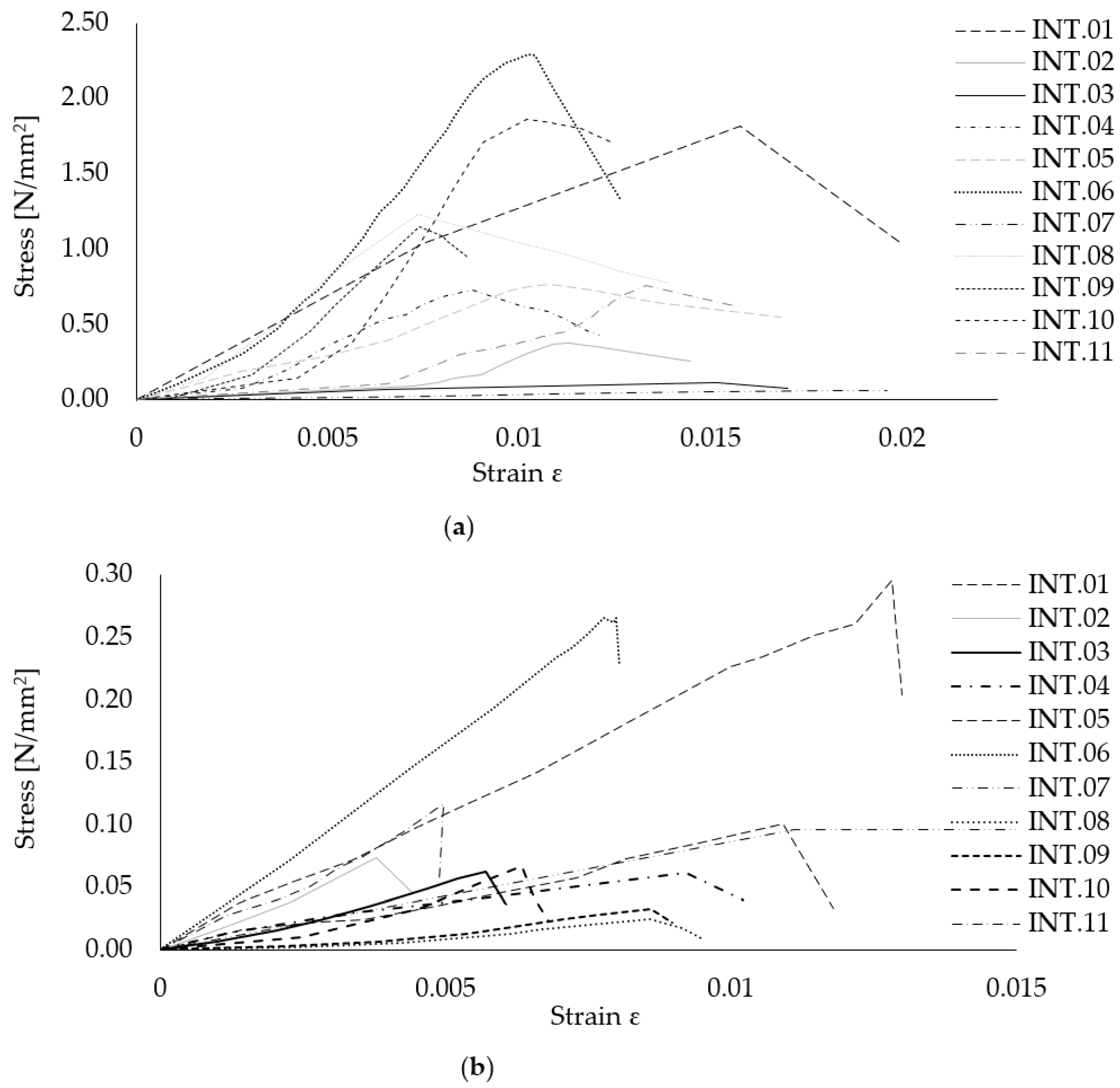
The tests were conducted under displacement control using a universal hydraulic machine with a 600 kN hydraulic actuator. The eleven thermal mortar specimens’ compressive and flexural stress–strain curves are plotted in Figure 5a,b.
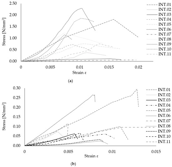
Figure 5.
(a) Compressive stress–strain curves of INT.01–INT.11; (b) Flexural stress–strain curves of INT.01–INT.11.
The results of the three-point bending tests and compression tests are summarized in Table 3 in terms of compressive strength (fc), compressive elastic modulus (Ec), and flexural strength (fb). The elastic modulus was calculated between 30% and 60% of the maximum load [30,31,32] at the stress–strain curve’s first (approximately) linear branch.
Table 3.
Mechanical properties of the INT.01–INT.11 matrices (experimental results).
It can be noted that the insulating thermal plasters INT.06 and INT.10 are characterized by the highest mean values of Young’s compressive modulus, equal to 292.51 N/mm2 and 385.09 N/mm2, respectively. However, INT.01 and INT.06 showed the highest mean values regarding compressive and flexural strength.
2.3. Evaluation of the Hygrothermal Performances of the Matrices
Following UNI EN 15026:2008 [33], numerical hydrothermal simulations were carried out to determine the hygrothermal performance of building components under real climate conditions to achieve dynamic equilibrium between the walls and the surrounding environment.
The purpose was to explore the transient hygrothermal behavior of multi-layer building components, incorporating the abovementioned products in a one-dimensional approach.
This study examined the hydrothermal behavior of different scenarios by analyzing all eleven selected products when applied to different masonry typologies. The reason for doing this was to investigate the impact of the various insulating thermal plasters on the hydrothermal behavior of the structures while also replacing the traditional plaster.
The analysis used Florence city’s climatic reference conditions over ten years.
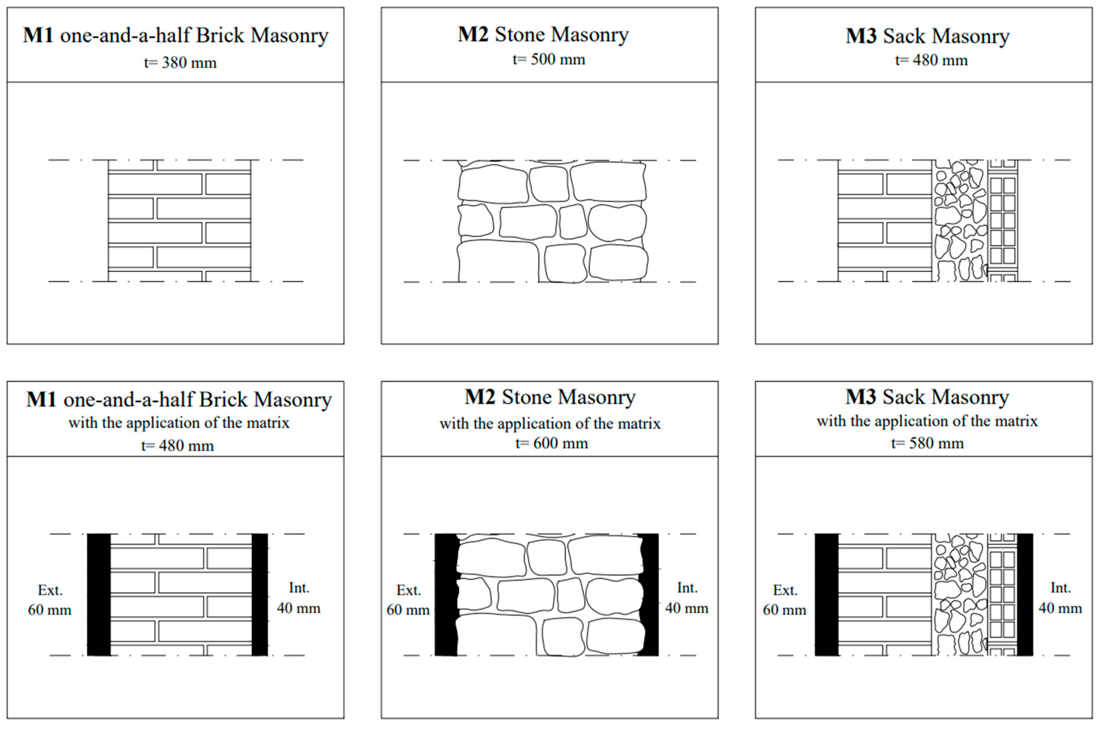
For the simulation, three distinct technical solutions for the masonry buildings most frequented in Florence were examined in the realm of the preservation of masonry structures (Figure 6). These solutions were selected from the list supplied by UNI/TR 11552 [34]:
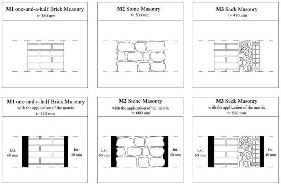
Figure 6.
Stratigraphy of the building components with and without the application of insulating thermal plasters.
- M1 one-and-a-half brick masonry with a total thickness of 380 mm;
- M2 stone masonry, with a total thickness of 500 mm;
- M3 sack masonry, with a total thickness of 480 mm.
At this stage, with the aim of seismic and energy upgrades, it was assumed that each thermal-insulating plaster (from INT.01 to INT.11) would be applied on both sides of the wall, with a thickness of 60 mm on the exterior layer and 40 mm on the interior layer.
Since it is significant to monitor the water content and humidity levels inside building components because the presence of water can alter their properties, leading to a gradual deterioration of the materials as well as the occurrence of mold and condensation on the walls, the water inside the wall (kg/m3) was analyzed, specifically on the side most exposed to heavy rain and prevailing winds. The variations in water content inside the wall for all the examined solutions depend only on seasonal changes.
The simulations indicate that the water content progressively increases in all the analyzed solutions over ten years. Initially, the structure has yet to attain a dynamic equilibrium with the surrounding environment. However, once this equilibrium is achieved, the water content in the wall exhibits variations corresponding to seasonal changes.
Moreover, the analysis reveals that the wall components, specifically INT.06, INT.01, and INT.05, demonstrate a higher capability to allow the passage of humid air. These components also exhibit a lower percentage of water content within the wall, reaching maximum values of 10–11 kg/m3.
The water content in the insulating thermal plaster layers on the interior side was also examined to prevent interstitial condensation.
Among all the solutions analyzed, product INT.03 exhibits the lowest annual average values for water content, ranging from a minimum of 3.0 kg/m3 to a maximum of 5.30 kg/m3. In contrast, the thermal plaster INT.01, which is cork-based, demonstrates the highest values, reaching a maximum water content of nearly 11.56 kg/m3 during the cold season and an average annual value of 7.70 kg/m3. The products INT.06 and INT.05 display a mean value of 4.40 kg/m3 with a maximum of 6.60 kg/m3, while the products INT.11 and INT.02 exhibit a similar behavior, with a mean value of 6.57 kg/m3 and a maximum of 8.10 kg/m3.
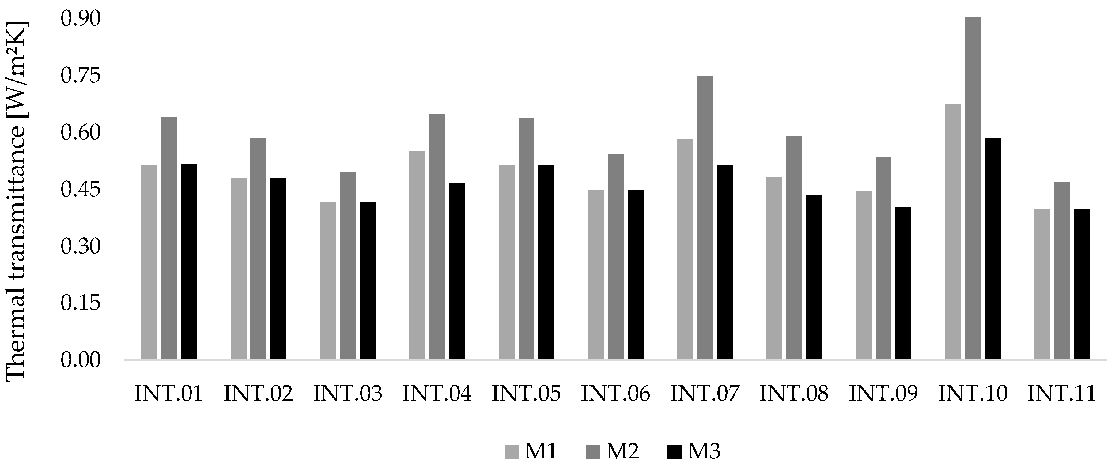
In Figure 7, the thermal transmittance values (W/m2K) are presented for the different solutions M1, M2, and M3 as they apply to the climate of Florence. The thermal transmittance values of the three different scenarios are based on the hygrothermal simulation, calculated through the input data (material thickness and thermal conductivity in particular) of the whole analyzed components.
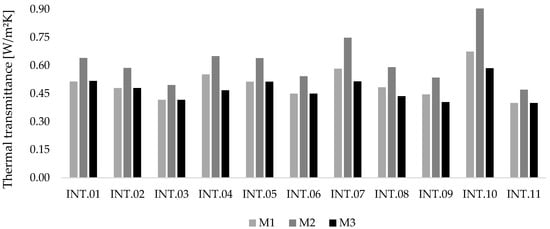
Figure 7.
Comparison of thermal transmittance values of the different configurations for the climate of Florence.
2.4. Dynamic Energy Building Simulation of Selected Insulating Thermal Plasters
According to the previous analysis, it is possible to notice how INT.01 and INT.06 represent the ideal configurations for mechanical performances and hygrothermal properties, characterized by a thermal conductivity λ equal to 0.060 W/mK and 0.048 W/mk, respectively (regarding the product’s datasheets). For this reason, those two products were selected for dynamic energy simulations at the building scale for the three wall typologies: M1 (one-and-a-half brick masonry), M2 (stone masonry), and M3 (sack masonry). Numerical dynamic energy simulations at the building scale were carried out to estimate the energy savings for the investigated solutions. The model consists of a single room in an outdoor laboratory that tests for the energy performance assessment of building facades, characterized by an insulated wooden envelope with opaque walls having a thermal transmittance of 0.29 W/m2K and a removable wall to test building envelope prototypes (Figure 8). The aim was to check the potential energy savings achievable considering the better mechanical and thermo-hygrometric properties of the best insulating thermal plasters when applied to the masonry walls.
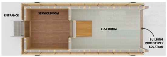
Figure 8.
Test cell: horizontal section.
The energy–building simulations were carried out for the typical winter and summer weeks with the application of each insulating thermal plaster to the testing masonry walls.
Table 4 lists the different scenarios evaluated by dynamic energy simulations. The purpose of the simulations was aimed at investigating the potential energy savings and the indoor comfort achievable during the whole year for the three wall typologies, M1, M2, and M3, by using INT.01 (Case 1) and INT.06 (Case 2) on both sides of the wall (a layer of 60 mm in thickness on the outer side and 40 mm on the inner side). The simulation results were compared to the data obtained from the “basic case” by applying a traditional plaster on both sides of the wall (a layer of 20 mm thickness on the outer side and 20 mm on the inner side).
Table 4.
Scenarios using dynamic energy simulations at the building scale for the selected thermal mortars.
In the following, the hydrothermal simulation hypothesis of the M1 scenario for the climate of Florence is reported as an example; the exposure of the testing walls was evaluated on the west orientation, considering heavy rain and prevailing winds.
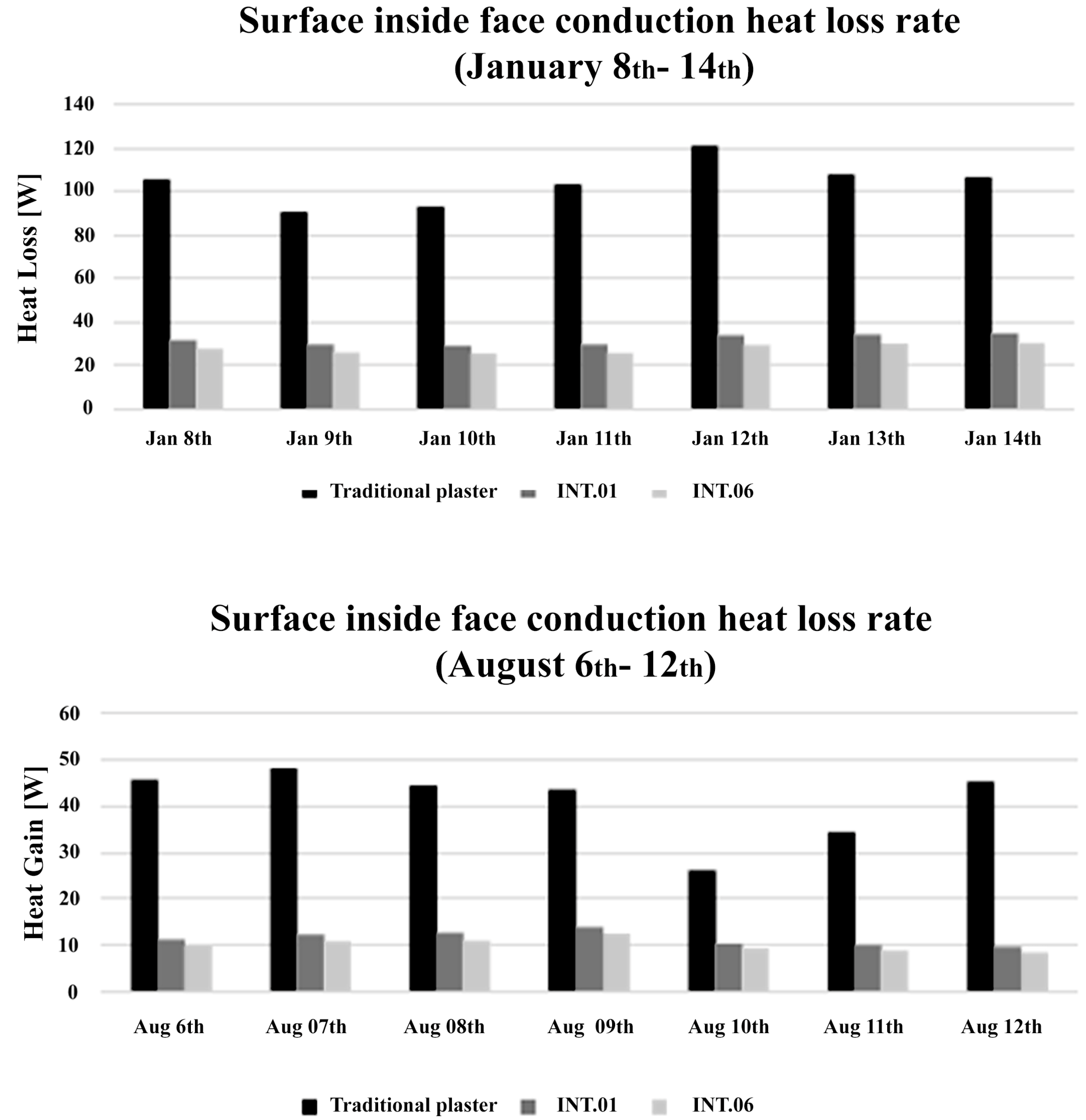
The results on the energy performance of scenario M1 show that there are no significant differences between the INT.01 and INT.06 plasters. In the winter season, the insulating performance of the test wall increases in both cases, reducing the annual heat losses through the envelope by up to 68% compared to the “basic case” with traditional plaster. In the summer season, the annual heat gains through the envelope decrease by up to 77% compared to the “basic case” (Figure 9).

Figure 9.
Surface inside face conduction heat loss rate and heat gain rate.
Comparing the three scenarios, the simulations showed different results regarding indoor comfort between the M1, M2, and M3 typologies. Increasing the thermal transmittance U of the wall, M1 was insufficient to improve indoor comfort during the year: the simulations performed during the coldest and hottest day of the year showed no significant changes in terms of the zone mean radiant temperature. However, considering M2 and M3, the zone mean radiant temperature values showed a better profile during the winter than the basic case with traditional plaster.
2.5. Mechanical Properties of the FRLM Composite Material
The basalt fabric type BT.04, the one characterized by the best tensile strength equal to 894.24 N/mm2, was embedded symmetrically in the thermal plaster labeled INT.06, i.e., the best mortar in terms of thermal and mechanical properties, characterized by a compressive strength equal to 2.49 N/mm2.
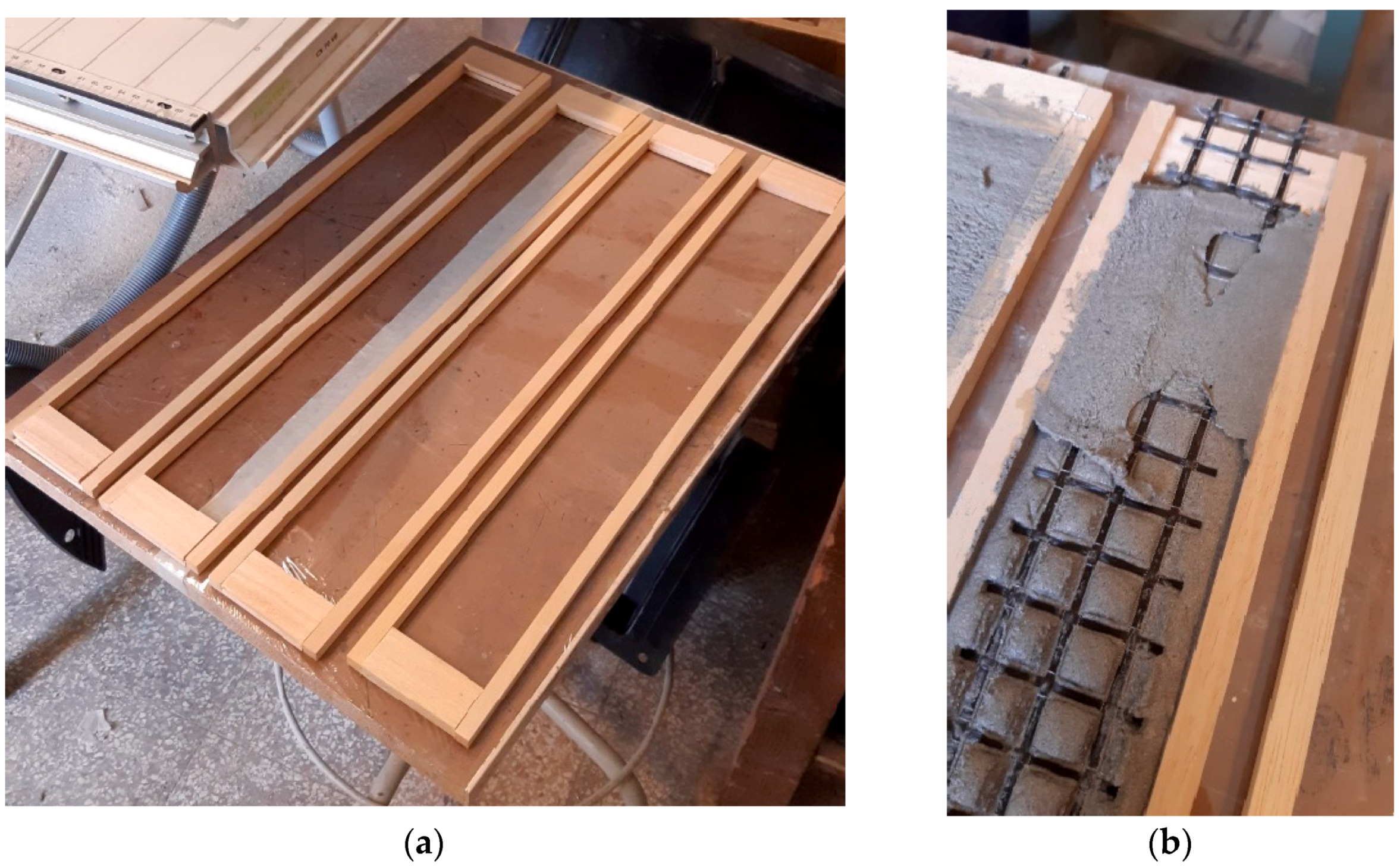
Three specimens labeled T-01, T-02, and T-03, 500 × 65 × 10 mm3 in size, after curing for 28 days at room temperature, were assembled: a first 5 mm thick layer of the mortar was applied on the base of the pre-prepared wood formworks, then the basalt fabric was pressed and placed on the top of the first layer, and finally, the second 5 mm thick layer was cast (Figure 10). Considering that the determination of layer thickness in testing is a critical parameter that can significanlty impact the characteristics of the material under investigation, unlike the thermal analysis, the thickness for the direct tensile test samples was a standardized layer of 10 mm [14].

Figure 10.
(a) Preparation of the casting; (b) Preparation of the FRLM coupons.
Two bolted steel plates controlled by a torque wrench were used on each end of the composite coupons (Figure 11). Additional aluminum layers were used at the end of the FRLM specimens to prevent friction between the samples and the bolted steel plates. For each specimen, the local displacements were captured using two proper cantilever-type displacement transducers vertically positioned on two aluminum L profiles, respectively located at the top edge of the bottom bolted steel plates (displacement transducers 1) and the bottom edge of the top bolted steel plates (displacement transducers 2) both indicated in the red triangles in Figure 12. The tests were performed under displacement control, with a 0.2 mm/min rate, using a universal machine with a 600 kN load cell (Figure 12).
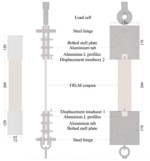
Figure 11.
FRLM test set up (dimension in mm, red triangles indicate the position of the displacements transducers 1 and 2).
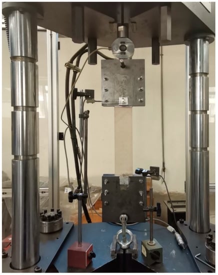
Figure 12.
Direct tensile test on the FRLM coupon T-01.
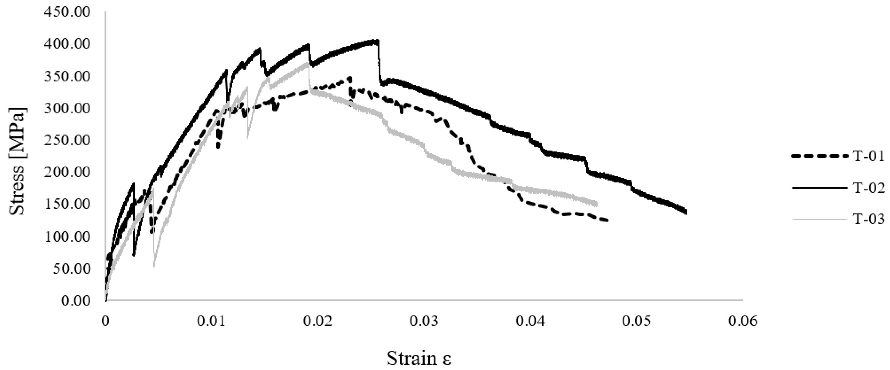
Direct tensile testing was performed on three specimens following the ASTM D3039/D3039M-17 [7] standard to provide the constitutive law of the composite.
As is visible in Figure 13, the tested specimens showed similar mechanical behaviors, characterized by three stages. Mainly, the formation of the first crack in the matrix occurred at a stress equal to 170 N/mm2 and a strain equal to 0.004: this caused a sudden reduction of the load-carrying capability.

Figure 13.
Tensile stress–strain curves of the FRLM composite material.
Meanwhile, the stressing branch did not highlight a variation in its slope. A second crack in the composite specimen occurred when the tension reached a value between 300 and 370 N/mm2, while the strain was in the percentage range equal to 0.012 and 0.015. Then, cracks increased due to the beginning of sliding phenomena between the fabric and the surrounding matrix. A basalt fabric multifilament failed when the peak stress was reached (with a value ranging between 320 and 420 N/mm2).
The ultimate strain was in a percentage range between 0.045 and 0.055. The results of the FRLM specimens regarding mechanical properties are summarized in Table 5, where the specimen types are listed in the first column. The maximum load Ftmax, the tensile strength ft, the Young’s modulus Et, and the maximum deformation εt are reported.
Table 5.
Mechanical properties of FRLM coupons.
Finally, the increase of the existing cracks characterized the post-peak softening branch, the formation of new cracks, and increased strain with a soft decrease of the applied tensile load.
3. Results and Discussion
To design an innovative eco-friendly FRLM composite material, this research analysis integrated seismic and energy requalification strategies necessary for retrofitting the masonry building heritage.
This paper is divided into four sections. The Section 1 focused on identifying natural inorganic insulating thermal plasters to be used as matrices of the composite material.
Once the insulating thermal plasters with potential mechanical and energy properties were selected, a mechanical characterization of the component materials of the FRLM composite involved three-point bending and uniaxial compression tests on the selected insulating thermal mortars and direct tensile tests on the basalt fabrics. INT.01 and INT.06 demonstrate the highest average values concerning compressive strength (2.41 N/mm2 and 2.49 N/mm2, respectively) and flexural strength (0.30 N/mm2 and 0.27 N/mm2, respectively).
According to the direct tensile tests on the basalt fabrics, type BT.04 is characterized as the best with a tensile strength equal to 894.24 N/mm2. For this reason, it was chosen to reinforce the FRLM composite material.
The third phase of this research involved the analysis of the hydrothermal properties using dynamic simulations carried out with software for evaluating moisture conditions in building envelopes. The simulations showed that the moisture content consistently rises over ten years in all the examined options. Once this balance is reached, the moisture content in the wall exhibits variations corresponding to seasonal variations. As a result, only INT.01, INT.05, and INT.06 demonstrated high hygrometric performances with a low quantity of water collected within the wall structure, exhibiting a lower percentage of water content within the wall, reaching maximum values of 10–11 kg/m3.
Energy building simulations were then carried out on INT.01 and INT.06 to evaluate the energy savings at the building scale. The individual walls’ energy performance results indicate no notable distinctions between INT.01 and INT.06.
Finally, direct tensile testing was performed on the FRLM comprising INT.06, the best insulating thermal plaster in terms of thermohydrometric and mechanical properties, reinforced with the basalt fabric type BT.04. Specifically, the analyzed mechanical properties of the new FRLM composite material are the average maximum load Ftmax, equal to 779.39, the average tensile strength ft, equal to 374.72 N/mm2, the Young’s modulus Et equal to 16,954.08 N/mm2, and the maximum deformation εt, equal to 0.020.
4. Conclusions
This study aimed to analyze the thermal and mechanical properties of a new composite material of basalt fabric embedded in an inorganic matrix of natural hydraulic lime mixed with natural aggregates.
Through a preliminary theoretical analysis, it was found that the identification of thermal mortars that are compatible with the masonry substrate to be reinforced is a crucial step for the design of composite materials to be used for the energy and structural upgrading of historic buildings while complying with the principles of compatibility, sustainability, and reversibility [35].
Once the ideal products with desirable mechanical and energy properties were identified from the available products in the national and international markets, the next step involved conducting three-point bending and compression tests to characterize the thermal mortars.
According to the experimental results, the mortars INT.01 and INT.06 showed the best mechanical properties regarding compressive strength. Specifically, the INT.06 mortar had the highest compressive strength, measuring at 2.49 N/mm2 and with a Young’s modulus of 319.86 N/mm2.
According to the hydrothermal simulations, the INT.01 and INT.06 mortars showed the best performance in terms of vapor permeability. Using INT.01 and INT.06 mortars increased the wall’s vapor permeability, which reduced water content and minimized the risk of moisture-related damage: this helps maintain the masonry’s structural integrity and improves microclimatic conditions, meaning that the use of the INT.06 mortar in the composite material improved the energy efficiency of the walls, reducing heat loss and lowering energy consumption for heating. Based on the results reported in this research, it can be highlighted that the INT.01 and INT.06 thermal mortars demonstrate good mechanical and thermal properties.
The experimental findings show that the INT.06 thermal mortar is considered the most appropriate matrix for the innovative FRLM composite, meeting both mechanical and thermal criteria.
The direct tensile test conducted on the FRLM composite material, consisting of the INT.06 matrix embedded basalt fabric, indicated that the FRLM composite specimens achieved an average maximum tensile strength value of 374.72 N/mm2, with a Young’s modulus of 16,954.08 N/mm2, showing that the FRLM composite material has excellent tensile performance.
By virtue of the above-reported results, the novel FRLM composite can be considered a promising material for additional research investigations and future applications in engineering practice. More in-depth experimental campaigns and numerical simulations, following an integrated thermo-mechanical approach, are needed to validate these data against different masonry substrates.
Author Contributions
All authors performed investigation and participated to the writing and the final review. All authors have read and agreed to the published version of the manuscript.
Funding
The financial support of the Italian Ministry of University and Research (MUR) through the PRIN2022 project ‘Unified approach for improving structural and thermal response of masonry buildings with optimized sustainable composite materials—ASThRO-Co’ is gratefully acknowledged.
Data Availability Statement
The data presented in this study are available in Ref. [27].
Conflicts of Interest
The authors declare no conflict of interest.
References
- de Falco, A.; Giresini, L.; Sassu, M. Temporary preventive seismic reinforcements on historic churches: Numerical modeling of san frediano in pisa. Appl. Mech. Mater. 2013, 351, 1393–1396. [Google Scholar] [CrossRef]
- Alecci, V.; Ayala, A.G.; De Stefano, M.; Marra, A.M.; Nudo, R.; Stipo, G. Influence of the masonry wall thickness on the outcomes of double flat-jack test: Experimental and numerical investigation. Constr. Build. Mater. 2021, 285, 122912. [Google Scholar] [CrossRef]
- Karantoni, F.V.; Lyrantzaki, F.; Fardis, M.N.; Karantoni, F.; Lyrantzaki, F.; Tsionis, G. Seismic Fragility Functions of Stone Masonry Buildings. In Proceedings of the 15th World Conference on Earthquake Engineering, Lisbon, Portugal, 24–28 September 2012; Available online: https://www.researchgate.net/publication/284448129 (accessed on 13 April 2021).
- Litti, G.; Khoshdel, S.; Audenaert, A.; Braet, J. Hygrothermal performance evaluation of traditional brick masonry in historic buildings. Energy Build. 2015, 105, 393–411. [Google Scholar] [CrossRef]
- Pohoryles, D.A.; Bournas, D.A.; Da Porto, F.; Caprino, A.; Santarsiero, G.; Triantafillou, T. Integrated seismic and energy retrofitting of existing buildings: A state-of-the-art review. J. Build. Eng. 2022, 61, 105274. [Google Scholar] [CrossRef]
- Mistretta, F.; Stochino, F.; Sassu, M. Structural and thermal retrofitting of masonry walls: An integrated cost-analysis approach for the Italian context. Build. Environ. 2019, 155, 127–136. [Google Scholar] [CrossRef]
- ASTM D3039/D3039M; Standard Test Method for Tensile Properties of Polymer Matrix Composite Materials 1. 2017. Available online: compass.astm.org (accessed on 20 July 2021).
- Bournas, D.A. Concurrent seismic and energy retrofitting of RC and masonry building envelopes using inorganic textile-based composites combined with insulation materials: A new concept. Compos. B Eng. 2018, 148, 166–179. [Google Scholar] [CrossRef]
- In-lb. Guide to Design and Construction of Externally Bonded Fabric-Reinforced Cementitious Matrix (FRCM) and Steel-Reinforced Grout (SRG) Systems for Repair and Strengthening Masonry Structures Inch-Pound Units. 2020. Available online: www.concrete.org (accessed on 26 July 2023).
- Donnini, J.; De Caso y Basalo, F.; Corinaldesi, V.; Lancioni, G.; Nanni, A. Fabric-reinforced cementitious matrix behavior at high-temperature: Experimental and numerical results. Compos. B Eng. 2017, 108, 108–121. [Google Scholar] [CrossRef]
- Al-Lami, K.; D’Antino, T.; Colombi, P. Study of the Bond Capacity of FRCM- and SRG-Masonry Joints. CivilEng 2021, 2, 68–86. [Google Scholar] [CrossRef]
- Donnini, J.; Spagnuolo, S.; Corinaldesi, V. A comparison between the use of FRP, FRCM and HPM for concrete confinement. Compos. B Eng. 2019, 160, 586–594. [Google Scholar] [CrossRef]
- ICOMOS. Principles for the Preservation and Conservation/Restoration of Wall Paintings Icomos Principles for the Preservation and Conservation/Restoration of Wall Paintings Introduction and Definition. 2003. Available online: www.icomos.org (accessed on 4 August 2023).
- CNR-DT 215/2018; Advisory Committee on Technical Recommendations for Construction. National Research Council Advisory Committee on Technical Recommendations for Construction Guide for the Design and Construction of Externally Bonded Fibre Reinforced Inorganic Matrix Systems for Strengthening Existing Structures. 2020. Available online: www.cnr.it/en (accessed on 20 July 2021).
- Sneed, L.H.; D’Antino, T.; Carloni, C.; Pellegrino, C. A comparison of the bond behavior of PBO-FRCM composites determined by double-lap and single-lap shear tests. Cem. Concr. Compos. 2015, 64, 37–48. [Google Scholar] [CrossRef]
- D’Ambrisi, A.; Feo, L.; Focacci, F. Experimental and analytical investigation on bond between Carbon-FRCM materials and masonry. Compos. B Eng. 2013, 46, 15–20. [Google Scholar] [CrossRef]
- Zhang, H.; Huang, Y.J.; Yang, Z.J.; Xu, S.L.; Chen, X.W. A discrete-continuum coupled finite element modelling approach for fibre reinforced concrete. Cem. Concr. Res. 2018, 106, 130–143. [Google Scholar] [CrossRef]
- D’Antino, T.; Carloni, C.; Sneed, L.H.; Pellegrino, C. Matrix-fiber bond behavior in PBO FRCM composites: A fracture mechanics approach. Eng. Fract. Mech. 2014, 117, 94–111. [Google Scholar] [CrossRef]
- Alecci, V.; De Stefano, M.; Galassi, S.; Luciano, R.; Pugliese, D.; Stipo, G. Influence of Different Mortar Matrices on the Effectiveness of FRCM Composites for Confining Masonry Columns. J. Test. Eval. 2022, 51, 735–750. [Google Scholar] [CrossRef]
- Carbonaro, C.; Tedesco, S.; Thiebat, F.; Fantucci, S.; Serra, V.; Dutto, M. Development of vegetal based thermal plasters with low environmental impact: Optimization process through an integrated approach. Energy Procedia 2015, 78, 967–972. [Google Scholar] [CrossRef]
- Fořt, J.; Čáchová, M.; Vejmelková, E.; Černý, R. Mechanical and hygric properties of lime plasters modified by biomass fly ash. In IOP Conference Series: Materials Science and Engineering; Institute of Physics Publishing: Bristol, UK, 2018. [Google Scholar] [CrossRef]
- Yang, E.-H.; Yang, Y. Use of High Volumes of Fly Ash to Improve ECC Mechanical Properties and Material Greenness. ACI Mater. J. 2007, 104, 620. [Google Scholar]
- Triantafillou, T.C.; Karlos, K.; Kefalou, K.; Argyropoulou, E. An innovative structural and energy retrofitting system for URM walls using textile reinforced mortars combined with thermal insulation: Mechanical and fire behavior. Constr. Build. Mater. 2017, 133, 1–13. [Google Scholar] [CrossRef]
- Napolano, L.; Menna, C.; Asprone, D.; Prota, A.; Manfredi, G. LCA-based study on structural retrofit options for masonry buildings. Int. J. Life Cycle Assess. 2015, 20, 23–35. [Google Scholar] [CrossRef]
- Monaco, M.; Aurilio, M.; Tafuro, A.; Guadagnuolo, M. Sustainable mortars for application in the cultural heritage field. Materials 2021, 14, 598. [Google Scholar] [CrossRef]
- UNI EN 998-1:2016; Specification for Mortar for Masonry—Part 1: Rendering and Plastering Mortar. 2016. Available online: store.uni.com/en/ (accessed on 20 July 2021).
- Alecci, V.; De Stefano, M.; Marra, A.M.; Pittau, F.; Pugliese, D.; Romano, R.; Stipo, G. A New Compatible and Sustainable FRLM Composite for the Seismic and Energetic Upgrade of Historic Buildings. In Proceedings of the NMP 2022: New Metropolitan Perspectives, Reggio Calabria, Italy, 24–26 May 2022; Lecture Notes in Networks and Systems. Springer Science and Business Media: Cham, Switzerland, 2022; pp. 2223–2232. [Google Scholar] [CrossRef]
- ASTM E83-23; Standard Practice for Verification and Classification of Extensometer Systems 1. 2023. Available online: compass.astm.org (accessed on 4 August 2023).
- UNI EN 1015-11:2019; Methods of Test for Mortar for Masonry—Part 11: Determination of Flexural and Compressive Strength of Hardened Mortar. 2019. Available online: store.uni.com/en/ (accessed on 25 August 2022).
- Gucci, N.; Barsotti, R. A non-destructive technique for the determination of mortar load capacity in situ. Mater. Struct. 1995, 28, 276–283. [Google Scholar] [CrossRef]
- Simões, A.; Simões, S.; Bento, R.; Gago, A.; Lopes, M. Mechanical Characterization of Masonry Walls with Flat-Jack Tests. Exp. Tech. 2016, 40, 1163–1178. [Google Scholar] [CrossRef]
- Valluzzi, M.R.; Binda, L.; Modena, C. Mechanical behaviour of historic masonry structures strengthened by bed joints structural repointing. Constr. Build. Mater. 2005, 19, 63–73. [Google Scholar] [CrossRef]
- UNI EN 15026:2008; Hygrothermal Performance of Building Components and Building Elements—Assessment of Moisture Transfer by Numerical Simulation. 2008. Available online: store.uni.com/en/ (accessed on 25 August 2022).
- UNI/TR 11552:2014; Opaque Envelope Components of Buildings—Thermo-Physical Parameters. 2014. Available online: store.uni.com/en/ (accessed on 25 August 2022).
- Romano, R.; Alecci, V.; Donato, A.; Palumbo, E.; Pisciotta, C.; Pugliese, D.; Marra, A.M.; Stipo, G. Innovative and Eco-Compatible Materials for the Regeneration of the Historical Buildings Located in the Med. In Proceedings of the CEES 2021-International Conference on Construction, Energy, Environment and Sustainability, Coimbra, Portugal, 12–15 October 2021; Available online: https://www.sba.unifi.it/upload/policy-oa-2016-1.pdf (accessed on 25 August 2022).


Disclaimer/Publisher’s Note: The statements, opinions and data contained in all publications are solely those of the individual author(s) and contributor(s) and not of MDPI and/or the editor(s). MDPI and/or the editor(s) disclaim responsibility for any injury to people or property resulting from any ideas, methods, instructions or products referred to in the content. |
© 2023 by the authors. Licensee MDPI, Basel, Switzerland. This article is an open access article distributed under the terms and conditions of the Creative Commons Attribution (CC BY) license (https://creativecommons.org/licenses/by/4.0/).