Abstract
In the present study, the mechanical behavior of Fiber-Reinforced Concrete (FRC) beams was studied under bending until rupture. Each beam was reinforced with a hybrid mix of short fibers randomly distributed in its volume. Concrete beams with three different fiber combinations were investigated, namely, beams reinforced with (1) a homogeneously distributed mix of short polypropylene fibers (PP) and steel fibers, (2) PP fibers and Alkali Resistant Glass (ARG) fibers, and (3) PP and composite fibers (CF). The amount of short PP fibers was the same in all FRCs. The investigation focused on the fracture mechanisms and the load-bearing capacity of FRC beams with the developing macro cracks. In total, 12 FRC composite prismatic specimens were casted and tested in four-point bending experiments (4PBT). The current load value versus the Crack Mouth Opening Displacement (CMOD) for all FRCs was analyzed. The crack opening relationship and the influence of fibers on the fracture energy and flexural tensile strength were determined. Rupture surfaces of all samples were investigated using an optical microscope.
1. Introduction
Concrete is one of the most frequently used building materials in construction throughout the world; it can be easily moulded into any desired durable structural shape. Reinforcement makes concrete stronger with regard to tension and shear; it also helps improve mechanical properties of the reinforced concrete as compared to the plain concrete [1,2,3,4]. Continuous reinforcement added to concrete increases its strength and ductility, but careful reinforcement placement requires full or partial use of manual labour. Nowadays, reinforced concrete is changing; steel in the reinforcing rebars is replaced by various other materials [5,6,7,8,9]. In many situations, rebars are replaced with short fibers added to the concrete mix [10,11,12,13].
It has been proven that the use of fibers in the plain concrete allows controlling shrinkage cracking and improves tensile properties of the material [14,15,16,17,18]. In many situations, introduction of short fibers in the plain or reinforced concrete may offer a better solution, since FRC may carry significant stresses over a relatively large strain region in the post-cracking stage (the stage of visual crack formation and growing). Short fibers may be used as the main or the secondary reinforcement (in combination with rebars), bearing the bending moments and the shear stresses. Several papers reported on the research into the properties of the concrete matrix successfully reinforced with various fibers made of various materials [19,20,21,22,23] and using different methods [24,25,26]. Fibers can be easily introduced into the concrete during ingredient mixing. After filling a mould and maturing of the concrete matrix, fibers act as a reinforcement, increasing the load-bearing capacity of the FRC. Fibers bridge the cracks, thus reducing and mitigating the crack propagation and damage effect [27]. In recent years, investigations in the field of composite materials have contributed greatly to the improvement of materials’ manufacturing technology, reducing costs and allowing widening their application areas. At the same time, only limited information about novel composite reinforcement for concrete is available, although the effectiveness of such reinforcement has been proven experimentally [28].
The main purpose of the paper is to show non-metallic (glass) and composite fibers potential comparing with well-known and traditionally used metal fibers. Geometry and mechanical behaviour of such fibers may have some peculiarities. The current research presents a study of fiber-reinforced concretes with three different mixtures of two types of fibers with a total volume fraction equal to 1.1%. Concrete with 12-mm polypropylene fibers (0.1%) and 26-mm steel fibers (1%). Concrete with 12-mm polypropylene fibers (0.1%) and 24-mm Alkali Resistant Glass fibers (1%), and finally concrete with 12-mm polypropylene fibers (0.1%) and 24-mm composite fibers (1%). The amount of short, 12-mm polypropylene fibers in all fiber-reinforced concretes was constant. Such hybrid fibers mixes were dispersed in the concrete volume during concrete fabrication.
2. Materials
Fibers
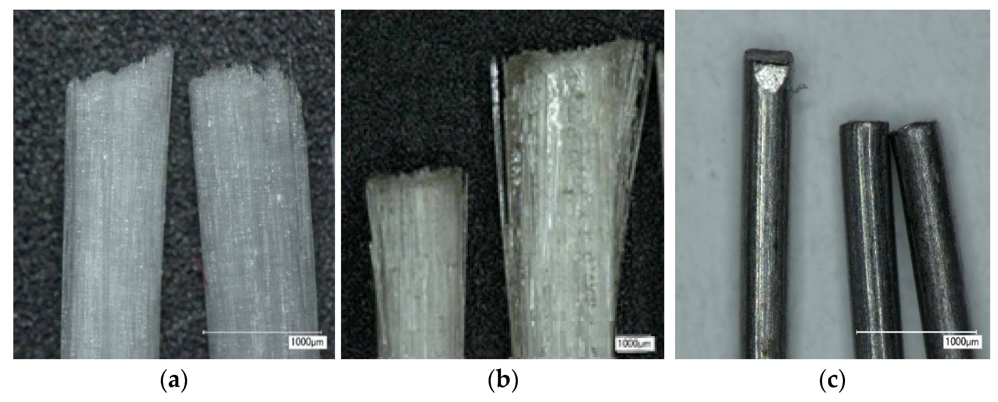
Four types of fibers were considered in the present research: steel fibers, ARG fibers, composite fibers, and polymer fibers (see Table 1 and Figure 1a–c).

Table 1.
Properties of fibers according to suppliers’ data sheets.
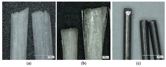
Figure 1.
(a) ARG fibers; (b) Composite fibers; (c) Steel fibers.
3. Preparation of Samples with the Hybrid Mix of Fibers
3.1. Mixing Concrete with Fibers
The composition of the concrete mix was the same for all three groups of samples. At the initial stage, all ingredients of the concrete mix were mixed together. Then, polymer fibers were added to the concrete and, after a few minutes of mixing, the main fibers were added (glass, composite or steel).
The mixing process in the experiment was as follows: Coarse, fine aggregates and cement (all ingredients) were added to a forced mixer and mixed for 3 min. Then, water with a plasticizer was slowly and evenly added to the mixer and mixing was continued for 7 min, after which the polypropylene fibers were added and mixing was continued for another 3 min, after which the main fibers were added (as planned, see Table 1) and mixing was continued for next 8 min.
As a result, fibers were distributed (mixing) uniformly throughout the concrete volume before pouring the FRC into the molds.
Sample sizes: The FRC was placed into the molds and, after maturing of the concrete, prismatic samples with the sizes of 100 × 100 × 400 mm were obtained. In total, 12 FRC composite prismatic specimens were casted, four in each group. The concrete beams reinforced with AR Glass (Vf = 1%) and polymer fibers (Vf = 0.1%) were designated as Group 1. Beams with composite (Vf = 1%) and polymer fibers (Vf = 0.1%) were designated as Group 2. Finally, concrete beams reinforced with steel (volume fraction Vf = 1%) and polymer (Vf = 0.1%) fibers were designated as Group 3. These groups were casted, placed for curing in water, and, after 28 days, were tested in 4PBT. The role of polypropylene fibers in all mixes was to arrest small cracks surrounding bigger cracks in the material. In addition, six samples of concrete without reinforcement were fabricated for testing. The samples with dimensions of 100 × 100 × 100 mm were prepared in order to determine compressive strength and the class of the concrete matrix under investigation.
3.2. Materials and Mix Proportions
Selecting raw materials for production of concrete, preference was given to locally available mineral materials and cement according to EN-206 [30]. Concrete mix proportions and properties of the ingredients are shown in Table 2. The proportions of the above-mentioned materials are given as per m3. The total number of fibers in one concrete prism 100 × 100 × 400 mm of the concrete mixes are shown in Table 3.

Table 2.
Composition of the designed concrete mix and components used.

Table 3.
Quantity of fibers.
Fly ash (Kozienice, Poland, supplied by Schwenk Latvia Ltd.) was used as a supplementary cementitious material and pozzolanic admixture. The applied fly ash with the cumulative content of oxides SiO2 + Al2O3 + Fe2O was equal to 84.7% thereof. It was classified as class F fly ash in accordance with ASTM C618 [31]. The basic properties of fly ash are given in Table 4.

Table 4.
Fly ash chemical composition and general properties, by supplier’s data.
4. Experimental Setup
4.1. Technological Properties’ Tests
Sieve Segregation Test
The test aims to investigate the resistance of High-Performance Concrete (HPC) to segregation [32] by measuring the portion of the fresh HPC sample passing through a 5-mm sieve. If the HPC has a poor resistance to segregation, the paste can easily pass through the sieve. Therefore, the sieved portion indicates whether the HPC is stable or not. This test was conducted for the reference concrete group (without fibers).
The sieved portion (the mass percentage of the sample passing through the sieve) was calculated using equation π presented below and expressed in percent to the nearest 1%. Π = ((Wps − Wp)/Wc) × 100
4.2. Structural Properties’ Tests
4.2.1. Compressive Strength (Concrete Cube Test)
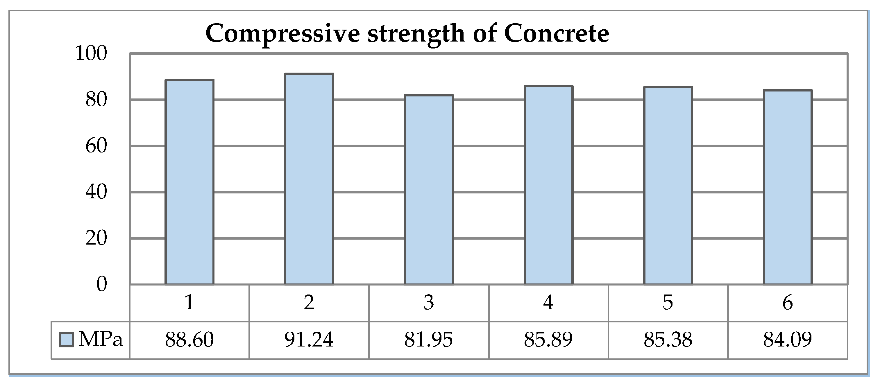
In the present research, the Materials Compressive Test was used in accordance with EN 12390-3 [33]. Standard compressive cube tests using 100 × 100 × 100-mm specimens were conducted to determine concrete compression strength after 28 days. The Compressive strength of six samples was found, as shown in Figure 2. According to standard LVS 156-1 [34], the correction factor 0.95 was implemented; thus, the obtained concrete corresponded to class C70/85.
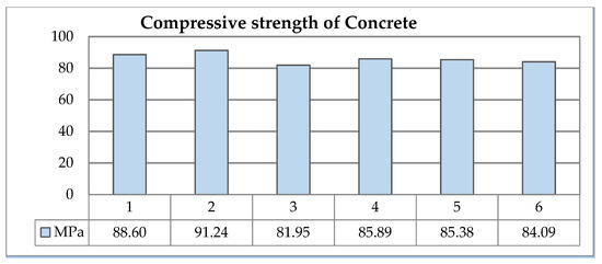
Figure 2.
Compressive strength of concrete at 28 days.
4.2.2. Four-Point Bending Test
Determination of the tensile strength using the direct tensile test for fiber-reinforced concretes is complicated due to big scatter of results and possible problems with their interpretation; therefore, the tensile strength was determined in the flexural experiments. The 4PBT is the most common test used for evaluating the mechanical and fracture properties of SFRC in the mode of crack propagation.
4.2.3. Testing Procedure
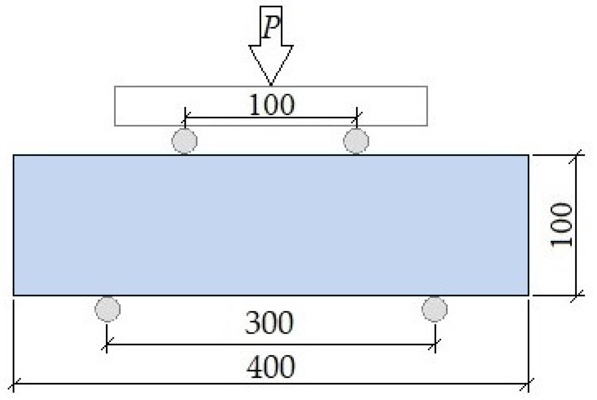
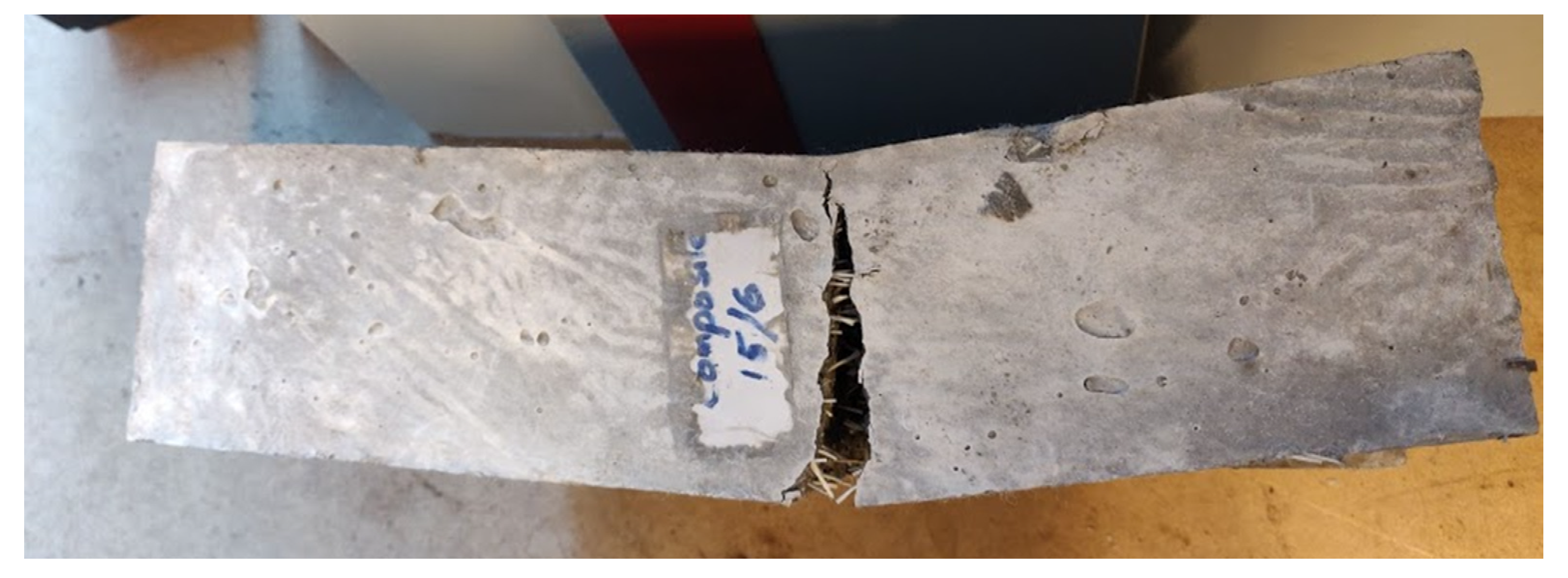
The 4PBT was performed after 28 days from the casting moment. The test with a constant bending moment in the middle part of the beam, applying loads through upper and lower rollers, was performed using a Controls Automax 5 4PBT testing machine, as shown in Figure 3. The FRC prisms were marked 50 mm from their ends. Each prism was inserted into a testing machine following these marks; the lower support points of the machine were placed on these marks, respectively. A frame with two Linear Displacement Transducers (LVDT) HBM WA10 on its sides was intended for recording the prism midpoint deflection during the test. The loading was applied monotonically in 0.25-kN steps for the period of 60 s in small increments, while the load and deflection were recorded at each increment. The maximum load was sustained, the deflection values were recorded, and the flexural strength was obtained. The measurement data from the strength measurements by using a Spider-8 data acquisition system were processed, synchronized, and saved. Deflection of the specimen was obtained by considering the values from both sensors and obtaining the average value. The graphs visualizing the processes in FRC, namely, behavior of the fibers under bending, were created. The test procedure was carried out for all three groups of samples in the same manner, as shown in Figure 3. An image of one tested sample is given in Figure 4. A Load was applied until the specimen broke completely.
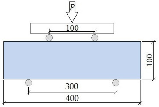
Figure 3.
The 4PBT scheme for testing of FRC beams.
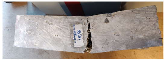
Figure 4.
Tested FRC sample.
5. Experimental Results and Discussion
5.1. Microscopic Analysis
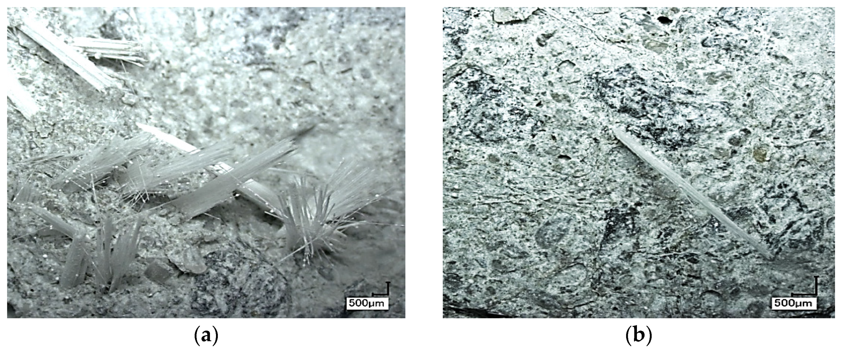
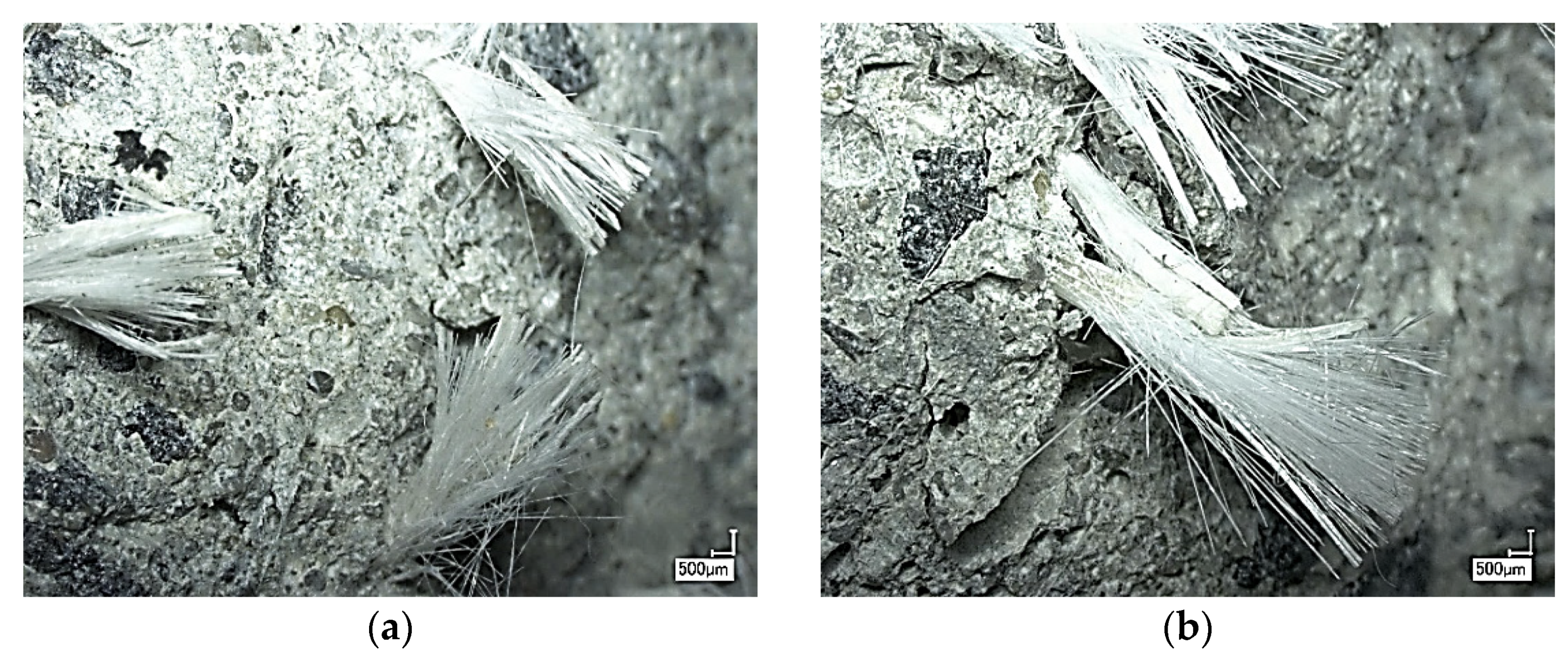
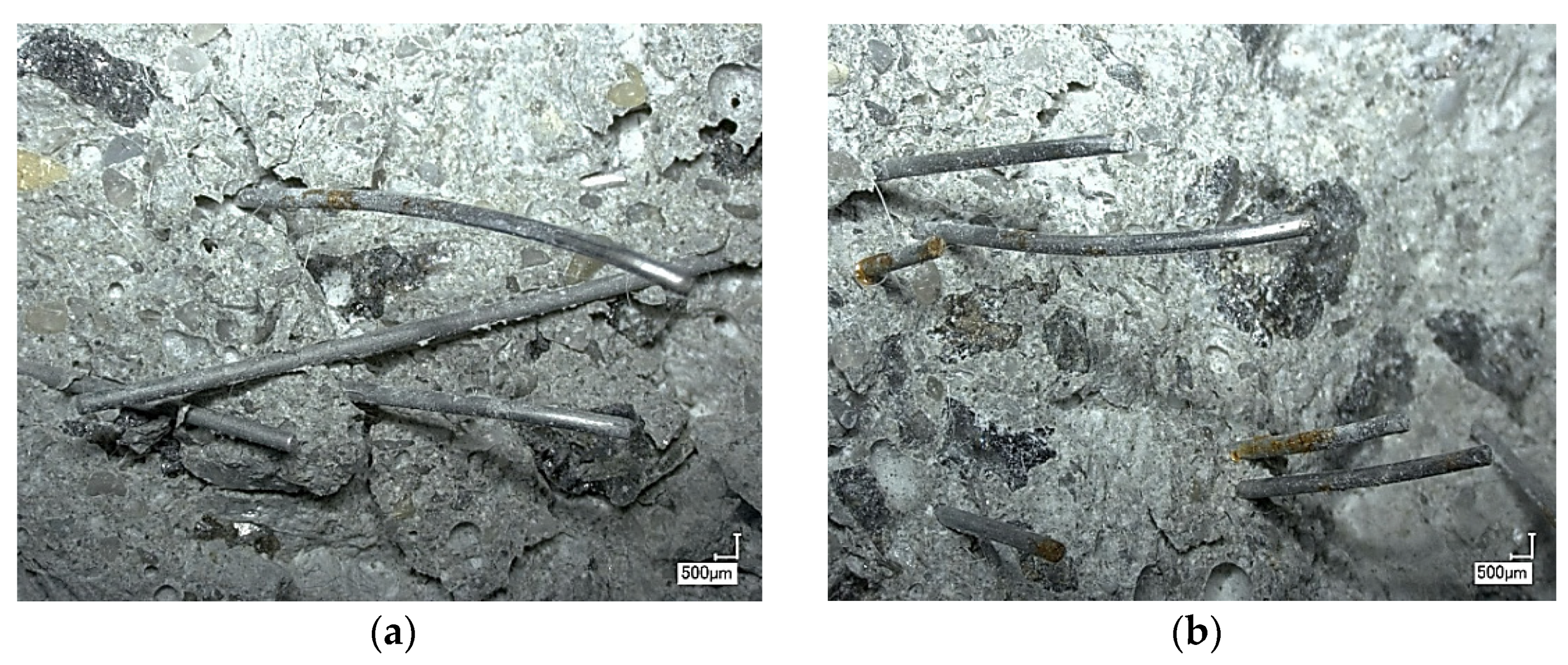
Upon completion of the testing, the samples were separated into two pieces at the fracture place; both sides of the rupture were investigated. Rupture surfaces were examined with the help of a high-resolution digital microscope Keyence WHX 2000. Rupture surfaces are shown in Figure 5a,b for concrete with ARG fibers, Figure 6a,b for concrete with CF fibers, and Figure 7a,b for concrete with SF fibers.
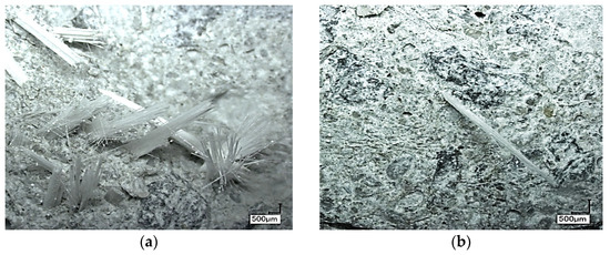
Figure 5.
(a,b) Microscopic view of the rupture surfaces for ARG and short PP fiber in the concrete matrix.
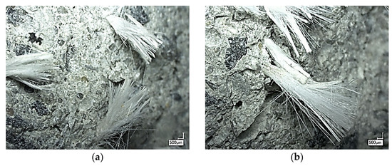
Figure 6.
(a,b) Microscopic view of the rupture surfaces for CF and short PP fiber in the concrete matrix.
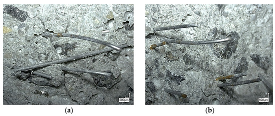
Figure 7.
(a,b) Microscopic view of the rupture surfaces for SF and short PP fiber in the concrete matrix.
Considering Figure 5a,b, it may be noticed that ARG fibers were characterized by the highest aspect ratio and the highest number of micro-fibers in a concrete volume unit (more than 3.3 × 10⁷ micro-fibers in one prism) between the analyzed variants. ARG are fabricated as catted monofilament fiber yarns (see Figure 5b). Each yarn consists of more than 1000 micro-fibers a few microns in diameter. Micro-fibers appeared in the yarns located close to each other. Figure 5a shows that simple mixing of ARG fiber threads did not lead to the separation of single fibers from the bundle. The concrete mix penetrated only the outer part of every ARG fiber yarn: It did not penetrate the inner part of each bundle. Fibers that were not surrounded by FRC only partially participated in the loadbearing process. Despite the presence of a large number of fibers (see Table 3), only part of them are participating in crack bridging. The Situation was much worse: The empty internal part of each ARG fiber yarn, its core, acted as a small crack in the concrete. The pulled-out core-fibers in the middle part of the yarn, where fibers are not surrounded by a concrete matrix, may be seen in Figure 5b.
FRC with PP and ARG fibers demonstrated the potential to carry higher applied loads if more glass micro-fibers were separated from the yarns (bundles), forming glass macro-fibers. This process was not easy to realize. If the mixing time of the fiber-reinforced concrete is increased rapidly, the amount of damaged micro-fibers in the mix will also increase.
Concrete did not penetrate each bundle fully: Only the fibers in the outer layer of the bundle were surrounded by concrete. During the loading, fibers broke and their short tails pulled out. Each glass fiber had a large aspect ratio; the fiber with high aspect ratio was not able to pull out and, thus, broke. Figure 6 presents a rupture surface of the concrete reinforced by PP and short CF fibers. CF fibers behaved like glass fibers, but with a smaller friction. During macro-crack opening, CF that were bridging the crack flanks started to pull out; the polymer shell remained in the concrete and basalt fibers pulled out of the shell matrix. The layer of polymer matrix surrounding them remained in the concrete. The pulled-out basalt fibers looked like a paintbrush, with a few bristles glued together, as may be seen in Figure 6. Adhesion between the matrix and the fibers was not high, as in a fiber polymer shell-concrete matrix pair; here, the viscoelastic behavior of the matrix played the main role in the pull-out process. An Increase of the material load-bearing capacity can be obtained by decreasing the amount of polymer matrix in the fiber or by using a polymer matrix with higher stiffness and adhesion to glass. The non-corrosive nature is an important property of ARG and CF fibers, which is not inherent in the steel fibers unless they are properly coated with resin.
The rupture surface in the concrete with polymer and steel fibers is shown in Figure 7. All SF bridging the flanks of the macro-crack were pulled out. Fibers were deformed elastoplastically (some fibers became slightly curved).
5.2. Bending Test Results
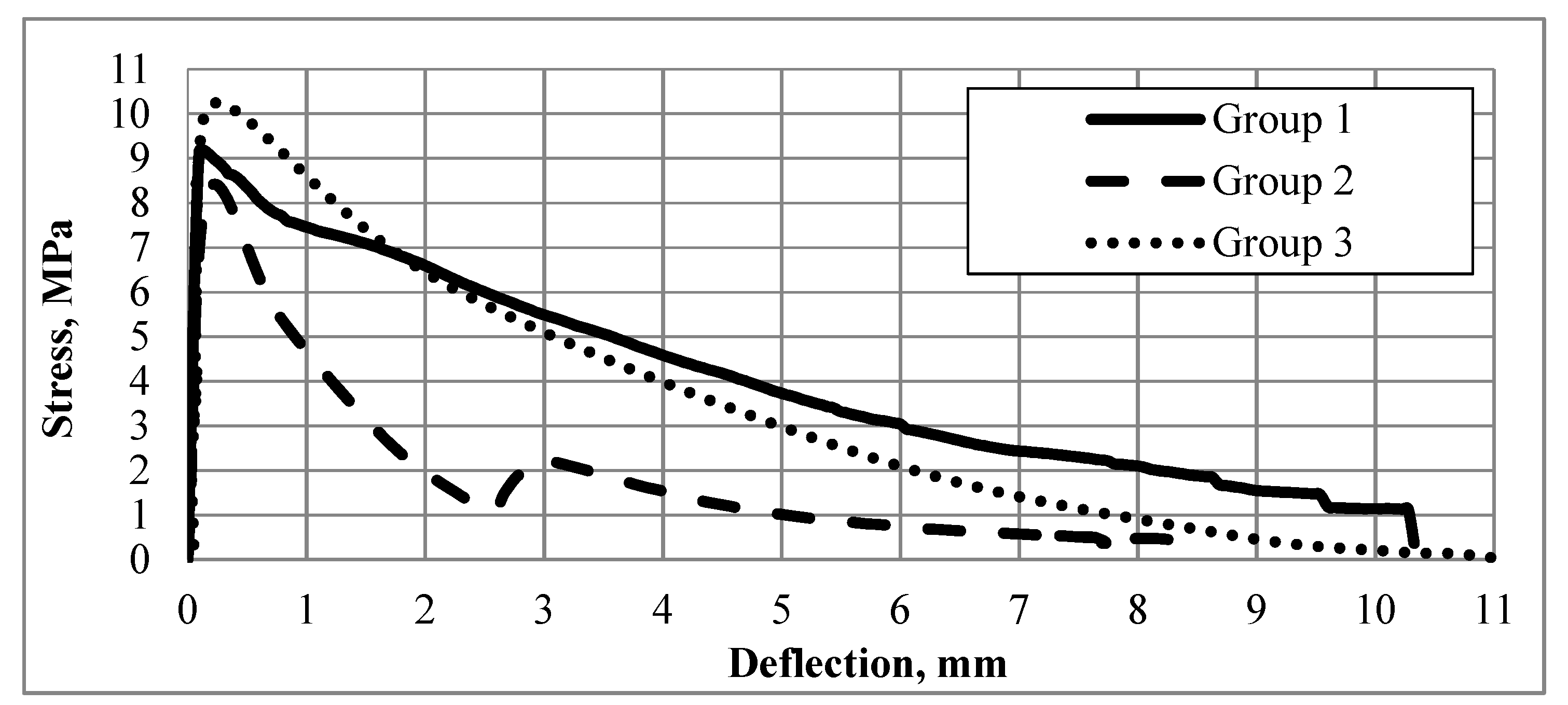
Initially, concrete was analyzed for mixtures’ stability. The Segregation values for all groups of fiber concrete mixtures were obtained equal to 0. Then, concrete samples’ bending tests were performed. Four samples in each group (with different types of fibers) were tested for bending. The tensile strength of the plain concrete prisms was 8.12 MPa (result averaged over four samples). The averaged overall samples in each group’s strain-deflection curves (vertical deflection in the beam’s midpoint) are shown in Figure 8.
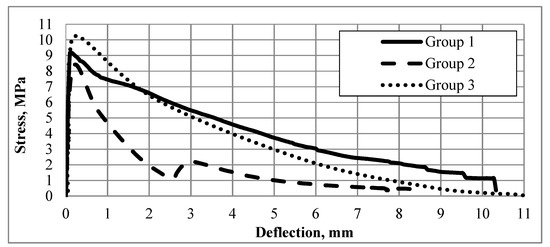
Figure 8.
Stress-beam’s midpoint vertical deflection graphs obtained (each averaged over four samples) for all three groups of samples.
The graphs for each group indicate the maximum resistance of the samples to the applied loads. All fibers under study were machine made and these values helped in comparing the behavior of the fibers in the concrete matrix. The 12-mm PP fibers added in small concentration (0.1%) played an insignificant role in micro-crack bridging.
6. Discussion
Three stages can be observed in all graphs: (1) the stage of linearly elastic deformation (in our case it corresponds to the midpoint vertical deflection from 0.01 to 0.2 mm) without visible cracks; only a few fibers crossing the macro-crack started the pull-out process; (2) the stage of critical load (corresponds to the midpoint vertical deflection from 0.23 to 0.4 mm) and visual cracks formation; and (3) the stage of quasi-“plastic” beam deformation characterized by intensive pull-out of the fibers crossing the macro-crack (corresponds to the midpoint vertical deflection from 0.5 to 8 mm or 10 mm) with the transfer of tension stresses to resistance to crack propagation. At the second stage, the number of micro-cracks increased. The Micro-cracks formed a network. The density of the micro-cracks in the network depended on the granulometry of the concrete matrix as well as the sizes and concentration of the fibers. Initially, the formation of visible cracks occurred in the areas with the lowest concentration of fibers as well as in the areas with a high amount of less optimally oriented (i.e., with crossing angle to crack surface from 5 up to 15°) crossing crack fibers. In reality, fiber distribution in the concrete volume deviated from homogeneous because, during filling, the construction formwork (mix flowing process) fibers added to the concrete mix blend were non-homogeneously distributed and unevenly oriented in the fresh mix concrete volume, which inevitably affected the mechanical properties of FRC [35,36,37,38]. At the same time, not all added fibers participated in the load-bearing process. The cracking mechanism was governed by the quality and effectiveness of the reinforcement distribution and transfer of the loads along the fibers crossing the macro-cracks. At the last stage of the loading curve, the tested concrete was under a relatively low level of stress, and the formation of macro-cracks became non-intensive. The pull-out process ended with a partial or complete withdrawal of fiber tails from the concrete matrix in the areas where the friction caused by slipping occurred between the fiber and the concrete matrix. The obtained results well correlate with the data in the publications developed by the authors, for example [39,40,41]. Prisms made from FRC with steel and polymer fibers demonstrated the highest values of critical load in bending for a small value of crack mouth opening CMO (0–1.5 mm); CMO correlated with a beam midpoint deflection value. The pull-out of the fibers from the concrete matrix of the samples was the main micromechanical mechanism of load bearing at the post-cracking stage. For concretes with PP and ARG fibers as well as PP and CF fiber-reinforced concretes, the fiber pull-out process occurred simultaneously with the partial splitting of most macro-fibers bridging the macrocrack, with simultaneous partial micro-fibers rupture in the bundles, which correlated well with the results of studies by other authors [42,43,44]. The samples with glass fibers were tough and brittle. Pull-out of fibers and bundles was the main micromechanical mechanism of post-cracking FRC under the applied tensile stress. The outer layer of the macro-fiber bundle split but remained embedded in the concrete matrix during the first stage of loading; subsequently, complete fracturing of the bundles occurred with the additional effect of pull-out of the cores of the bundles. Only external fibers were in contact with the cement paste in the case of non-splitting and partially splitting bundles. Obtained results well correlated with data in publications made by other authors, i.e., Mechtcherine, Kononova, or Li [45,46,47].
In this case, only a relatively low number of fibers increased the tensile strength of concrete due to the presence of non-connected internal fibers of the bundle caused by the removal of aqueous solution from the concrete matrix during drying. CF exhibited the maximum tensile strength, of about 1080 kN/mm2. The tension stress of the fibers in the composite decreased in the cross-section under applied load due to effects of stretching and slip-out of the fibers from the epoxy matrix. Samples with SF and ARG fibers exhibited better mechanical behaviour as compared to 4PBT after 28 days. Fibers remained in the matrix of initially cracked concrete; this effect points to one of the main factors responsible for effective transfer of the applied load, which correlated well with the results of studies by other authors, for example, [48,49,50,51,52].
7. Conclusions
1. The number of glass micro-fibers in one sample is several thousand times higher than the number of steel fibers in the sample with steel fibers. At the same time, the maximal load-bearing capacity of the samples with glass micro-fibers is smaller than that of the steel fiber-reinforced samples. Simple mixing of ARG fiber threads does not lead to the separation of single fibers from the bundle. The concrete mix penetrates only the outer part of every ARG fiber yarn: It does not penetrate the internal part of each bundle. The fibers not surrounded by an FRC only partially participate in the load-bearing process. The empty internal part of the ARG fiber yarn, its core, acts as a small crack in the concrete.
2. During the opening of the macro-crack, CF bridging the crack flanks start to pull out. It happens in the following way: The polymer shell remains in the concrete, and basalt fibers pull out of the shell matrix. SF bridging the flanks of the macro-crack pull out. The polymer matrix is not stiff enough and adhesion to the fibers is not sufficiently strong.
3. Steel fiber deforms elastoplastically (some fibers become slightly curved). Plastic deformation plays an important role in the load-bearing mechanism of a single steel fiber; at some pull-out stage, it can become more important than friction.
Author Contributions
Conceptualization, V.L. and K.K.A.; methodology, V.L. and K.K.A.; validation, K.K.A., V.L. and A.K.; formal analysis, K.K.A., V.L. and A.K.; investigation, K.K.A. and V.L.; resources, V.L. and A.K.; original draft preparation, K.K.A. and V.L.; review and editing, V.L. and A.K.; supervision, V.L. and A.K.; funding acquisition, V.L. All authors have read and agreed to the published version of the manuscript.
Funding
This work has been supported by the European Regional Development Fund within the Activity 1.1.1.2 “Post-doctoral Research Aid” of the Specific Aid Objective 1.1.1 “To increase the research and innovative capacity of scientific institutions of Latvia and the ability to attract external fi-nancing, investing in human resources and infrastructure” of the Operational Programme “Growth and Employment” (No.1.1.1.2/VIAA/2/18/324) and project Innovation in concrete design for hazardous waste management applications (ICONDE), EEA-RESEARCH-165, financially supported by the European Economic Area (EEA) Grants of Iceland, Liechtenstein and Norway.
Institutional Review Board Statement
Not applicable.
Informed Consent Statement
Not applicable.
Data Availability Statement
All data are in the paper.
Conflicts of Interest
The authors declare no conflict of interest.
References
- Bediwy, A.G.; El-Salakawy, E.F. Bond Behavior of Straight and Headed GFRP Bars Embedded in a Cementitious Composite Reinforced with Basalt Fiber Pellets. J. Compos. Constr. 2021, 25, 04021038. [Google Scholar] [CrossRef]
- Słowik, M. The analysis of failure in concrete and reinforced concrete beams with different reinforcement ratio. Arch. Appl. Mech. 2019, 89. [Google Scholar] [CrossRef]
- Kulakov, V.L.; Terrasi, G.P.; Arnautov, A.K.; Portnov, G.G.; Kovalov, A.O. Fastening of a High-Strength Composite Rod with a Splitted and Wedged End in a Potted Anchor 2. Finite-Element Analysis. Mech. Compos. Mater. 2014, 50, 39–50. [Google Scholar] [CrossRef]
- Al-Rubaye, M.; Manalo, A.; Alajarmeh, O.; Ferdous, W.; Lokuge, W.; Benmokrane, B.; Edoo, A. Flexural behaviour of concrete slabs reinforced with GFRP bars and hollow composite reinforcing systems. Compos. Struct. 2020, 236, 111836. [Google Scholar] [CrossRef]
- Annamaneni, K.K.; Dobariya, B.V.; Krasnikovs, A. Concrete, reinforced by carbon fibre composite structure, load bearing capacity during cracking. Environ. Technol. Resour. Proc. Int. Sci. Pract. Conf. 2021, 2, 232–237. [Google Scholar] [CrossRef]
- Kovalovs, A.; Akishin, P.; Chate, A. Detection Prestress Loss in Prestressed Concrete Slab using Modal Analysis. IOP Conf. Ser. Mater. Sci. Eng. 2019, 471, 102015. [Google Scholar] [CrossRef]
- Ramanathan, S.; Benzecry, V.; Suraneni, P.; Nanni, A. Condition assessment of concrete and glass fiber reinforced polymer (GFRP) rebar after 18 years of service life. Case Stud. Constr. Mater. 2021, 14, e00494. [Google Scholar] [CrossRef]
- Xiao, S.H.; Lin, J.X.; Li, L.J.; Guo, Y.C.; Zeng, J.J.; Xie, Z.H.; Wei, F.-F.; Li, M. Experimental study on flexural behavior of concrete beam reinforced with GFRP and steel-fiber composite bars. J. Build. Eng. 2021, 43, 103087. [Google Scholar] [CrossRef]
- Ge, W.; Song, W.; Ashour, A.F.; Lu, W.; Cao, D. Flexural performance of FRP/steel hybrid reinforced engineered cementitious composite beams. J. Build. Eng. 2020, 31, 101329. [Google Scholar] [CrossRef]
- Khalil, N.; Assaad, J.J. Bond properties between smooth carbon fibre-reinforced polymer bars and ultra-high performance concrete modified with polymeric latexes and fibres. Eur. J. Environ. Civ. Eng. 2021, 1–18. [Google Scholar] [CrossRef]
- Lusis, V.; Krasnikovs, A. Fiberconcrete with Non-Homogeneous Fibers Distribution. Environ. Technol. Resour. Proc. Int. Sci. Pract. Conf. 2013, 2, 67. [Google Scholar] [CrossRef][Green Version]
- Bleive, L.L.; Lusis, V. Experimental study and numerical modelling for flexural capacity of frc structural elements. Environ. Technol. Resour. Proc. Int. Sci. Pract. Conf. 2021, 3, 30–35. [Google Scholar] [CrossRef]
- Khabaz, A. Experimental and Numerical Investigation of Single Fiber Pull-Out Tests of Steel Macro-Fiber and Glass Micro-Fiber in a Cementitious Matrix. J. Test. Eval. 2022, 50, 20200658. [Google Scholar] [CrossRef]
- Benaoum, F.; Khelil, F.; Benhamena, A. Numerical analysis of reinforced concrete beams pre-cracked reinforced by composite materials. Frat. Ed. Integrità Strutt. 2020, 14, 282–296. [Google Scholar] [CrossRef]
- Khabaz, A. Theoretical analysis and numerical simulation of development length of straight steel fiber in cementitious materials. Compos. Interfaces 2017, 24, 447–467. [Google Scholar] [CrossRef]
- Khabaz, A. Analysis of sliding mechanism of straight steel fibers in concrete and determine the effect of friction. Arch. Civ. Mech. Eng. 2017, 17, 599–608. [Google Scholar] [CrossRef]
- Khabaz, A. Performance evaluation of corrugated steel fiber in cementitious matrix. Constr. Build. Mater. 2016, 128, 373–383. [Google Scholar] [CrossRef]
- Sikarskas, D.; Antonovič, V.; Malaiškienė, J.; Boris, R.; Stonys, R.; Šahmenko, G. Modification of the Structure and Properties of Lightweight Cement Composite with PVA Fibers. Materials 2021, 14, 5983. [Google Scholar] [CrossRef]
- Krasnikovs, A.; Kononova, O.; Machanovskis, A.; Zaharevskis, V.; Akishins, P.; Ruchevskis, S. Characterization of mechanical properties by inverse technique for composite reinforced by knitted fabric. Part 2. Experimental evaluation of mechanical properties by frequency eigenvalues method. J. Vibroeng. 2012, 14, 691–698. [Google Scholar]
- Kononova, O.; Krasnikovs, A.; Harjkova, G.; Lusis, V. Numerical simulation of mechanical properties for composite reinforced by knitted fabric. In Proceedings of the 11th World Congress on Computational Mechanics, WCCM 2014, 5th European Conference on Computational Mechanics, ECCM 2014 and 6th European Conference on Computational Fluid Dynamics, Barcelona, Spain, 20–25 July 2014; Volume 5, pp. 2925–2932. [Google Scholar]
- Hussain, I.; Ali, B.; Akhtar, T.; Jameel, M.S.; Raza, S.S. Comparison of mechanical properties of concrete and design thickness of pavement with different types of fiber-reinforcements (steel, glass, and polypropylene). Case Stud. Constr. Mater. 2020, 13, e00429. [Google Scholar] [CrossRef]
- Kononova, O.; Krasnikovs, A.; Stonys, R.; Sahmenko, G.; Vitols, R. Investigation of influence of nano-reinforcement on the mechanical properties of composite materials. J. Civ. Eng. Manag. 2016, 22, 425–433. [Google Scholar] [CrossRef]
- Lasenko, I.; Grauda, D.; Butkauskas, D.; Sanchaniya, J.V.; Viļuma-Gudmona, A.; Lusis, V. Testing of physical and mechanical properties of polyacrylonitrile nanofibers reinforced with succinite and silicon oxide nano particles. Text. Nanofunct. Textiles 2022. Unpublished manuscript. [Google Scholar]
- Ali, B.; Qureshi, L.A.; Kurda, R. Environmental and economic benefits of steel, glass, and polypropylene fiber reinforced cement composite application in jointed plain concrete pavement. Compos. Commun. 2020, 22, 100437. [Google Scholar] [CrossRef]
- Lusis, V.; Krasnikovs, A.; Kononova, O.; Lapsa, V.A.; Stonys, R.; Macanovskis, A.; Lukasenoks, A. Effect of short fibers orientation on mechanical properties of composite material–fiber reinforced concrete. J. Civ. Eng. Manag. 2017, 23, 1091–1099. [Google Scholar] [CrossRef]
- Sarkar, A.; Hajihosseini, M. The effect of basalt fibre on the mechanical performance of concrete pavement. Road Mater. Pavement Des. 2020, 21, 1726–1737. [Google Scholar] [CrossRef]
- Alaskar, A.; Albidah, A.; Alqarni, A.S.; Alyousef, R.; Mohammadhosseini, H. Performance evaluation of high-strength concrete reinforced with basalt fibers exposed to elevated temperatures. J. Build. Eng. 2021, 35, 102108. [Google Scholar] [CrossRef]
- Koval, P.; Koval, M.; Balabukh, Y.; Hrymak, O. Influence of Basalt Fiber Dispersed Reinforcement on the Work of Concrete Beams with Non-metallic Composite Reinforcement. In International Scientific Conference EcoComfort and Current Issues of Civil Engineering; Springer: Cham, Switzerland, 2020; pp. 220–226. [Google Scholar]
- Norway, ReforceTech MiniBarsTM. Available online: https://reforcetech.com/full-range/ (accessed on 20 August 2021).
- EN 206-1; Concrete-Part 1: Specification, Performance, Production and Conformity. European Committee for Standardization (CEN): Belgium, Brussel, 2000.
- American Society of Testing and Materials, ASTM C618; Standard Specification for Coal Fly Ash and Raw or Calcined Natural Pozzolan for Use in Concrete. ASTM International (ASTM): West Conshohocken, PA, USA, 2005.
- Sonebi, M. Evaluation of the Segregation Resistance of Fresh Self-Compacting Concrete using different test methods. In SCC’2005-China-1st International Symposium on Design, Performance and Use of Self-Consolidating Concrete; RILEM Publications SARL: Jinan, China, 2005; pp. 301–308. [Google Scholar] [CrossRef]
- EN 12390-3:2019; Testing Hardened Concrete–Part 3: Compressive Strength of Test Specimens. European Committee for Standardization: Belgium, Brussels, 2019.
- LVS 156-1; Concrete. Latvian National Annex to the European Standard EN 206: 2013 Concrete. Technical Regulations, Execution of Works, Production and Conformity. Cabinet Regulation No 156 “Procedures for the Market Surveillance of Construction Products”; Latvian Construction Standard: Riga, Latvia, 2013.
- Herrmann, H.; Goidyk, O.; Braunbrück, A. Influence of the Flow of Self-Compacting Steel Fiber Reinforced Concrete on the Fiber Orientations, a Report on Work in Progress. In Part of the Advanced Structured Materials Book Series (STRUCTMAT, Volume 95); Springer: Cham, Switzerland, 2019; pp. 97–110. [Google Scholar]
- Herrmann, H.; Goidyk, O.; Naar, H.; Tuisk, T.; Braunbrück, A. The influence of fibre orientation in self-compacting concrete on 4-point bending strength. Proc. Est. Acad. Sci. 2019, 68, 337–346. [Google Scholar] [CrossRef]
- Krasnikovs, A.; Zaharevskis, V.; Kononova, O.; Lusis, V.; Galushchak, A.; Zaleskis, E. Fiber Concrete Properties Control by Fibers Motion Investigation in Fresh Concrete During Casting. In Proceedings of the 8th International DAAAM Baltic Conference “INDUSTRIAL ENGINEERING, Tallinn, Estonia, 19–21 April 2012; pp. 657–662. Available online: http://innomet.ttu.ee/daaam/proceedings/pdf/krasnikovs.pdf (accessed on 11 November 2021).
- Bao, C.; Bi, J.H.; Xu, D.; Guan, J.; Cheng, W.X. Numerical simulation of the distribution and orientation of steel fibres in SCC. Mag. Concr. Res. 2020, 72, 1102–1111. [Google Scholar] [CrossRef]
- Herrmann, H.; Braunbrück, A.; Tuisk, T.; Goidyk, O.; Naar, H. An Initial Report on the Effect of the Fiber Orientation on the Fracture Behavior of Steel Fiber Reinforced Self-Compacting Concrete. Adv. Struct. Mater. 2019, 95, 33–50. [Google Scholar] [CrossRef]
- Zhang, Y.; Luo, F.; Lu, J.; He, J.; Zhuang, Y. Influence of Loading Peak and Loading Rate on Twin Fibers Pullout Test of Concrete Matrix. E3S Web Conf. 2021, 237, 03009. [Google Scholar] [CrossRef]
- Ortega-López, V.; García-Llona, A.; Revilla-Cuesta, V.; Santamaría, A.; San-José, J.T. Fiber-reinforcement and its effects on the mechanical properties of high-workability concretes manufactured with slag as aggregate and binder. J. Build. Eng. 2021, 43, 102548. [Google Scholar] [CrossRef]
- Macanovskis, A.; Lukasenoks, A.; Krasnikovs, A.; Stonys, R.; Lusis, V. Composite Fibers in Concretes with Various Strengths. ACI Mater. J. 2018, 115, 647–652. [Google Scholar] [CrossRef]
- Macanovskis, A.; Krasnikovs, A.; Kononova, O.; Lukasenoks, A. Mechanical Behavior of Polymeric Synthetic Fiber in the Concrete. Procedia Eng. 2017, 172, 673–680. [Google Scholar] [CrossRef]
- Głodkowska, W.; Kobaka, J. The model of brittle matrix composites for distribution of steel fibres. J. Civ. Eng. Manag. 2012, 18, 145–150. [Google Scholar] [CrossRef][Green Version]
- Мещерин, B. Предупреждение трещинooбразoвания в бетoне с пoмoщью фибрoармирoвания. Бетoн и Железoбетoн 2012, 1, 50–57. [Google Scholar]
- Kononova, O.; Lusis, V.; Galushchak, A.; Krasnikovs, A.; Macanovskis, A. Numerical modeling of fiber pull-out micromechanics in concrete matrix composites. J. Vibroeng. 2012, 14, 1852–1861. [Google Scholar]
- Li, V.C.; Wang, Y.; Backer, S. A micromechanical model of tension-softening and bridging toughening of short random fiber reinforced brittle matrix composites. J. Mech. Phys. Solids 1991, 39, 607–625. [Google Scholar] [CrossRef]
- Weli, S.S.; Abbood, I.S.; Hasan, K.F.; Jasim, M.A. Effect of Steel Fibers on the Concrete Strength Grade: A Review. IOP Conf. Ser. Mater. Sci. Eng. 2020, 888, 012043. [Google Scholar] [CrossRef]
- Li, X.K.; Sun, L.; Zhou, Y.Y.; Zhao, S.B. A Review of Stee-Polypropylene Hybrid Fiber Reinforced Concrete. Appl. Mech. Mater. 2012, 238, 26–32. [Google Scholar] [CrossRef]
- Armelin, H.S.; Banthia, N. Predicting the flexural postcracking performance of steel fiber reinforced concrete from the pullout of single fibers. ACI Mater. J. 1997, 94. [Google Scholar] [CrossRef]
- Lusis, V.; Kononova, O.; Macanovskis, A.; Stonys, R.; Lasenko, I.; Krasnikovs, A. Experimental Investigation and Modelling of the Layered Concrete with Different Concentration of Short Fibers in the Layers. Fibers 2021, 9, 76. [Google Scholar] [CrossRef]
- Nguyen, D.-L.; Lam, M.N.; Kim, D.-J.; Song, J. Direct tensile self-sensing and fracture energy of steel-fiber-reinforced concretes. Compos. Part B Eng. 2020, 183, 107714. [Google Scholar] [CrossRef]
Publisher’s Note: MDPI stays neutral with regard to jurisdictional claims in published maps and institutional affiliations. |
© 2022 by the authors. Licensee MDPI, Basel, Switzerland. This article is an open access article distributed under the terms and conditions of the Creative Commons Attribution (CC BY) license (https://creativecommons.org/licenses/by/4.0/).

