Article

Ultra-Long-Term Reliable Encapsulation Using an Atomic Layer Deposited HfO2/Al2O3/HfO2 Triple-Interlayer for Biomedical Implants

1
Centre for Microsystems Technology (CMST), imec and Ghent University, Technologiepark 126, 9052 Gent, Belgium
2
Pacific Northwest National Laboratory, Richland, WA 99352, USA
*
Authors to whom correspondence should be addressed.
Coatings 2019, 9(9), 579; https://doi.org/10.3390/coatings9090579
Submission received: 19 August 2019 / Revised: 8 September 2019 / Accepted: 10 September 2019 / Published: 12 September 2019

Abstract

:
Long-term packaging of miniaturized, flexible implantable medical devices is essential for the next generation of medical devices. Polymer materials that are biocompatible and flexible have attracted extensive interest for the packaging of implantable medical devices, however realizing these devices with long-term hermeticity up to several years remains a great challenge. Here, polyimide (PI) based hermetic encapsulation was greatly improved by atomic layer deposition (ALD) of a nanoscale-thin, biocompatible sandwich stack of HfO2/Al2O3/HfO2 (ALD-3) between two polyimide layers. A thin copper film covered with a PI/ALD-3/PI barrier maintained excellent electrochemical performance over 1028 days (2.8 years) during acceleration tests at 60 °C in phosphate buffered saline solution (PBS). This stability is equivalent to approximately 14 years at 37 °C. The coatings were monitored in situ through electrochemical impedance spectroscopy (EIS), were inspected by microscope, and were further analyzed using equivalent circuit modeling. The failure mode of ALD Al2O3, ALD-3, and PI soaking in PBS is discussed. Encapsulation using ultrathin ALD-3 combined with PI for the packaging of implantable medical devices is robust at the acceleration temperature condition for more than 2.8 years, showing that it has great potential as reliable packaging for long-term implantable devices.

Graphical Abstract

1. Introduction

An implantable medical device that is capable of continuous disease diagnosis and even treatment represents a class of an emerging research area thanks to the recent advances in soft and flexible/stretchable electronics [1,2,3,4,5,6]. Today, the vast majority of implanted electronic devices (e.g. pacemakers, cochlear implants) use hard biocompatible materials such as glass, ceramics, metal, or metal alloys to encapsulate and protect the internal electronic components, chips, and/or power sources [3]. However, the need for flexible, softer, and miniaturized devices has increased due to several additional requirements from a (bio)medical point of view: (1) a close match between the mechanical properties of the implant and the targeted soft tissue or organ; (2) the creation of small electrodes that are directly accessible to the targeted body environment for stimulation, recording, and analyses of biomolecules; (3) small devices for minimal invasive implantation, scar tissue formation, and foreign body reaction (FBR).
These conditions point toward the direction of polymer materials. Polydimethylsiloxane (PDMS), PI, and parylene(s) are being explored by a large amount of researchers for these purposes [7,8,9,10]. Despite the biocompatibility and good mechanical properties, one major disadvantage of these polymers for encapsulation is their low hermeticity towards moisture and water [11,12]. This is generally expressed as water vapor transmission rates (WVTR) in the order of 1–100 g·m−2·day−1 [13]. For long term implants (>1 month), this can lead to failure of the device and leaching of toxic (corrosion) products from the implant to the body environment.
Over the last decade, considerable effort has been devoted to the use of atomic layer deposition (ALD) oxide layers to achieve hermetic encapsulation with long-term reliability and ultra-thinness (5 to a few hundred nm) for applications such as organic light-emitting diode (OLED) encapsulation [14,15], corrosion protection of metals [16,17], and barrier layer development for (electronic) implants [18,19].
In general, ALD layers have three important properties that make them ideal to serve as a barrier layer: they are nearly pin-hole free, are highly conformal, and a limited thickness (5–100 nm) is required [20,21]. Deposition of ALD layers on polymers is also possible. However, the deposition temperature of the ALD process must be decreased to avoid thermal decomposition of the polymers.
The most extensive research is performed on Al2O3 layers thanks to its low moisture permeability as well as its excellent thermal and mechanical properties [13,22,23,24]. For example, single-layered 20 nm ALD Al2O3 possesses superior WVTR in the order of 10−3 g·m−2·day−1 in a few days [25]. However, Al2O3 easily dissolves through hydrolysis when directly exposed to aqueous solutions [17,25,26,27,28]. Researchers show that the Al2O3 is a good moisture barrier for up to 24 h at room temperature, however this layer later deteriorates as it starts to dissolve in solutions [25,27]. Therefore, other ALD oxides like TiO2 [17,22], SiO2 [6,29], and HfO2 [25,30] have been investigated as an alternative layer or capping layer of Al2O3 to increase the stability and barrier properties in a liquid water environment. In the latter case, Al2O3 is still very useful as a moisture and ion barrier for the total stack.
In this contribution, we use HfO2 as a capping layer on both sides of the Al2O3 layer (ALD-3) to largely improve the stability towards a liquid water environment. HfO2 is chemically inert and insoluble in aqueous solutions [22,28,31]. However, the WVTR of single-layered 20 nm ALD HfO2 is worse than the Al2O3, in the order of magnitude 10−1 g·m−2·day−1 [25]. Hence, the presence of Al2O3 is still necessary. Therefore, capping the HfO2 and Al2O3 as a hermetic and stable barrier to stop moisture is adopted in this research.
BPDA-PPD polyimide (hereinafter referred to as PI) has been used as a substrate for flexible electronics and implantable medical devices for a long time [32,33,34,35,36]. The biocompatibility of polyimide has been proved in many in vitro and in vivo researches [34,37,38].
In this work, we investigate the properties of a biomedical encapsulation material stack with long-term stability based on a polyimide moisture barrier and a thin, sandwich inter-layer of HfO2/Al2O3/HfO2 (ALD-3). We compare it with individual or separate parts of the stack: Al2O3, ALD-3, and PI. The tri-layered ALD-3 extends the lifetime of Al2O3 from 2 to 62 days in an accelerated test in PBS solution at 60 °C. Our PI/ALD-3/PI encapsulation exhibits an impressive lifetime over 1028 days at 60 °C in PBS (equivalent to over 5140 days at 37 °C). This is by far the longest lifetime of an ultrathin biomedical encapsulation material to the best of our knowledge.

2. Materials and Methods

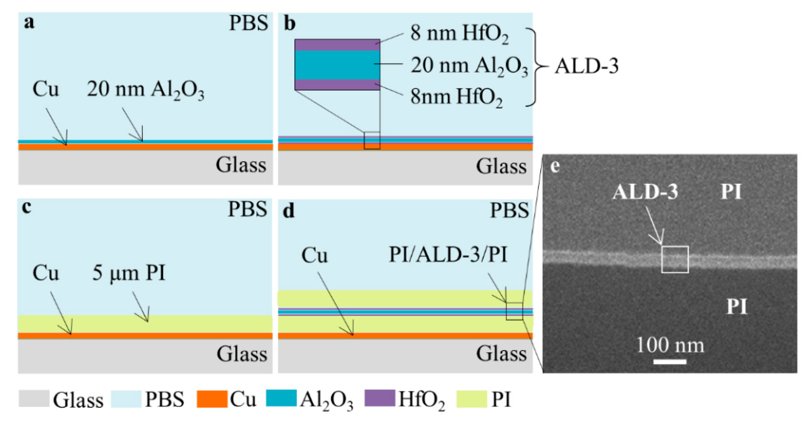
2.1. Sample Preparation

A thin copper film (1 μm) was deposited on cleaned glass substrates with a plasma magnetron sputter instrument (SCM600, Alcatel, France) using titanium tungsten (TiW) as an adhesion layer (50 nm). The copper film was used as the underlying material for evaluating the performance of the tested barriers since copper is known to be highly vulnerable to corrosion fluid such as PBS. Photolithography and wet etching was used to pattern the copper in a rectangular shape (1 cm × 2 cm).
A layer of 5 μm PI (HD2611, HD microsystems) was spin-coated with 3000 rpm for 30 s on a glass substrate with the copper test pattern after pre-treatment with adhesion promotor VM652. A reactive ion etching treatment (O2 and CHF3, 150 W) was performed on the PI surface to roughen the surface and to form functional groups, which improved the adhesion toward HfO2. Subsequently, a sandwich layer of 8 nm HfO2, 20 nm Al2O3 and again 8 nm HfO2 was deposited in a single deposition by thermal ALD at 250 °C using a Savannah instrument from Ultratech (Waltham, MA, USA). To promote the adhesion of the second PI layer on the surface of HfO2, 3-animopropyltriethoxysilane (APTES) treatment was applied. A more detailed barrier deposition and adhesion promotor treatment process have been previously reported [32]. The build-up of the four tested barriers is shown in Figure 1a–d and a cross-section of the PI/ALD-3/PI inspected by FIB-SEM (FEI Nova 600, Hillsborough, OR, USA) is shown in Figure 1e.

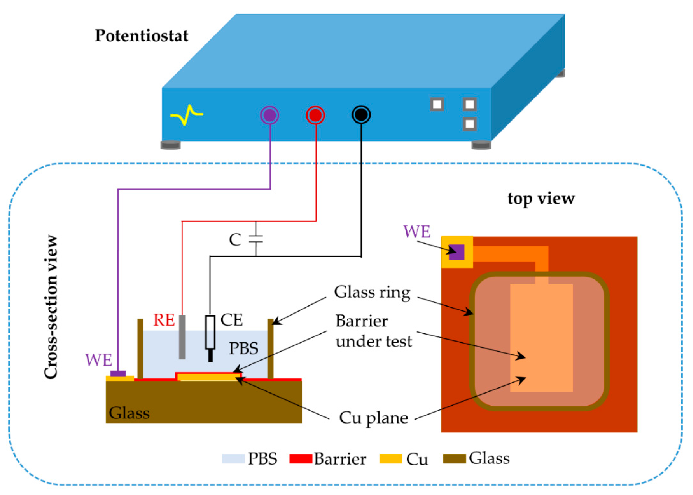
2.2. Experimental Setup

Soaking tests were performed at 60 °C in a digitally controlled oven (Horo Ovens, Ostfildern, Germany) to accelerate the degradation of the coating barriers. Temperature variations from sample to sample were minimized to ±0.5 °C by placing all the test samples on the same shelf inside the oven. Electrochemical impedance spectroscopy (EIS) has been widely employed to evaluate the performance of thin film layers [39,40]. Here, the EIS measurement was performed to investigate the degradation of barriers by monitoring the corrosion behavior of the copper. The EIS measurement was performed by a potentiostat (Bio-Logic VSP, Seyssinet, France) and data were recorded by EC-Lab software (version 10.32). The measurement was carried out using a three-electrode configuration with a platinum mesh as the counter electrode (CE), Ag/AgCl (NaCl saturated) as the reference electrode (RE), and copper as the working electrode (WE). All the EIS tests were carried out at room temperature. For a copper sample with perfectly insulating coating, it is difficult to obtain a stable value of the open-circuit potential (OCP) [39]. Therefore, the OCP was determined on bare Cu samples and was used as a reference for the EIS. The EIS measurements were performed at the OCP in a single sine curve of 50 mV with a frequency ranging from 0.3 Hz to 300 kHz with 10 data points in each decade.
The EIS test was employed to monitor the degradation process of the layers soaking in PBS and to determine the long-term moisture barrier property of the ALD Al2O3, ALD-3, PI, and PI/ALD-3/PI thin films. The EIS test schematic is shown in Figure 2. The counter electrode and the reference electrode were immersed in PBS. The working electrode was connected to the copper. To quantify the copper corrosion of the samples soaking in PBS with EIS, an appropriate equivalent circuit is necessary.
During the test period, a low current module was installed for the potentiostat, which extended the current resolution from 760 pA down to 76 fA. A comparison of the measurements curve with and without the low current module is shown in Figure S1.
A backside light optical microscope (Zeiss Stemi 2000C, Oberkochen, Germany) observation was applied to monitor the corrosion holes produced in the copper during exposure to the PBS solution. The observation zone (1 cm × 2 cm) for each sample was monitored ex-situ after removal of the PBS solution. A light source with 3000 cd was connected to a light distributor as a backside light source for the observation.

3. Results and Discussion
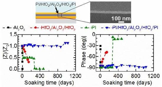
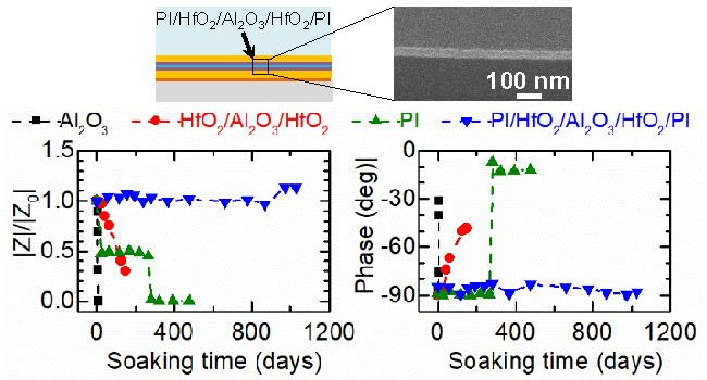
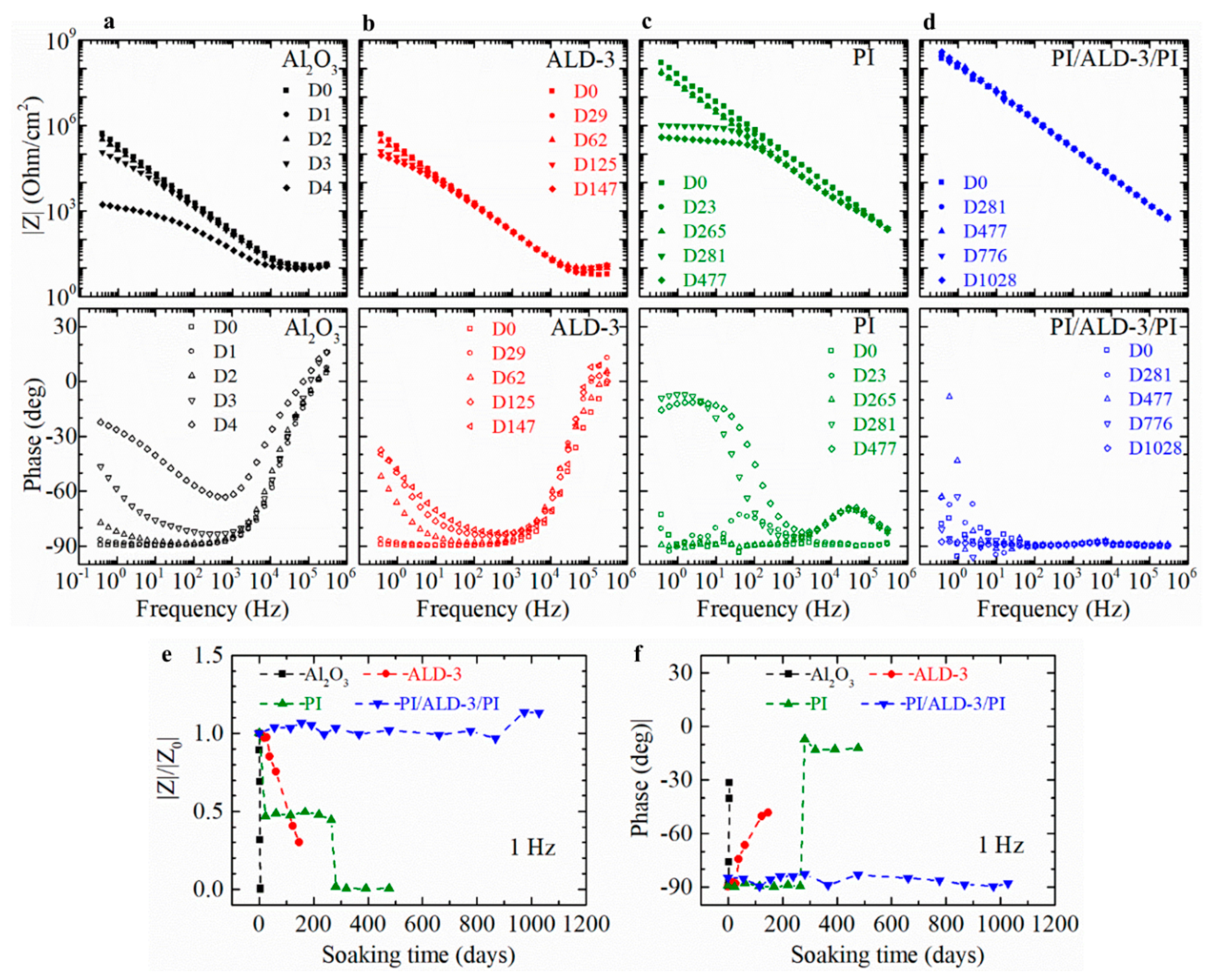
3.1. EIS

The initial impedance and the phase of each sample were measured at room temperature. The impedance and the phase changes in the low-frequency region are dominated by the properties of the barrier, e.g., the capacitance and the resistance of the barrier, and the polarization resistances [39,41]. Hence, the data points at 1 Hz were selected as reference values. We define the lifetime of a barrier as the soaking time at 50% loss of impedance (at 1 Hz) compared to the initial impedance.
Figure 3a shows the impedance and the corresponding measured phase angle of copper coated with 20 nm ALD Al2O3 soaked in PBS solution at 60 °C over a period of 4 days. The initial impedance curve shows a straight line with a negative slope and a phase angle of −90° at low-frequency region, exhibiting a pure capacitive behavior. Taking the value at 1 Hz, the impedance decreased two orders of magnitude during the 4 day soaking period. Meanwhile, the phase angle shifted from −90° to −30°. The significant changes of the impedance and the phase indicate that the barrier property of the Al2O3 layer decreased drastically after 4 days. To prevent the Al2O3 from hydrolyzing, HfO2/Al2O3/HfO2 (ALD-3) was applied as an optimized moisture barrier. The impedance of ALD-3 at a low-frequency region decreased from about 105 to 104 ohms (1 Hz) after 147 days of soaking (Figure 3b). The corresponding phase angle at 1 Hz increased from −90° to −47° (Figure 3b).
In a previous paper, we showed that a 16 μm PI (HD2611) has a high WVTR of 4.3 g·m−2·day−1 while ALD-3 coated on the same thickness polyimide resulted in a significant improvement of WVTR to less than 5 × 10⁻⁴ g·m−2·day−1 [4]. The initial EIS measurement of the PI layer showed that it had good barrier properties at the beginning of soaking, as shown in the curve D0 in Figure 3c. The capacitance of the PI coating increased as it absorbed moisture since water has a higher dielectric constant (εr = 78) [42] than PI (εr = 2.9) [43], resulting in a slightly decreased impedance. At the final degradation stage, the impedance at the low-frequency region dropped to the order of 105 ohms. Meanwhile, the phase angle increased from −90° close to −10° (Figure 3c), causing the samples to fail. On the other hand, the PI/ALD-3/PI barrier was robust for 1028 days, and no failure signal can be detected (Figure 3d).
Figure 3e shows the relative impedance at 1 Hz compared to the initial impedance versus the soaking period for the four barrier layers. Figure 3f shows their phase angle shifted at 1 Hz during the soaking period. The Al2O3 exhibited the fastest degradation, consistent with the hydrolysis of the layer. The ALD-3 remained stable during the initial 29 days and then degraded gradually over time, indicating that the properties of the barrier changed and the copper plane started to be exposed to the PBS solution. The PI barrier properties degraded dramatically at the beginning of soaking and then stabilized to 0.5 (Z/Z0) until day 267, followed by a second deep decrease during the following two weeks. This indicates that the PI layer protected copper plane system had two different degradation stages. The results for the PI/ALD-3/PI film reveal that the impedance and the phase angle remain stable during exposure to PBS, indicating that the barrier was not affected by the soaking environment.
Minnikanti et al., Woods et al., and Forssell et al. have put effort into evaluating the lifetime of barriers Al2O3/parylene C, LCP, and parylene C/TiO2/Al2O/TiO2 at an acceleration temperature (60 °C) in PBS, respectively. These barriers performed well up to a few hundred days under similar acceleration conditions (Table 1) [12,44,45]. To the best of our knowledge, the soaking results reported in this paper represent an excellent long-term encapsulation and PI/ALD-3/PI has great potential for the development of long-term implantable medical electronic devices.

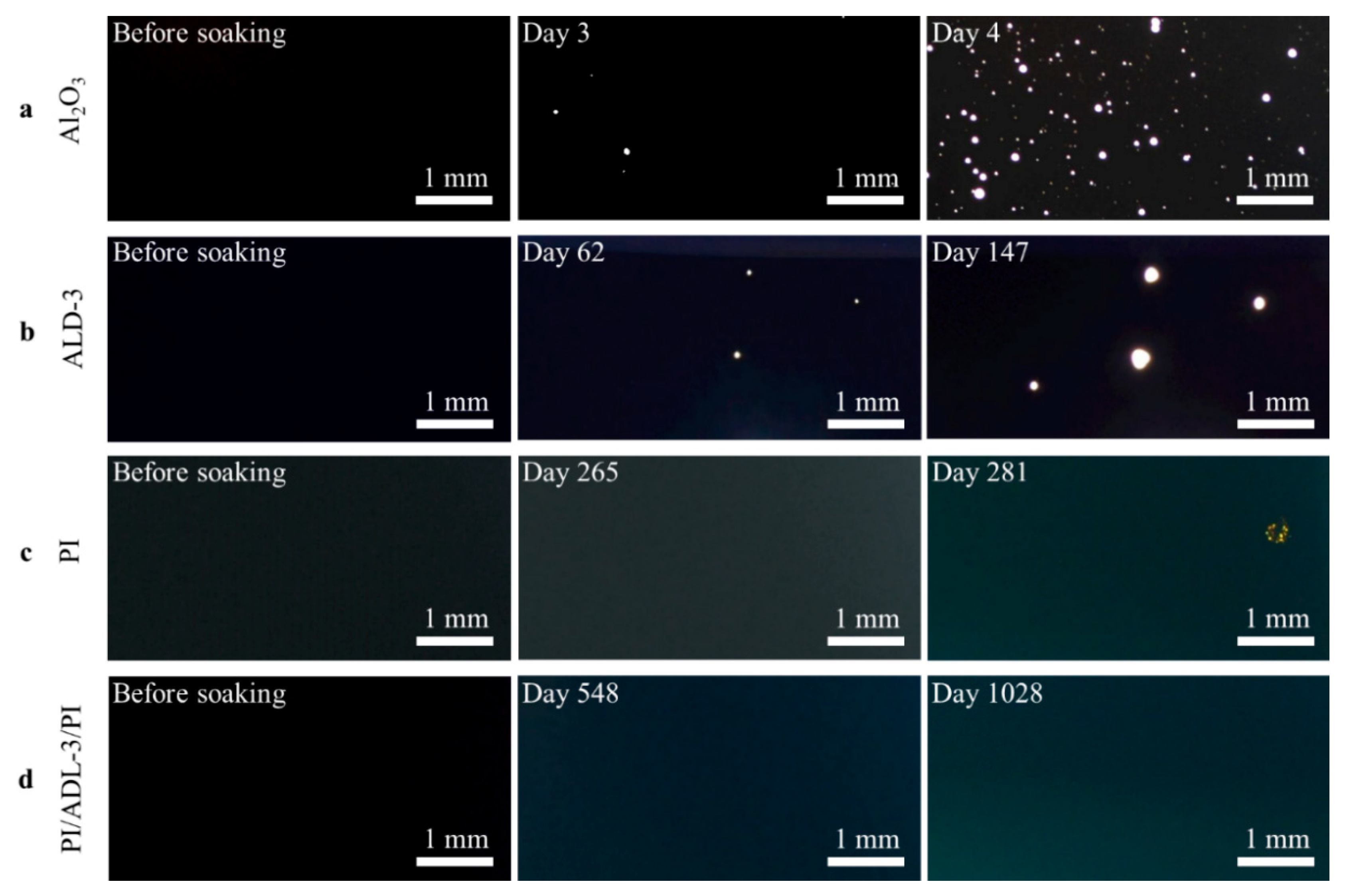
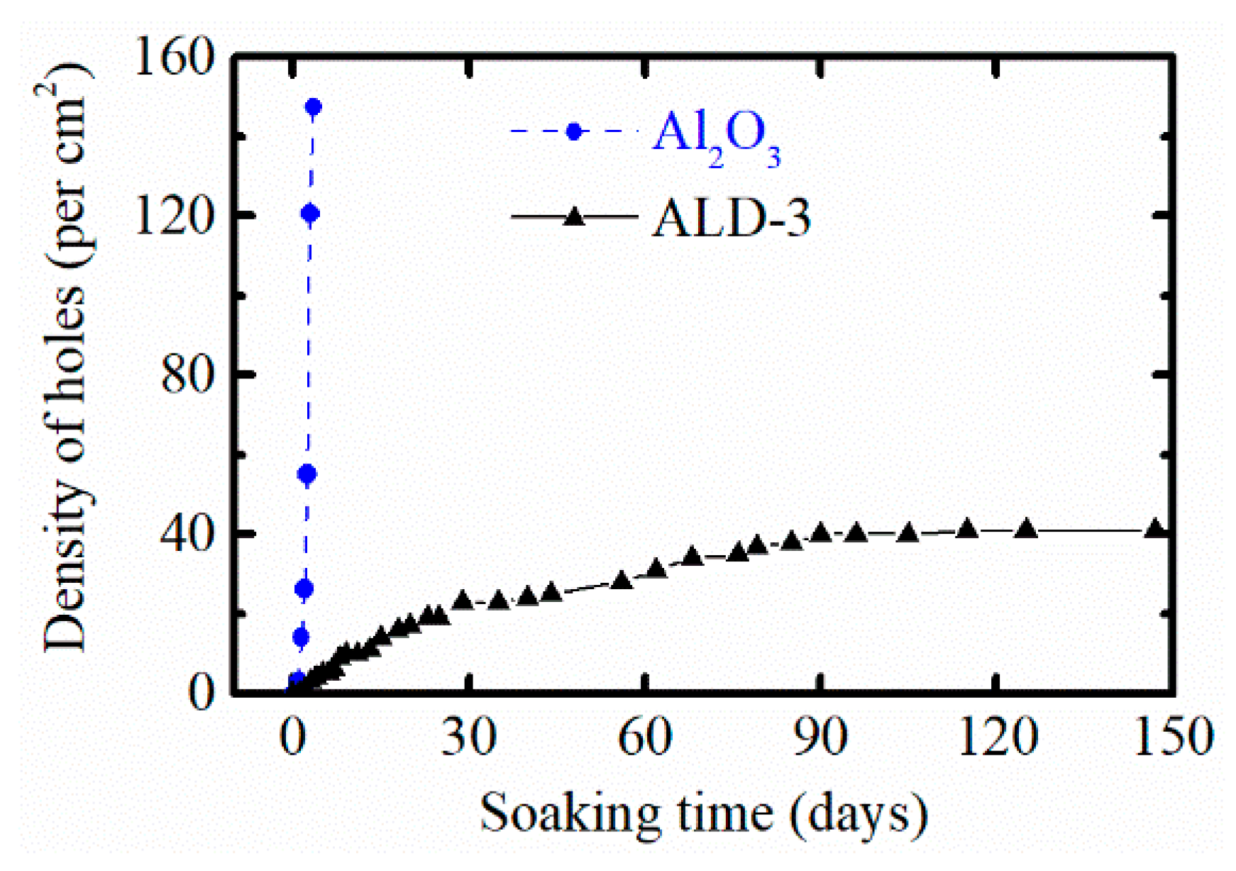
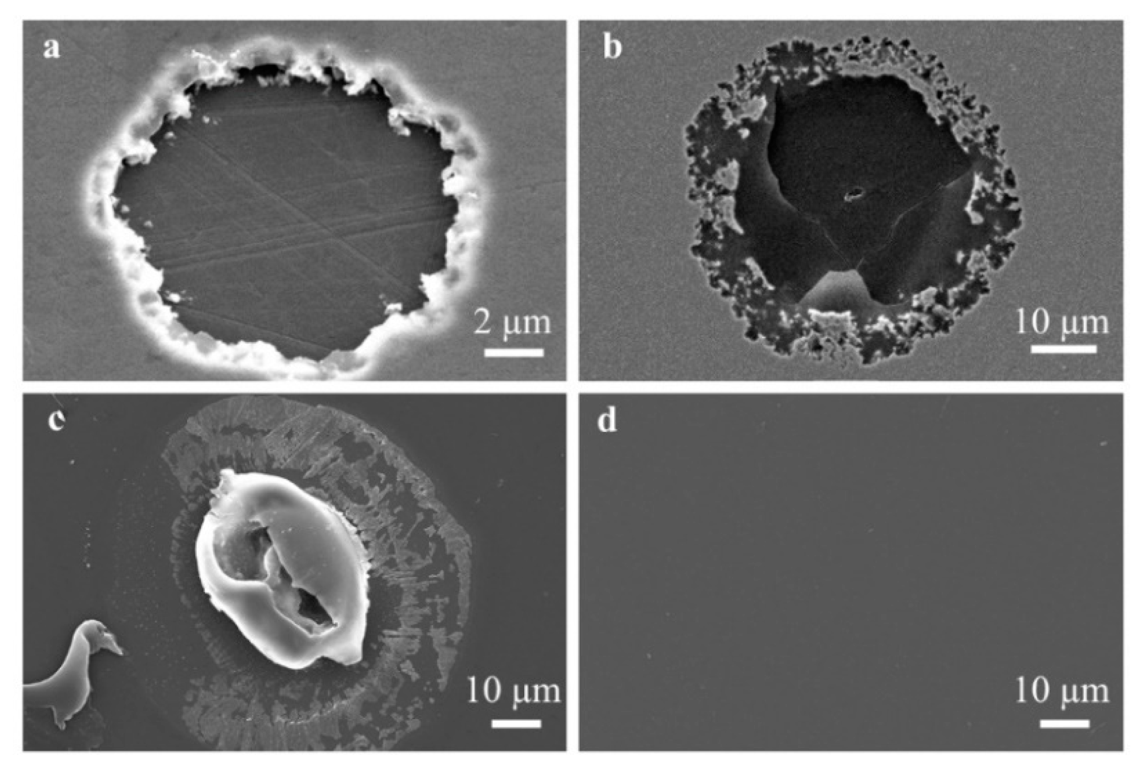
3.2. Optical Microscope Observation

As the barriers degraded during soaking in the PBS solution at 60 °C, corrosion holes started to appear in the copper. After that, their size quickly increased since copper is very sensitive towards corrosion in PBS medium. In Figure 4, microscope images at different time intervals are provided for the four tested barriers. All four tested barriers show no cavities in the copper at the beginning of the soaking test. Some small corrosion holes produced on Al2O3 protected copper are visible on day 3 and all the holes increased in size and more holes appeared on the copper over time (Figure 4a). In the case of the ALD-3 layer, a small number of corrosion holes appeared and increased in size and the density of the corrosion holes increased gradually during the first 90 soaking days. After 90 days, the hole density stabilized. This suggests that the corrosion holes may be attributed to local defects of the barrier since particle contamination could not be avoided during sample preparation. Another possible reason is that there were a few areas without good nucleation of the ALD Al2O3 layer, which resulted in minor voids in the ALD Al2O3 layer, which was also reported by Zhang et al. and Klumbies et al. [24,46,47]. We calculated the density of the corrosion holes on the copper (Figure 5) protected by ALD Al2O3 and ALD-3. The density of the corrosion holes in Al2O3 coated copper increased from 0 at the beginning to 148 per cm2 after four days. The density of the holes cannot be counted for day 5 since too many holes are present. In contrast, the density of the corrosion holes on the copper protected by ALD-3 reached 40 per cm2 on day 90 and remained stable in the following soaking period. Only 2 corrosion holes appeared on the copper with 5 μm PI protection on day 281, and no extra holes were found in the later soaking period (Figure 4c). For the PI/ALD-3/PI coated copper, no corrosion holes were observed during the 1028 days of soaking (Figure 4d).
To understand the failure mechanism of the barriers, the corrosion holes shown in Figure 4 were inspected using SEM. Figure 6 presents the SEM images of typical corrosion holes observed on the copper protected by ALD and PI coating. In general, the circular shape of the holes suggested that the corrosion started at the center of the circle. For the single ALD Al2O3 samples (Figure 6a), the Al2O3 is no longer present on top of the hole, suggesting that it dissolved in the PBS solution during soaking. In contrast, the barrier layer is still on the top of the hole in the ALD-3 samples (Figure 6b) and a small crack can be observed at the center of the corrosion hole. For the PI samples, corrosion first occurs near particles and defects in the coating. These may create a pathway for the PBS solution to the underlying copper, finally causing the copper corrosion (Figure 6c), while the PI/ALD-3/PI samples still work in perfect condition without any visible corrosion holes (Figure 6d).

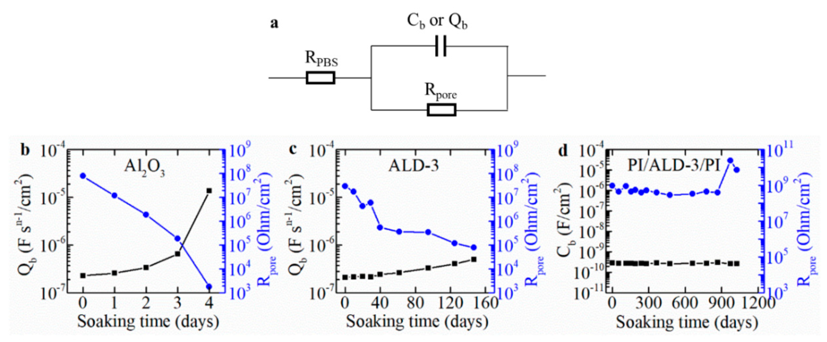
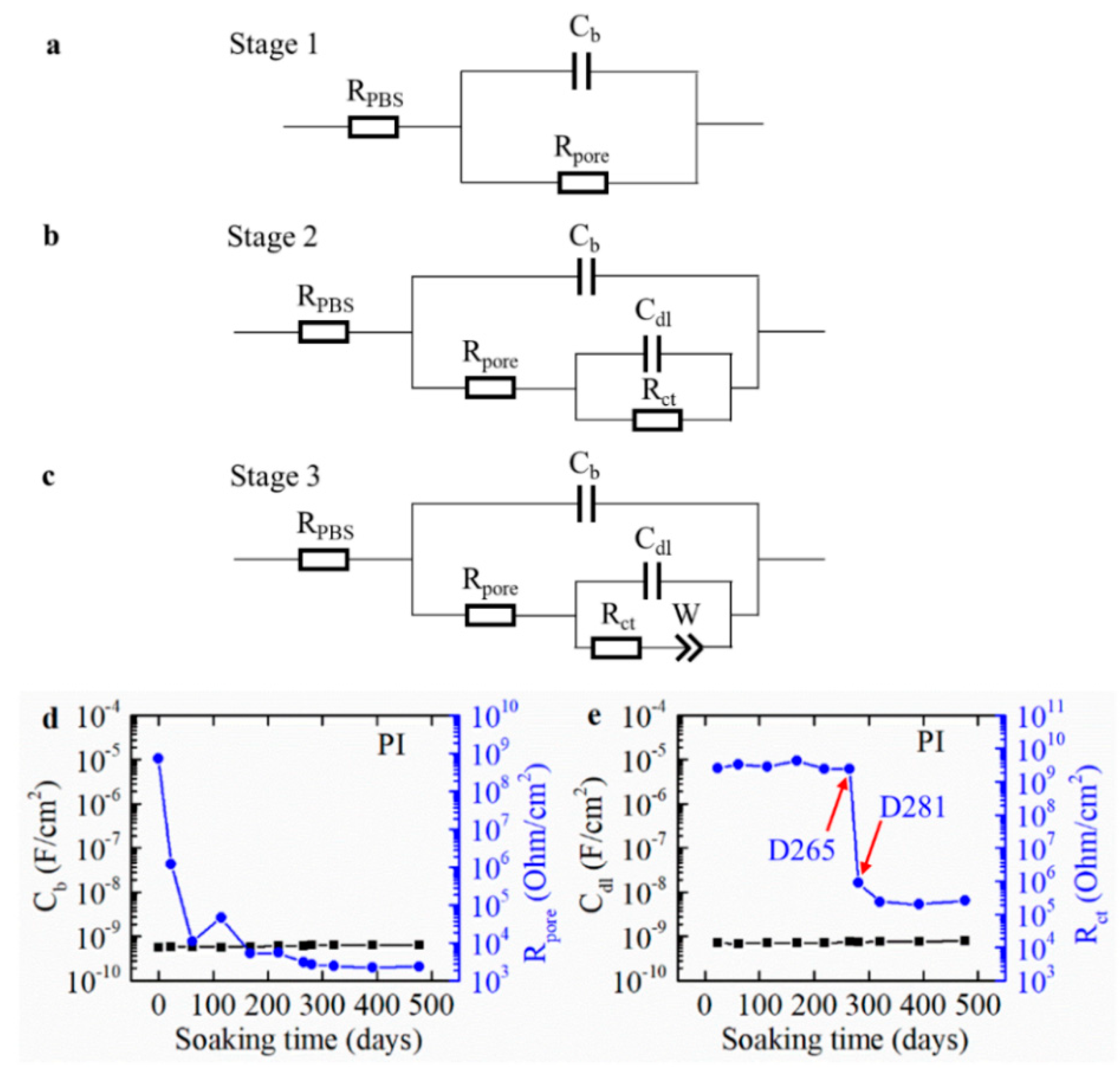
3.3. Equivalent Circuit Modeling of the Measured EIS Curve

A lumped-element circuit model (simplified Randles circuit) analysis was employed on the obtained EIS data to further interpret and analyze the effect of the barriers on the copper corrosion behavior in PBS [39,48,49]. The simplified Randles circuit model, consisting of an electrolyte resistance RPBS in series with a parallel combination of a barrier capacitance Cb or a constant phase element (Qb) and pore resistance Rpore, was used to fit the EIS measurement results (Figure 7a). A barrier capacitance Cb was applied to the simulation of PI degradation as the 5 µm PI coating layer behaved like a perfect capacitor. In contrast, a constant phase element Qb was employed to the model of ALD coating layer degradation as the pores in the ALD layers make the layers perform like an imperfect capacitor.
The theoretical capacitance value of the four test cases was calculated based on the double layer capacitance equation, as shown in Equation (1).
C = ε 0 ε r A d
where C is the capacitance of barriers in farads; A is the area of the barrier layer under test in square meters; ε0 is the electric constant (ε0 ≈ 8.854 × 10⁻¹² F⋅m−1); εr is the relative permittivity of the barriers; d is the thickness of the tested barriers in meters.
The thickness of ALD Al2O3 is about 20 nm and the HfO2 is around 8 nm. Yota et al. characterized the dielectric constant of ALD Al2O3 and HfO2 as the insulator layer for GaAs HBT application, and the relative permittivity (εr) was 10.3 and 18.7 for the nanoscale thickness of ALD Al2O3 and HfO2, respectively [50]. The theoretical capacitances of the PI and PI/ALD-3/PI barriers have good consistency with the equivalent circuit modeling results, as shown in Table 2. The capacitance value (2.3 × 10⁻⁷ F/cm2, Table S1) obtained from the initial EIS measurements for the ALD Al2O3 coating layer is lower than the theoretical value (4.56 × 10⁻⁷ F/cm2, Table 3). A thin layer of copper oxide on the surface of the copper substrate may contribute to the drop of this value. The difference between the simulated capacitance value of the ALD-3 (2.1 × 10⁻⁷ F/cm2, Table S2) and the theoretical value (3.66 × 10⁻⁷ F/cm2, Table 3) could result from the same copper oxide layer and could be attributed to the variation in thickness of the ALD layers.
The fitting parameters obtained from the 20 nm Al2O3 barrier using the equivalent model are shown in Figure 7b. The barrier’s capacitance, Qb, increases with soaking time as the barrier thickness decreases due to the Al2O3 dissolving into the PBS solution and producing numerous corrosion holes. The pore resistance of the coating layer, Rpore, decreases with time, indicating that the Al2O3 gradually loses its barrier property. The fitting results of the impedance and the phase angle are shown in Figure S2a,b, respectively. The detailed fitting parameters are presented in Table S1. Fitting is consistent with the measured data until the fourth soaking day, while the equivalent model does not fit the data well in the later results since extremely severe corrosion occurred.
The capacitance of ALD-3 remained constant for the first 29 days of soaking and increased slightly as the corrosion holes grew. The paralleled pore resistance, Rpore, decreased (Figure 7c) as the corrosion holes grew. The equivalent circuit used to model the measurement results were valid for the whole period, as shown in Figure S2c,d. More fitting details are illustrated in Table S2. The capping of Al2O3 with 8 nm HfO2 on both sides significantly prevented Al2O3 hydrolysis in the PBS solution.
Fitting results of the measured data of 5 μm PI with the same model are shown in Figure S3. The fitting results are not satisfactory even from the second measurement curve (day 23). A single PI layer has the tendency to absorb moisture when soaking in PBS. The moisture diffuses through pores in the PI and through the PI itself, reaching the interface of PI and the copper then condenses in cavities with increasing soaking time. Hence, the simple equivalent circuit model in Figure 7a was invalid for the PI coating layer during the degradation. Another series of physical and chemical correlated equivalent circuit models, i.e., an electrolyte resistance RPBS in series with parallel combination of the barriers capacitance Cb, and pore resistance in series with parallel combination of a double layer capacitor and charge transfer resistance Rct in series (with Warburg impedance), was employed (Figure 8a–c) for different degradation periods [48,51]. The value of pore resistance, Rpore, quickly decreased (Figure 8d) because moisture penetrated the coating layer after a short period of soaking. Initially, Rct was quite high but drastically dropped three orders of magnitude after 281 days. This indicates that the PI did not effectively protect the copper, and corrosion of the copper was accelerated from that moment (see Figure 8e). Moreover, large corrosion spots were observed by the backside light optical microscope (Figure 4c). The fitting lines obtained based on the three degradation stages (initial status—stage 1, moisture absorption—stage 2, and severe corrosion starts at the interface of the PI and the copper—stage 3) have excellent consistency with the measured data in the whole frequency spectra, as depicted in Figure S4a,b. For the PI/ALD-3/PI barrier, fitting the measured EIS data with the simple equivalent circuit model (Figure 7a) shows no clear degradation signal (see Figure S2e,f). The pore resistance of Rpore stayed higher than 108 ohms during the whole soaking period (Figure 7d). The detailed fitting parameters for both PI and PI/ALD-3/PI coating layers can be found in Tables S3 and S4.

4. Conclusions

Ultrathin films of Al2O3 and HfO2 were deposited on copper or PI using ALD and the performance of four tested moisture barriers was characterized using electrochemical measurements (EIS), an optical microscope, and SEM. The EIS results were analyzed by equivalent circuit modeling. PI performs as a good moisture barrier for a short period, however its long-term reliability for implants is not satisfactory. Adding a sandwiched ALD HfO2/Al2O3/HfO2 layer as a moisture barrier between PI to form a quintuple layer, i.e., PI/HfO2/Al2O3/HfO2/PI, can effectively prevent water penetration through the underneath PI layer. The PI/HfO2/Al2O3/HfO2/PI barrier performs functionally over 1028 days (~2.8 years) in PBS at 60 °C (equivalent to more than 14 years at 37 °C), representing its potential as long-term, reliable encapsulation for chronic implantable medical devices.

Supplementary Materials

The following are available online at https://www.mdpi.com/2079-6412/9/9/579/s1. Figure S1: EIS measurements comparison for PI/ALD-3/PI coating samples when the potentiostat was updated with a low current module: (a) bode plot of impedance spectra against frequency; (b) bode plot of phase against frequency. The current resolution extends from 760 pA down to 76 Fa, Figure S2: Fitting results in a bode plot for the barriers based on the equivalent circuit model in Figure 6a: (a,b) Al2O3; (c,d) ALD-3; (e,f) PI/ALD-3/PI, Figure S3: Fitting results for the PI barrier based on the equivalent circuit model in Figure 6a: (a) bode plot of impedance spectra against frequency; (b) bode plot of phase against frequency, Figure S4: Fitting results for the PI barrier based on the equivalent circuit model in Figure 7: (a) bode plot of impedance spectra against frequency; (b) bode plot of phase against frequency, Table S1: Fitted equivalent circuit model parameters of 20 nm ALD Al2O3 coating layer on copper, Table S2: Fitted equivalent circuit model parameters of ALD ALD-3 coating layer on copper, Table S3: Fitted equivalent circuit model parameters of the PI coating layer on copper, Table S4: Fitted equivalent circuit model parameters of the PI/ALD-3/PI coating layer on copper.

Author Contributions

Experiments, C.L. and L.M.; Analysis, C.L., M.C. and Y.Y.; Writing—Original Draft Preparation, C.L.; Writing—Review and Editing, Y.Y., D.S., M.C. and M.O.d.B.

Funding

This work was partly supported by the China Scholarship Council (201406150084).

Acknowledgments

We thank Filip Vermeiren, Kristof Dhaenens, Sheila Dunphy, and Filip Thielemans for samples preparation. We thank Marie-Aline Mattelin and Liesbet Van Landschoot for the FIB-SEM characterization.

Conflicts of Interest

The authors declare no conflict of interest.

References

  1. Lacour, S.P.; Courtine, G.; Guck, J. Materials and technologies for soft implantable neuroprostheses. Nat. Rev. Mater. 2016, 1, 1–14. [Google Scholar] [CrossRef]
  2. Xue, Y.; Shiuan, Y.; McIlvried, L.A.; Copits, B.A.; Noh, K.N.; Zhang, J.; Samineni, V.K.; Payne, M.A.; Won, S.M.; Kim, B.H.; et al. A wireless closed-loop system for optogenetic peripheral neuromodulation. Nature 2018, 565, 361–365. [Google Scholar]
  3. Jiang, G.; Zhou, D.D. Implantable Neural Prostheses 2; Springer: New York, NY, USA, 2010; ISBN 978-0-387-98119-2. [Google Scholar]
  4. Op De Beeck, M.; Verplancke, R.; Schaubroeck, D.; Cuypers, D.; Cauwe, M. Ultra-thin biocompatible implantable chip for bidirectional communication with peripheral nerves. In Proceedings of the 2017 IEEE Biomedical Circuits and Systems Conference (BioCAS), Turin, Italy, 19–21 October 2017; pp. 1–4. [Google Scholar]
  5. Yang, Y.; Deng, Z.D. Stretchable sensors for environmental monitoring. Appl. Phys. Rev. 2019, 6, 011309. [Google Scholar] [CrossRef] [Green Version]
  6. Song, E.; Fang, H.; Jin, X.; Zhao, J.; Jiang, C.; Yu, K.J.; Zhong, Y.; Xu, D.; Li, J.; Fang, G.; et al. Thin, transferred layers of silicon dioxide and silicon nitride as water and ion barriers for implantable flexible electronic systems. Adv. Electron. Mater. 2017, 3, 1–8. [Google Scholar] [CrossRef]
  7. Teo, A.J.T.; Mishra, A.; Park, I.; Kim, Y.J.; Park, W.T.; Yoon, Y.J. Polymeric biomaterials for medical implants and devices. ACS Biomater. Sci. Eng. 2016, 2, 454–472. [Google Scholar] [CrossRef]
  8. Kim, S.H.; Moon, J.H.; Kim, J.H.; Jeong, S.M.; Lee, S.H. Flexible, stretchable and implantable PDMS encapsulated cable for implantable medical device. Biomed. Eng. Lett. 2011, 1, 199–203. [Google Scholar] [CrossRef]
  9. de Beeck, M.O.; Jarboui, A.; Cauwe, M.; Declercq, H.; Uytterhoeven, G.; Cornelissen, M.; Vanfleteren, J.; Van Hoof, C. Improved chip & component encapsulation by dedicated diffusion barriers to reduce corrosion sensitivity in biological and humid environments. In Proceedings of the 2013 Eurpoean Microelectronics Packaging Conference (EMPC), Grenoble, France, 9–12 September 2013; pp. 1–6. [Google Scholar]
  10. Lecomte, A.; Degache, A.; Descamps, E.; Dahan, L.; Bergaud, C. In vitro and in vivo biostability assessment of chronically-implanted Parylene C neural sensors. Sens. Actuators B Chem. 2017, 251, 1001–1008. [Google Scholar] [CrossRef]
  11. Xie, X.; Rieth, L.; Merugu, S.; Tathireddy, P.; Solzbacher, F. Plasma-assisted atomic layer deposition of Al2O3 and parylene C bi-layer encapsulation for chronic implantable electronics. Appl. Phys. Lett. 2012, 101, 1–6. [Google Scholar] [CrossRef] [PubMed]
  12. Minnikanti, S.; Diao, G.; Pancrazio, J.J.; Xie, X.; Rieth, L.; Solzbacher, F.; Peixoto, N. Lifetime assessment of atomic-layer-deposited Al2O3-Parylene C bilayer coating for neural interfaces using accelerated age testing and electrochemical characterization. Acta Biomater. 2014, 10, 960–967. [Google Scholar] [CrossRef] [PubMed]
  13. Lewis, J. Material challenge for flexible organic devices. Mater. Today 2006, 9, 38–45. [Google Scholar] [CrossRef]
  14. Yoon, K.H.; Kim, H.S.; Han, K.S.; Kim, S.H.; Lee, Y.E.K.; Shrestha, N.K.; Song, S.Y.; Sung, M.M. Extremely high barrier performance of organic-inorganic nanolaminated thin films for organic light-emitting diodes. ACS Appl. Mater. Interfaces 2017, 9, 5399–5408. [Google Scholar] [CrossRef] [PubMed]
  15. Seo, S.W.; Jung, E.; Chae, H.; Cho, S.M. Optimization of Al2O3/ZrO2 nanolaminate structure for thin-film encapsulation of OLEDs. Org. Electron. Phys. Mater. Appl. 2012, 13, 2436–2441. [Google Scholar] [CrossRef]
  16. Iacob, N.; Chindriş, I. Low-temperature atomic layer deposition of Al2O3 thin coatings for corrosion protection of steel: Surface and electrochemical analysis. Corros. Sci. 2012, 53, 2168–2175. [Google Scholar]
  17. Abdulagatov, A.I.; Yan, Y.; Cooper, J.R.; Zhang, Y.; Gibbs, Z.M.; Cavanagh, A.S.; Yang, R.G.; Lee, Y.C.; George, S.M. Al2O3 and TiO2 atomic layer deposition on copper for water corrosion resistance. ACS Appl. Mater. Interfaces 2011, 3, 4593–4601. [Google Scholar] [CrossRef] [PubMed]
  18. Xie, X.Z.; Rieth, L.; Tathireddy, P.; Solzbacher, F. Long-term in-vivo investigation of parylene-C as encapsulation material for neural interfaces. Procedia Eng. 2011, 25, 483–486. [Google Scholar] [CrossRef]
  19. Morales, J.M.H. Evaluating Biocompatible Barrier Films as Encapsulants of Medical Micro Devices. Ph.D. Thesis, Université Grenoble Alpes, Grenoble, France, 2016. [Google Scholar]
  20. Steven, M.G. Atomic Layer Deposition: An Overview. Chem. Rev. 2010, 110, 111–131. [Google Scholar]
  21. Miikkulainen, V.; Leskelä, M.; Ritala, M.; Puurunen, R.L. Crystallinity of inorganic films grown by atomic layer deposition: Overview and general trends. J. Appl. Phys. 2013, 113, 021301. [Google Scholar] [CrossRef]
  22. Kim, L.H.; Kim, K.; Park, S.; Jeong, Y.J.; Kim, H.; Chung, D.S.; Kim, S.H.; Park, C.E. Al2O3/TiO2 nanolaminate thin film encapsulation for organic thin film transistors via plasma-enhanced atomic layer deposition. ACS Appl. Mater. Interfaces 2014, 6, 6731–6738. [Google Scholar] [CrossRef]
  23. Hirvikorpi, T.; Laine, R.; Vähä-Nissi, M.; Kilpi, V.; Salo, E.; Li, W.-M.; Lindfors, S.; Vartiainen, J.; Kenttä, E.; Nikkola, J.; et al. Barrier properties of plastic films coated with an Al2O3 layer by roll-to-toll atomic layer deposition. Thin Solid Films 2014, 550, 164–169. [Google Scholar] [CrossRef]
  24. Vanhaverbeke, C.; Cauwe, M.; Stockman, A.; Op de Beeck, M.; De Smet, H. Comparison of copper electroplating, copper wet etching and linear sweep voltammetry as techniques to investigate the porosity of atomic layer deposited Al2O3. Thin Solid Films 2019, 686, 137424. [Google Scholar] [CrossRef]
  25. Kim, L.H.; Jang, J.H.; Jeong, Y.J.; Kim, K.; Baek, Y.; Kwon, H.-J.; An, T.K.; Nam, S.; Kim, S.H.; Jang, J.; et al. Highly-impermeable Al2O3/HfO2 moisture barrier films grown by low-temperature plasma-enhanced atomic layer deposition. Org. Electron. Phys. Mater. Appl. 2017, 50, 296–303. [Google Scholar] [CrossRef]
  26. Correa, G.C.; Bao, B.; Strandwitz, N.C. Chemical stability of titania and alumina thin films formed by atomic layer deposition. ACS Appl. Mater. Interfaces 2015, 7, 14816–14821. [Google Scholar] [CrossRef]
  27. Daubert, J.S.; Hill, G.T.; Gotsch, H.N.; Gremaud, A.P.; Ovental, J.S.; Williams, P.S.; Oldham, C.J.; Parsons, G.N. Corrosion protection of copper using Al2O3, TiO2, ZnO, HfO2, and ZrO2 Atomic layer deposition. ACS Appl. Mater. Interfaces 2017, 9, 4192–4201. [Google Scholar] [CrossRef] [PubMed]
  28. Nehm, F.; Klumbies, H.; Richter, C.; Singh, A.; Schroeder, U.; Mikolajick, T.; Mönch, T.; Hoßbach, C.; Albert, M.; Bartha, J.W.; et al. Breakdown and protection of ALD moisture barrier thin films. ACS Appl. Mater. Interfaces 2015, 7, 22121–22127. [Google Scholar] [CrossRef] [PubMed]
  29. Jeong, J.; Laiwalla, F.; Lee, J.; Ritasalo, R.; Pudas, M.; Larson, L.; Leung, V.; Nurmikko, A. Conformal hermetic sealing of wireless microelectronic implantable chiplets by multilayered atomic layer deposition (ALD). Adv. Funct. Mater. 2019, 29, 1–10. [Google Scholar] [CrossRef]
  30. Ahn, S.H.; Jeong, J.; Kim, S.J. Emerging encapsulation technologies for long-term reliability of microfabricated implantable devices. Micromachines 2019, 10, 508. [Google Scholar] [CrossRef] [PubMed]
  31. Luo, Y.-R. Comprehensive Handbook of Chemical Bond Energies; CRC Press: Boca Raton, FL, USA, 2007. [Google Scholar]
  32. Schaubroeck, D.; Verplancke, R.; Cauwe, M.; Cuypers, D.; Baumans, K.; Op De Beeck, M. Polyimide-ALD-polyimide layers as hermetic encapsulant for implants. In Proceedings of the XXXI International Conference on Surface Modification Technologies (SMT31), Mons, Belgium, 5–7 July 2017; pp. 1–6. [Google Scholar]
  33. Yang, Y.; Chiesura, G.; Plovie, B.; Vervust, T.; Luyckx, G.; Degrieck, J.; Sekitani, T.; Vanfleteren, J. Design and integration of flexible sensor matrix for in situ monitoring of polymer composites. ACS Sens. 2018, 3, 1698–1705. [Google Scholar] [CrossRef]
  34. Hassler, C.; Boretius, T.; Stieglitz, T. Polymers for neural implants. J. Polym. Sci. Part B Polym. Phys. 2011, 49, 18–33. [Google Scholar] [CrossRef]
  35. Yang, Y.; Xu, K.; Vervust, T.; Vanfleteren, J. Multifunctional and miniaturized flexible sensor patch: Design and application for in situ monitoring of epoxy polymerization. Sens. Actuators B Chem. 2018, 261, 144–152. [Google Scholar] [CrossRef]
  36. Yang, Y.; Martens, T.; Vandecasteele, B.; Degrendele, L.; Mader, L.; De Vriese, L.; Sekitani, T.; Kaufmann, M.; Van Put, S.; Vervust, T.; et al. 3D multifunctional composites based on large-area stretchable circuit with thermoforming technology. Adv. Electron. Mater. 2018, 4, 1800071. [Google Scholar] [CrossRef]
  37. Meyer, J.-U.; Stieglitz, T.; Scholz, O.; Haberer, W.; Beutel, H. High density interconnects and flexible hybrid assemblies for active biomedical implants. IEEE Trans. Adv. Packag. 2001, 24, 366–374. [Google Scholar] [CrossRef] [Green Version]
  38. Herth, E.; Guerchouche, K.; Rousseau, L.; Calvet, L.E.; Loyez, C. A biocompatible and flexible polyimide for wireless sensors. Microsyst. Technol. 2017, 23, 5921–5929. [Google Scholar] [CrossRef]
  39. Loveday, D.; Peterson, P.; Rodgers, B. Evaluation of organic coatings with electrochemical impedance spectroscopy part 2: Application of EIS to coatings. JCT Coat. Tech. 2004, 1, 88–93. [Google Scholar]
  40. van Westing, E.P.M.; Ferrari, G.M.; De Wit, J.H.W. The determination of coating performance using electrochemical impedance spectroscopy. Electrochim. Acta 1994, 39, 899–910. [Google Scholar] [CrossRef]
  41. Loveday, D.; Peterson, P.; Rodgers, B. Evaluation of organic coatings with electrochemical impedance spectroscopy, part 3: Protocols for testing coatings with EIS. JCT Coat. Tech. 2005, 2, 22–27. [Google Scholar]
  42. Vidulich, G.A.; Evans, D.F.; Kay, R.L. The dielectric constant of water and heavy water between 0 and 40 degree. J. Phys. Chem. 1967, 71, 656–662. [Google Scholar] [CrossRef]
  43. HD MicroSystems “PI-2600 Series—Low Stress Applications” Product Bulletin. Available online: https://www.dupont.com/content/dam/dupont/products-and-services/electronic-and-electrical-materials/semiconductor-fabrication-and-packaging-materials/documents/PI-2600_ProcessGuide.pdf (accessed on 11 September 2019).
  44. Woods, V.; Trumpis, M.; Bent, B.; Palopoli-Trojani, K.; Chiang, C.H.; Wang, C.; Yu, C.; Insanally, M.N.; Froemke, R.C.; Viventi, J. Long-term recording reliability of liquid crystal polymer μ ECoG arrays. J. Neural Eng. 2018, 15, 066024. [Google Scholar] [CrossRef]
  45. Forssell, M.; Ong, X.C.; Khilwani, R.; Burak Ozdoganlar, O.; Fedder, G.K. Insulation of thin-film parylene-C/platinum probes in saline solution through encapsulation in multilayer ALD ceramic films. Biomed. Microdevices 2018, 20, 61. [Google Scholar] [CrossRef]
  46. Zhang, Y.; Seghete, D.; Abdulagatov, A.; Gibbs, Z.; Cavanagh, A.; Yang, R.; George, S.; Lee, Y.-C. Investigation of the defect density in ultra-thin Al2O3 films grown using atomic layer deposition. Surf. Coat. Technol. 2011, 205, 3334–3339. [Google Scholar] [CrossRef]
  47. Klumbies, H.; Schmidt, P.; Hähnel, M.; Singh, A.; Schroeder, U.; Richter, C.; Mikolajick, T.; Hoßbach, C.; Albert, M.; Bartha, J.W.; et al. Thickness dependent barrier performance of permeation barriers made from atomic layer deposited alumina for organic devices. Org. Electron. Phys. Mater. Appl. 2015, 17, 138–143. [Google Scholar] [CrossRef] [Green Version]
  48. Corrosion Part 4—Equivalent Circuit Models. Available online: https://www.metrohm-autolab.com/download/Applicationnotes/Autolab_Application_Note_COR04.pdf (accessed on 11 September 2019).
  49. Chang, K.; Chemical, E.; Hsu, C.; Ji, W.; Chang, C. Advanced anticorrosive coatings prepared from electroactive polyimide/graphene nanocomposites with synergistic effects of redox catalytic capability and gas barrier properties. Express Polym. Lett. 2015, 8, 243–255. [Google Scholar] [CrossRef]
  50. Yota, J.; Shen, H.; Ramanathan, R. Characterization of atomic layer deposition HfO2, Al2O3, and plasma-enhanced chemical vapor deposition Si3N4 as metal–insulator–metal capacitor dielectric for GaAs HBT technology. J. Vac. Sci. Technol. 2012, 31, 01A134. [Google Scholar] [CrossRef]
  51. Vyas, R.N.; Li, K.; Wang, B. Modifying randles circuit for analysis of polyoxometalate layer-by-layer films. J. Phys. Chem. B 2010, 114, 15818–15824. [Google Scholar] [CrossRef] [PubMed]
Figure 1. Schematic illustration of the four tested barriers-Al2O3 (a), ALD-3 (b), PI (c) and PI/ALD-3/PI (d), and the cross-section of PI/ALD-3/PI obtained by FIB-SEM (e).
Coatings 09 00579 g001
Figure 2. Schematic diagram of the electrochemical impedance spectroscopy (EIS) test setup. WE: working electrode, RE: reference electrode (Ag/AgCl), CE: counter electrode (Pt mesh).
Coatings 09 00579 g002
Figure 3. Impedance spectra and phase angle in the frequency domain (Bode plots) of the four tested barriers: Al2O3 (a), ALD-3 (b), PI (c), and PI/ALD-3/PI (d). (e) Evolution of the impedance and (f) phase angle at 1 Hz of the barriers over a period of 1000 days. “Dx” means the day of the measurement done in the plots after x days.
Coatings 09 00579 g003
Figure 4. Optical microscopic images of barrier-protected Cu soaked in PBS at 60 °C: (a) Al2O3; (b) ALD-3; (c) PI and (d) PI/ALD-3/PI.
Coatings 09 00579 g004
Figure 5. Density of the corrosion holes in the atomic layer deposition (ALD) barrier-protected copper changes with soaking time in PBS solution.
Coatings 09 00579 g005
Figure 6. SEM images of the corrosion holes in barriers protected copper: (a) Al2O3; (b) ALD-3, (c) PI, and (d) PI/ALD-3/PI.
Coatings 09 00579 g006
Figure 7. Fitting results of the equivalent circuit model parameters of the barriers: (a) An equivalent circuit model was used to analyze the EIS results. Changes of capacitance and pore resistance Rpore of the barriers exposed to PBS; (b) Al2O3, (c) ALD-3 and (d) PI/ALD-3/PI.
Coatings 09 00579 g007
Figure 8. Equivalent circuit (EC) and fitting parameters for the PI barrier: (a) EC for the degradation process of stage 1, (b) of stage 2, and (c) of stage 3. (d) Capacitance and pore resistance Rpore of the barrier changes during exposure to PBS. (e) Changes of the double layer capacitance and charge transfer resistance Rct changes during the soaking.
Coatings 09 00579 g008
Table 1. Comparison of the reported soaking lifetime of encapsulation layers.
BarriersAcceleration Soaking Temperature and LifetimeEquivalent Lifetime at 37 °C (Q10 = 2)Ref.
52 nm Al2O3 + 6 µm Parylene C60 °C in PBS, 215 days3.0 years[12]
25 µm LCP60 °C in PBS, 221 days3.1 years[44]
10 µm Parylene C + 50 nm TiO2 + 80 nm Al2O3-TiO260 °C in PBS, 106 days1.5 years[45]
5 µm PI + 8 nm HfO2 + 20 nm Al2O3 + 8 nm HfO2 + 5 µm PI60 °C in PBS, 1028 days>14.3 yearsThis work
Table 2. The area, relative permittivity, and thickness of the deposited layers.
MaterialsA (m2)εrd (m)
Al2O32 × 10−410.3 [50]2.0 × 10⁻⁸
HfO22 × 10−418.7 [50]8.0 × 10⁻⁹
PI2 × 10−42.9 [43]5.0 × 10⁻⁶
Table 3. Capacitance value of the four tested moisture barriers based on the theoretical calculation.
BarriersC (F/cm2)
Al2O34.56 × 10−7
ALD-33.66 × 10⁻⁷
PI5.14 × 10−10
PI/ALD-3/PI2.57 × 10−10

