Microstructure Evolution and Failure Behavior of Stellite 6 Coating on Steel after Long-Time Service

Abstract
:
1. Introduction
2. Materials and Methods
3. Results
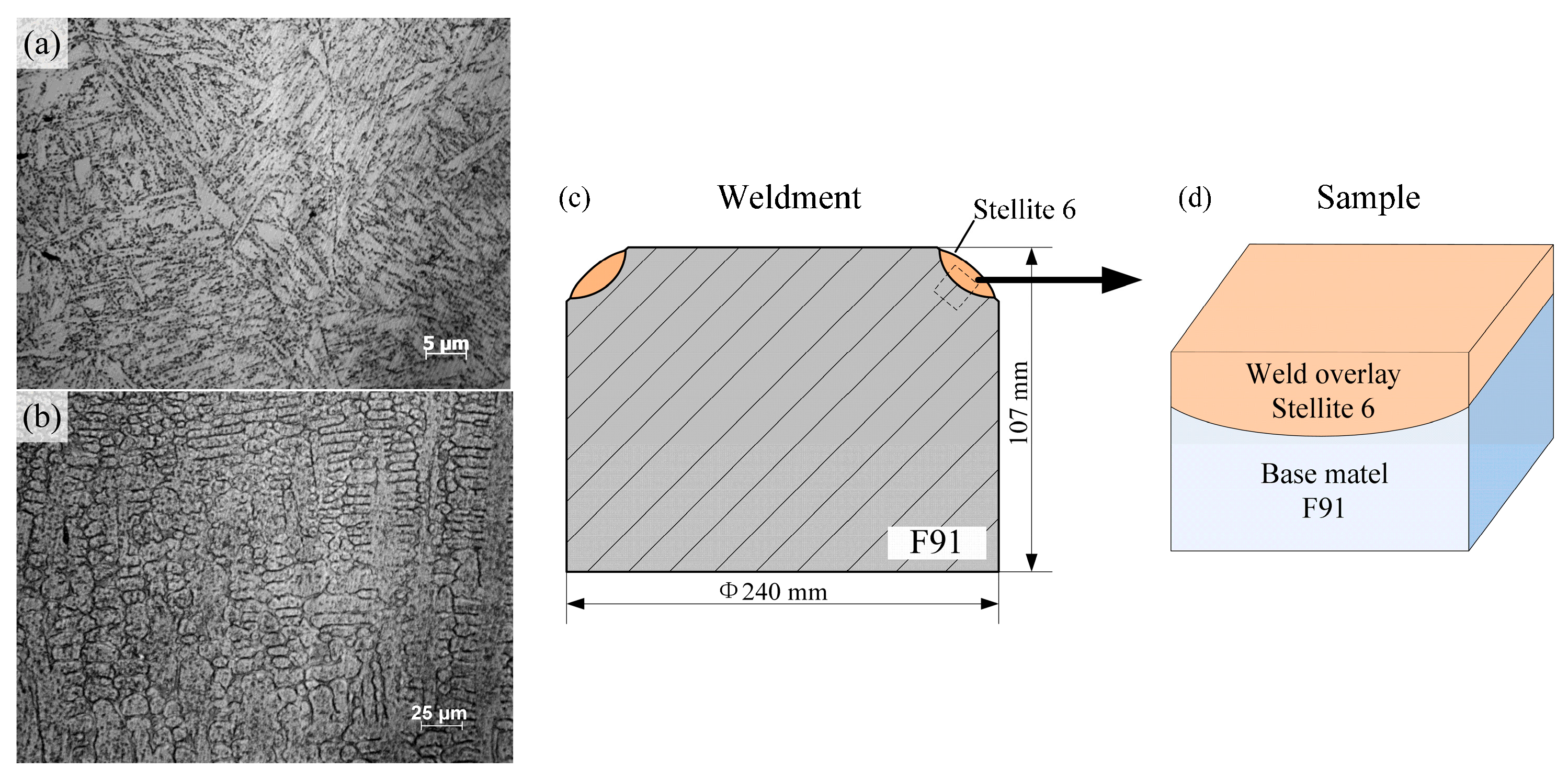
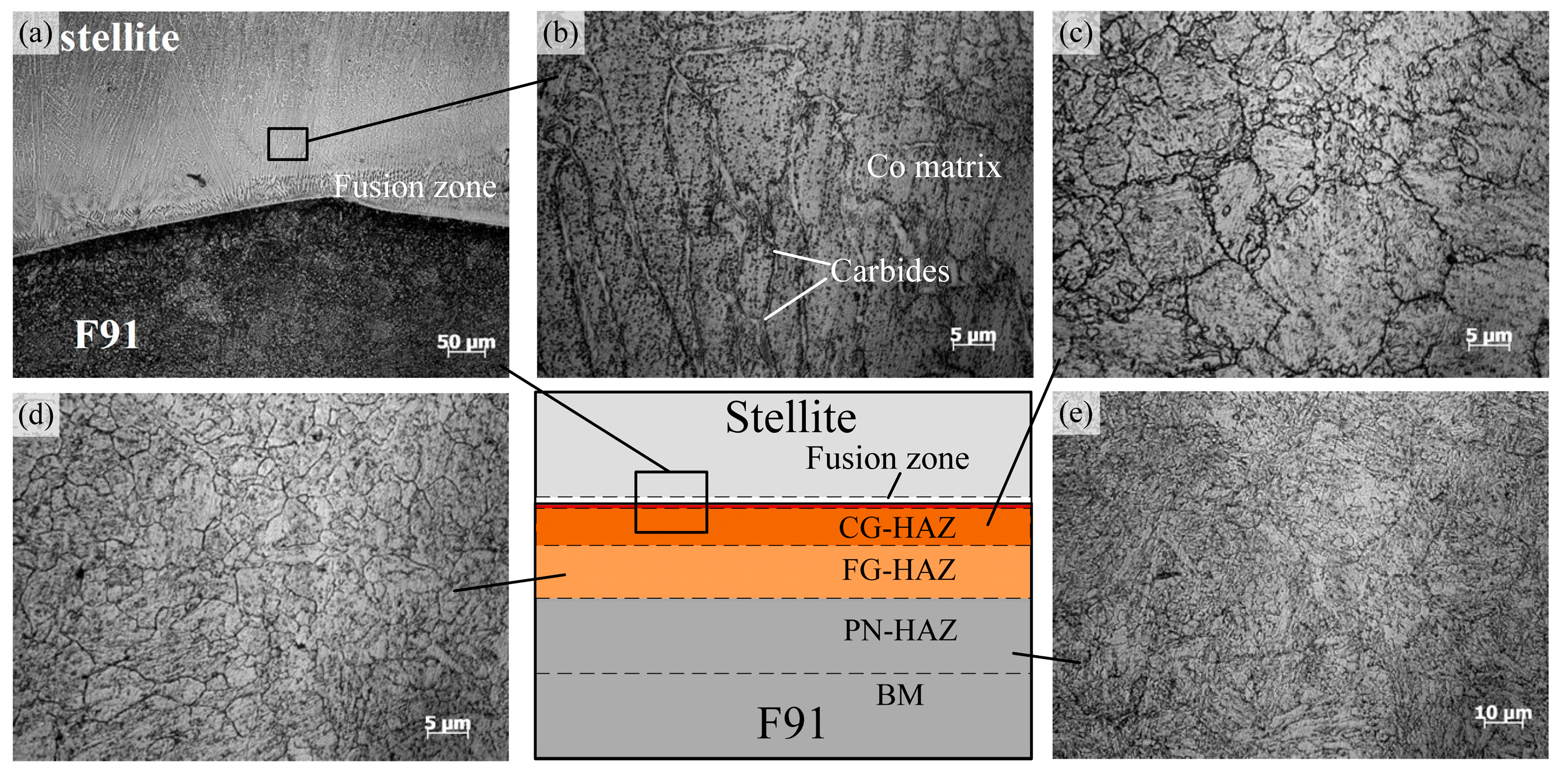
3.1. Microstructure
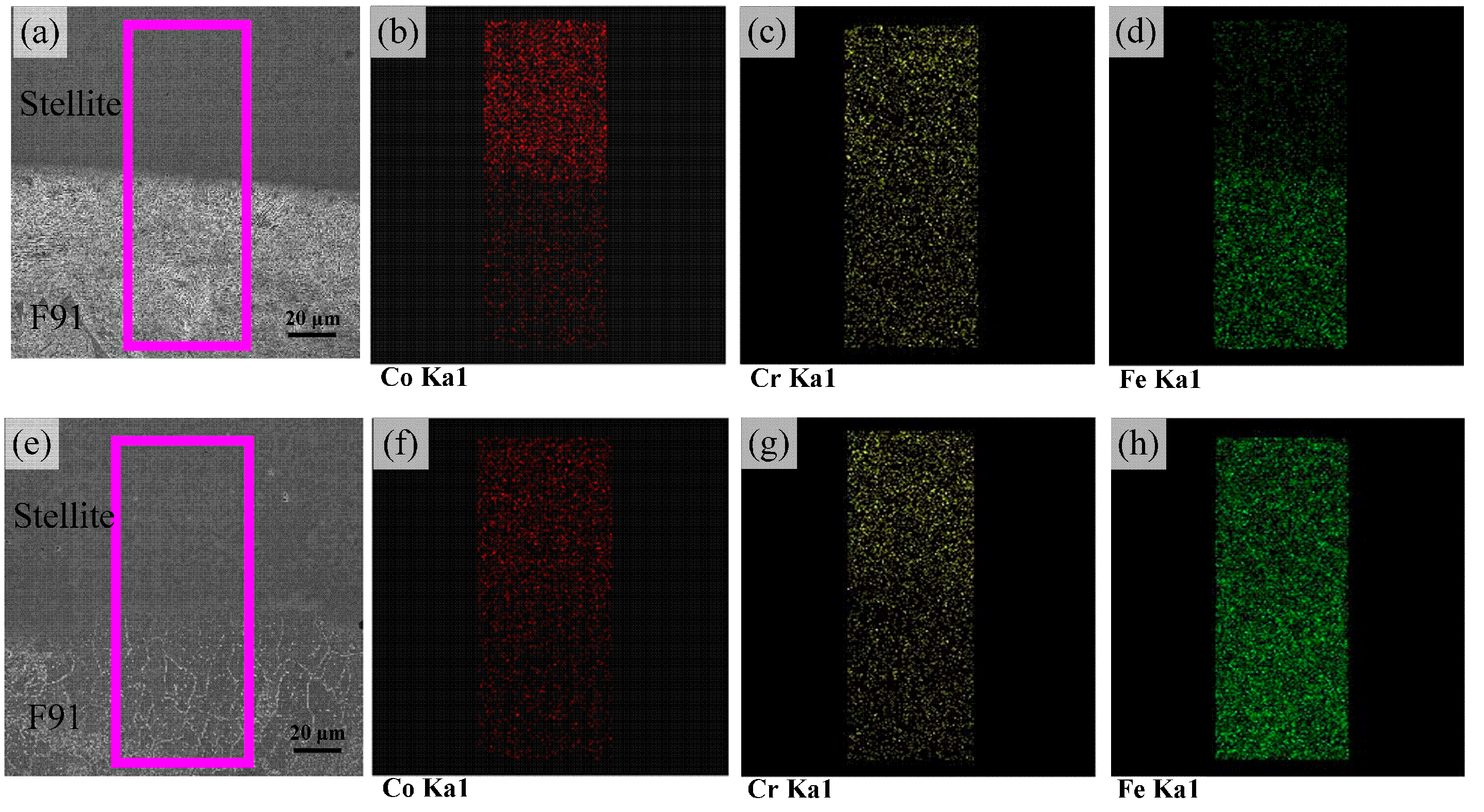
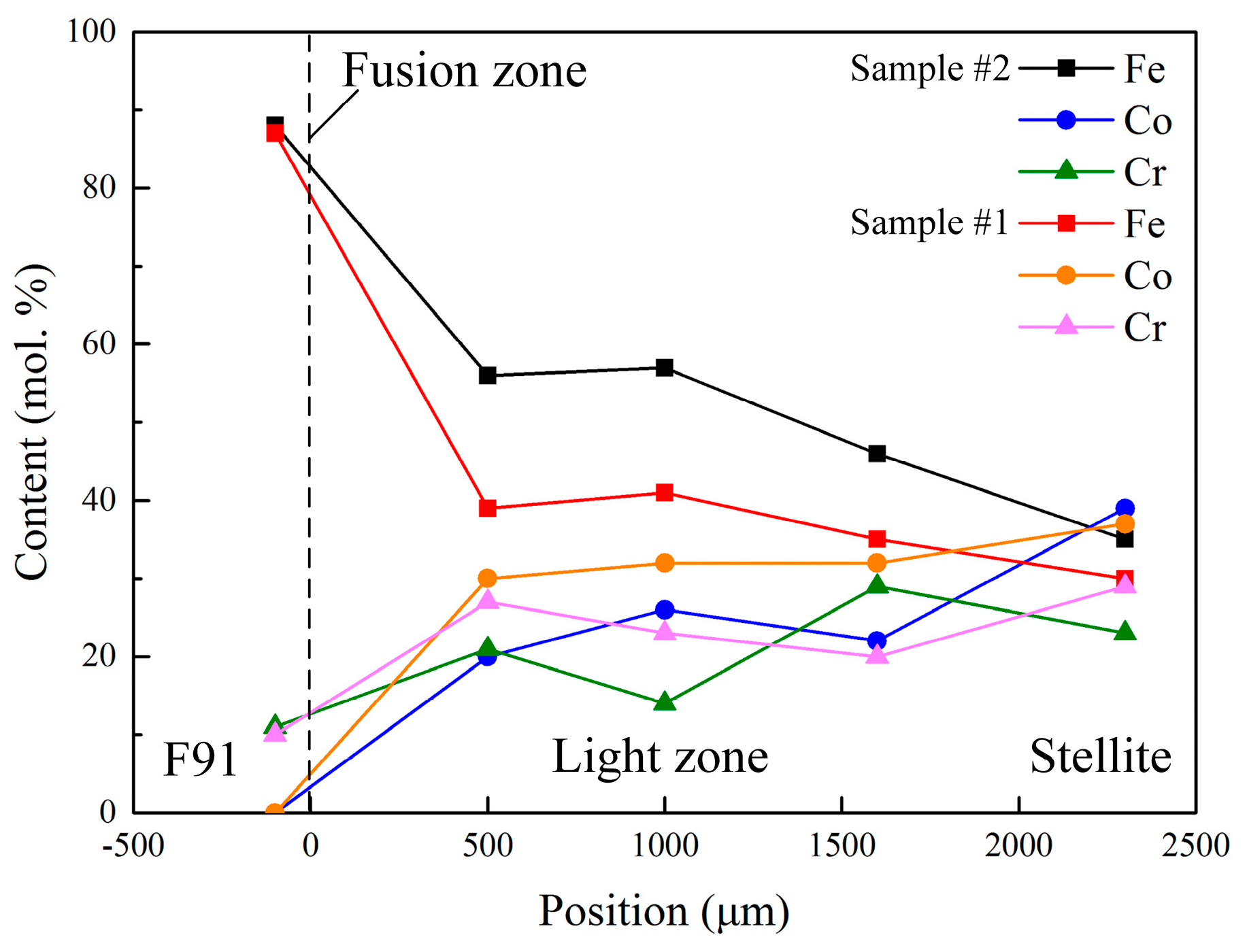
3.2. Distribution of Alloying Elementsand Phases
3.3. Failure Analysis
4. Discussion
5. Conclusions
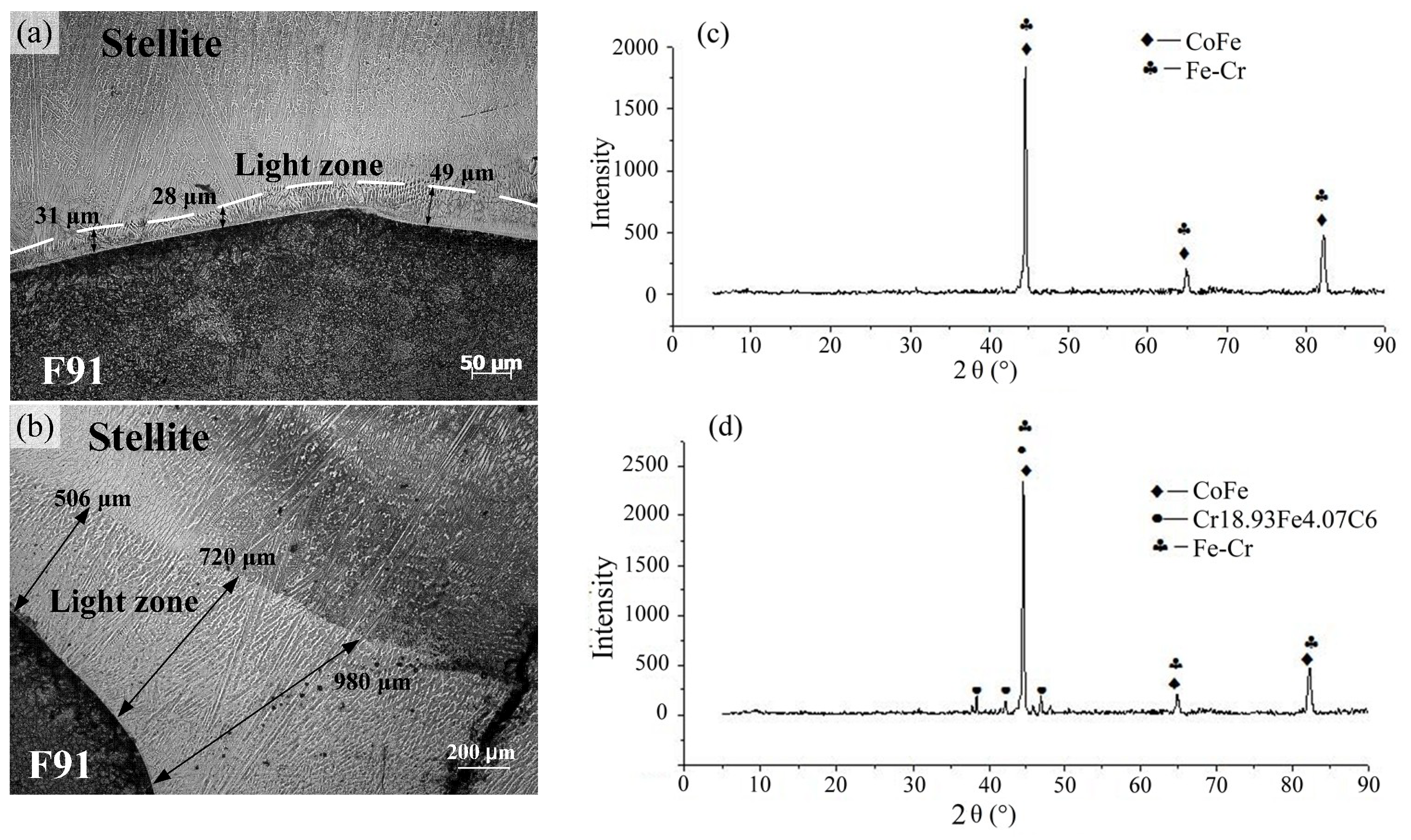
- The microstructure of the Stellite weld overlay near the fusion zone had changed to form a light zone, consisting of Co–Fe substitution solid solutions, σ phases (Fe–Cr metallic compounds) and Cr18.93Fe4.07C6 carbides. The high temperature environment could promote the extent of the light zone. After service, the width of the light zone, combined with fusion zone and diffusion zone, increased significantly to form a large diffusion zone, which could even reach to around 2.5 mm.
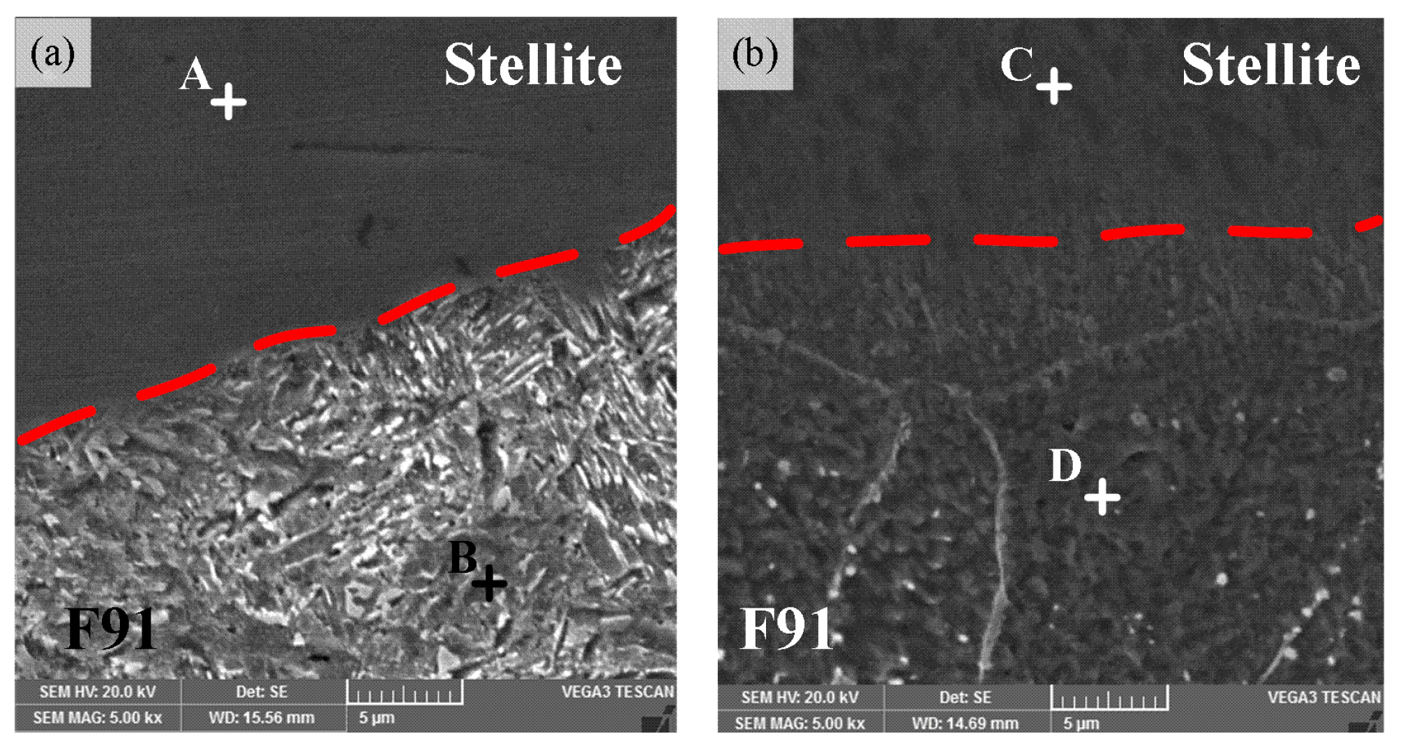
- The obvious diffusion of Fe occurred from the steel and fusion zone to the Stellite overlay, resulting in the microstructure evolution and hardness increase in the weld overlay. The content of Fe increased intensively, but the content of Co decreased, which could eventually lead to the formation of hard and brittle Co–Fe phases.
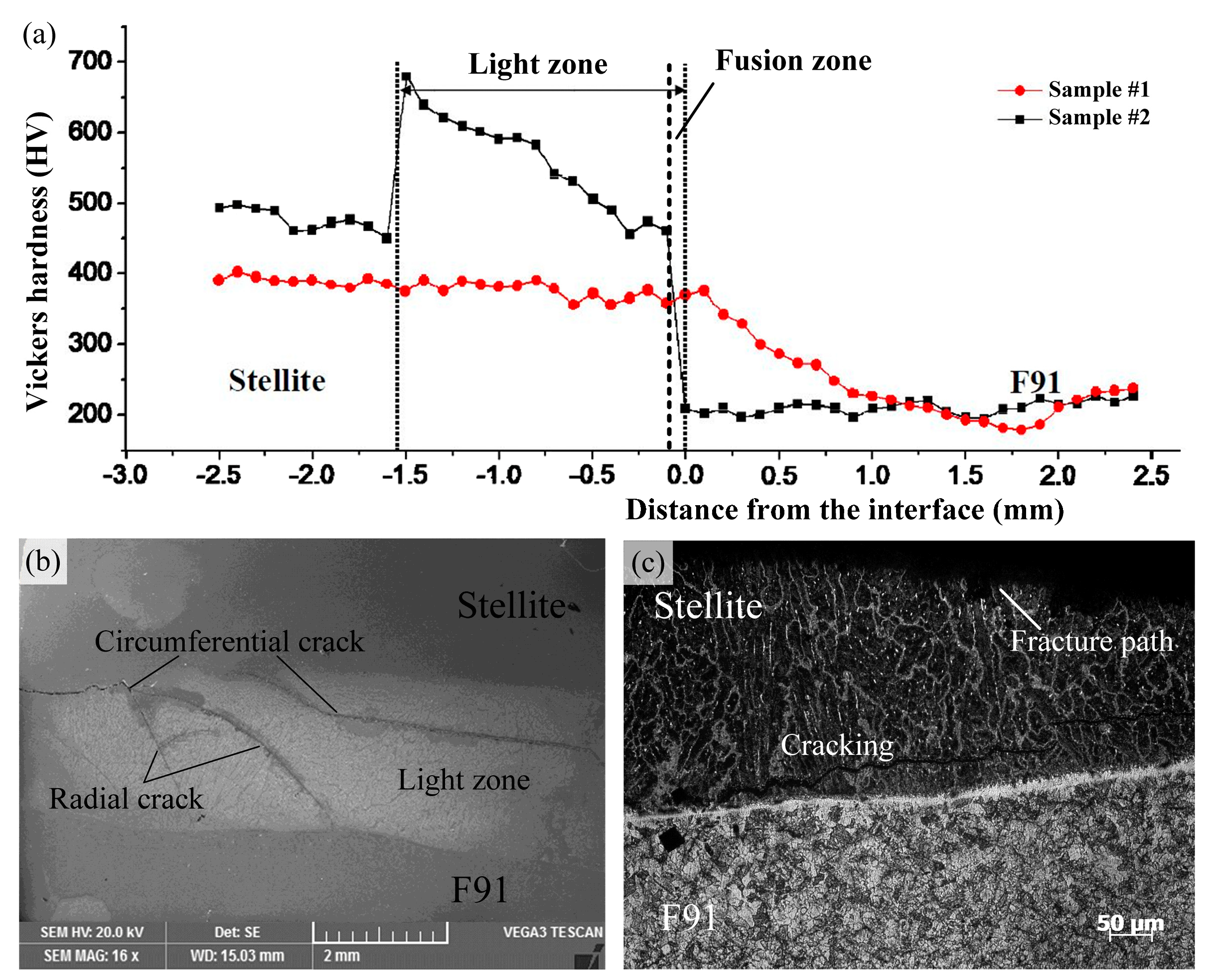
- The micro-hardness in the Stellite weld overlay was higher than that in the steel. After cladding, the micro-hardness in the HAZ increased. After the service process, the micro-hardness values in the Stellite overlay slightly increased to 450–500 HV, while those in the HAZ dropped where the precipitates had coarsened. Moreover, the micro-hardness values in the light zone increased to the maximum (470–680 HV), resulting in changes of micro-hardness between the base material and the Stellite weld overlay.
- The fracture of the Stellite coating samples mainly occurred in the light zone (fusion zone + diffusion zone) after the service process. The formation of these cracks might be caused by formed brittle phases and changes of micro-hardness during service.
Author Contributions
Funding
Acknowledgments
Conflicts of Interest
References
- Fetni, S.; Toumi, A.; Mkaouar, I.; Boubahri, C.; Briki, J. Microstructure evolution and corrosion behaviour of an ASTM A213 T91 tube after long term creep exposure. Eng. Fail. Anal. 2017, 79, 575–591. [Google Scholar] [CrossRef]
- Wang, L.; Li, D.Y. Effects of yttrium on microstructure, mechanical properties andhigh-temperature wear behavior of cast Stellite 6 alloy. Wear 2003, 255, 535–544. [Google Scholar] [CrossRef]
- Falqueto, L.E.; Butkus, D.J.; De Mello, J.D.B.; Bozzi, A.C.; Scandian, C. Sliding wear of cobalt-based alloys used in rolling seamless tubes. Wear 2017, 376–377, 1739–1746. [Google Scholar] [CrossRef]
- Ding, Y.; Liu, R.; Yao, J.; Zhang, Q.; Wang, L. Stellite alloy mixture hardfacing via laser cladding for control valve seat sealing surfaces. Surf. Coat. Technol. 2017, 329, 97–108. [Google Scholar] [CrossRef]
- Yao, J.; Li, Z.; Li, B.; Yang, L. Characteristics and bonding behavior of Stellite 6 alloy coating processed with supersonic laser deposition. J. Alloys Compd. 2016, 661, 526–534. [Google Scholar] [CrossRef]
- Li, B.; Jin, Y.; Yao, J.; Li, Z.; Zhang, Q. Influence of laser irradiation on deposition characteristics of cold sprayed Stellite-6 coatings. Opt. Laser Technol. 2018, 100, 27–39. [Google Scholar] [CrossRef]
- Li, Y.; Zhang, P.; Bai, P.; Su, K.; Su, H. TiBCN-ceramic-reinforced Ti-based coating by laser cladding: Analysis of processing conditions and coating properties. Coatings 2019, 9, 407. [Google Scholar] [CrossRef]
- Tian, L.; Feng, Z.; Xiong, W. Microstructure, micro-hardness, and wear resistance of AlCoCrFeNiTi/Ni60 coating by plasma spraying. Coatings 2018, 8, 112. [Google Scholar] [CrossRef]
- Sawant, M.S.; Jain, N.K. Investigations on wear characteristics of Stellite coating by micro-plasma transferred arc powder deposition process. Wear 2017, 378–379, 155–164. [Google Scholar] [CrossRef]
- Houdková, Š.; Pala, Z.; Smazalová, E.; Vostřák, M.; Česánek, Z. Microstructure and sliding wear properties of HVOF sprayed, laser remelted and laser clad Stellite 6 coatings. Surf. Coat. Technol. 2017, 318, 129–141. [Google Scholar] [CrossRef]
- Sassatelli, P.; Bolelli, G.; Gualtieri, M.L.; Heinonen, E.; Honkanen, M. Properties of HVOF-sprayed Stellite-6 coatings. Surf. Coat. Technol. 2018, 338, 45–62. [Google Scholar] [CrossRef] [Green Version]
- Brownlie, F.; Anene, C.; Hodgkiess, T.; Pearson, A.; Galloway, A.M. Comparison of Hot Wire TIG Stellite 6 weld cladding and lost wax cast Stellite 6 under corrosive wear conditions. Wear 2018, 404–405, 71–81. [Google Scholar] [CrossRef]
- Li, Z.; Cui, Y.; Wang, J.; Liu, C.; Wang, J.; Xu, T.; Lu, T.; Zhang, H.; Lu, J.; Ma, S.; et al. Characterization of microstructure and mechanical properties of Stellite 6 part fabricated by wire arc additive manufacturing. Metals 2019, 9, 474. [Google Scholar] [CrossRef]
- Fang, L.; Yan, H.; Yao, Y.; Zhang, P.; Gao, Q.; Qin, Y. Reactive fabrication and effect of NbC on microstructure and tribological properties of CrS Co-based self-lubricating coatings by laser cladding. Materials 2018, 11, 44. [Google Scholar] [CrossRef] [PubMed]
- Kusmoko, A.; Dunne, D.; Li, H.; Nolan, D. Effect of two different energy inputs for laser cladding of Stellite 6 on P91 and P22 steel substrates. Procedia Mater. Sci. 2014, 6, 26–36. [Google Scholar] [CrossRef]
- Cinca, N.; López, E.; Dosta, S.; Guilemany, J.M. Study of stellite-6 deposition by cold gas spraying. Surf. Coat. Technol. 2013, 232, 891–898. [Google Scholar] [CrossRef]
- Ferozhkhan, M.M.; Duraiselvam, M.; Kumar, K.G.; Ravibharath, R. Plasma transferred arc welding of Stellite 6 alloy on stainless steel for wear resistance. Procedia Technol. 2016, 25, 1305–1311. [Google Scholar] [CrossRef]
- Mirshekari, G.R.; Daee, S.; Bonabi, S.F.; Tavakoli, M.R.; Shafyei, A.; Safaeia, M. Effect of interlayers on the microstructure and wear resistance of Stellite 6 coatings deposited on AISI 420 stainless steel by GTAW technique. Surf. Interfaces 2017, 9, 79–92. [Google Scholar] [CrossRef]
- Molleda, F.; Mora, J.; Molleda, F.J.; Mora, E.; Carrillo, E.; Mellor, B.G. A study of the solid–liquid interface in cobalt base alloy (Stellite) coatings deposited by fusion welding (TIG). Mater. Charact. 2006, 57, 227–231. [Google Scholar] [CrossRef]
- De Mol Van Otterloo, J.L.; De Hosson, J.T.H.M. Microstructural features and mechanical properties of a cobalt-based laser coating. Acta Mater. 1997, 45, 1225–1236. [Google Scholar] [CrossRef]
- Dubiel, S.M.; Zukrowski, J. Fe-rich border and activation energy of phase decomposition in a Fe–Cr alloy. Mater. Chem. Phys. 2013, 141, 18–21. [Google Scholar] [CrossRef]
- Cieslak, J.; Tobola, J.; Dubiel, S.M. Theoretical study of magnetic properties and hyperfine interactions in σ-FeValloys. Intermetallics 2012, 22, 7–12. [Google Scholar] [CrossRef]


| Material | Element (wt %) | ||||||
| C | Cr | Mo | Ni | W | Nb | V | |
| F91 | 0.091 | 9.01 | 0.90 | 0.010 | – | 0.083 | 0.17 |
| Stellite 6 | 0.93 | 27.3 | 0.26 | 1.81 | 3.36 | – | – |
| Material | Element (wt %) | ||||||
| N | Si | Mn | P | S | Co | Fe | |
| F91 | 0.040 | 0.33 | 0.42 | 0.014 | 0.0011 | – | Bal. |
| Stellite 6 | – | 1.08 | 0.13 | 0.014 | 0.0063 | Bal. | 2.17 |
| Position | Element (mol %) | |||
|---|---|---|---|---|
| Fe | Co | Cr | W | |
| A | 46.86 | 28.48 | 20.17 | 4.49 |
| B | 89.13 | 1.32 | 9.55 | – |
| C | 76.69 | 13.21 | 8.08 | 2.02 |
| D | 88.47 | – | 11.53 | – |
© 2019 by the authors. Licensee MDPI, Basel, Switzerland. This article is an open access article distributed under the terms and conditions of the Creative Commons Attribution (CC BY) license (http://creativecommons.org/licenses/by/4.0/).
Share and Cite
Xiong, J.; Nie, F.; Zhao, H.; Zheng, L.; Luo, J.; Yang, L.; Wen, Z. Microstructure Evolution and Failure Behavior of Stellite 6 Coating on Steel after Long-Time Service. Coatings 2019, 9, 532. https://doi.org/10.3390/coatings9090532
Xiong J, Nie F, Zhao H, Zheng L, Luo J, Yang L, Wen Z. Microstructure Evolution and Failure Behavior of Stellite 6 Coating on Steel after Long-Time Service. Coatings. 2019; 9(9):532. https://doi.org/10.3390/coatings9090532
Chicago/Turabian StyleXiong, Jiankun, Fuheng Nie, Haiyan Zhao, Liangliang Zheng, Jun Luo, Lin Yang, and Zhongbo Wen. 2019. "Microstructure Evolution and Failure Behavior of Stellite 6 Coating on Steel after Long-Time Service" Coatings 9, no. 9: 532. https://doi.org/10.3390/coatings9090532
APA StyleXiong, J., Nie, F., Zhao, H., Zheng, L., Luo, J., Yang, L., & Wen, Z. (2019). Microstructure Evolution and Failure Behavior of Stellite 6 Coating on Steel after Long-Time Service. Coatings, 9(9), 532. https://doi.org/10.3390/coatings9090532