1. Introduction
Surface modifications on forming tools and metallic components exposed to tribological environments are widely extended practices in modern manufacturing to enhance their tribological performance. In many industrial processes, tribology plays an important role with regard to process stability and quality [
1]. The wear resulting from the contact between the tool and the workpiece represents a major challenge. In order to increase the service life of tools manufactured using AISI H11, heat treatment and nitriding processes have been the most traditional approaches to reduce wear on the components [
2,
3,
4,
5]. With the introduction and industrial massification of protective nitride coatings, an additional overlay process has been proposed for the wear protection of sliding components. To this end, TiN and CrN are the most commonly employed coating materials due to their relatively high hardness, wear and corrosion resistance. Additionally, with the inclusion of aluminium into the crystallographic structure of the single element nitride, their hardnesses and the resistance to the oxidation have been noticeably increased [
6,
7,
8].
Numerous investigations have dealt with the tribological performance of TiAlN and CrAlN coatings, two of the most promising coatings in diverse industrial applications [
9]. Nevertheless, those results are dependent on the substrate material and properties, the deposition method, the obtained chemical composition, the material of the tribo-partner element and the tribological test parameters [
7,
8,
10,
11]. Most of the investigations of TiAlN and CrAlN coatings are performed using cermets [
12,
13,
14,
15], Ti alloys [
16,
17,
18], high speed steels [
19,
20,
21] or stainless steels [
22] as substrate material. Although the hot work tool steel AISI H11 is widely used in the metal forming industry, only a few studies have investigated the relation between the AISI H11 properties and their direct influence on the performance of the PVD coatings, and much less in ternary transition metal nitrides as TiAlN and CrAlN. For instance, casting dies manufactured of AISI H11 have been coated with PVD coatings such as CrN [
23] and CrAlSiN [
24] in order to increase the lifespan of the tools through the increment of the erosion and corrosion resistance. CrN, TiN and TiN/CrN have been also deposited by Navinsek et al. on industrial tools manufactured by the hot work tool steel AISI H11 in the year 1997, demonstrating at that time the importance of the utilisation of PVD coatings to prolong the life span of metallic tools for diverse applications [
25]. In 2000, Yilbas and Nizam coated nitrided twist drills manufactured with AISI H11 with TiN, improving the adhesion of the coating to the base material. Subsequently, Navinsek used AISI H11 and H13 tools for aluminium die casting, hot extrusion of aluminium and hot forging of steel parts. Industrial tools have exhibited an improved performance when simply coated with a PVD coating (CrN, TiAlN or TiN/TiAlN multilayer) and also when plasma nitrided and subsequently coated [
26,
27]. Moreover, Lugscheider et al. deposited arc ion plating CrAlN onto AISI H11 for semi-solid metal forming applications. Thereby, the coating thickness of the CrAlN coatings was varied in order to modify the residual stresses in the coatings, displaying an increase on compressive residual stresses with increased thickness [
28]. Panjan et al have confirmed an improvement of the wear resistance of hot forging tools manufactured with AISI H11 when the tools are plasma nitrided and are additionally coated with a TiN/TiAlN multilayer coating [
29]. Afterwards, Panjan et al. deposited multilayers of CrN/TiN, Cr/CrN and TiN/TiAlN onto AISI H11 in order to evaluate the crack propagation during the generation of scratch tracks [
30].
Furthermore, a more detailed investigation on the influence of the AISI H11 pre-treatments on the tribo-mechanical performance of nitride coatings was performed by Tillmann et al. [
31,
32,
33]. Sprute et al. have deposited monolayers of TiAlN and multilayers of Ti/TiAlN onto differently prepared AISI H11 and investigated their residual stresses and tribo-mechanical properties. Nonetheless, the pre-treatments proposed by Sprute and Tillmann did not include a thermal treatment of the substrate’s core material and it was limited to a superficial metallographical preparation of the surface using two different grinding materials and to a nitriding process carried out without first hardening the steel [
31]. Based on these results, TiAlN monolayers were deposited onto AISI H11 with four different pre-treatments. Therein, a detailed analysis of the residual stresses depth profiles and hardness depth profiles of the metallic substrates before the deposition was presented, demonstrating the influence of the substrate stresses profiles on the adhesion of the TiAlN coating to the substrate [
32].
The aim of the present investigation is to study the influence of the three different substrate pre-treatments (nitriding, heat treatment and a duplex heat treatment plus nitriding) on the tribo-mechanical performance of the TiAlN/substrate and CrAlN/substrate systems and to create a direct comparison between these two binary coatings when deposited onto an equally treated substrate. Finally, these results are supplementary to previous investigations and will be of great importance for the design and manufacturing of metallic components fabricated with AISI H11 and which require high resistance to abrasive processes such as the development of moulds and dies for the metal forming industry.
2. Materials and Methods
Coin-shaped annealed AISI H11 was used as a substrate material for the deposition of the TiAlN and CrAlN PVD coatings. Before the deposition of the coatings, the steel was subjected to three different pre-treatments as follows: (1) plasma nitriding [Nitr.]; (2) heat treatment [HT] and (3) a combination of the two previous treatments [HT + Nitr.]. These pre-treatments were performed in order to vary substrate properties like roughness, hardness, residual stresses and even the microstructure of their surface.
The plasma nitriding process lasted for 8 h and was performed subsequent to a metallographic preparation of the annealed samples. A controlled atmosphere of 200 Pa with a composition of hydrogen and nitrogen in a 3:1 relation was set. Additionally, a bias voltage of −650 V was applied to attain a temperature of approximately 560 °C, as measured by means of a pyrometer.
Additionally, the pre-treatment herein called HT, consisted of a metallographic preparation of the samples and a subsequent austenitizing, quenching and double tempering. A horizontal high-temperature vacuum furnace manufactured by IVA Schmetz GmbH (Menden, Germany) was utilised for this purpose. Heating rates of 1.5 °C/min were used for all stages of the heat treatment. The austenitizing temperature was 1020 °C, maintained for 20 min followed by a rapid cooling using nitrogen under 1500 mbar of pressure. Double tempering was performed immediately after using the same heating and cooling rates at maximum temperatures of 540 °C with 10 min of holding time. The last pre-treatment consisted of the nitriding of the samples through the previously described heat-treating process, both instances preserving the aforementioned parameters. Due to this, the core material is transformed due to the heat treatment and the most external layer is also hardened due to the nitrogen diffusion.
The deposition of the TiAlN and CrAlN coatings was carried out by means of an industrial magnetron sputtering device (CemeCon CC800/Custom), from the company CemeCon (Würselen, Germany). Preceding the installation of the substrate in the rotating satellites of the deposition chamber, it was cleaned in an ultrasonic ethanol bath. For both coating materials, the entire process consisted of a heating process, plasma etching, metal ion etching and at the end, the deposition of 3 µm of the nitride material. In the case of the TiAlN coating, two targets of TiAl60 (Ti grade 1 plate and 60 plugs with a diameter of 15 mm of Al at 99.5% purity) working at 9.5 kW on DC mode, and one target of Ti grade 1 at 2.0 kW, also on DC mode, were employed. A bias voltage of −100 V and a heating power of 5 kW (425 °C) were applied. Argon and krypton at volumetric flows of 295 and 200 sccm were employed in conjunction with nitrogen as the reactive gas, which was used to keep the pressure in the chamber at 580 mPa. With this configuration, a deposition rate of 24 nm/min was achieved.
In turn, CrAlN coatings were deposited using two AlCr20 targets both of which worked at 5.0 kW on the DC mode. The bias voltage used was −120 V and the heating power was 5.0 kW. Argon and krypton were also employed at different volumetric flows; 120 and 80 sccm respectively. The pressure in the chamber was also controlled by the nitrogen flow at a pressure of 500 mPa and a deposition rate of 8.4 nm/min was achieved.
A scanning electron microscope (SEM, JSM-7001M, JEOL, Tokyo, Japan) was used in order to evaluate the morphology and thickness of the coatings in a brittle cross section fracture. Additionally, the topography of the coatings, the Rockwell C indents, the scratch tracks and the wear tracks were also evaluated using SEM. Besides, the chemical composition of the coatings was evaluated using energy dispersive X-ray spectroscopy (EDX), both including and neglecting the nitrogen content value due to the difficulties in measuring quantitatively light elements by this characterisation technique [
34]. Arithmetic average roughness values of the substrate after the pre-treatment and on the coatings were measured by means of a Nanofocus µsurf white light confocal microscope (Oberhausen, Germany) and the data was analysed using the µsoft analysis software (version 6.2).
X-ray diffraction was used to identify the crystalline phases in the coatings and to calculate the residual stresses. An Advance D8 diffractometer (Bruker, Karlsruhe, Germany) equipped with Fe-Kα radiation was used to generate the diffractograms and with Cr-Kα to calculate the residual stresses. When using Cr-Kα (λ = 2.291 Å), the TiN (111) reflection is located at 2θ = 55.77°, and the CrN (111) reflection at 2θ = 57.24°. Both reflections were used to calculate the residual stresses in the TiAlN and CrAlN coatings. Moreover, hardness and Young’s modulus of the pre-treated steel and the coatings were measured by means of a G200 nanoindenter device (Agilent Technologies, Santa Clara, CA, USA). Depth controlled penetration mode was used at room temperature with a maximum depth of 2 µm. In order to avoid the influence of the substrate’s hardness in the values of the coatings, these results were evaluated between the 10% and 15% of the film thickness [
35,
36]. The Oliver and Pharr method was employed to calculate the hardness and Young’s modulus of the specimens [
37].
The influence of the substrate pre-treatment on the adhesion of the coatings to the treated steel was evaluated by scratch test and Rockwell C adhesion test. A progressive load scratch test was performed according to the norm ASTM C1624 [
38] using a Revetest scratch tester, manufactured by the company CSM Instruments (Peseux, Switzerland). A diamond indenter with a Rockwell C geometry and radius of 200 µm was used. The diamond tip moved along 10 mm increasing the normal force linearly from 0 to 100 N during 60 s. In addition, a Rockwell C adhesion test was carried out according to the VDI guideline 3198 using a normal load of 1 kN. A 971f/3000 universal hardness tester device (Wolpert Wilson Instruments, Norwood, MA, USA) was used for this purpose.
Wear and friction coefficients of the coatings were determined by means of the ball-on-disk test at room temperature using a tribometer (CSM) according to the norm DIN 50324 [
39]. To calculate the wear coefficient, WC-Co balls with diameters of 6 mm and a hardness of approximately 16 GPa were used as a counterpart material during the tribological test [
40]. A normal force of 10 N was applied in a radius of 10 mm for 8000 revolutions at a linear velocity of 0.4 m/s. The wear coefficient was determined through the analysis of the wear volumes with an optical 3D surface analyser (Infinite Focus Alicona, Graz, Austria) that consisted of a confocal microscope connected to suitable image analysis software (IFM version 2.2). Finally, SEM images of the wear tracks and the worn counterparts were analysed in order to obtain information about the wear mechanisms existing in the tribological partners.
3. Results and Discussion
During the presentation of the results obtained in this investigation, a differentiation between the investigations carried out on the steel without the coating, hereby called substrate, and the results obtained from the compounds coating/treated-substrate should be made.
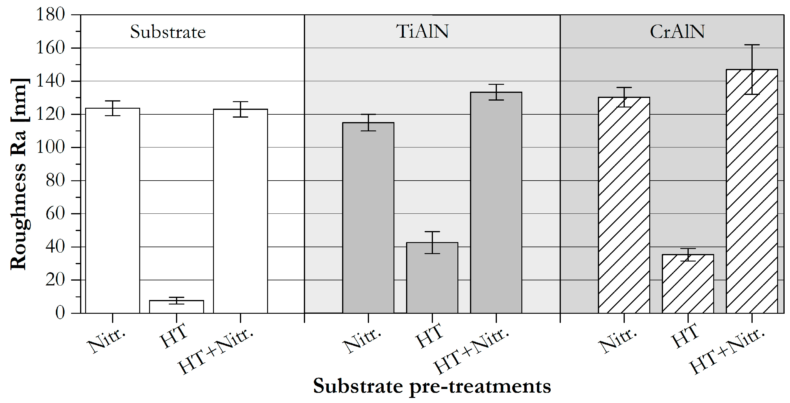
Figure 1 shows a great difference in the roughness values between the nitrided substrates and the heat-treated samples that are not nitrided. During plasma nitriding, the severe sputtering of the surface caused by the nitrogen ions and the applied voltage increases the roughness of the surface, an effect investigated by other authors [
41]. After the deposition of the TiAlN and CrAlN monolayers, the roughness of the coatings presents the same tendency as on the substrates before the deposition. This replicate of the substrate roughness is a typical behaviour observed in the deposition of PVD coatings in addition to an increment on the roughness value after the coating deposition. [
31,
42]. The limited mobility of the adatoms on the rough nitrided surface may generate nucleation sites and shadowing that lead to a rapid build-up of surface roughness. Different behaviour is expected during deposition on substrates with low roughness, where the peaks and valleys of the rough surface are not present and the adatoms generate nucleation points and islands which are more influenced by the energy of the particles than by the surface roughness [
43].
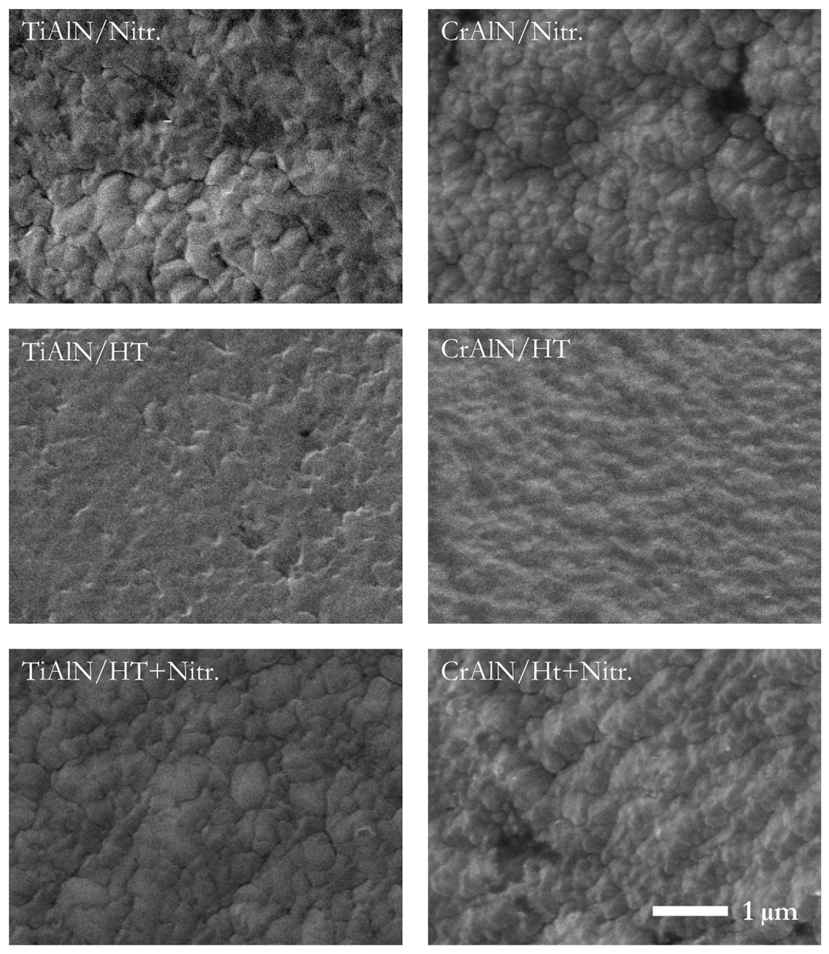
Furthermore, for a qualitative examination of the topography, SEM micrographs were taken on the surface of the deposited coatings (see
Figure 2). Coatings deposited on nitrided substrates have presented a cauliflower-like structure without evidence of major defects. As seen in
Figure 2, both coatings when deposited onto heat-treated substrates exhibited smooth surfaces, a result which is comparable to the obtained roughness values.
Brittle fractures of the cross sections for all the coating/substrate systems were analysed using SEM, the results of which are displayed in
Figure 3. TiAlN coatings deposited onto nitrided substrates (Nitr. and HT + Nitr.) present a slight columnar structure, while the TiAlN on the HT substrate has a denser structure without distinct columns. The size of the columns of the TiAlN coatings on nitrided substrates correlates to the topographical investigation shown in
Figure 1 and
Figure 2. Unlike TiAlN coatings, CrAlN presents a dense featureless microstructure with no growing defects on all the substrates and no differences are evidenced during the SEM analysis of the cross sections.
During the topographical investigation in the SEM, the chemical composition of all the coatings was determined by means of EDX analyses.
Table 1 summarizes the results obtained using this technique. Accordingly, the aluminium fraction in the TiAlN coating is approximately 0.54, from which a cubic face centred NaCl lattice structure can be predicted [
42,
44]. Besides, the CrAlN chemical composition exhibits a higher aluminium fraction, 0.75. According to different authors, this value is within the limit of the aluminium solubility in the c-CrN stable phase, and the presence of some hexagonal phases can be expected [
7,
45]. Ternary nitride coatings may contain different crystalline structures according to the aluminium content; a single cubic phase, mixed cubic and hexagonal phases or a single hexagonal phase [
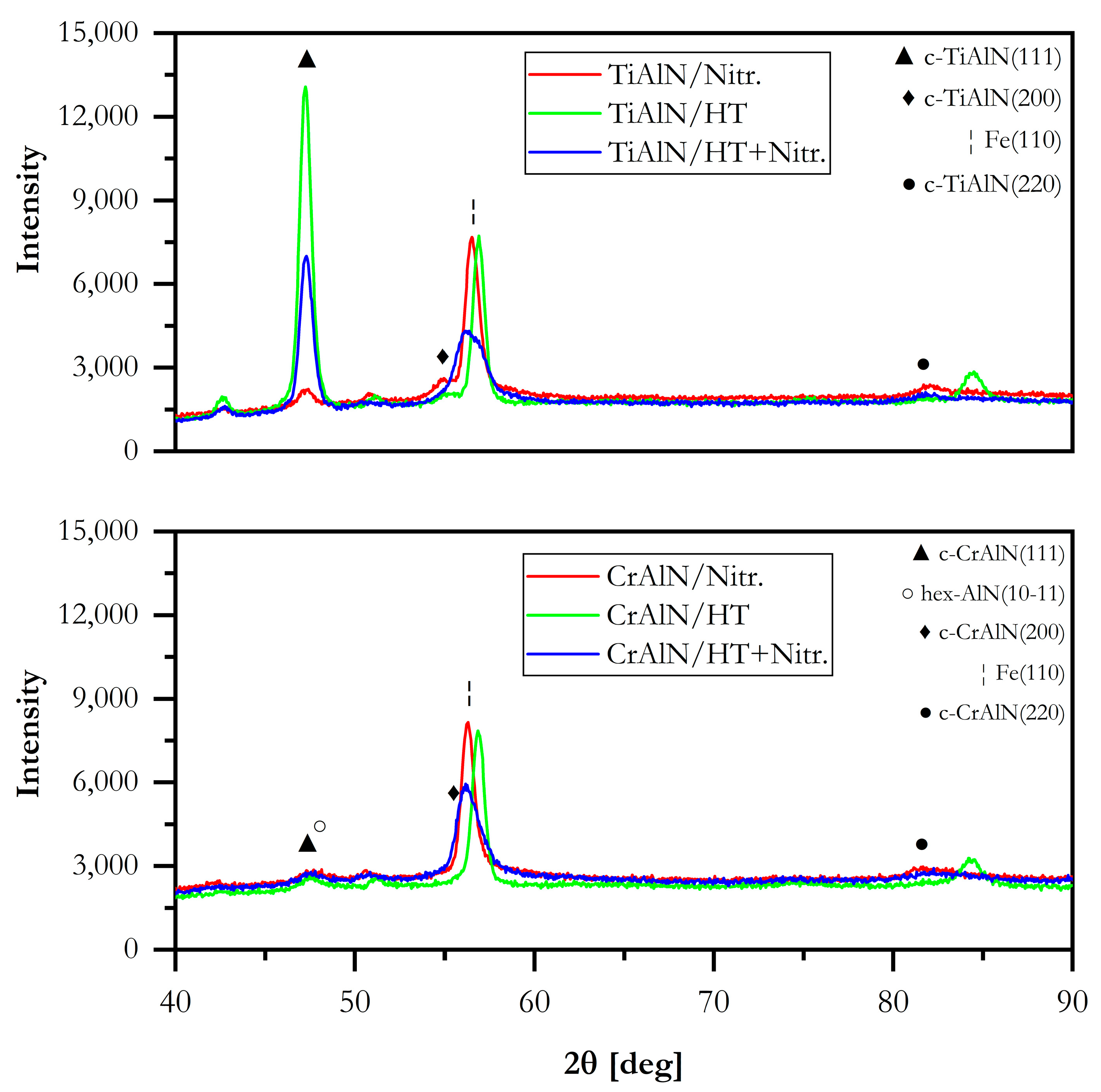
46]. In this investigation, both coatings TiAlN and CrAlN exhibit (111) as the main growth direction when analysed by XRD,
Figure 4. However, the TiAlN coating deposited onto the nitrided substrate presents a low intensity reflection at 2θ = 82.2°, corresponding to the TiAlN (220). In the spectra, low crystallization of the CrAlN coatings can be presumed, and low intensity and broad peaks of the main CrAlN phase are visible.
A high amount of aluminium atoms in the structure hinders the growth of c-CrN phases and promotes the formation of lattice defects reducing the crystallization of the coatings [
47,
48]. When using Fe-Kα, hex-AlN (10–11) possesses a reflection on the 2θ = 48.326°, located in the vicinity of the CrAlN (111) reflection, 2θ = 47.9°, causing an overlapping of the peaks. Therefore, the presence of hex-AlN is not clear in the XRD patterns in
Figure 4. Besides, when observing the TiAlN patterns on different substrates, large differences among them can be noted, what is not the case for CrAlN, wherein the patterns are similar to each other regardless of the substrate used. The TiAlN (111) reflection intensity is higher for those coatings deposited onto heat treated substrate, showing a change in the preferred orientation. In this sense, a high influence of the AISI H11 preparation is evidenced on the structure and crystallinity of the TiAlN coatings while it is not on the CrAlN ones, based in XRD observations. This behaviour is attributed to the differences on nucleation due to epitaxial growth influenced by the substrate structure [
49]. Additionally, the crystallite size of all the coatings was measured according to the Scherrer equation in the reflections TiAlN (111) and CrAlN (111) using Fe-Kα (
Table 2) [
50]. It can be observed that the crystallite size of the CrAlN (111) phase is considerably smaller than those of TiAlN (111), and no significant differences are found from substrate to substrate. Available results of the crystallite size for TiAlN and CrAlN differ among authors [
51,
52]. Nevertheless, the crystallite size values obtained for all the TiAlN coatings are in accordance with the values shown in the review made by Hans et al. for TiAlN with a fraction of aluminium in the range from 0.55 to 0.6 [
51]. Besides, CrAlN crystallite sizes presented here correlate perfectly with those values obtained by Dopita et al. for aluminium ratios of approximately 0.75. As discussed by Dopita et al. the small values in crystallite size are tan evidence of hex-AlN phases in the CrAlN microstructure [
53]. Although there is not a summary of crystallite sizes for CrAlN coatings such as that made by Hans et al. for TiAlN coatings, there can be seen that the lowest crystallite size values belong to hex-TiAlN crystals.
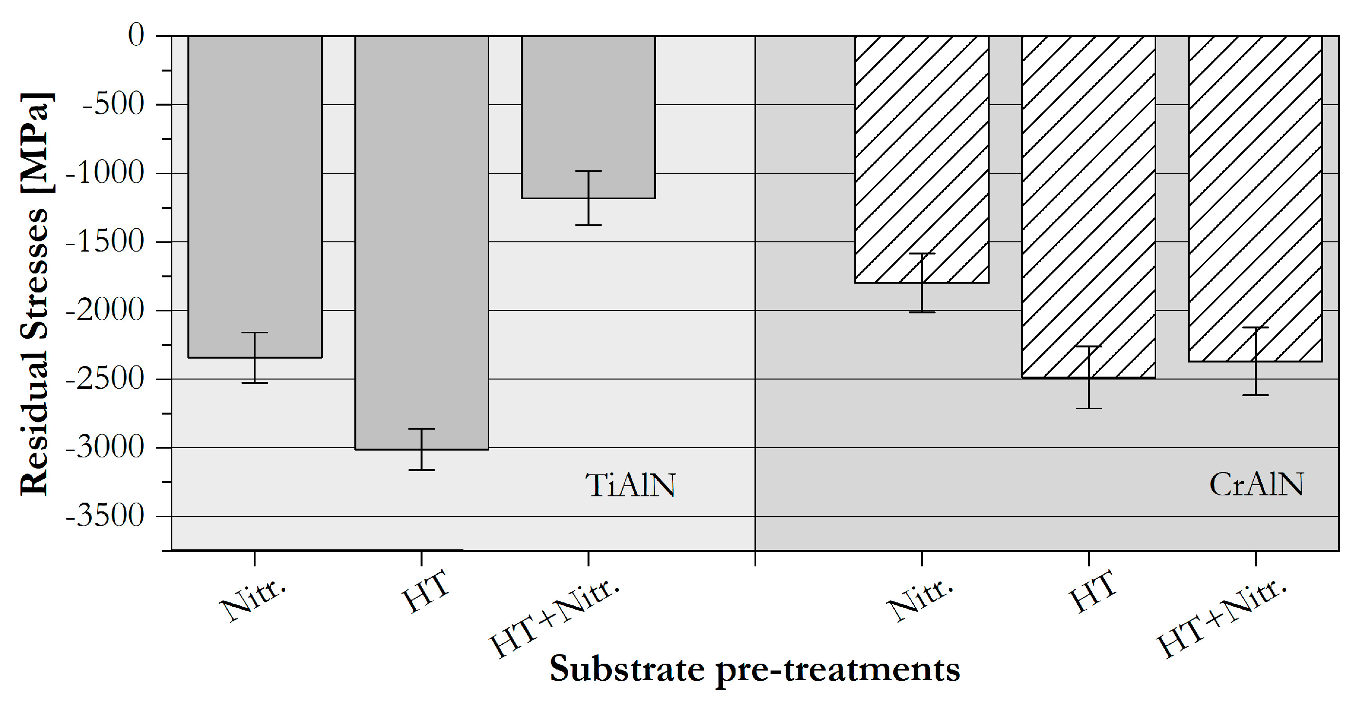
The residual stresses in the coatings were measured using Cr-Kα radiation (see
Figure 5). It is important to clarify that each coating was deposited on all the substrates under the same conditions, and changes on the residual stresses in the coating can be attributed to the properties of the substrate pre-treatment prior to deposition. Both coatings present differences in the residual stresses, depending on the substrate on which they are deposited. In both coatings, the largest compressive residual stress values are obtained for the coatings deposited onto the solely heat-treated substrate, −3012 ± 149 MPa in the TiAlN coatings and −2487 ± 226 MPa for the CrAlN coatings. This behaviour is attributed to the differences of thermal expansion coefficients between the coatings and the heat treated steel [
54].
Hardness and Young’s modulus values of the coatings were calculated,
Figure 6. In general, hardness values of the coatings are always higher than the pre-treated steel used as substrate. Nevertheless, TiAlN coatings are considerably harder than CrAlN coatings in this case. Nitrided substrates and coatings deposited on the nitrided substrates present a high standard deviation due to the high roughness of the surface [
55].
Analysing the hardness values of the TiAlN coatings, it can be noticed that the TiAlN coatings deposited onto the HT substrate possess the highest hardness value, 30.8 ± 3.6 GPa; followed by the coating on the HT+Nitr. substrate, 27.5 ± 5.1 GPa; and finally, the coating on the Nitr. substrate, 23.1 ± 4.9 GPa. Higher hardness of the TiAlN coating on the heat treated substrate can be attributed to the denser microstrucuture of this coating when compared to those deposited onto the nitrided and heat treated plus nitrided substrate. Additionally, higher hardness of the TiAlN coatings was obtained on the coatings with higher compressive residual stresses, a behaviour not found in CrAlN coatings. When compared to current investigations about CrAlN deposited by DCMS, low hardness values of the deposited CrAlN coatings, can be attributed in general to the high fraction of aluminium in the coatings, promoting the formation of low hardness compounds like hex-AlN, as described previously [
56]. Although no significant differences were found between the CrAlN coatings deposited onto the different substrates, the highest average hardness and the broader dispersion of the values was obtained in the coatings deposited onto the HT + Nitr. substrate, 18.8 ± 5.6 GPa. The same trend was evidenced for Young’s modulus, where no big differences are noticeable between the different substrates for both coating materials. The CrAlN coatings present Young’s modulus at about 240 GPa, while TiAlN monolayers present a modulus of around 380 GPa.
Furthermore,
Figure 7 shows the hardness-Young’s modulus ratio, also called the elastic strain to failure ratio (H/E ratio), a typical value used to determine the toughness and resistance to deformation of the materials. The H/E ratios of the coatings are certainly higher than the ratios of the substrates. An important observation on the H/E ratios of the coatings can be made: CrAlN and TiAlN coatings present similar H/E ratio values despite the relatively low hardness of the CrAlN coatings. According to Leyland and Matthews, a high H/E value is an indicator for high wear resistance [
57].
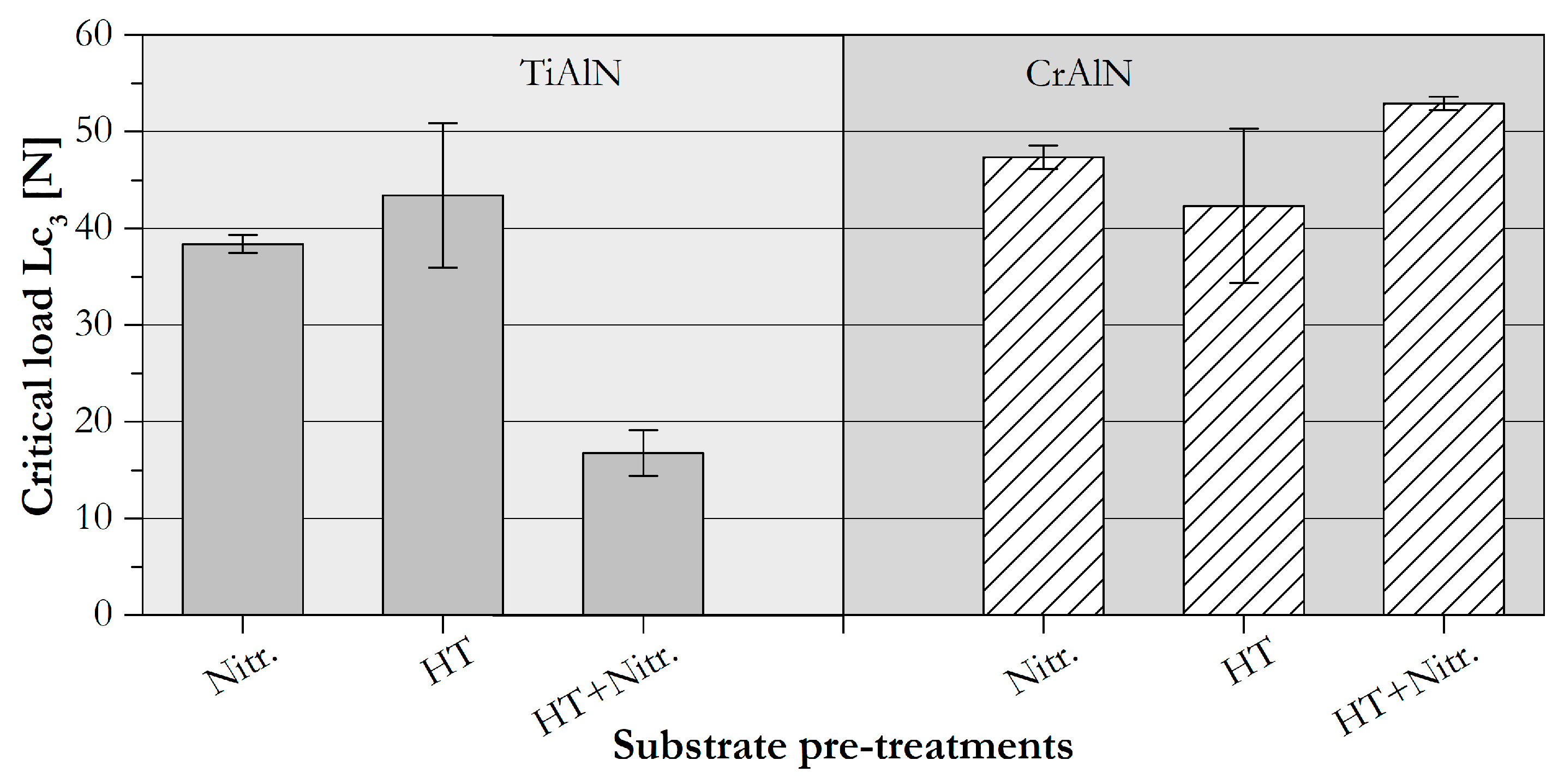
In order to evaluate the adhesion of the monolayers to the different substrates, a scratch test was performed and the critical load 3 (Lc
3) was measured (
Figure 8). It is observed that for TiAlN coatings the lowest critical load was obtained for the coatings deposited onto the HT + Nitr. substrate. As proposed by Bull and Sven et al., high hardness coatings deposited onto brittle substrates, in this case the substrate HT + Nitr., have the higher hardness, present interfacial decohesion if the adhesion is poor, and induce the embrittlement of the layer [
19,
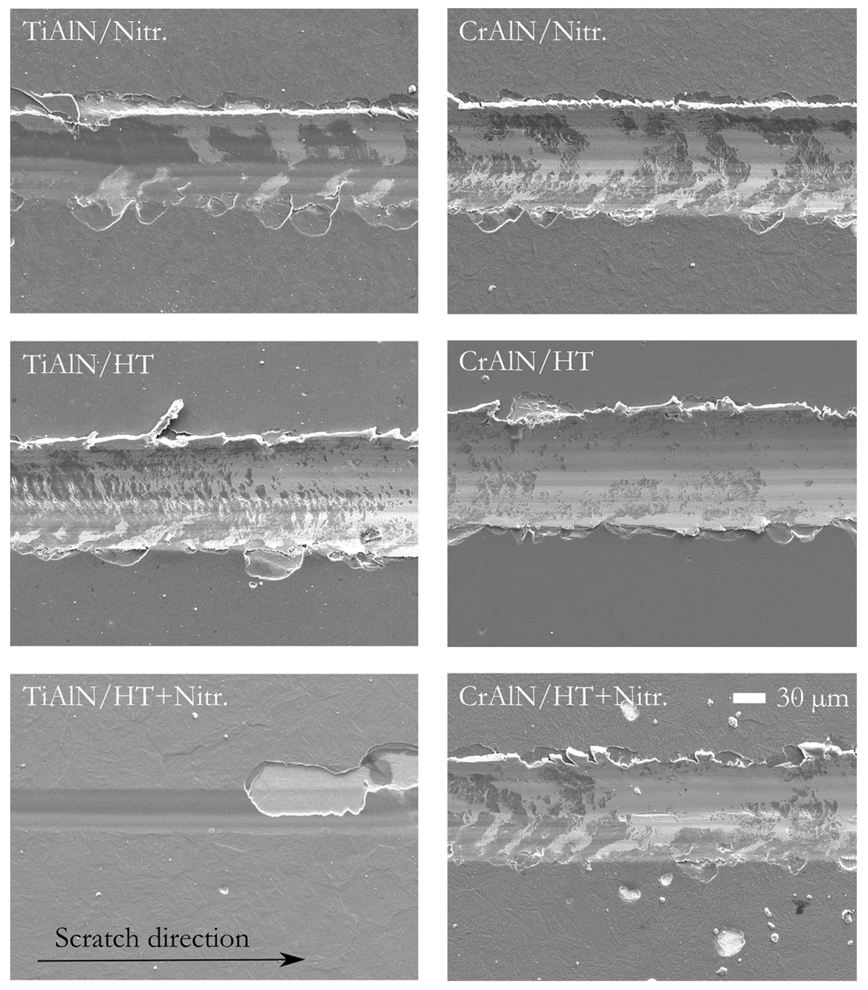
58]. Additionally, throughout the observation of the SEM images in
Figure 9, pure adhesive fracture of the TiAlN on HT + Nitr. substrate is observed without evidence of plastic deformation prior the severe spallation. Correlating the Lc
3 values of the TiAlN coatings with the residual stresses, there is evidence of an improvement of the adhesion of the coating with the increment of residual stresses, opposite to the behaviour found by different authors [
59]. According to Oettel et al., high compressive residual stresses favour the delamination of the coatings [
59]. Skordaris et al. have mentioned the existence of a range where compressive residual stresses are beneficial for the cohesion and adhesion of the material to the substrate; and Ahlgren et al. have also evidenced the presence of a critical compressive residual stresses value were TiAlN starts presenting high delamination [
13,
60]. Thus, the lower limit can be categorised as the approximate −1000 MPa reached in the TiAlN/HT + Nitr. system, and the upper limit where the stresses act in detriment to adhesion, which cannot be identified in this study. The failure mode evidenced on the TiAlN/Nitr. coating can be categorized as recovery spallation [
38,
58]. This behaviour can be explained by the absence of load support in the core of the substrate due to its lower hardness when compared to the nitrided diffusion layer, promoting plastic deformation of the coating together with the substrate. Finally, the highest critical load was found at the TiAlN/HT system. Similar results were found by Huang et al., where the adhesion of TiAlN coatings increases with the reduction of the substrate roughness [
42] and by Skordaris et al. where TiAlN coatings with values between −2000 and −3000 MPa have exhibited a higher adhesion strength to the substrate [
13]. For the TiAlN on the heat treated substrate, the scratch failure mode shows a reduced plastic deformation of the substrate and the coating, without causing delamination of the coating at the edges of the track (
Figure 9).
On the other side and despite their lower hardness values, CrAlN/substrate systems present higher Lc
3 values than their TiAlN counterparts. Unlike the TiAlN coatings, the CrAlN/HT+Nitr. system presented the highest critical load, followed by the CrAlN/Nitr. and the lowest were the CrAlN/HT systems. Higher critical loads are observed on those CrAlN coatings deposited on the nitrided substrates. The higher roughness values evidenced on both of the nitrided substrates (
Figure 1), increase coating-substrate contact area, leading to a greater chemical and mechanical bonding [
31]. Bouzakis et al. have also found an increment on the adhesion of PVD coatings to rougher cemented carbide inserts [
12]. Tillman et al. have found better adhesion of the CrAlN coatings to nitrided AISIM3:2 steel [
61]. Nevertheless, a different behaviour is presented on the TiAlN coatings deposited on the rougher substrate in this research; the higher adhesion of the CrAlN coatings to the metallic substrates can be attributed to the similarity between the Young’s modulus of the substrates and the CrAlN coatings [
57]. Contrary to the TiAlN coatings, all the CrAlN systems present a plastically deformed appearance (
Figure 9). However, through a more detailed inspection, a little spallation is observed on the edges of the grooves created on the CrAlN coatings deposited onto both of the nitrided samples, a similar behaviour to the TiAlN coatings on nitrided substrates.
In order to complement the information about the adhesion obtained by scratch test, the Rockwell C adhesion test was performed on the coating/substrate systems,
Figure 10. The force applied during this experiment is normal to the surface of the coating/substrate system, unlike the scratch test, where shear stress is applied during the linear motion of the stylus [
38,
62].
Figure 10 shows the SEM micrographs taken of the indents after the application of 1 kN Rockwell C indentation on the systems. Additionally, the assessment of the coating failure modes was categorised according to the standards exposed in the guideline VDI 3824-4 [
63], HF1 being the most acceptable adhesion and HF6 the poorest adhesion [
63].
Due to the high forces employed during the Rockwell C characterisation technique, the acting forces present on forming tools are more comparable to this method than on the scratch test. The load support provided by the substrate is crucial for the overall performance of the coating/substrate system. In this sense, coatings deposited on the only nitrided substrates, present craters with large diameters independent of the coating material, TiAlN or CrAlN. The nitriding diffusion zone was not sufficient to withstand the forces and high plastic deformation of the core material is noticeable. Furthermore, the TiAlN/HT system presents the failure mode HF4; delamination at the edges of the indent mark is visible, attributed to the fragility and high hardness and residual stresses of the TiAlN coatings deposited onto this substrate. Besides, the CrAlN/HT system presents fine radial cracks and small spallation at the edge of the indent, fitting into the HF3 failure category. Although the indentation crater is slightly larger, the adhesion of the CrAlN to this substrate is higher than that of the TiAlN, supporting the idea that interfacial adhesion is a coating/substrate property. Nonetheless, CrAlN/HT presents slightly lower compressive residual stresses than the TiAlN/HT coating, promoting the small delamination on the CrAlN/HT system. On the other hand, coatings deposited on the HT + Nitr. substrates have presented HF1 failure mode for both coatings. Radial cracks without delamination of the coatings are observed. The high hardness at the surface of the substrate due to the nitriding process, and in its core material due to the heat treatment carried before nitriding, support the high normal loads applied during this test, thus reducing the buckling of the coatings.
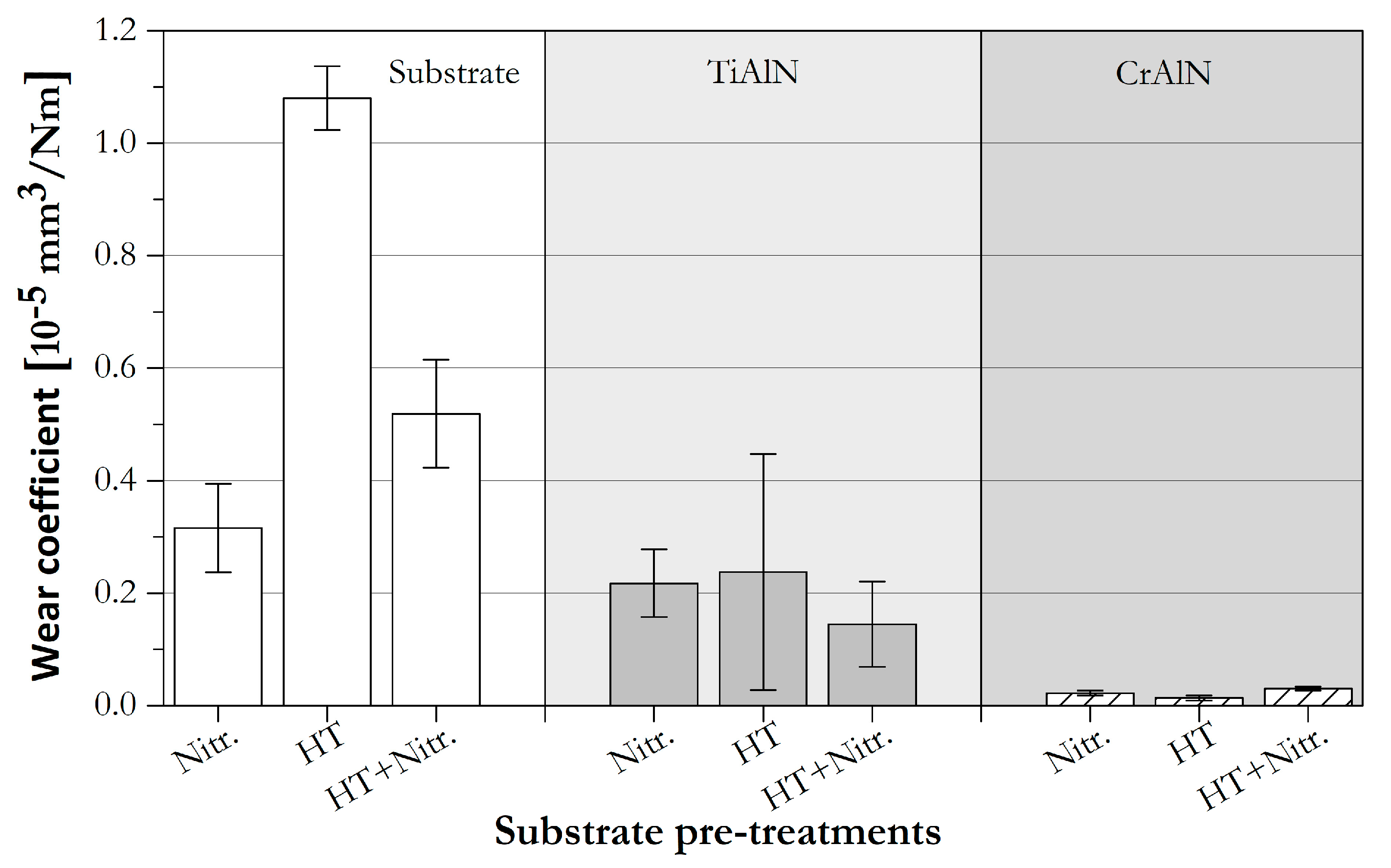
Moreover, and in order to compare the tribological behaviour of the uncoated steel and the coatings, tribological tests were performed to the un-coated substrates and to all the coatings deposited onto the three different substrates (
Figure 11). In general, coated substrates present lower wear coefficients than their respective uncoated counterpart systems, displaying a clear improvement on the wear resistance due to the utilisation of protective coatings. Lower wear coefficients are found for uncoated metallic substrates with higher H/E ratios, in this case, both nitrided substrates. Uncoated nitrided substrates have noticeably improved the wear resistance of the steel subjected to this treatment, as reported by other authors [
2,
4].
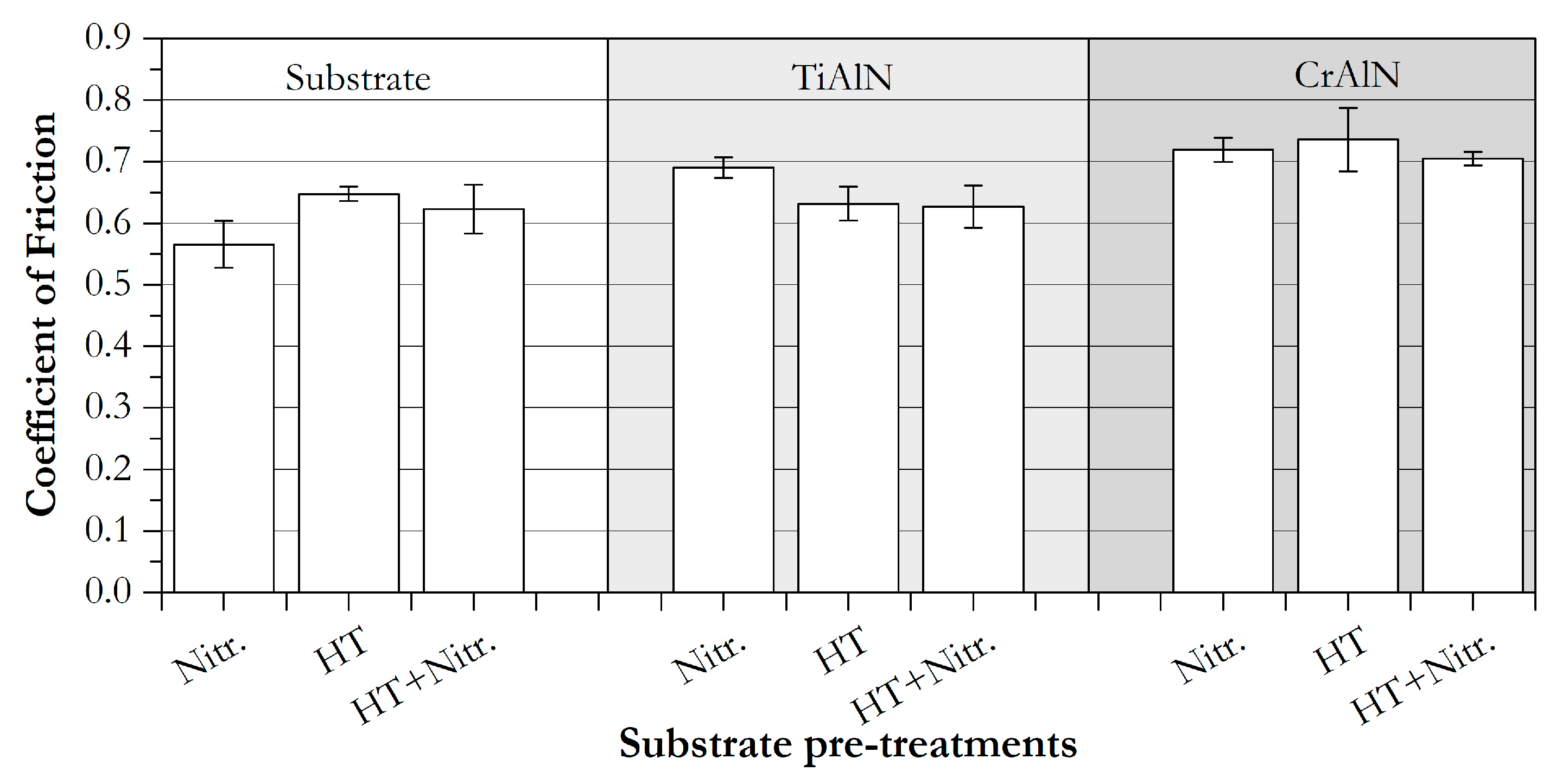
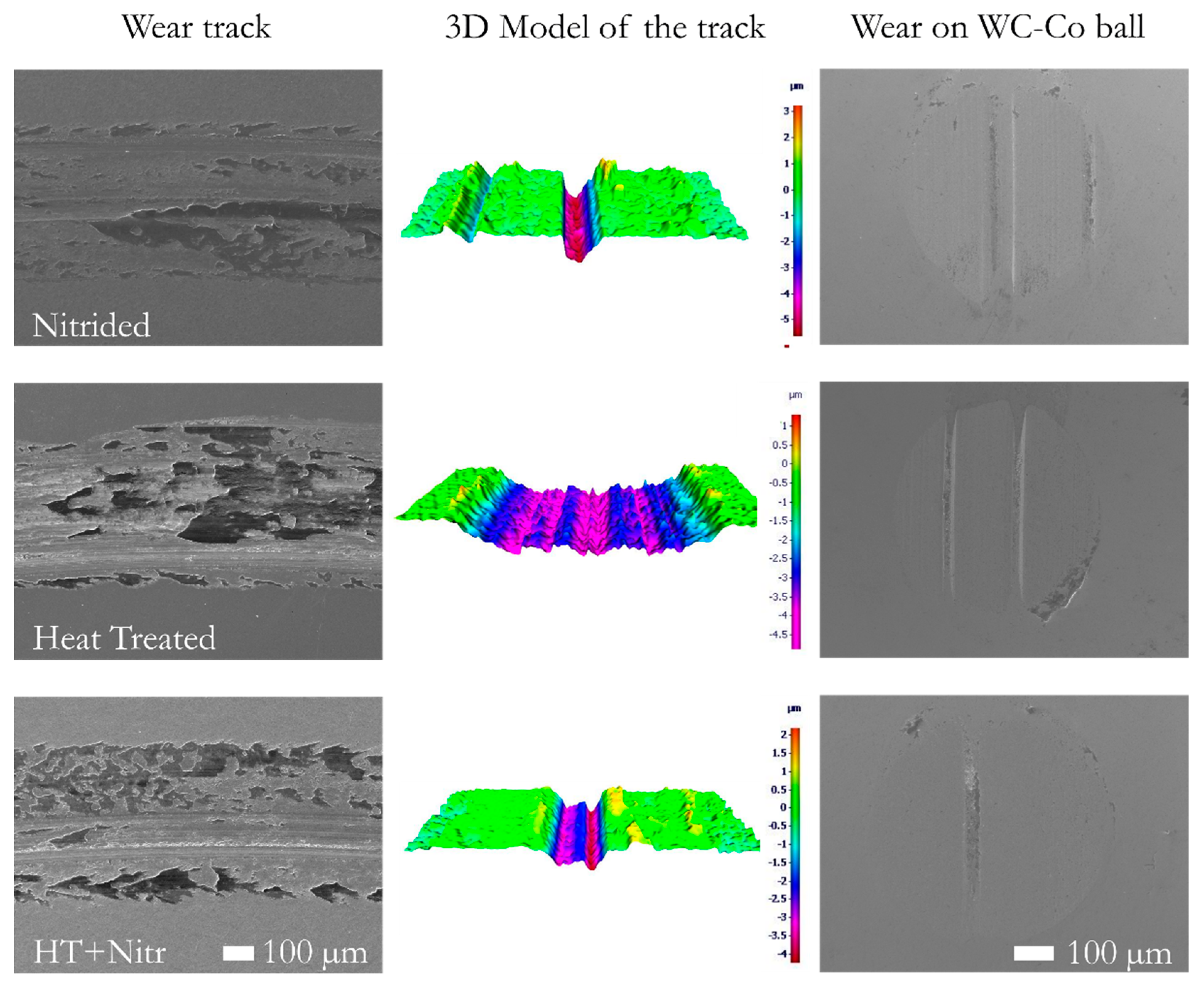
The friction coefficient of the pre-treated substrates, evaluated against an abrasive body of WC-Co, is higher on the just heat-treated steel (
Figure 12). Micrographs of the wear tracks created on the substrates are shown in
Figure 13, together with the 3D model of a characteristic position obtained by optical profilometer. According to the 3D models, the wear track of the heat-treated steel is considerably broader and deeper than those tracks for uncoated nitrided samples. Observing the SEM micrographs of the wear track generated on the heat-treated substrate, the high removal of material is caused by the hard WC particles and adhesive wear together with abrasive wear, due to the formation of oxide abrasive debris on the worn surface. Moreover, uncoated nitrided steel samples present relatively low wear coefficients but a narrow and deep pronounced groove in the direction of the sliding rotation. According to different authors, the presence of the ε-phases in the nitrided AISI H11 improves the wear resistance of the material. However, the presence of abrasive particles, as a product of the compound layer or high hardness nitrides, increase the wear of the samples [
2,
4]. For the TiAlN coatings, the same trend as in the substrates before coating is observed, resulting in higher wear coefficients for the coatings deposited onto the solely heat-treated substrates (HT) (
Figure 11). Hereby, a great influence of the metallic pre-treatment on the wear coefficient of the TiAlN coatings is observed, which is not present in the CrAlN coatings. Regardless, in some of the experiments performed to the TiAlN/HT system samples, the wear coefficient presented higher values than that of the only nitrided metallic substrates without protective coating.
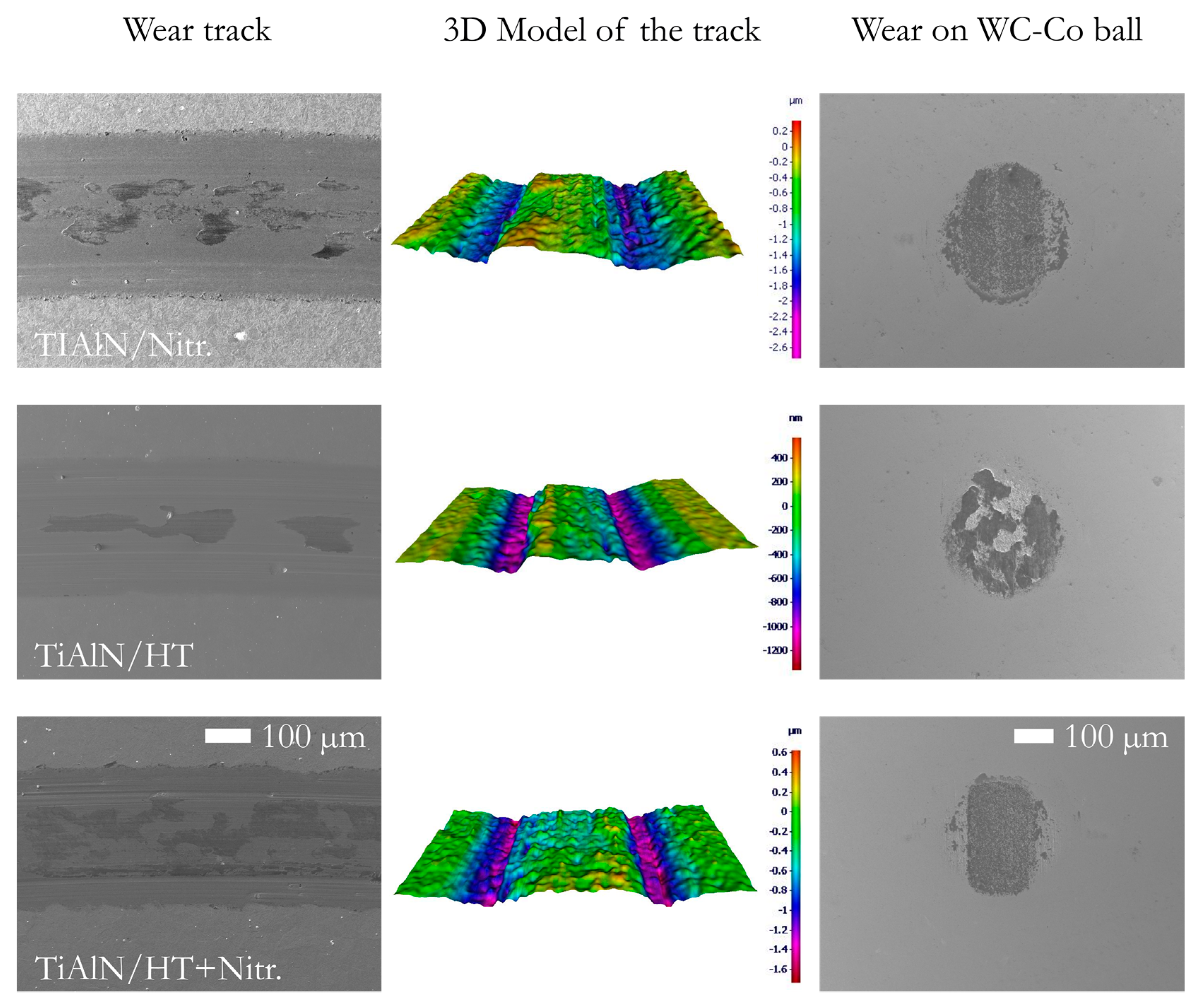
In the 3D models of the wear tracks generated on the TiAlN deposited onto all the substrates (
Figure 14), the formation of deep grooves on the internal and external edges of the tracks can be seen. The reason for these grooves can be the penetration of hard WC particles into the coating, causing the removal of material in the form of micromachining. SEM and EDX analysis performed to the WC-Co tribo-partner balls confirms the presence of coating material adhered to the balls with a high content of oxygen. Therefore, it can be stated that apart from abrasive wear, the TiAlN samples also presented tribo-chemical wear, as a consequence of the increase in the temperature on the contact area during the sliding. Finally, a higher amount of adhered material was detected on the WC-Co balls used in the TiAlN/HT system, proving to be the coating/substrate system with higher wear coefficient among all. At some point, the low roughness of the TiAlN/HT reduces the opposition that the surface applies to the body, increasing the contact time between the counterpart of WC-Co and the surface of the coating. It can be assumed that the prolonged sliding time promotes an increase in the surface temperature, increasing the interfacial bonding of the moving parts [
11]. Finally, a clear relation between the residual stresses in the TiAlN coatings and the wear values can be observed. A high wear coefficient with a high standard deviation can be observed in the TiAlN/HT system. This statement is in agreement with Sokardis et al. and Ahlgren et al. who have established the presence of a point of critical compressive residual stresses, at which point the coating presents a detriment of the tribological performance [
13,
60].
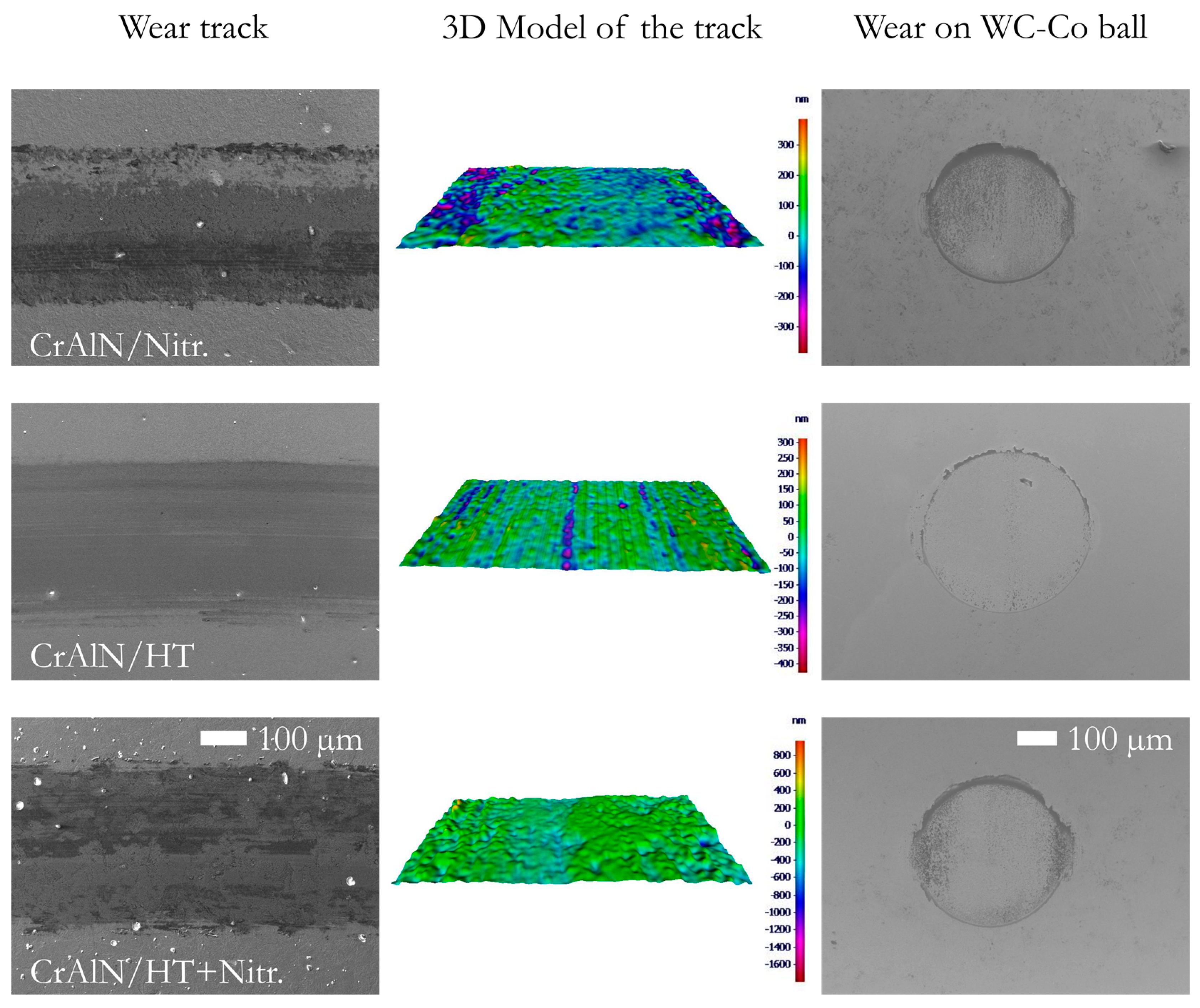
On the other hand, CrAlN/substrate systems have presented significantly lower wear coefficients when compared with TiAlN/substrate compounds and consequently to the substrates without overlay processes (
Figure 11). The wear coefficient obtained using the current tribological conditions was so low that almost no wear tracks are evidenced on the 3D models of the CrAlN coatings (
Figure 15). In addition, the wear track of the CrAlN/HT system presents the smoothest surface after the tribometer test and additionally, the highest abrasive wear on the WC-Co tribo-partner.
CrAlN coatings have exhibited the lowest variation in wear due to the modification of the substrate, unlike TiAlN coatings. The high thermal stability of CrAlN coatings are one of the reasons to explain this outstanding behaviour [
16,
64,
65]. Additionally, as it is known, hexagonal crystals possess better tribological properties than cubic crystals, therefore the assumption of the presence of hex-AlN phases in the CrAlN coatings can also improve the sliding wear resistance when CrAlN is compared to the TiAlN coatings [
66]. Additionally, CrAlN coatings deposited here have presented low hardness and high H/E ratios, increasing their resistance to fatigue as originated during tribological tests. These results are in agreement to the results obtained by Aihua et al. [
11], where CrAlN coatings have presented lower wear rates than TiAlN coatings with high amount of aluminium.


