Article

Microstructure and Properties of CrAlSiN Coatings Deposited by HiPIMS and Direct-Current Magnetron Sputtering

1
Tianjin Key Laboratory of High Speed Cutting and Precision Machining, Tianjin University of Technology and Education, Tianjin 300222, China
2
National-Local Joint Engineering Laboratory of Intelligent Manufacturing Oriented Automobile Die & Mould, Tianjin University of Technology and Education, Tianjin 300222, China
*
Authors to whom correspondence should be addressed.
Coatings 2019, 9(8), 512; https://doi.org/10.3390/coatings9080512
Submission received: 9 July 2019 / Revised: 6 August 2019 / Accepted: 9 August 2019 / Published: 13 August 2019

Abstract

:
Four CrAlSiN coatings with different Al contents were prepared by varying Al sputtering power using a combined method of high power impulse magnetron sputtering (HiPIMS) and direct current magnetron sputtering (DCMS). Microstructure, chemical compositions and mechanical properties of the four coatings were characterized by XRD, XPS, SEM, TEM, nano-indentation etc. Results showed that the four coatings possessed face-centered cubic (fcc) CrN phase with Al and part of Si dissolved in it. Another part of Si existed as amorphous phase in the coatings. All the four coatings had columnar structure and formed in epitaxy growth by template effect. With increasing Al sputtering power, the Al content increased from 11.4 to 17.6 at.% gradually, while the Cr content decreased a little. The hardness of the CrAlSiN coatings increased initially probably due to the refinement of the coating grain size, while it decreased afterwards mainly caused by the aggregation of small particles leading to rougher surface and defects formed in the coatings. The elastic modulus and adhesive strength possessed the same variation tendency as the hardness versus Al sputtering power. The CrAlSiN coating with Al sputtering power of about 0.8 kW had the highest hardness of about 26.7 GPa and adhesive strength of about 27.2 N.

1. Introduction

Binary coatings like CrN, TiN have been applied in industries such as molding dies, wear components and cutting tools for the past decades, due to their high hardness and good wear resistance [1,2,3]. However, with the development of manufacturing technology, more difficult-to-machine materials need to be machined, and better surface finish as well as higher cutting tool life are required, so researchers attempt to enhance the coatings’ properties continuously. Multicomponent coating that takes advantage of individual components is one of the effective ways to obtain superior comprehensive properties. Research shows that multicomponent coating e.g., CrAlSiN, TiAlSiN and CrAlSiWN possesses good mechanical properties, oxidation resistance and cutting properties [4,5,6].
The quaternary CrAlSiN coating consists of nano-crystalline (Cr,Al)N and an amorphous nitride silicon phase. It is reported to possess super hardness attributing to two aspects: on one hand, the element Al could be dissolved in CrN lattice space substituting for the Cr sites and plays as a barrier to dislocation propagation [7]; on the other hand, Si tends to segregate along the grain boundaries as amorphous SixNy leading to grain boundary hardening and crystal size refinement since it could hinder the growth of the fcc-(Cr,Al)N phase [8]. In addition, a mixed protective oxide layer primarily composed of stable α-Al2O3 could be formed on the surface of the coating at high temperature or in a corrosive environment which makes the coating possess good oxidation resistance and chemical stability. Thus, the CrAlSiN coating is appropriate for applications at high temperature such as metal forming or dry high-speed cutting process [9]. To obtain CrAlSiN coating with optimal properties, researchers have tried different coating technologies and studied the influence of various deposition parameters such as depositing temperature, bias voltage etc. on the microstructure and properties of the coating [1,10]. However, reports about the effect of Al content on the microstructure and mechanical properties of the CrAlSiN coating are still limited.
Chemical vapor deposition (CVD) was widely used for its high deposition rate. However, there are harmful by-products generated, and the deposition temperature is high which would deteriorate the properties of the substrate. Physical vapor deposition (PVD) which is free of these two disadvantages meets the requirement of green manufacturing, and has been getting more and more attention. Among all the PVD methods, high power impulse magnetron sputtering (HiPIMS) is an enhanced technology for traditional magnetron sputtering by the addition of pulsed power [11]. It possesses a high degree of ionization of the sputtered atoms and high target peak currents, which is beneficial for depositing coatings with a dense and smooth structure [12,13]. However, the deposition rate of the HiPIMS technology is low, which limits its application [14]. One way to solve this problem is developing a hybrid process with another coating technology. Direct current magnetron sputtering (DCMS) is commonly used in preparing coatings with a fine structure and reported to possess a higher deposition rate than the HiPIMS technology. Thus, a combined method of HiPIMS and DCMS was used to deposit four nano-composite CrAlSiN coatings using different Al sputtering power in this paper. The microstructure, chemical compositions and mechanical properties of the coatings were investigated to figure out the effect of Al sputtering power on the microstructure and properties of the CrAlSiN coatings.

2. Materials and Methods

Four CrAlSiN coatings with different Al content were deposited by a combined method of high power impulse magnetron sputtering (HiPIMS) and direct current (DC) magnetron sputtering. The elements Cr (99.99 wt.%), Al (99.99 wt.%) and Si (99.999 wt.%) were used as targets. The Cr target was powered by HiPIMS, while the Al and Si targets were driven by DC magnetron sputtering. The three targets were distributed evenly on the columnar vacuum chamber wall with the same installation height. YG8 cemented carbides and (111) single crystalline Si wafers were used as substrates. They were cleaned using ultrasonic cleaning machine in acetone and alcohol for 15 min successively. Afterwards, they were dried and fixed on a substrate holder in the chamber furnace. The substrate holder rotated at a speed of 30 r/min and was parallel to each target intermittently in one rotation period. When it faced directly to the target, the distance between them was about 70 mm. The chamber furnace was evacuated to less than 1.0 × 10⁻³ Pa by mechanical pump and molecular pump, and then heated to 300 °C. Once the chamber pressure was lower than 1.0 × 10⁻³ Pa again, Ar was let into the chamber until the chamber pressure was up to 1 Pa. In order to remove the contaminations on the substrate surface, the samples were bombarded by Ar ion under −800 V negative bias voltage for 20 min. Afterwards, the Cr, Al, Si targets were powered on, and the bias voltage decreased to −600, −400, −200 V gradually at the interval of 2 min. Then the Al and Si targets were powered off, and the bias voltage was set as −30 V to deposit a Cr interlayer for improving the adhesive strength between the coating and substrate. After 30 min, the Al and Si targets were electrified again and N2 was transported into the chamber to deposit the CrAlSiN coating. For the four different CrAlSiN coatings, the target powers of Cr and Si were fixed at 1.0 and 0.6 kW separately, while the Al target power was chosen as 0.6, 0.8, 1.0 and 1.2 kW respectively. The detailed deposition parameters of the four CrAlSiN coatings are presented in Table 1.
Phase structures of the four CrAlSiN coatings were characterized by using X-ray diffraction (XRD, X’Pert PRO, Panalytical, The Netherlands). To avoid the (111) diffraction peak of the silicon wafer, the glancing scanning method was applied to detect the phase structures of the coatings. The surface and cross-sectional morphologies of the coatings were observed by a field emission scanning electron microscope (SEM, ZIESS, Oberkochen, Germany), and the chemical compositions of the coatings were analyzed by an electron-dispersive X-ray spectrometer (EDS, Oxford, Oxfordshire, UK). High resolution transmission electron microscope (TEM, Talos F2000, FEI, Morristown, NJ, USA) was used to investigate the cross-sectional morphologies of the coating. The surface roughness of the coatings was measured by a surface profilometer (Alpha Step D-300, KLA Tencor, Ballston Spa, NY, USA).
The hardness and elastic modulus of the four CrAlSiN coatings were measured by using a nano-indenter tester (MTH, CSM, Peuseux, Switzerland) with a diamond tip indenter. The maximum indenter load was chosen as 10 mN under a dwelling time of 5 s. Five measurements were taken on each sample to obtain an average value. The adhesive strength between the CrAlSiN coatings and substrate (YG8 cemented carbide) was measured by a scratch tester (RST, CSM, Peuseux, Switzerland). The scratch length was chosen as 3 mm, and the normal load increased from 1 to 50 N with a loading rate of 0.98 N/s.

3. Results and Discussion

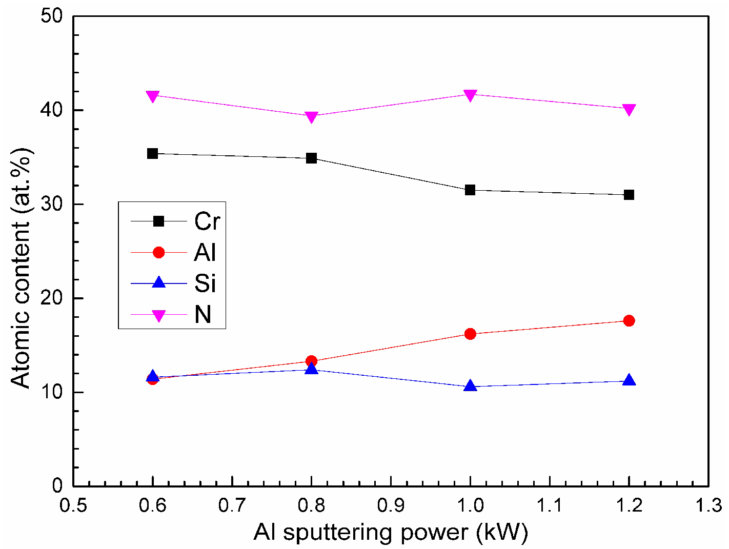
3.1. Composition and Phase Characterization
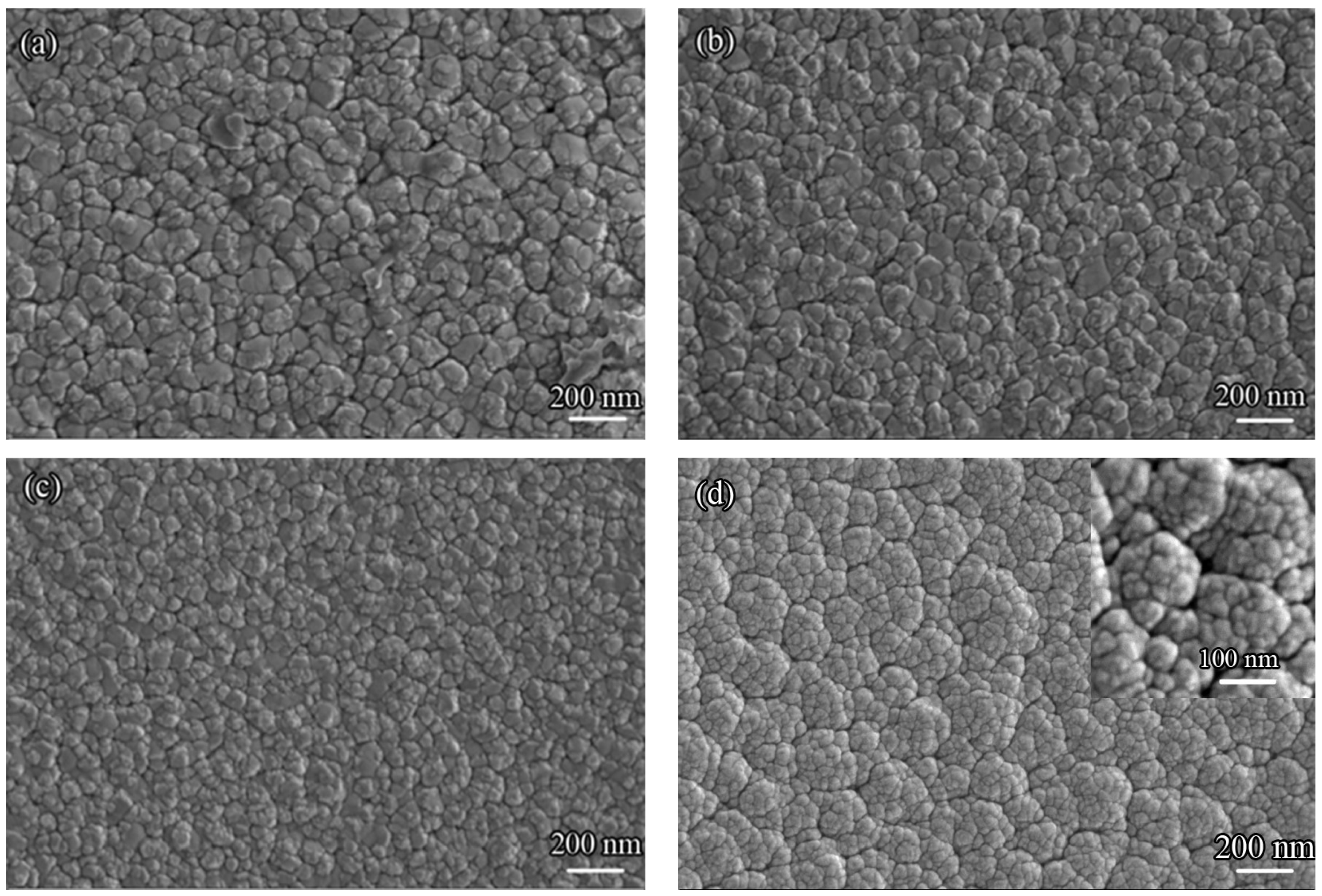
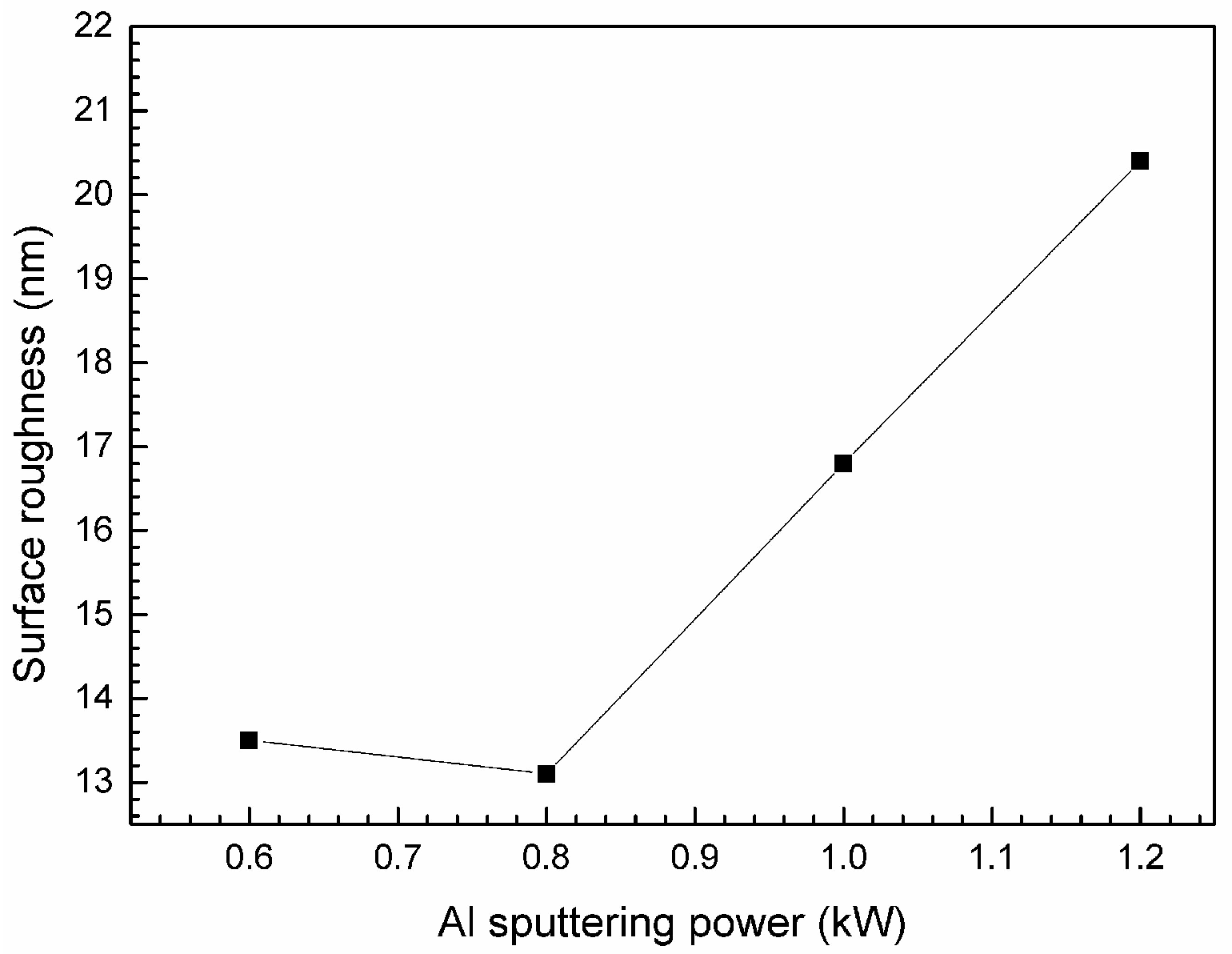
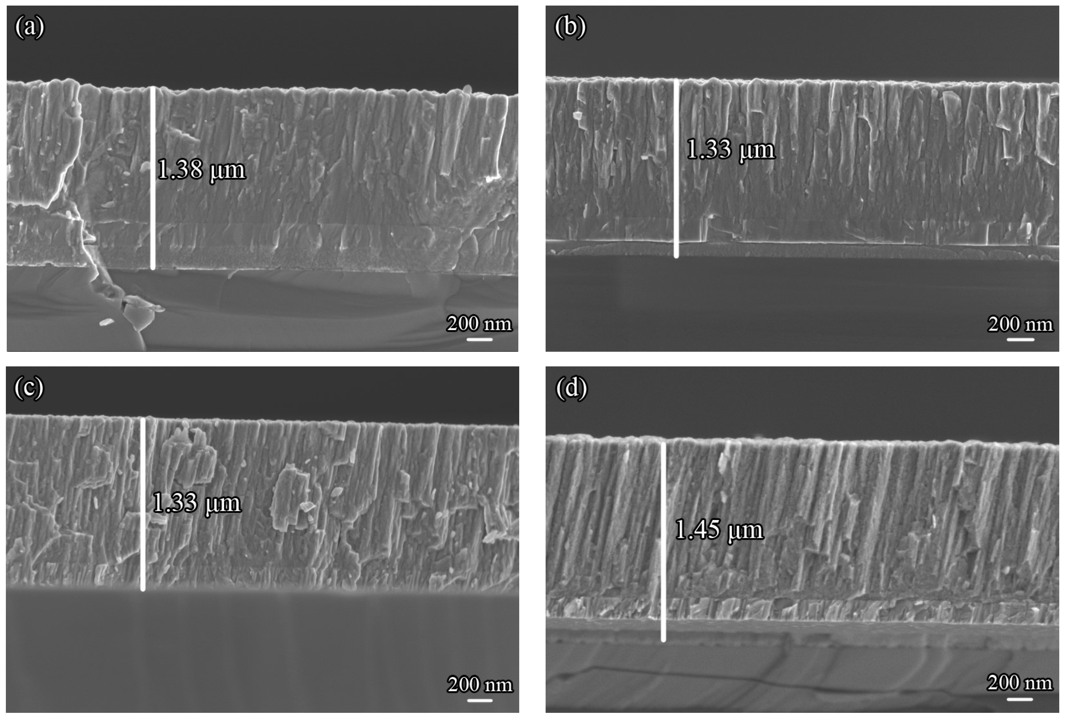
The chemical compositions of the four CrAlSiN coatings deposited under different Al sputtering power are presented in Figure 1. As the Al sputtering power increased from 0.6 to 1.2 kW, the Al content in the four CrAlSiN coatings increased from 11.4 to 17.6 at.% gradually, which was attributed to the fact that more Al atoms could be sputtered out, transported to and deposited on the substrate at higher sputtering power. The Cr content decreased a little with increasing Al sputtering power. The Si content versus Al sputtering power curve fluctuated a little and remained around 11.0 at.%. The N content in the four CrAlSiN coatings also varied a little around 41.0 at.%.
The XRD patterns of the four CrAlSiN coatings are shown in Figure 2. It can be seen that the main phase of the four CrAlSiN coatings consisted of singular cubic B1 NaCl type structure with multiple orientations of (111), (200) and (220) crystal planes. No diffraction peaks relating to phases like hexagonal close packed (hcp) AlN, Cr3Si, Si3N4 etc. were detected. It revealed that Al was dissolved in the CrN crystal lattice. The theoretical maximum solid solubility of Al in fcc-CrN is reported to be up to 0.77 (x = CAl/(CAl + CCr)) [15], while the practical solid solubility is usually lower than this value and varies in a large range depending on the deposition parameter. Si could also be partly dissolved into the CrN crystal lattice although the Si3N4 phase could be easily formed in the Cr–Si–N ternary coating thermodynamically [16,17]. The solid solubility of Si in fcc-CrN crystal lattice is still unclear. The four coatings contained about 11.0 at.% Si, and the Si3N4 phase was probably formed in this condition. However, the Si3N4 phase was not detected by XRD which indicated that it may have been in an amorphous state. The preferential orientation of all the four CrAlSiN coatings was the (200) crystal plane. The coating growth follows the principle of the lowest total energy including surface energy and strain energy [18]. The (200) crystal plane possesses the lowest surface energy, while the (111) crystal plane possesses the lowest strain energy [19]. When the surface energy is dominating in the total energy, the coating would grow along the (200) orientation [20].
Note that the diffraction peaks of the CrAlSiN coatings shifted to higher angles, and the diffraction peak of the (200) crystal plane became broader as the Al sputtering power increased from 0.6 to 1.2 kW. This might have been due to the diminution of the grain size of the CrAlSiN coatings. Figure 2b shows the average grain sizes of the CrAlSiN coatings calculated by Scherrer equation using (200) peaks. It can be seen that the grain size of the CrAlSiN coatings decreased gradually from 8.72 to 6.22 nm with increasing Al sputtering power. The lattice constants were also calculated using the Bragg equation using the same (200) peaks. The lattice constants of all the four CrAlSiN coatings were smaller than the standard lattice constants 4.14 Å (PDF# 11-0065), since the radii of Al and Si atoms are smaller than that of Cr, which renders that the replacement of Al and Si atoms for Cr atoms in the CrN crystal lattice decreasing the crystal lattice constants [7]. The lattice constants decreased gradually until the Al sputtering power reached 1.0 kW due to the dissolution of larger quantity of Al atoms. After that they were enlarged unexpectedly as less Al atoms would be dissolved in finer CrN crystals.

3.2. Microstructure

Figure 3 presents the surface morphologies of the four CrAlSiN coatings. As can be seen in Figure 3, the surface of all the four coatings was dense and composed of small irregularly shaped particles. The particle sizes became smaller when the Al sputtering power increased from 0.6 kW to 1.2 kW, which was due to the fact that the incorporation of Al element decreased the grain sizes of the fcc-(Cr,Al)N phase. However, it was obvious to observe that small granular particles aggregate into larger cauliflower structures on the surface of the CrAlSiN coating with Al sputtering power about 1.2 kW, resulting in rougher surface and more voids being generated. The surface roughness of the four CrAlSiN coatings was measured by surface profilometer, as shown in Figure 4. It decreased initially, and then increased when the Al sputtering power reached 0.8 kW. The CrAlSiN coating with 0.8 kW Al sputtering power possessed medium particle size and smallest surface roughness. While the CrAlSiN coating deposited with Al sputtering power about 1.2 kW possessed the highest surface roughness caused by the formation of uneven cauliflower structures.
Figure 5 displays the cross-sectional morphologies of the four CrAlSiN coatings. It can be seen that all the four coatings possessed columnar structure. The whole thicknesses of the CrAlSiN coatings were among 1.3 to 1.5 μm. There were two thin layers formed between the Si wafer and CrAlSiN coatings. To further investigate the microstructure of the coatings, bright field image with selected area electron diffraction (SAED) pattern and high-resolution morphologies of the CrAlSiN coating deposited with Al sputtering power at 0.8 kW are provided in Figure 6. Adjacent to the Si wafer was an amorphous layer containing Cr, Al and Si elements with thickness about 100 nm which was formed during the ion bombardment process. Since high negative bias voltage was applied in this process, metal ions were sputtered out and transported to the substrate with high velocities. Some of the metal ions would still be deposited on the substrate, while some of them would rebound back and even bombard the previously coated atoms deterring the crystallization of the deposited atoms. Beneath this amorphous zone was a Cr interlayer with columnar structure, which was aimed to connect the substrate and CrAlSiN coating enhancing the adhesive strength. The thickness of the Cr interlayer was approximately 190 nm, and the CrAlSiN layer was about 1.1 μm thick.
A higher-magnification image of the CrAlSiN layer is presented in Figure 6b. It further verified that the CrAlSiN coating possessed columnar structure with crystalline grains elongated along the growth direction. The columnar structure possessed clear boundaries and the diameter of single column was estimated between 50–100 nm. The SAED pattern of this zone consisted of polycrystalline rings which corresponded to (111), (200), (220) and (311) diffraction peaks of the fcc-CrN phase. It was consistent with the XRD diffraction outcomes that only the diffraction peaks of fcc-CrN phase were detected in the CrAlSiN coating. In Figure 6c, the columnar CrAlSiN layer seemed to be composed of multilayers (bilayer thickness ~3 nm). Since three individual Al, Cr and Si targets were used during the deposition process, alternate fcc-(Cr,Al,Si)N layers with slight composition difference might be formed. In the high-resolution image (Figure 6d), the coating microstructure was observed to be fcc-CrN crystal with (200) lattice fringes being surrounded by scattered amorphous phase. The continuing lattice fringes extended more than 9 nm which was three times larger than the bilayer thickness. It revealed that the CrAlSiN coating formed in epitaxy growth by the template effect. As mentioned above, the surface energy dominated the total energy. Thus, the CrAlSiN coating tended to grow in columnar structure with coherent interface, since it would minimize the interface energy [21]. In addition, the coherent interface might play a role in hindering the formation of amorphous zones, since only small-sized amorphous zones were found in Figure 6d.

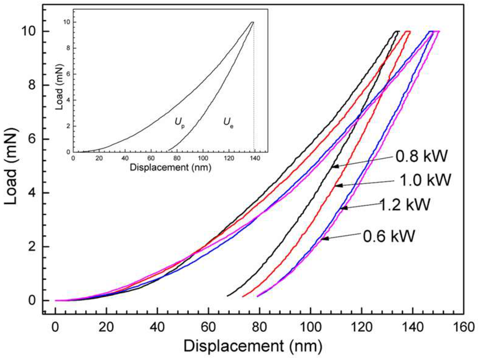
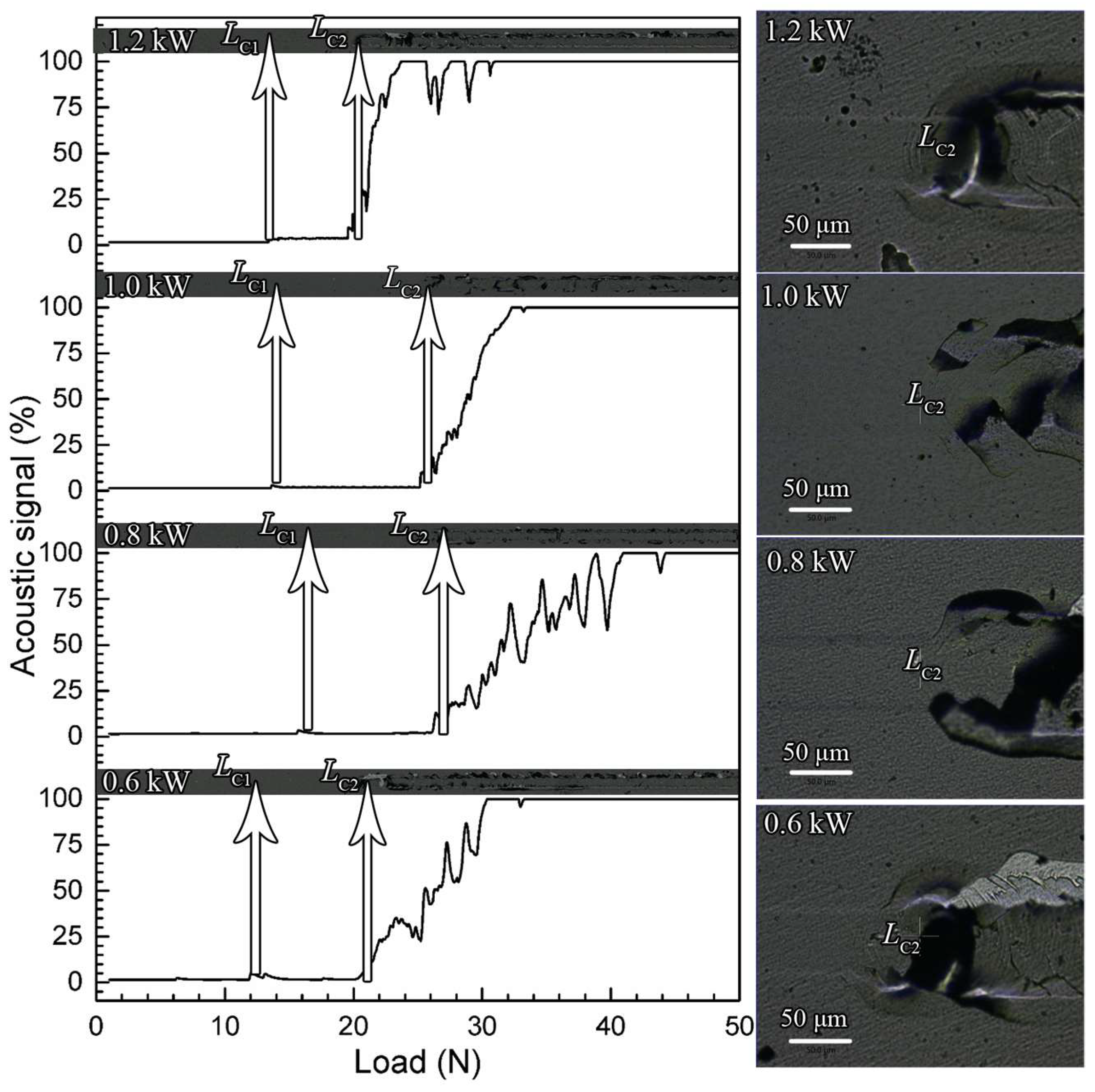
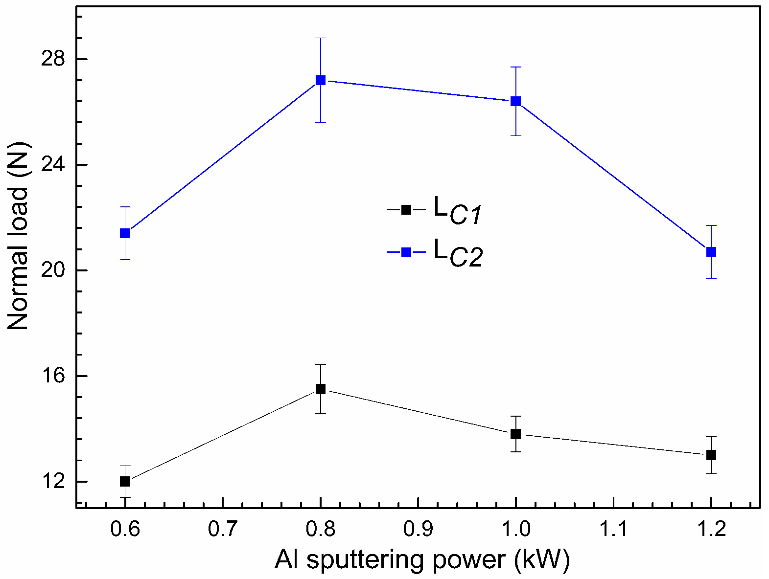
3.3. Mechanical Properties

The indentation load versus displacement curves of the four CrAlSiN coatings are presented in Figure 7. The maximum penetration depth of each coating was between 130 and 150 nm, nearly one tenth of the whole coating thickness. Under the same maximum indentation load, the CrAlSiN coating deposited at 0.8 and 0.6 kW Al sputtering power possessed the lowest and highest maximum penetration depth respectively. Hardness (H), elastic modulus (E*) and elastic recovery (We = Ue/(Ue + Up)) of the four coatings can be obtained from these curves. The elastic energy (Ue) and plastic energy (Up) are calculated from the area under the unloading curve and the area enclosed by the loading and unloading curves. The average hardness (H), elastic modules (E*), H/E*, H3/E*2 and elastic recovery (We) of the four CrAlSiN coatings are listed in Table 2. The hardness was enhanced from about 23.6 GPa to the maximum value 26.7 GPa, and then dropped down to 23.7 GPa again with enlargement of the Al sputtering power. The hardness was fortified firstly probably due to the refinement of the grain size, as presented in Figure 2b that the average grain size decreased gradually as the Al sputtering power increased. While the hardness decreased when the Al sputtering power was larger than 0.8 kW which might be ascribed to the aggregation of small particles resulting in rougher surface and defects formed in the coatings. Besides the coating grain size, the surface morphology, internal flaws like voids etc. also had great influence on the hardness of the coating. In addition, no super hardness phenomenon appeared in the four CrAlSiN coatings which might be due to the fact that clear columnar grain boundaries were formed in the coatings and they could acts as sites for cracking initiation under the indenter tip during nano-indentation measurement [22].
H/E*, H3/E*2, and We values are often used to estimate the toughness and crack resistance of a coating [23,24]. Some researchers report that the value H/E* is proportional to the resistance to fracture toughness of the coating, and the H3/E*2 is proportional to the resistance of the coating to plastic deformation [24,25]. The coating with higher We usually processes higher resistance to cracking [26,27]. According to Table 2, the H/E*, H3/E*2 as well as We values of the four CrAlSiN coatings possessed the same variation tendency as the hardness versus the Al sputtering power, except for the abnormal increase of the H/E* and H3/E*2 for the CrAlSiN coating deposited at 1.2 kW Al sputtering power. In general, the CrAlSiN coating deposited with Al sputtering power at 0.8 kW possessed the highest H, E*, H/E*, H3/E*2 and We values.
The adhesive strength was measured through a scratch tester. During the scratch test, slight cracking as well as chipping occurred firstly with slight oscillation of the friction and acoustical signals. It denoted the initial failure of the coating and the corresponding normal load at this stage was labeled as LC1. With further increasing the normal load, breakthrough would appear, and the coating peeled off with rapid intensified friction and acoustical signals which indicated the complete failure of the coatings and the critical load at this stage was denoted as LC2. Usually, the LC1 value reflects the intrinsic mechanical properties of the coating and the LC2 value can be regarded as the adhesive strength [28]. The friction signal could not be detected by the scratch tester used in this paper, therefore the LC1 and LC2 values were chosen mainly by combining the acoustic signal versus load curves and scratch images of the four CrAlSiN coatings, as shown in Figure 8. For all the four coatings, the acoustic signal versus load curves fluctuated slightly at an early phase, and then rebounded back to the smooth stage with very low intensity. Afterwards, large fluctuation of intensified acoustic signals appeared. At the same time, serious cracking and spallation could be observed both at the center and boundaries of the indentation zone. Then the acoustic signal was heightened rapidly to the maximum value that could be detected by the instrument, which indicated that severer cracking continued and the indenter had come into contact with the substrate. The normal load corresponding to the first slight fluctuation was marked as LC1, while the normal load with the second large fluctuation and appearance of large cracks was labeled as LC2.
The LC1 and LC2 values of the four CrAlSiN coatings obtained from Figure 8 are drawn in Figure 9. It can be seen that both of the LC1 and LC2 values of the CrAlSiN coatings were enhanced firstly and then dropped down subsequently, as the Al sputtering power increased. The CrAlSiN coating with 0.8 kW Al sputtering power possessed the maximum LC1 and LC2 values about 15.5 and 27.2 N respectively. The adhesive strength is relevant to hardness, surface roughness, residual stress, atomic bonding, compactness and defects in the coating [27,29]. High hardness is beneficial for decreasing the stress and plastic deformation of the contact zone between the coating and indenter, which results in higher resistance to cracking and better adhesion to the substrate. Elastic modulus (E*) also affects the adhesive strength. It is reported that higher H/E*, H3/E*2, and We values are in favor of enhanced adhesive strength [30,31]. The CrAlSiN coating with 0.8 kW Al sputtering power possessed the largest hardness, H/E*, H3/E*2 and We values which could explain for its high adhesive strength. The CrAlSiN coating with 1.2 kW Al sputtering power possessed higher H/E* and H3/E*2 values than the coatings deposited at 0.6 kW and 1.0 kW, but it had lower adhesive strength which might have been due to its larger surface roughness, since a rough surface would lead to higher internal stress accelerating the deformation and cracking of the coating.

4. Conclusions

Four CrAlSiN coatings with different Al contents were prepared by a combined method of HiPIMS and DCMS. All the four coatings possessed singular fcc-CrN phase with Al and part of Si dissolved in it. Amorphous phase also appeared in the coatings. All the four CrAlSiN coatings were (200) crystal plane oriented and possessed columnar structure formed by epitaxial growth. With increased the Al sputtering power, the grain and particle sizes of the coating became smaller, but small particles aggregated into larger particles when the Al sputtering power reached 1.2 kW leading to a rougher surface and more voids being generated.
As the Al sputtering power was enlarged, hardness increased firstly and then dropped down afterwards. The hardness was enhanced due to the refinement of grain size, while its decrease might be ascribed to aggregation of small particles resulting in a rougher surface and defects formed in the coating. The adhesive strength of the CrAlSiN coatings followed the same variation tendency with the hardness versus the Al sputtering power. The coating deposited with 0.8 kW Al sputtering power had the highest H (26.7 GPa), E* (383.5 GPa), H/E* (0.0696), H3/E*2 (0.1296), We (55.85%) and adhesive strength (27.2 N) indicating it possessed the best mechanical properties.

Author Contributions

Conceptualization, Q.F.; methodology, Q.F.; validation, Q.F. and Y.L. (Yangmengtian Liang); formal analysis, Q.F. and Y.L. (Yanmei Liu); investigation, Q.F., Y.L. (Yangmengtian Liang), Z.W., Y.L. (Yanmei Liu) and T.W.; resources, Q.F., Y.L. (Yangmengtian Liang), Z.W., Y.L. (Yanmei Liu) and T.W.; data curation, Q.F.; writing—original draft preparation, Q.F.; writing—review and editing, Q.F.; visualization, Q.F.; supervision, Q.F.; project administration, Q.F. and T.W.; funding acquisition, Q.F. and T.W.

Funding

This work was financially supported by the National Nature Science Foundation of China (No. 51501130), Tianjin Major Science and Technology Project of Military–Civil Integration (No. 18ZXJMTG00050), Research Development Foundation of Tianjin University of Technology and Education (No. KJ 1908), and Innovation Team Training Plan of Tianjin Universities and Colleges (No. TD13-5096).

Conflicts of Interest

The authors declare no conflict of interest.

References

  1. Tien, S.K.; Lin, C.H.; Tsai, Y.Z.; Duh, J.G. Effect of nitrogen flow on the properties of quaternary CrAlSiN coatings at elevated temperatures. Surf. Coat. Technol. 2017, 202, 735–739. [Google Scholar] [CrossRef]
  2. Kim, S.K.; Van Le, V.; Van Vinh, P.; Lee, J.W. Effect of cathode arc current and bias voltage on the mechanical properties of CrAlSiN thin films. Surf. Coat. Technol. 2008, 202, 5400–5404. [Google Scholar] [CrossRef]
  3. Fan, Q.; Zhang, J.; Wu, Z.; Liu, Y.; Yan, B.; Wang, T. Influence of Al content on the microstructure and properties of the CrAlN coatings deposited by arc ion plating. Acta Met. Sin. (English Lett.) 2017, 30, 1221–1230. [Google Scholar] [CrossRef]
  4. Zhang, S.; Wang, L.; Wang, Q.; Li, M. A superhard CrAlSiN superlattice coating deposited by a multi-arc ion plating: II. Thermal stability and oxidation resistance. Surf. Coat. Technol. 2013, 214, 153–159. [Google Scholar] [CrossRef]
  5. Chang, Y.-Y.; Lai, H.-M. Wear behavior and cutting performance of CrAlSiN and TiAlSiN hard coatings on cemented carbide cutting tools for Ti alloys. Surf. Coat. Technol. 2014, 259, 152–158. [Google Scholar] [CrossRef]
  6. Feng, Y.-P.; Zhang, L.; Ke, R.-X.; Wan, Q.-L.; Wang, Z.; Lu, Z.-H. Thermal stability and oxidation behavior of AlTiN, AlCrN and AlCrSiWN coatings. Int. J. Refract. Met. Hard Mater. 2014, 43, 241–249. [Google Scholar] [CrossRef]
  7. Kang, M.S.; Wang, T.-G.; Shin, J.H.; Nowak, R.; Kim, K.H. Synthesis and properties of Cr–Al–Si–N films deposited by hybrid coating system with high power impulse magnetron sputtering (HIPIMS) and DC pulse sputtering. Trans. Nonferrous Met. Soc. China 2012, 22, s729–s734. [Google Scholar] [CrossRef]
  8. Chang, C.-C.; Duh, J.-G. Duplex coating technique to improve the adhesion and tribological properties of CrAlSiN nanocomposite coating. Surf. Coat. Technol. 2017, 326, 375–381. [Google Scholar] [CrossRef]
  9. Chang, C.-C.; Chen, H.-W.; Lee, J.-W.; Duh, J.-G. Development of Si-modified CrAlSiN nanocomposite coating for anti-wear application in extreme environment. Surf. Coat. Technol. 2015, 284, 273–280. [Google Scholar] [CrossRef]
  10. Li, B.; Wang, T.; Ding, J.; Cai, Y.; Shi, J.; Zhang, X. Influence of N2/Ar flow ratio on microstructure and properties of the AlCrSiN coatings deposited by high-power impulse magnetron sputtering. Coatings 2018, 8, 3. [Google Scholar] [CrossRef]
  11. Lundin, D.; Sarakinos, K. An introduction to thin film processing using high-power impulse magnetron sputtering. J. Mater. Res. 2012, 27, 780–792. [Google Scholar] [CrossRef] [Green Version]
  12. Wang, L.; Li, L.; Kuang, X. Effect of substrate bias on microstructure and mechanical properties of WC-DLC coatings deposited by HiPIMS. Surf. Coat. Technol. 2018, 352, 33–41. [Google Scholar] [CrossRef]
  13. Sarakinos, K.; Alami, J.; Konstantinidis, S. High power pulsed magnetron sputtering: A review on scientific and engineering state of the art. Surf. Coat. Technol. 2010, 204, 1661–1684. [Google Scholar] [CrossRef]
  14. Lou, B.-S.; Yang, Y.-C.; Qiu, Y.-X.; Diyatmika, W.; Lee, J.-W. Hybrid high power impulse and radio frequency magnetron sputtering system for TiCrSiN thin film depositions: Plasma characteristics and film properties. Surf. Coat. Technol. 2018, 350, 762–772. [Google Scholar] [CrossRef]
  15. Makino, Y.; Nogi, K. Synthesis of pseudobinary Cr–Al–N films with B1 structure by rf-assisted magnetron sputtering method. Surf. Coat. Technol. 1998, 98, 1008–1012. [Google Scholar] [CrossRef]
  16. Park, J.H.; Chung, W.S.; Cho, Y.-R.; Kim, K.H. Synthesis and mechanical properties of Cr–Si–N coatings deposited by a hybrid system of arc ion plating and sputtering techniques. Surf. Coat. Technol. 2004, 188, 425–430. [Google Scholar] [CrossRef]
  17. Wang, Q.M.; Kim, K.H. Microstructural control of Cr–Si–N films by a hybrid arc ion plating and magnetron sputtering process. Acta Mater. 2009, 57, 4974–4987. [Google Scholar] [CrossRef]
  18. Ma, F.; Li, J.; Zeng, Z.; Gao, Y. Structural, mechanical and tribocorrosion behaviour in artificial seawater of CrN/AlN nano-multilayer coatings on F690 steel substrates. Appl. Surf. Sci. 2018, 428, 404–414. [Google Scholar] [CrossRef]
  19. Chen, H.-W.; Chan, Y.-C.; Lee, J.-W.; Duh, J.-G. Oxidation resistance of nanocomposite CrAlSiN under long-time heat treatment. Surf. Coat. Technol. 2011, 206, 1571–1576. [Google Scholar] [CrossRef]
  20. Je, J.H.; Noh, D.Y.; Kim, H.K.; Liang, K.S. Preferred orientation of TiN films studied by a real time synchrotron X-ray scattering. J. Appl. Phys. 1997, 81, 6126–6133. [Google Scholar] [CrossRef]
  21. He, L.; Chen, L.; Xu, Y. Interfacial structure, mechanical properties and thermal stability of CrAlSiN/CrAlN multilayer coatings. Mater. Charact. 2017, 125, 1–6. [Google Scholar] [CrossRef]
  22. Stueber, M.; Holleck, H.; Leiste, H.; Seemann, K.; Ulrich, S.; Ziebert, C. Concepts for the design of advanced nanoscale PVD multilayer protective thin films. J. Alloy. Compd. 2009, 483, 321–333. [Google Scholar] [CrossRef]
  23. Ding, X.-Z.; Zeng, X.; Liu, Y. Structure and properties of CrAlSiN nanocomposite coatings deposited by lateral rotating cathod arc. Thin Solid Films 2011, 519, 1894–1900. [Google Scholar] [CrossRef]
  24. Zhang, S.; Wang, L.; Wang, Q.; Li, M. A superhard CrAlSiN superlattice coating deposited by multi-arc ion plating: I. Microstructure and mechanical properties. Surf. Coat. Technol. 2013, 214, 160–167. [Google Scholar] [CrossRef]
  25. Chang, C.-C.; Chen, H.-W.; Lee, J.-W.; Duh, J.-G. Influence of Si contents on tribological characteristics of CrAlSiN nanocomposite coatings. Thin Solid Films 2015, 584, 46–51. [Google Scholar] [CrossRef]
  26. Musil, J.; Jílek, R.; Meissner, M.; Tölg, T.; Čerstvý, R. Two-phase single layer Al–O–N nanocomposite films with enhanced resistance to cracking. Surf. Coat. Technol. 2012, 206, 4230–4234. [Google Scholar] [CrossRef]
  27. Liu, Y.; Jiang, C.; Pei, Z.; Lei, H.; Gong, J.; Sun, C. Microstructure and properties of AlB2-type WB2 thin films deposited by direct-current magnetron sputtering. Surf. Coat. Technol. 2014, 245, 108–116. [Google Scholar] [CrossRef]
  28. Li, T.; Li, M.; Zhou, Y. Phase segregation and its effect on the adhesion of Cr–Al–N coatings on K38G alloy prepared by magnetron sputtering method. Surf. Coat. Technol. 2007, 201, 7692–7698. [Google Scholar] [CrossRef]
  29. Attar, F.; Johannesson, T. Adhesion evaluation of thin ceramic coatings on tool steel using the scratch testing technique. Surf. Coat. Technol. 1996, 78, 87–102. [Google Scholar] [CrossRef]
  30. Wu, W.; Chen, W.; Yang, S.; Lin, Y.; Zhang, S.; Cho, T.-Y.; Lee, G.; Kwon, S.-C. Design of AlCrSiN multilayers and nanocomposite coating for HSS cutting tools. Appl. Surf. Sci. 2015, 351, 803–810. [Google Scholar] [CrossRef]
  31. Li, Z.; Munroe, P.; Jiang, Z.; Zhao, X.; Xu, J.; Zhou, Z.; Jiang, J.; Fang, F.; Xie, Z. Designing superhard, self-toughening CrAlN coatings through grain boundary engineering. Acta Mater. 2012, 60, 5735–5744. [Google Scholar] [CrossRef]
Figure 1. Chemical compositions of the four CrAlSiN coatings deposited under different Al sputtering power.
Coatings 09 00512 g001
Figure 2. (a) XRD patterns of the four CrAlSiN coatings; (b) lattice constants and grain sizes calculated from (200) diffraction peaks in (a).
Coatings 09 00512 g002
Figure 3. Surface images of the four CrAlSiN coatings deposited under different Al sputtering power (a) 0.6 kW (b) 0.8 kW (c) 1.0 kW and (d) 1.2 kW.
Coatings 09 00512 g003
Figure 4. Surface roughness of the four CrAlSiN coatings deposited under different Al sputtering power.
Coatings 09 00512 g004
Figure 5. Cross-sectional images of the four CrAlSiN coatings deposited under different Al sputtering power (a) 0.6 kW (b) 0.8 kW (c) 1.0 kW and (d) 1.2 kW.
Coatings 09 00512 g005
Figure 6. TEM images of the CrAlSiN coating deposited with Al target power about 0.8 kW. (a) Bright field image of the whole coating, (b) magnified bright field image with selected area electron diffraction (SAED) pattern of the CrAlSiN layer, (c) magnified bright field image of the coating and (d) high resolution morphology of the CrAlSiN layer.
Coatings 09 00512 g006
Figure 7. Representative load versus displacement curves of the four CrAlSiN coatings deposited under different Al sputtering power.
Coatings 09 00512 g007
Figure 8. Acoustic signal versus load curves and scratch images of the four CrAlSiN coatings deposited under different Al sputtering power.
Coatings 09 00512 g008
Figure 9. Critical load (LC1 and LC2) values of the four CrAlSiN coatings deposited under different Al sputtering power.
Coatings 09 00512 g009
Table 1. Deposition parameters of the four CrAlSiN coatings deposited under different Al sputtering power.
ParametersValue
Base pressure (Pa)1.0 × 10⁻³
Working pressure (Pa)0.5
Bias voltage (V)−30
Ar flow (SCCM)47
N2 flow (SCCM)94
Deposition temperature (°C)300
Deposition time (min)180
Sputtering power of Al target (kW)0.6, 0.8, 1.0, 1.2
Sputtering power of Cr target (kW)1.0
Sputtering power of Si target (kW)0.6
Rotation speed of the sample (r/min)30
Distance between the substrate and target (mm)70
Table 2. Hardness (H), effective elastic modulus (E*), H/E*, H3/E*2 and elastic recovery (We) of the four CrAlSiN coatings deposited with Al sputtering power ranging from 0.6 to 1.2 kW.
Al Target Power (kW)H (GPa)E* (GPa)H/E*H3/E*2We%
0.623.6 ± 0.9373.3 ± 16.80.0633 ± 0.00160.0949 ± 0.005851.85 ± 0.99
0.826.7 ± 1.5383.5 ± 16.60.0696 ± 0.00140.1296 ± 0.008255.85 ± 1.66
1.025.3 ± 0.6371.5 ± 19.00.0681 ± 0.00150.1176 ± 0.006755.19 ± 1.34
1.223.7 ± 2.0346.7 ± 35.10.0683 ± 0.00210.1128 ± 0.014152.95 ± 2.11

