Article

Compositional, Optical and Electrical Characteristics of SiOx Thin Films Deposited by Reactive Pulsed DC Magnetron Sputtering

by
Joaquim O. Carneiro
1,*,
Filipe Machado
1,
Luis Rebouta
1,
Mikhail I. Vasilevskiy
2,3,
Senen Lanceros-Méndez
2,4,
Vasco Teixeira
1,
Manuel F. Costa
2,* and
Anura P. Samantilleke
1
1
Centre of Physics, Department of Physics, University of Minho, Azurém Campus, 4800-058 Guimarães, Portugal
2
Centre of Physics, Department of Physics, University of Minho, Gualtar Campus, 4710-057 Braga, Portugal
3
International Iberian Nanotechnology Laboratory, Avenida Mestre José Veiga, 4715-330 Braga, Portugal
4
Basque Center for Materials, Applications and Nanostructures, UPV/EHU Science Park, 48940 Leioa, Spain
*
Authors to whom correspondence should be addressed.
Coatings 2019, 9(8), 468; https://doi.org/10.3390/coatings9080468
Submission received: 20 June 2019 / Revised: 18 July 2019 / Accepted: 22 July 2019 / Published: 25 July 2019

Abstract

:
The influence of O2 flow rate on the compositional, optical and electrical characteristics of silicon oxide (SiOx) thin films (x < 2) were studied in this work. The SiOx thin films were obtained by pulsed direct current (DC) magnetron sputtering (PMS) onto n-type Si wafers (and also on glass substrates) at a vacuum of 3 × 10⁻³ Pa. Rutherford backscattering spectrometry (RBS) was used to check the compositional elements of deposited films and its oxidized states were analysed via Fourier-transform infrared (FTIR) spectroscopy. The optical properties of as-deposited SiOx thin films were investigated from transmittance measurements at room temperature in the wavelength range of 250–800 nm. The obtained data reveal that the Urbach energy (a measure of the band tail extension, Eu) decreased from about 523 to 172 meV as the rate of oxygen gas flow increased. On the contrary, the optical energy band-gap (Eg) increased from 3.9 to 4.2 eV. Conduction and valance band positions (relative to the normal hydrogen electrode) were also evaluated. The observed behavior is probably associated with the degree of disorder and defects presented in the as-deposited SiOx thin films, probably due to the presence of newly inserted oxidized OnSiHy species resulting from some contamination with water vapor desorbed from the walls of the deposition vacuum chamber. After deposition of a gold top electrode, the electrical characteristics of the fabricated Au/SiOx/n-Si system (i.e., a metal/insulator/semiconductor structure—MIS) were studied via characteristic I-V curves and their dependence upon the O2 flow rate are reported. It was observed that the Au/SiOx/n-Si structure behaves like a Schottky-diode exhibiting a very good diode rectifying performance with a rectification ratio of at least 300 and up to 104, which refers to the samples produced with the lower and higher O2 flow rates, respectively. It was also found that the O2 flow rate influences the rectifying performance of the SiOx/n-structures since both the diode ideality factor, n, and the diode series-resistance, RS decreases with the increase of O2 content, possibly reflecting a closer approximation to a full stoichiometric condition.

1. Introduction

In recent years, silicon oxide (SiOx) based coatings (a combination of stoichiometric oxide (SiO2) with a non-stoichiometric sub-oxide (SiOx, x < 2) [1]) have been studied due to their technological importance in numerous applications, including microelectronics [2], communication [3], pharmaceutical, food and packaging industries [4,5]. The use of silicon oxide coatings as a dielectric insulator of electronic switches and sensing devices such as thin-film transistors (TFTs), metal-insulator-semiconductor (MIS) switching devices, optical coatings and optoelectronic applications or even in processes associated with the fabrication of micro-electromechanical-systems (MEMS), serving for example, as etch masks in bulk micromachining or as sacrificial layer in surface micromachining processes [6,7,8,9] is particularly noteworthy due to its properties, as SiOx compounds are known to have good abrasion resistance, electrical insulation, high thermal stability and also being insoluble in the majority of acids. There are several techniques to produce silicon dioxide films among which one of the most common is the thermal oxidation method [10,11,12]. However, this thermal technique presents some drawbacks such as high temperature, which is usually higher than 900 °C, highly clean surface required for diffusion process, low deposition rate (it may need hours for moderately thick coatings) and also the requirement of silicon wafer as the only substrate. Fortunately, there are other deposition techniques that can be used to produce SiOx coatings such as direct current (DC) reactive magnetron sputtering (MS) [13,14], electron beam evaporation with ion assistance [15,16,17], low-pressure chemical vapour deposition (LPCVD) [18], hot filament chemical vapour deposition (HFCVD) [19] and plasma-enhanced chemical vapour deposition (PECVD) [20]. However, since LPCVD, HFCVD, and PECVD deposition techniques require high temperature, these techniques are not suitable for materials with low melting point.
Sputtering techniques are clearly suitable to deposit silicon dioxide thin films. The utilization of MS technique to deposit metal oxides coatings can lead to the generation of arcs and plasma instability. On the other hand, reactive pulsed DC magnetron sputtering (PMS), besides being able to reduce or even eliminate arcs, this technique can also be used to deposit at low-temperature metal oxide-based coatings with high-quality characteristics [21,22] and also, when compared with radio frequency (RF) sputtering, PMS technique is a relatively more competitive and attractive deposition method because it implies low-cost in industrial settings for mass production.
Although in recent years most of the research work performed in the field of physical deposition of metal oxide-based coatings has been devoted to RF sputtering technique, it appears that much fewer studies have been reported on the development and characterization of silicon oxide-based thin films by produced by PMS technique. In this sense, the main motivation and contribution of this work is to complement the investigation, study and estimation of some other optical and electrical properties of SiOx thin films, which have not been exposed in previous literature studies, which mainly refers to Urbach’s parameters [23] and Schottky-diode [24,25,26] rectifying characteristics of SiOx/n-Si structures (after the deposition of a Au top electrode onto its surface) produced by PMS deposition method. In particular, our goal is to discuss the correlation between these parameters (band tail width, Eu, energy band-gap, Eg, diode ideality factor, n, and diode series-resistance, Rs) with the different amounts of O2 gas flow utilized in the fabrication of SiOx/n-Si structures.

2. Experimental Details

2.1. Deposition of SiOx Thin Films by Pulsed DC Magnetron Sputtering

Traditionally, DC reactive magnetron sputtering can be separated into three different modes, namely (I) the metallic, (II) the transition and (III) the compound (or reactive) mode. These operation ‘regimes’ are a function of the amount of used reactive gas during deposition [27]. By using reactive pulsed DC magnetron sputtering technique, it is possible to minimize or even suppress the generation of arcing events in the target surface, which result from its poisoning during the compound mode. Specific details of PMS deposition method have already been described in our previous work [28]. Briefly, in PMS deposition method there are two different parameters that are experimentally adjusted in the voltage waveform, which refer to the pulsed frequency, f and the reverse time, tr.
These two parameters are related to the so-called reverse phase, τr through the following relation: τr (%) = (tr × f) × 100, where f is the frequency of the applied pulse. It should be noted that most commercial available pulsed sources limit the reverse voltage (i.e., the target positive voltage, Vr) to a value that typically corresponds to 10% of the negative applied voltage, V0. This practice is sufficient to effectively dissipate the charged regions and thus prevent arcing events. In this work, the SiOx thin films were deposited on n-type 380-μm-thick (100) Si wafers by using a homemade PMS system).
It is important to mention that, in order to perform transmittance spectroscopy over the SiOx thin films, glass substrates were also used in the same deposition conditions. The target used in this work was a Si disk (purity 99.99%) with a diameter of 70 mm and the used target-to-substrate distance (z) was z = 70, 80 and 90 mm in which the shortest distance (z = 70 mm), was utilized to deposit samples with the highest O2 gas flow and the largest one (z = 90 mm) was selected to produce samples with the lowest O2 gas flow. After evacuating the chamber to a base pressure lower than 3 × 10⁻³ Pa, the target surface was firstly etched (during 15 min) by Ar+ ion bombardment while the shutter was kept closed to prevent contamination of the substrate with any undesirable material. After the etching step, O2 gas was injected into the chamber through a 6 mm gas ring opening located at about 100 mm from the magnetron-sputtering source. The sputtering of target surface proceeded at a working pressure of about 1.4 × 10⁻¹ Pa and under a constant current of 0.35 A (current density of 9.1 mA/cm2). A mass-flow controller (Bronkhorst, Suffolk, UK) was used to measure the Ar and O2 flows. For all produced samples, the argon flow was kept at a constant value of 8 sccm while the flow of O2 gas was varied in order to obtain SiOx coatings grown under three different O2 gas flows, corresponding to samples that from now will be identified (ID) as @1.4, @1.6 and @2.0. The deposition time for all the produced SiOx coatings was 60 min. The main deposition parameters are shown in Table 1.

2.2. Film Characterization

Fourier transform infrared (FTIR) spectroscopy was used in order to obtain structural information for the as-deposited SiOx thin films. FTIR spectra were acquired on an IR Affinity-1S spectrophotometer (Shimadzu, Kyoto, Japan) in a frequency range from 380 to 4000 cm−1. Rutherford backscattering spectrometry (RBS) measurements were carried out at the CTN/IST Van de Graaff accelerator with detectors placed at 165° to the beam direction using a 2 meV 4He+ beam. Normal incidence was used in the experiments and the obtained data were analyzed with the IBA Data Furnace [29].
Optical studies were performed to determine the absorption coefficient α(λ), the band tail width quantified by the so-called Urbach energy (Eu) and the optical gap (Eg). These optical parameters were obtained by using transmission T(λ) measurements performed with a UV-3101PC UV–Vis-NIR spectrophotometer (Shimadzu, Kyoto, Japan). The transmittance signal was collected from 250 to 800 nm with a resolution of 1.0 nm. The film’s surface morphology was obtained by scanning electron microscopy (SEM) (NanoSEM—FEI Nova 200 (FEG/SEM) equipment, FEI, Hillsboro, OR, USA).
In order to investigate the electrical characteristics of the SiOx/n-Si system, current-voltage (I-V) characteristic curves were measured by means of a Keithley 487 picoammeter (Keithley, Cleveland, OR, USA)/voltage source under a voltage range from −1.0 to 1.0 V in steps of 0.1 V. It is important to note that before acquiring the I-V characteristic curves, gold and aluminum contacts were firstly deposited as top and back electrodes, respectively on the SiOx/n-Si heterostructure (see Figure 1), which resembles a Schottky diode structure [24].
The Au top electrode was deposited with a circular shadow mask (1.0 mm diameter) on the SiOx surface by resistive thermal evaporation of 34 mg of gold (from an Au wire with 0.5 mm diameter) previously placed inside a tungsten boat. Complete evaporation of the Au wire was attained by applying a current of 200 A under a voltage of 1.0 V for 1 min, which ensured the deposition of an Au layer of about 150 nm (estimated from SEM analysis).

3. Results and Discussion

3.1. Target Voltage Control Method and Hysteresis Effect

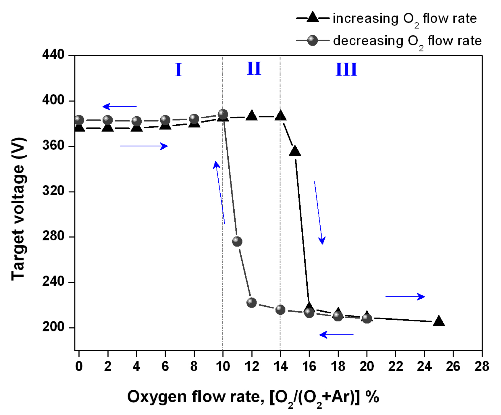
The most used and reliable technique in controlling reactive sputtering processes is the so-called target voltage control method, a simple and low-cost procedure. Figure 2 shows the target voltage as a function of the oxygen gas flow rate [O2/(O2 + Ar)]%, which presents a hysteresis loop.
As can be observed, for low values of O2 gas flow rate (region I), the sputtered “metal” gathers almost all the available reactive gas because target voltage has practically no changes and the deposited film is under the so-called “metallic” mode (“metal”-rich). However, as the reactive gas flow rate continues to increase until it reaches a certain critical value, one can observe a sharp decrease in the target voltage, which corresponds to the point where the target becomes poisoned (the compound mode, i.e., region III). Under this condition, the sputtered “metal” does not fully gather the flow rate of the reactive gas entering into the deposition chamber, thus the deposited films should be reactive gas-rich. It is noteworthy that the variations of the target voltage depend on changes in target surface composition as it determines the amount of secondary electrons emitted by ion bombardment on the target surface [30]. Once the target is poisoned, its voltage does not change following the same path to return to the “metallic mode”, as the level of O2 reactive gas remains still high until the compound layer, which was previously formed on the target surface, is entirely removed uncovering original target material.
Therefore, according to the deposition parameters presented in Table 1, the sample identified as @1.4, having been deposited at the lower limit of the compound mode, is expected to lead to a silicon-rich and oxygen-deficient coatings. The samples coded as @1.6 and @2.0 are likely to be O2 richer and hence, possibly closer to the stoichiometric condition.
It is important to refer that, for the same deposition times, the use of different O2 gas flow directly influences the thickness (d) of the SiOx films, unless the target-to-substrate distance is suitably varied. In this work, the thickness d ≈ 500 nm (determined from SEM) of the as-deposited SiOx films is basically the same and this was achieved through an empirical adjustment (trial and error) of the target-to-substrate distance.
The thickness of a coating produced by magnetron sputtering is related to its growth rate, which in turn is influenced by the sputter yield (Y) and also on the mean free path of target atoms. Considering elastic binary collisions, only kinetic energy is exchanged, while the potential energy is conserved as it mainly resides within the electronic structure of the colliding atoms, ions, molecules, etc.) [31]. Taking elastic binary and central collisions between atoms, and assuming that one of the atoms is initially stationary, the well-known result is
χ   =   ( E 2 E 1 )   =   4 m 1 m 2 ( m 1   +   m 2 ) 2
where m1 and m2 refer to the mass of incident and target atoms, respectively, whereas E1 is the initial kinetic energy of the incident atom and E2 is the energy of target atom after collision. The quantity 4m1m2/(m1 + m2)2 (or E2/E1) is known as the energy transfer function, χ.
For example, if m1 = m2 then χ = 1, that is, after collision the initial moving atom is stopped, and its kinetic energy is totally transferred to the second atom, which moves away. In this work, the incident “particles” are argon atoms (Ar ≈ 39.9 amu) and taking the target composed by silicon atoms (Si ≈ 28.08 amu), its energy transfer function is χSi = 0.969, which is quite close to unity and thus, resulting in a safe arrival of Si atoms to the substrate. On the other hand, if the target surface is poisoned with the oxygen reactive gas (i.e., the silicon atoms are shielded by O atoms), the energy transfer function for oxygen (O ≈ 15.99 amu) is χO = 0.817. This means that, during collisions, argon atoms transfer much less energy to the oxygen ones. In this sense, any eventual collision occurring between Ar and O during the path of the O atoms from the target to the substrate will result in moving away the O atoms because in general, they may not have gained enough energy to overcome the target-to-substrate distance. This condition leads to a decrease in the amount of oxygen in the substrate, which has direct repercussions on the thickness (decrease) of the deposited coating. Meanwhile, the sputter yield is the number of atoms (or molecules) ejected from a target surface per incident atom (ion) and is a measure of the efficiency of sputtering [31]. The sputter yield is proportional to the energy transfer function and varies inversely with the surface binding energy (Eb) of a particular atom [32]
Y χ E 2 E 1
It is interesting to evaluate the order of magnitude for the ratio between the sputter yields for silicon and oxygen. The binding energies for silicon and oxygen are 4.73 and 6.79 eV, respectively [33]. The application of Equation (2) predicts that the oxygen sputter yield is almost half that of the silicon, that is, YO/YSi = 0.587. This is the reason why that, in this work, the target-to-substrate distance was slightly varied, since the shortening of the target-to-substrate distance represents a strategy to counteract the effect of a lower sputtering yield. Since all the produced samples were essentially deposited under the same working pressure (1.4 × 10⁻¹ Pa), then the mean free path for each sputtered atom is basically the same. Therefore, a smaller target-to-substrate distance decreases the probability of sputtered atoms to be scattered by incident argon ions, and thereby causing an increase of the growth rate and, consequently, in the achieved thickness.
In this sense, one can expect that for elements having lower sputter yields and sputtered with lower target-to-substrate distances would form coatings with thicknesses similar to those formed by elements that have been sputtered with higher sputter yields, but at longer target-to-substrate distances.

3.2. Film Characteristics

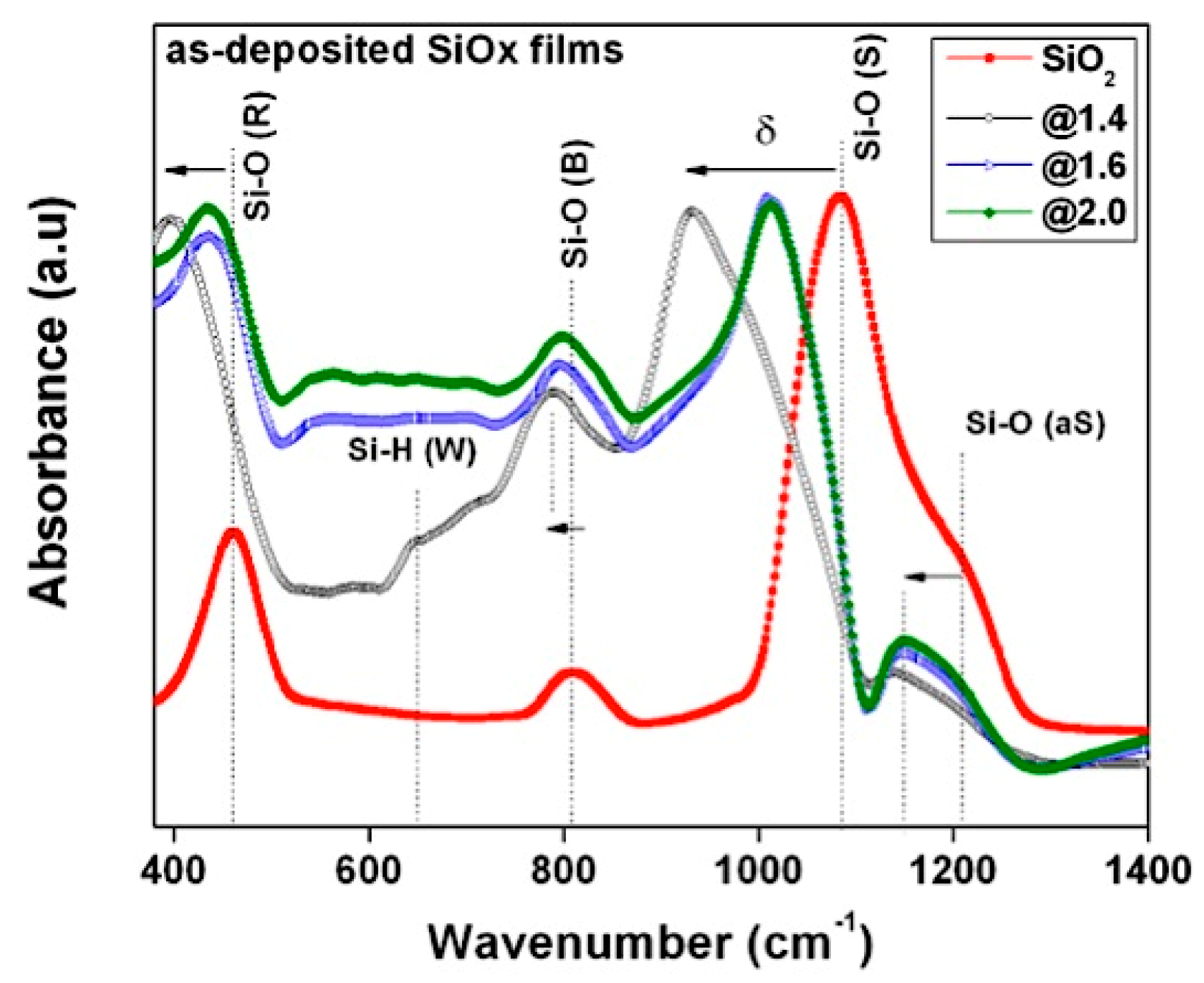
It is well known that infrared spectroscopy (IR) is a powerful tool to monitor the change of oxidized states due to its high sensitivity to molecular structures. The IR absorption spectra of the SiOx films deposited with three different flow rates of O2 reactive gas were measured by using FTIR covering a wavenumber range from 380 to 4000 cm−1. In order to compare the oxidized states of the as-deposited SiOx thin films with the fully stoichiometric silicon dioxide (or silica/SiO2), a IR absorption spectrum was also performed on pure silica, in its powder form (0.5 μm particle size), previously purchased from Sigma-Aldrich (Saint Louis, MO, USA). Figure 3 shows the IR absorption spectra of SiOx films (and also of silica for comparison) acquired in the low-frequency region (380 to 1400 cm−1). Table 2 presents the peaks’ position of the Si–O bonds.
Three main absorption characteristic peaks of Si–O–Si group, namely 461 cm−1 for the Si–O vibration rocking mode, 810 cm−1 for the Si–O bending mode and 1082 cm−1 for the Si–O stretching mode can be identified by analyzing the IR spectra [34,35]. In fact, the main information extracted from the examination of IR spectra refers to a downward shift toward a lower wavenumber that occurs for the generality of the peaks’ position of Si–O bonds as the O2 gas flow is decreased. For example, the strongest absorption peak is ascribed to the Si–O stretching vibration mode where its position shifted from 1082 cm−1 (stoichiometric SiO2) towards a lower frequency of 932 cm−1, which corresponds to SiOx thin films produced under the lower O2 flow rate. These results indicate that the decrease of O2 content promotes a change in the oxidation state of the as-deposited films, from an oxygen excess to a more silicon-rich thin films (non-stoichiometric) where the Si–O bonds are progressively replaced by Si–Si bonds [37]. Additionally, it is also observed that the shoulder (1203 cm−1) existing in stoichiometric SiO2, assigned to the out of phase stretching (or asymmetric stretching mode) mode of Si–O–Si [34,35], changes to a prominent peak, which slightly moves toward a lower frequency as O2 gas flow rate is decreased. Moreover, it was also calculated the ratio of absorption intensities between the peaks associated with the in-phase and out of phase stretching modes. The ratio for stoichiometric SiO2 is 0.38, whereas for the as-deposited SiOx films, it decreases as the O2 gas flow also decrease, namely from 0.23, 0.19 to 0.17, corresponding to the samples @2.0, @1.6, and @1.4, respectively. These results reveal that as the O2 gas flow is reduced, the obtained ratios are further away from that of the stoichiometric SiO2. According to the results shown in Table 2 and also in Figure 4, it is suggested that the main physical reason for the shift of the characteristic dipole-active vibration modes towards lower frequencies (Si-rich films) with the increase of the deviation from stoichiometry, δ is related to the increase in the average bond length, so it becomes less stiff.
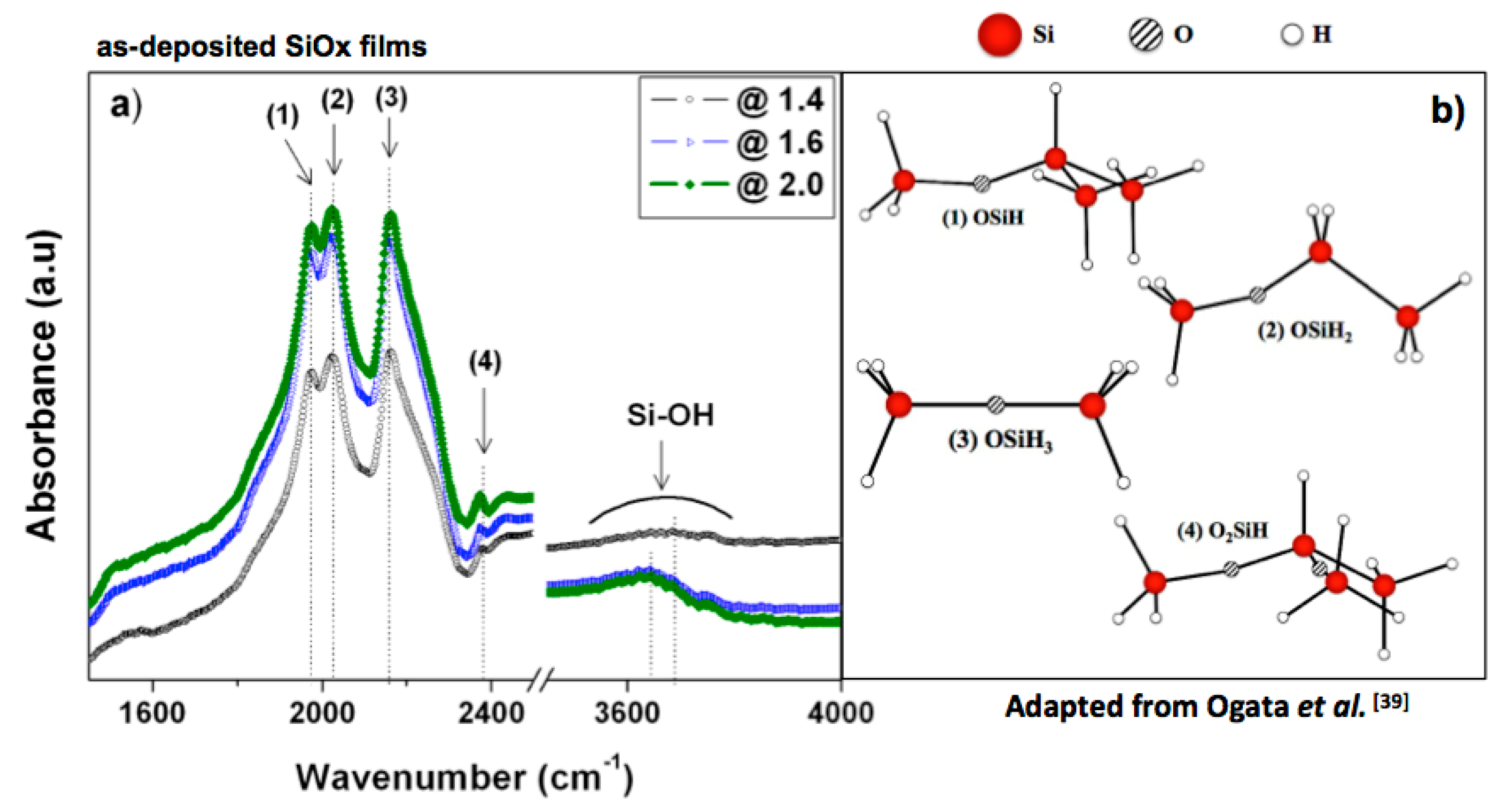
In addition, Figure 3 also shows a weak absorption peak at 648 cm−1 detected for the SiOx film deposited under the lower oxygen content (i.e., the @1.4 sample), which has been identified as being associated with Si–H wagging bonds [38]. The surprising appearance of hydrogen atoms has raised our interest in extending the FTIR spectra to the region of high frequencies. Figure 4a presents the IR absorption spectra for the SiOx films deposited under different O2 gas flows in the range from 1400 to 4000 cm−1. The FTIR spectra show four distinct Si–H stretching vibrations at 1980, 2025, 2162, and 2376 cm−1, which can be ascribed to the –OSi–H, –OSi–H2, –OSi–H3, and –O2Si–H partially oxidized structures [39], respectively. The geometries of these structures [39] are shown in Figure 4b and the corresponding vibration modes of those different oxidized states are presented in Table 3.
The weak but broadband absorptions shown in Figure 4a around 3650 cm−1 are due to the presence of H2O and are attributed to the O–H stretching vibrations. This suggests that during the high vacuum phase of the deposition process, some amount of water vapor was desorbed from the walls of the vacuum chamber. Therefore, the “atmosphere” within the chamber was undesirably contaminated with hydrogen and additional oxygen atoms during the deposition process. Under this scenario, it has been pointed out that the presence of water promotes oxidation acceleration, once H2O is capable of attacking and breaking a Si–Si bond, thus producing extra SiH and SiOH species [40]. These newly inserted SiHx species are now quite likely to experience further oxidation to form OnSiHx species (where n = 1 to 3 and x = 1 to 3) [39]. In this condition, the presence of H2O acts as an additional and contaminating source of hydrogen atoms. In this sense, it is suggested that hydrogen atoms are capable of competing with the reactive O2 gas to form bonds with the silicon atoms that have been sputtered by Ar+ ion bombardment. Thus, it will be quite improbable to obtain a stoichiometric SiO2 film and instead, non-stoichiometric silicon oxide SiOx films should predominate in the presence of another type of partially oxidized species in the form of OnSiHx species.
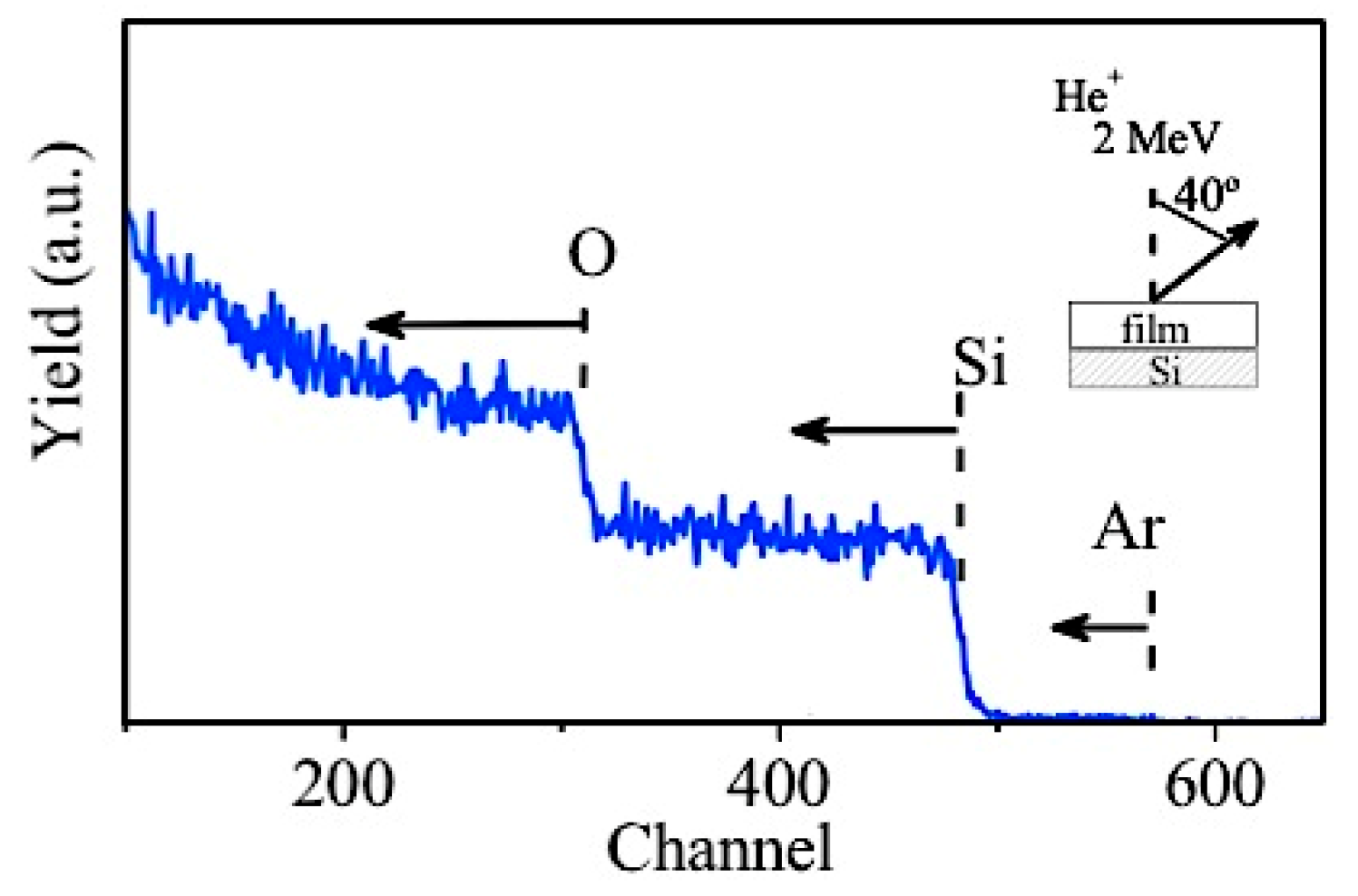
Figure 5 shows the RBS spectrum for the @1.4 sample, with a composition of 33.7 at %, 65.9 at % and 0.4 at % of Si, O, and residual Ar, respectively.
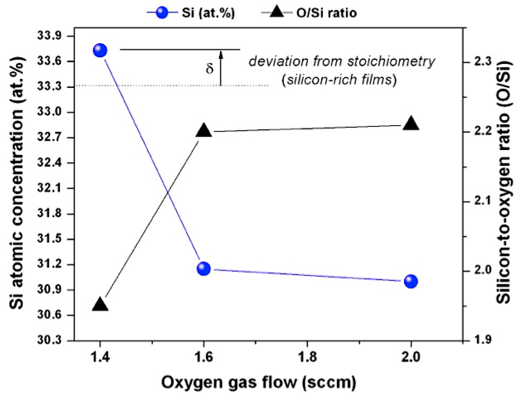
Figure 6 shows the evolution of Si atomic concentration (at %) for the as-deposited SiOx films as a function of the different O2 gas flows, which also includes the variation of the O/Si ratio.
According to Figure 6, it is possible to infer that the higher Si atomic concentration (low oxygen content) corresponds to sample deposited with 1.4 sccm of O2 gas flow and it diminishes rapidly when the reactive O2 gas flow is increased to 1.6 sccm. However, the Si atomic content practically does not change when the O2 flow rate is increased again to 20%. On the other hand, it is also observed that the films deposited under 1.6 sccm and 2.0 sccm of O2 gas flows have essentially the same O/Si ratio, denoting oxygen-rich SiOx films. For the films deposited with a reactive O2 gas flow of 1.4 sccm, the O/Si ratio is 1.95, thus involving oxygen-deficient films and lower Si oxidation state. These results are totally in agreement with the ones obtained by FTIR, since in the lower frequency-region of the FTIR spectra, the lower O/Si ratio also caused a shift in characteristic dipole-active vibration modes towards lower frequencies, as shown in Figure 3 and Table 2. Knowing the film’s thickness, the optical absorption coefficient α(λ) was determined from the transmittance measurements by using the relation [41],
α ( λ )   =   1 d ln [ ( 1     R ) 2 T ( λ ) ]
where λ is the wavelength of the of incident photon, T(λ) is the transmittance at a particular wavelength, R is the reflectance (R ≤ 5%) and d ≈ 500 nm is the thickness of the as-deposited SiOx films measured by SEM.
In non-crystalline SiO2, although there is no long-range order, its electronic structure is similar to the electronic structure of α-quartz, the crystalline form of SiO2. However, the absorption spectra, as in any disordered material, extend to energies well below the absorption threshold of the crystalline counterpart. Even though the so-called Tauc plot [42] may be used to determine a kind of band-gap energy by extrapolation, this parameter not always is quite meaningful because its value depends very much on the choice of the (limited) spectral range used for extrapolation. Experimentally, the sub-gap absorption in many disordered materials is known to obey the Urbach rule [23,43],
α ( λ )   =   α 0 exp [ σ ω     E g k B T ]
where α0 is a constant, ħ is the reduced Planck constant, Eg is an effective band-gap energy, ω = 2πc/λ is the frequency of the incident photon, kB is the Boltzmann constant, T is the temperature and σ is a dimensionless material parameter often called the steepness parameter. Note that the temperature dependence implies the participation of phonons [44]. The steepness parameter (σ) is connected with the Urbach energy (Eu) through the relation [45],
E u   =   k B T σ
This energy may be interpreted as the band tail width: It is weakly dependent on temperature and describes localized states that exist in the bandgap of disordered materials [43,46]. Both Eg and Eu are usually considered as fitting parameters in Equation (4) [47].
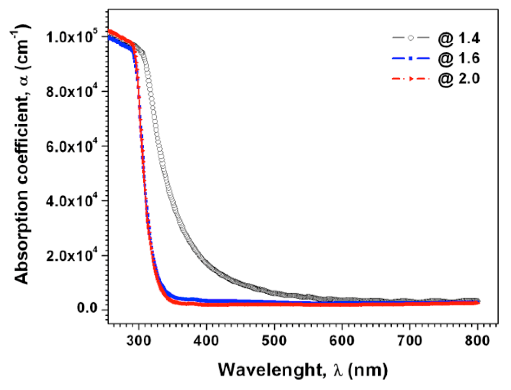
The dependence of the optical absorption coefficient, α(λ), of the produced SiOx thin films upon the incident photon wavelength is depicted in Figure 7.
The analysis of the figure shows that, for all samples, the value of the absorption coefficient decreases with the increase of the incident photon wavelength till to a certain value, from which it becomes almost invariant. It is also observed that the decrease of α(λ), is much more pronounced for the samples produced with the O2 gas flows of 1.6 and 2.0 sccm, whose spectra are essentially overlapped with each other. For these samples, the absorption edge is about 290 nm whereas for the sample identified as @1.4 (i.e., Si-rich sample) it is shifted to a higher wavelength (≈325 nm), thus suggesting a lower energy bandgap than for other two samples.
Figure 8 shows the plot of logα versus photon energy (ħω) in the range of the Urbach tail.
The value of Eu can be obtained from the reciprocal of the slope of the straight line of plotting logα against the incident photon energy. On the other hand, Eu can be possibly estimated as the position of the point where the exponential behavior of α (in normal scale, according to Equation (4)) changes to a slower (potential function) increase with ħω. This estimation is demonstrated in Figure 8 through representation with dashed vertical lines. Anyway, after fitting the Urbach absorption tails with Equation (4), the obtained values of the Urbach energy, the band-gap energy, the α0 constant and the steepness parameter (σ) are listed in Table 4.
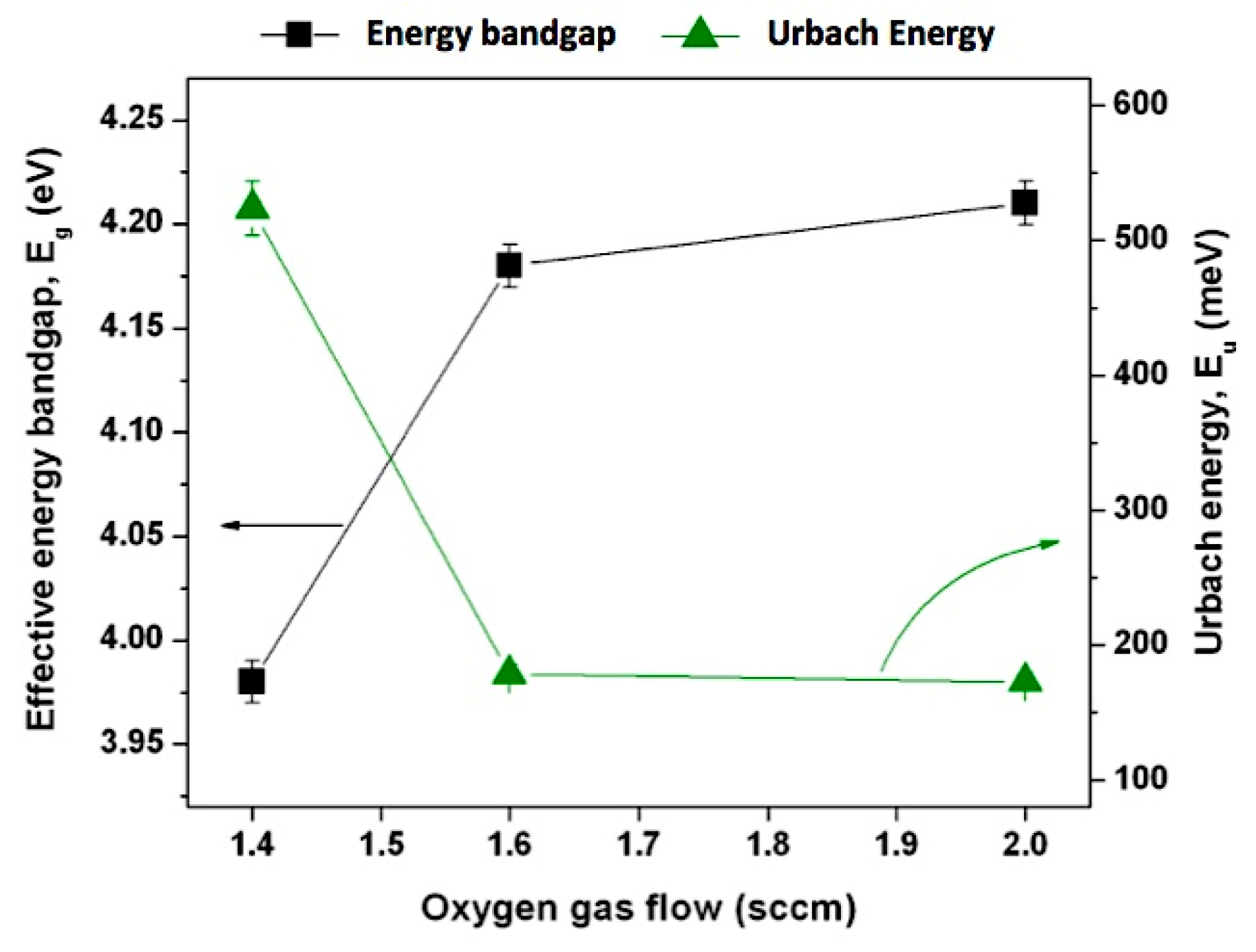
Figure 9 graphically compares the variation of Eu and Eg versus the O2 gas flow rate utilized in the fabrication of the SiOx thin films.
It can be observed that the Urbach energy comes opposite to the behavior of the energy bandgap. In fact, Figure 9 shows that the Eu value increased with the increase in the Si content (Si-rich SiOx films). This behavior can be explained and analyzed on the basis of Mott and Davis’s model [48,49] for disordered materials. The increase in the deviation from the stoichiometric structure (i.e., the increase of silicon content at the expenses of oxygen) may lead to the increase in the disorder and formation of some defects in the films, which could produce localized states in the material then resulting in the increment of the Eu value in the band structure and, consequently, the decreasing the Eg values for samples with higher Si content.
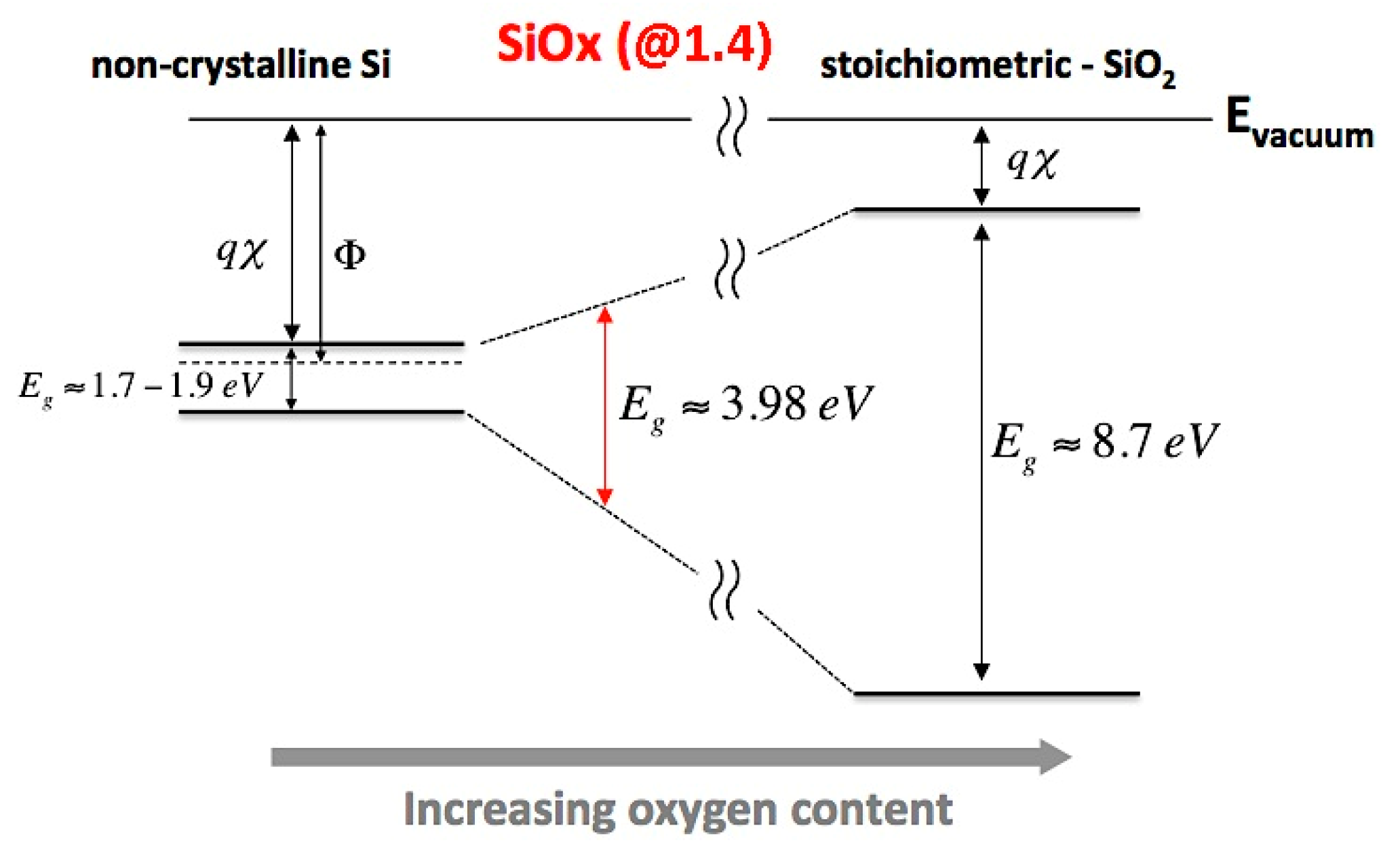
It is also important to note that for the sample deposited with the higher oxygen gas flow (2.0 sccm), the Eg value is far smaller than the well-established absorption edge in α-quartz, the crystalline form of SiO2, which occurs at ≈9 eV [50]. There are different opinions in the literature concerning details of the involved optical transitions. In one of the first calculations, Schulter and Chelikowsky [51] predicted a forbidden indirect lowest energy bandgap. However, in a subsequent computational work by Calabrese et al. [52], it was found that the band edge is direct forbidden (at ≈8.9 eV), followed by a direct allowed transition at ≈10.3 eV. Meanwhile, according to a recent review [47], the direct forbidden absorption edge of amorphous SiO2 (occurring in the K point) in terms of the Urbach model gives Eg ≈ 8.7 eV. Thus, the non-stoichiometric SiOx holds a wide bandgap that can be adjusted depending on the oxygen content. Starting at a bandgap of 1.7–1.9 eV for non-crystalline Si, the Eg value could theoretically be raised to ≈8.7 eV for stoichiometric SiO2 (see Figure 10).
For the SiOx coatings with x < 2 the valence band edge moves up, as the increased Si–Si bond states gradually overlap with the oxygen nonbonding states and lastly spread out into the Si valence band [50]. At the same time, the conduction band edge also moves down and, as a net result, a decrease in Eg is observed, as the Si concentration is gradually increased.
Butler and Ginley introduced a theoretical approach to estimate the position of band edges using the following relation [53,54],
E C B 0 =   E e X +   1 2 E g
where
X   =   [ x Si x x o y ] 1 x + y
and
x e l   =   1 2 ( A e l +   I e l ) ; e l   =   Si ,   O
Here E C B 0 is the conduction band potential, Ee is the energy of free electrons on the normal hydrogen electrode (NHE) scale (4.5 eV), X is the Sanderson electronegativity of the as-deposited material, which is dependent upon the elements of its composition, that is, X is expressed as the geometric mean of the electronegativities of the constituent atoms. On the other hand, the electronegativities of the constituent atoms are defined as the arithmetic mean of the atomic electron affinity energy, Ael, and the first ionization energy, Iel (both in eV) in which the “el” index refers to a particular chemical element. The values of the affinity energies for Si and O elements are 1.39 and 1.46 eV, respectively, while the ionization energies for these elements are 8.15 and 13.62 eV, respectively.
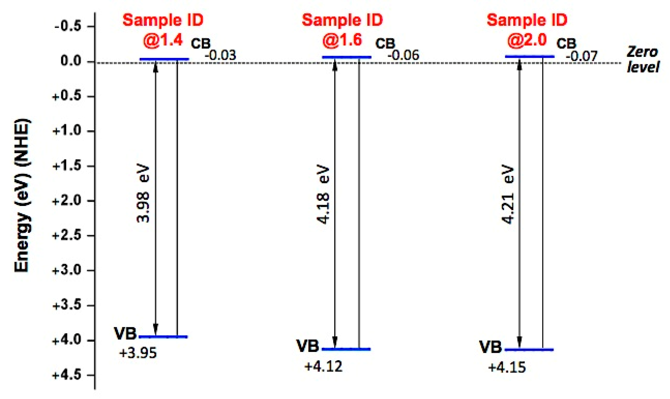
The calculated values of the Sanderson electronegativity, the positions of both the conduction band and the valence band ( E V B 0 ) of SiOx thin films (relative to the NHE scale) are shown in Table 5 and represented in Figure 11.
It is observed that the positions of the conduction band and valence band of the as-deposited SiOx thin films were shifted toward more negative and more positive potentials, respectively by increasing the ratio of the oxygen content of the SiOx films.
Figure 12 refers to the cross-section SEM micrograph of the sample identified as @1.4. It is noteworthy that in order to carry out SEM analysis, the SiOx films were firstly deposited on aluminium substrates. This procedure makes easier to visualize and distinguish the different interfaces formed by the as-deposited SiOx thin film and the Al underlying substrate.
From the analysis of SEM micrograph, it can be clearly observed that the as-deposited SiOx thin film exhibits great compactness (thus, also being an excellent solution in coating’ applications for gas diffusion barriers) and presents a high leveling ability, as it exhibits great thickness uniformity along all the surface of the underlying Al substrate.

3.3. Current–Voltage Characteristics

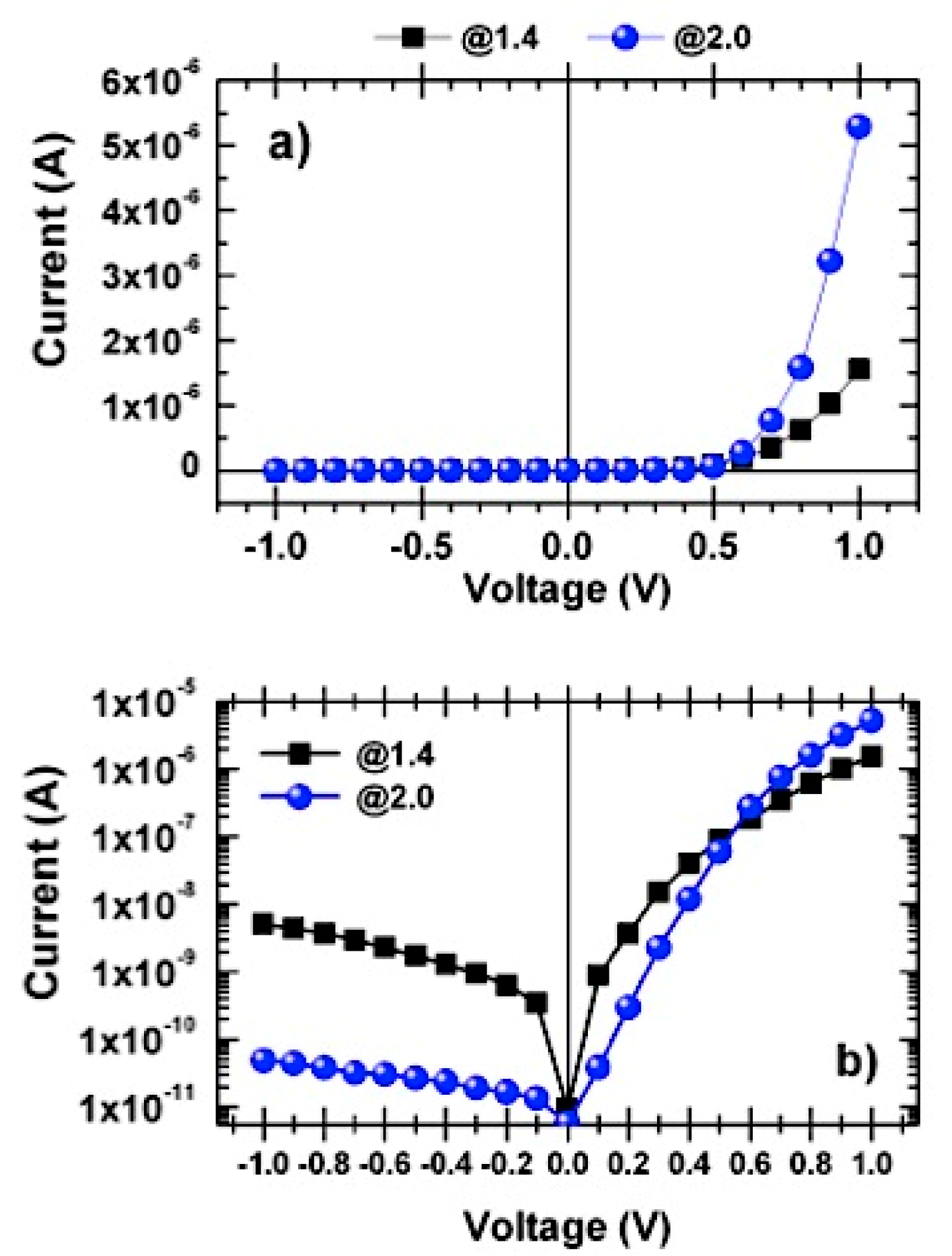
Figure 13 shows the I-V characteristic of the Au/SiOx/n-Si structure (MIS structure) in both linear (Figure 13a) and semi-logarithmic scale (Figure 13b), measured in dark and at room temperature (T ≈ 300 K, a typical situation in Portugal characterized by high average ambient temperature). The plots in Figure 13, refers to the samples deposited with O2 gas flows of 1.4 and 2.0 sccm and does not include the sample coded as @1.6 because, for this sample, the corresponding characteristic curve practically overlaps with that of sample @2.0, a situation already observed for the case of FTIR measurements and also in optical analysis.
It is observed that the Au/SiOx/n-Si structure (behaving like a Schottky diode) exhibits a very good diode rectifying performance with a rectification ratio of 300 and up to 104, which refer to the @1.4 and @2.0 samples, respectively. These values were calculated by taking the ratio of IF/IR at 1 V, where IF and IR stands for the forward and reverse current, respectively.
For both samples, the forward current increases exponentially (see Figure 13a) till reaching the series-resistance (RS) limited region, which is characterized by a descending curvature (see Figure 13b). It is well-known that for an ideal diode the standard I-V characteristic curve can be expressed by the thermionic emission model [55]
I ( V ) =   I 0 [ exp ( q V n k B T ) 1 ]
where V is the applied voltage, n is the ideality factor, q is the electron charge and I0 is reverse saturation current due to the minority carriers, which can be given by:
I 0 = S A * T 2 exp ( q φ b k B T )
where   q φ b is the apparent Schottky barrier height for zero-bias point at the interface, S is the area of the rectifier contact and A* is the effective Richardson constant.
The reverse current, IR, in Figure 13b (−1 < V < 0) V, provides valuable information about the device structure. As observed from Figure 13b the I-V curves quite differ from the linearity at high reverse bias voltage. The measured current values grow with the increase in reverse applied bias voltage and scale up gradually with the reverse bias without any influence of saturation for all the devices. In this case, non-saturating behavior of reverse current can be explained in terms of the image force lowering of the barrier height due to unstable O and H presence. Moreover, IR for the @1.4 sample is about two orders of magnitude greater than that for the @2.0 sample at −1 V. The measurements of IR values have been carried out under dark conditions, at room temperature, which may have been sufficient to promote the generation of thermal carriers, whose contribution for IR could differ from sample to sample and depends on the energy band characteristics. Noteworthy is that, in general, the higher values of reverse current were registered for sample @1.4, which is the one with the highest Urbach energy and the lowest bandgap value and also oxygen-deficient, thus eventually facilitating the excitation of charge carriers by thermal generation.
The equation that governs an ideal diode makes certain assumptions. Firstly, it assumes a low-level injection of carriers across the junction and also the resistance of the diode in different non-homogenous regions is neglected. However, for a real diode, a number of non-idealities are usually found and this should be taken into consideration to perform its characterization and the ideal diode equation is usually written in the form (9) with I0Iparts and nnparts, applied to a limited range of V.
Such a relation is the so-called by-parts diode equation and highlights that some particular mechanisms play a dominant role in certain regions of the diode’s I-V characteristic curve. For most of cases, it is usual to analyze two different regions in the real diode’s I-V characteristic curve, in which certain mechanisms dominate the current flow. These two regions are the designated by diffusion region (where the dominant current mechanism is a diffusion process) and the Ohmic depletion region, which in turn, plays a dominant role where the forward current flow already takes much higher values [56]. The majority of effects occurring in the Ohmic region (also known as the high injection level regime) arise from changes in the majority carrier concentrations on both sides of the diode’s depletion region.
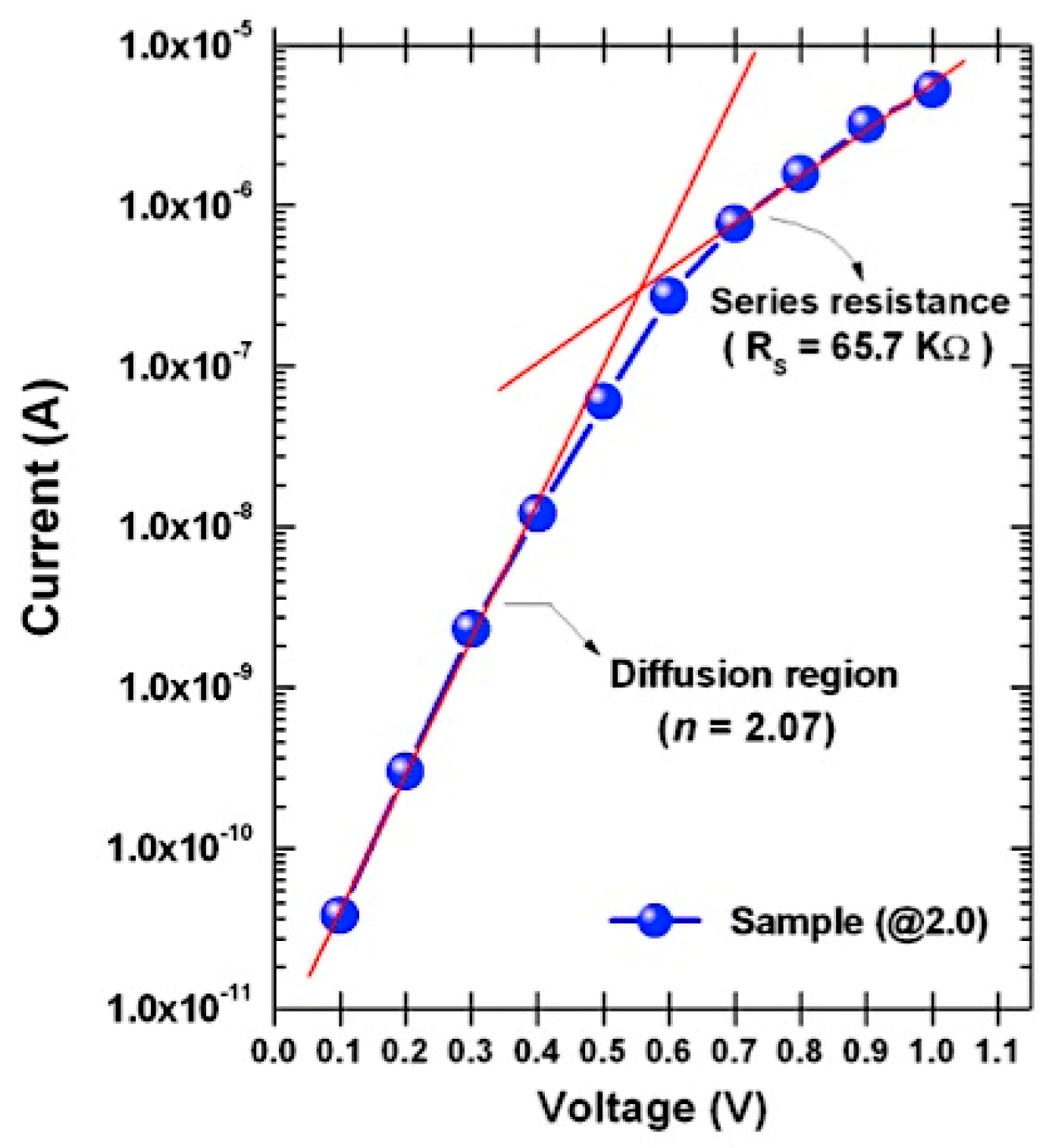
Thus, Iparts and nparts are characteristic values depending on the dominant mechanism the causing current flow in a real diode. It is important to refer that the ideality factor, nparts not only takes into account the different current flow mechanisms, but it also depends on unwanted defects eventually introduced at the SiOx/n-Si interface during the deposition process. According to Equation (9), the ideality factor of the Au/SiOx/n-Si structure was determined from the slope of the straight line taken in the diffusion region of the forward I-V characteristic curve plotted in the logarithmic scale, [qV/(nparts × kB × T)]. For the purpose of identifying the two abovementioned regions in an I-V characteristic curve of a real diode, Figure 14 shows the I-V characteristic for the forward-biased Au/SiOx/n-Si real diode referring to the sample identified as @2.0, which refers to the sample deposited with the higher O2 gas flow.
The series diode resistance, RS was determined by taking the reciprocal of the slope of the tangent to the corresponding I-V curve in the higher injection region, that is RS = (dI/dV)−1. Regarding the sample @2.0, the calculated values for the ideality factor and series diode resistance are 2.07 and 65.7 kΩ, respectively. For the sample @1.4 we have the values of n = 3.03 and RS ≈ 217 kΩ. Taking into account these findings (in particular, the excellent value of the ideality factor for sample @2.0), it is possible to state that the O2 gas flow has a crucial influence on the rectifying performance of the produced Au/SiOx/n-Si Schottky diodes since, both n and RS decrease with the growth of the oxygen content. It possibly reflects a closer approximation to the full stoichiometric condition. The increase of both n and RS of sample @1.4 may suggest eventual changes in the diffusion mechanism of charge carriers, which may be due to the presence of a greater number of defects and disorder in the SiOx/n-Si interface formed during the deposition process as well as some eventual contribution of the I-V setup employed. The high n values can also be the indication of the presence of an interfacial insulator layer patches at Au/SiOx interface or wide distribution of low Schottky barrier heights and distribution of interface states at the device interface.

4. Conclusions

A set of SiOx thin films were deposited by means of the target voltage control method, a simple procedure of reactive pulsed DC magnetron sputtering (PMS) at three different reactive gas (O2) flow rates. The use of the lowest O2 flow (@1.4) produced Si-rich thin films, while increasing the O2 gas flow facilitated the deposition of oxygen-rich films approaching stoichiometry (SiO2) as proven by IR absorption spectra. The results further suggest that it was the bombardment of the target with O2 gas that promoted a change in the oxidation state of the films being deposited, from silicon excess to a more stoichiometric structure, with Si–O bonds progressively replacing Si–Si bonds. Extending the FTIR spectra to the high-frequency region reveals the presence of H2O (O–H stretching vibrations) associated with the deposition and attributed to desorbed water from the walls of the vacuum chamber. The presence of H2O acts as an additional and contaminating source of hydrogen atoms, which possibly compete with the reactive O2 gas to form bonds with the silicon atoms that have been sputtered by Ar+ ion bombardment. In a future project, our deposition chamber will be improved by external application (along the entire diameter of its cylindrical body) of a thermal strap to prevent further contamination with unwanted water vapor.
The dependence of the film’s optical characteristics, namely the Urbach energy and energy bandgap, upon the oxygen content was demonstrated, since the lower O2 flow (@1.4) was proven to produce a Si-rich material with a larger Urbach tail and a narrower optical bandgap. It can be associated to the presence of more defects and a greater degree of disorder, which probably arises from an additional contamination source due to the presence of water vapor in the vacuum chamber during the deposition process.
Moreover, it is observed that the Au/SiOx/n-Si structure exhibits a Schottky diode rectifying behavior with a rectification ratio of about two orders of magnitude, between @1.4 and @2.0 samples, suggesting the device interface to be relatively free of interface states. Additionally, the above results have confirmed, that the PMS is a useful deposition method for SiO2 and the deposited thin film characteristics depend primarily on the O2 gas flow rate. Therefore, in a future article, the entire range of the O2 flow ratios shown in Figure 2 will be used to cover all the different deposition modes in order to study additional properties related to interlayers and barrier diffusion of SiOx thin films included under the scope of an on-going project.

Author Contributions

Conceptualization, J.O.C., V.T., M.F.C. and A.P.S.; Methodology, J.O.C., M.I.V., L.R., V.T., M.F.C. and A.P.S; Software, F.M.; Validation, J.O.C., M.I.V, V.T., M.F.C., S.L.M, L.R. and A.P.S.; Formal Analysis, J.O.C., M.I.V., M.F.C. and S.L.M.; Investigation, J.O.C., F.M., M.I.V, M.F.C., S.L.M, L.R. and A.P.S.; Resources, J.O.C., M.I.V, S.L.M, L.R. and V.T.; Data Curation, J.O.C., F.M. and A.P.S.; Writing—Original Draft Preparation, J.O.C.; Writing—Review and Editing, J.O.C., M.I.V, V.T., M.F.C., F.M. and A.P.S.; Visualization, F.M.; Supervision, J.O.C., M.I.V, S.L.M, L.R. and V.T.; Project Administration, J.O.C.; Funding Acquisition, J.O.C., M.I.V, S.L.M, L.R. and V.T.

Funding

This work was supported by the Portuguese Foundation for Science and Technology (FCT) in the framework of the Strategic Funding UID/FIS/04650/2019.

Conflicts of Interest

The authors declare no conflict of interest.

References

  1. López, J.A.L.; Valerdi, D.E.V.; Lara, A.B.; Salgado, G.G.; Hernández-de la Luz, A.D.; Sánchez, A.M.; Flores Gracia, F.J.; Dominguez, M.A. Optical and compositional properties of SiOx films deposited by HFCVD: Effect of the hydrogen flow. J. Electron. Mater. 2017, 46, 2309. [Google Scholar] [CrossRef]
  2. Liao, N.; Xue, W.; Zhou, H.; Zhang, M. Investigation on high temperature fracture properties of amorphous silicon dioxide by large-scale atomistic simulations. J. Mater. Sci. Mater. Electron. 2013, 24, 1575–1579. [Google Scholar] [CrossRef]
  3. Jiew, C.; Chien, Y.; Yung, R. Development of a robust 2T-SONOS cell for embedded flash application. In Proceedings of the Non-Volatile Memory Technology Symposium (NVMTS, 12), Singapore, 31 October–2 November 2012; pp. 1–6. [Google Scholar]
  4. Leterrier, Y. Durability of nanosized oxygen-barrier coatings on polymers—Internal stresses. Prog. Mater. Sci. 2003, 48, 1–55. [Google Scholar] [CrossRef]
  5. Dennler, G.; Houdayer, A.; Segui, Y.; Wertheimer, M.R. Growth and structure of hyperthin SiO2 coatings on polymers. J. Vac. Sci. Technol. A 2001, 19, 2320–2327. [Google Scholar] [CrossRef]
  6. Madou, M.J. Fundamentals of Microfabrication: The Science of Miniaturization, 2nd ed.; CRC Press LCC: Boca Raton, FL, USA, 2002. [Google Scholar]
  7. Nicollian, E.H.; Brews, J.R. MOS (Metal Oxide Semiconductor) Physics and Technology; Wiley: New York, NY, USA, 1982. [Google Scholar]
  8. Nakano, Y.; Jimbo, T. Electrical characterization of SiO2/n-GaN metal–insulator–semiconductor diodes. J. Vac. Sci. Technol. B Microelectron. Nanometer Struct. 2003, 21, 1364–1368. [Google Scholar] [CrossRef]
  9. Fedder, G.K. Mems fabrication. In Proceedings of the 2003 International Test Conference (ITC 2003): Breaking Test Interface Bottlenecks, Charlotte, NC, USA, 28 September–3 October 2003; Volume 1, pp. 691–698. [Google Scholar]
  10. Wright, J.T.; Carbaugh, D.J.; Haggerty, M.; Richard, A.L.; Ingram, D.C.; Jadwisienczak, W.M.; Rahman, F.; Kaya, S. Thermal oxidation of silicon in a residual oxygen atmosphere—The RESOX process—For self-limiting growth of thin silicon dioxide films. Semicond. Sci. Technol. 2016, 31, 105007. [Google Scholar] [CrossRef]
  11. Adams, A.C.; Smith, T.E.; Chang, C.C. The growth and characterization of very thin silicon dioxide films. J. Electrochem. Soc. 1980, 127, 1787–1794. [Google Scholar] [CrossRef]
  12. Boyd, I.W.; Wilson, J.I. A study of thin silicon dioxide films using infrared absorption techniques. J. Appl. Phys. 1982, 53, 4166–4172. [Google Scholar] [CrossRef]
  13. Jun, S.I.; McKnight, T.E.; Melechko, A.V.; Simpson, M.L.; Rack, P.D. Characterisation of reactively sputtered silicon oxide for thin-film transistor fabrication. Electron. Lett. 2005, 41, 822–823. [Google Scholar] [CrossRef]
  14. Carneiro, J.; Teixeira, V.; Martins, A.; Mendes, M.; Ribeiro, M.; Vieira, A.; Carneiro, J. Surface properties of doped and undoped TiO2 thin films deposited by magnetron sputtering. Vacuum 2009, 83, 1303–1306. [Google Scholar] [CrossRef]
  15. Sainty, W.G.; Netterfield, R.P.; Martin, P.J. Protective dielectric coatings produced by ion-assisted deposition. Appl. Opt. 1984, 23, 1116–1119. [Google Scholar] [CrossRef] [PubMed]
  16. Alvisi, M.; De Tomasi, F.; Della Patria, A.; Di Giulio, M.; Masetti, E.; Perrone, M.R.; Protopapa, M.L.; Tepore, A. Ion assistance effects on electron beam deposited MgF2 films. J. Vac. Sci. Technol. A 2002, 20, 714–720. [Google Scholar] [CrossRef]
  17. Jaing, C.-C.; Shiao, M.-H.; Lee, C.-C.; Lu, C.-J.; Liu, M.-C.; Lee, C.-H.; Chen, H.-C. Effects of ion assistance and substrate temperature on optical characteristics and microstructure of MgF2 films formed by electron-beam evaporation. Jpn. J. Appl. Phys. 2006, 45, 5027–5029. [Google Scholar] [CrossRef]
  18. Megiris, C.E.; Glezer, J.H.E. Preparation of silicon dioxide films by low-pressure chemical vapor deposition on dense and porous alumina substrates. Chem. Eng. Sci. 1992, 47, 3925–3934. [Google Scholar] [CrossRef]
  19. Hayashi, S.; Tanimoto, S.; Yamamoto, K. Analysis of surface oxides of gas-evaporated Si small particles with infrared spectroscopy, high-resolution electron microscopy, and x-ray photoemission spectroscopy. J. Appl. Phys. 1990, 68, 5300–5308. [Google Scholar] [CrossRef]
  20. Teixeira, V.; Soares, P.; Martins, A.J.; Carneiro, J.; Cerqueira, F.; Cerqueira, M.F. Nanocomposite metal amorphous-carbon thin films deposited by hybrid PVD and PECVD technique. J. Nanosci. Nanotechnol. 2009, 9, 4061–4066. [Google Scholar] [CrossRef] [PubMed]
  21. Sellers, J. Asymmetric bipolar pulsed DC: The enabling technology for reactive PVD. Surf. Coat. Technol. 1998, 98, 1245–1250. [Google Scholar] [CrossRef]
  22. Kelly, P.; Beevers, C.; Henderson, P.; Arnell, R.; Bradley, J.; Bäcker, H. A comparison of the properties of titanium-based films produced by pulsed and continuous DC magnetron sputtering. Surf. Coat. Technol. 2003, 174, 795–800. [Google Scholar] [CrossRef]
  23. Studenyak, I.; Kranjčec, M.; Kurik, M. Urbach rule in solid state physics. Int. J. Opt. Appl. 2014, 4, 76–83. [Google Scholar]
  24. Schottky, W. Zur Halbleitertheorie der Sperrschicht- und Spitzengleichrichter. Z. Phys. 1939, 113, 367–414. [Google Scholar] [CrossRef]
  25. Tung, R.T. The physics and chemistry of the Schottky barrier height. Appl. Phys. Rev. 2014, 1, 011304. [Google Scholar] [Green Version]
  26. Zhang, Z.; Yates, J.T., Jr. Band bending in semiconductors: Chemical and physical consequences at surfaces and interfaces. Chem. Rev. 2012, 112, 5520–5551. [Google Scholar] [CrossRef] [PubMed]
  27. Carneiro, J.; Teixeira, V.; Portinha, A.; Magalhães, A.; Coutinho, P.; Tavares, C.J.; Newton, R.; Carneiro, J.; Magalhaẽs, A. Iron-doped photocatalytic TiO2 sputtered coatings on plastics for self-cleaning applications. Mater. Sci. Eng. B 2007, 138, 144–150. [Google Scholar] [CrossRef]
  28. Carneiro, J.O.; Teixeira, V.; Nascimento, J.H.O.; Neves, J.; Tavares, P.B.; Carneiro, J. Photocatalytic activity and UV-protection of TiO2 nanocoatings on poly(lactic acid) fibres deposited by pulsed magnetron sputtering. J. Nanosci. Nanotechnol. 2011, 11, 8979–8985. [Google Scholar] [CrossRef] [PubMed]
  29. Barradas, N.; Jeynes, C.; Webb, R.; Kreissig, U.; Grötzschel, R. Unambiguous automatic evaluation of multiple ion beam analysis data with simulated annealing. Nucl. Instrum. Methods Phys. Res. Sect. B Beam Interact. Mater. At. 1999, 149, 233–237. [Google Scholar] [CrossRef]
  30. Musil, J.; Baroch, P.; Vlček, J.; Nam, K.; Han, J. Reactive magnetron sputtering of thin films: Present status and trends. Thin Solid Film. 2005, 475, 208–218. [Google Scholar] [CrossRef]
  31. Ohring, M. The Materials Science of Thin Films; Academic Press: San Diego, CA, USA, 1991. [Google Scholar]
  32. Sigmund, P. Theory of sputtering. I. Sputtering yield of amorphous and polycrystalline targets. Phys. Rev. 1969, 184, 383. [Google Scholar] [CrossRef]
  33. Kudriavtsev, Y.; Villegas, A.; Godines, A.; Asomoza, R. Calculation of the surface binding energy for ion sputtered particles. Appl. Surf. Sci. 2005, 239, 273–278. [Google Scholar] [CrossRef]
  34. Ay, F.; Aydinly, A. Comparative investigation of hydrogen bonding in silicon based PECVD grown dielectrics for optical waveguides. Opt. Mater. 2004, 26, 33–46. [Google Scholar] [CrossRef] [Green Version]
  35. Lin, G.-R.; Lin, C.-J.; Lin, C.-K.; Chou, L.-J.; Chueh, Y.-L. Oxygen defect and Si nanocrystal dependent white-light and near-infrared electroluminescence of Si-implanted and plasma-enhanced chemical-vapor deposition-grown Si-rich SiO2. J. Appl. Phys. 2005, 97, 094306. [Google Scholar] [CrossRef]
  36. Pai, P.G.; Chao, S.S.; Takagi, Y.; Lucovsky, G. Infrared spectroscopic study of silicon oxide (SiOx) films produced by plasma enhanced chemical vapor deposition. J. Vac. Sci. Technol. A 1986, 4, 689–694. [Google Scholar] [CrossRef]
  37. Vázquez-Valerdi, D.E.; Luna-López, J.A.; Carrillo-López, J.; García-Salgado, G.; Benítez-Lara, A.; Espinosa-Torres, N.D. Compositional and optical properties of SiOx films and (SiOx/SiOy) junctions deposited by HFCVD. Nanoscale Res. Lett. 2014, 9, 422. [Google Scholar] [CrossRef] [PubMed]
  38. Morioka, T.; Tsuda, N.; Koike, C.; Kaito, C.; Saito, Y.; Kimura, S. Study of the structure of silica film by infrared spectroscopy and electron diffraction analyses. Mon. Not. R. Astron. Soc. 1998, 299, 78–82. [Google Scholar] [CrossRef]
  39. Ogata, Y.; Niki, H.; Sakka, T.; Iwasaki, M. Oxidation of porous silicon under water vapor environment. J. Electrochem. Soc. 1995, 142, 1595–1601. [Google Scholar] [CrossRef]
  40. Gupta, P.; Dillon, A.; Bracker, A.; George, S. FTIR studies of H2O and D2O decomposition on porous silicon surfaces. Surf. Sci. 1991, 245, 360–372. [Google Scholar] [CrossRef]
  41. Hassanien, A.S.; Akl, A.A. Influence of composition on optical and dispersion parameters of thermally evaporated non-crystalline Cd50S50-xSex thin films. J. Alloys Compd. 2015, 648, 280–290. [Google Scholar] [CrossRef]
  42. Tauc, J.; Grigorovici, R.; Vancu, A. Optical Properties and electronic structure of amorphous germanium. Phys. Status Solidi 1966, 15, 627–637. [Google Scholar] [CrossRef]
  43. Urbach, F. The long-wavelength edge of photographic sensitivity and of the electronic absorption of solids. Phys. Rev. 1953, 92, 1324. [Google Scholar] [CrossRef]
  44. Malainho, E.; Vasilevskiy, M.I.; Alpuim, P.; Filonovich, S.A. Dielectric function of hydrogenated amorphous silicon near the optical absorption edge. J. Appl. Phys. 2009, 106, 073110. [Google Scholar] [CrossRef]
  45. Hassanien, A.S.; Akl, A.A. Effect of Se addition on optical and electrical properties of chalcogenide CdSSe thin films. Superlattices Microstruct. 2016, 89, 153–169. [Google Scholar] [CrossRef]
  46. Kazmersky, L.L. (Ed.) Polycrystalline and Amorphous Thin Films and Devices; Academic Press: New York, NY, USA, 1980; p. 135. [Google Scholar]
  47. Nekrashevich, S.S.; Gritsenko, V.A. Electronic structure of silicon dioxide (a review). Phys. Solid State 2014, 56, 207–222. [Google Scholar] [CrossRef]
  48. Mott, N.F.; Davis, E.A. Electronic Processes in Non-Crystalline Materials; Oxford University Press: Oxford, UK, 1971. [Google Scholar]
  49. Fadel, M.; Fayek, S.; Abou-Helal, M.; Ibrahim, M.; Shakra, A. Structural and optical properties of SeGe and SeGeX (X = In, Sb and Bi) amorphous films. J. Alloys Compd. 2009, 485, 604–609. [Google Scholar] [CrossRef]
  50. Choi, Y.-R.; Zheng, M.; Bai, F.; Liu, J.; Tok, E.-S.; Huang, Z.; Sow, C.-H. Laser-induced greenish-blue photoluminescence of mesoporous silicon nanowires. Sci. Rep. 2014, 4, 4940. [Google Scholar] [CrossRef] [PubMed]
  51. Schlüter, M.; Chelikowsky, J. Electron states in α-quartz (SiO2). Solid State Commun. 1977, 21, 381–384. [Google Scholar] [CrossRef]
  52. Calabrese, E.; Fowler, W.B. Electronic energy-band structure of α quartz. Phys. Rev. B 1978, 18, 2888–2896. [Google Scholar] [CrossRef]
  53. Butler, M.A. Prediction of flatband potentials at semiconductor-electrolyte interfaces from atomic electronegativities. J. Electrochem. Soc. 1978, 125, 228–232. [Google Scholar] [CrossRef]
  54. Morrison, S.R. Electrochemistry at Semiconductor and Oxidized Metal Electrodes; Plenum Press: New York, NY, USA, 1980. [Google Scholar]
  55. Chen, X.Y.; Lu, Y.F.; Tang, L.J.; Wu, Y.H.; Cho, B.J.; Xu, X.J.; Dong, J.R.; Song, W.D. Annealing and oxidation of silicon oxide films prepared by plasma-enhanced chemical vapor deposition. J. Appl. Phys. 2005, 97, 014913. [Google Scholar] [CrossRef] [Green Version]
  56. Bo, H.; Ma, Z.Q.; Jing, X.; Lei, Z.; Sheng, Z.N.; Feng, L.; Cheng, S.; Ling, S.; Jie, M.X.; Yue, Z.C.; et al. Structural, electrical and optical properties of AZO/SiO2/p-Si SIS heterojunction prepared by magnetron sputtering. Opt. Appl. 2010, 40, 15–24. [Google Scholar]
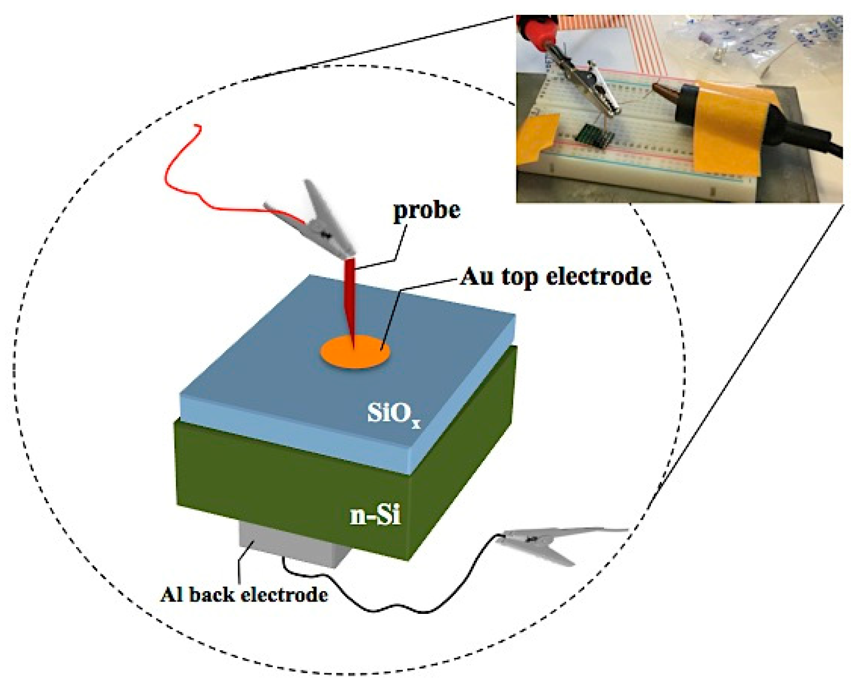
Figure 1. Experimental set-up for measuring of I-V characteristics and schematic representation of Au/SiOx/n-Si structure.
Coatings 09 00468 g001
Figure 2. Hysteresis behaviors of target (cathode) voltage as a function of reactive O2 gas flow rate.
Coatings 09 00468 g002
Figure 3. Fourier-transform infrared (FTIR) spectra for the as-deposited SiOx films and also for stoichiometric SiO2 (silica powder). δ is the deviation from stoichiometry.
Coatings 09 00468 g003
Figure 4. Spectra acquired in high-frequency range for the as-deposited SiOx films (a) and structural geometries of the different oxidized states (b).
Coatings 09 00468 g004
Figure 5. Rutherford backscattering spectrometry (RBS) spectrum of a SiOx layer (for sample @1.4). Arrows specify surface peaks of O, Si, and Ar.
Coatings 09 00468 g005
Figure 6. Si atomic concentration (at %) and O/Si ratio measured by RBS as a function of the O2 gas flow.
Coatings 09 00468 g006
Figure 7. The variation of the optical absorption coefficient for different SiOx thin films.
Coatings 09 00468 g007
Figure 8. The variation of logα with the incident photon energy (ħω), from which the Urbach energy for SiOx thin films was obtained.
Coatings 09 00468 g008
Figure 9. Variation of the Urbach energy and bandgap energy as a function of O2 gas flow for the as-deposited SiOx films.
Coatings 09 00468 g009
Figure 10. Variation of the bandgap energy from 1.7–1.9 eV for a-Si to about 8.7 eV for stoichiometric SiO2, controlled by varying the oxygen concentration (here, is the electron affinity and Φ is the electron work function).
Coatings 09 00468 g010
Figure 11. The conduction and valence band energy potentials of the SiOx thin films.
Coatings 09 00468 g011
Figure 12. Cross-section SEM micrograph referring to the @1.4 SiOx sample deposited on Al substrate.
Coatings 09 00468 g012
Figure 13. Current–voltage characteristic curve of Au/SiOx/n-Si structure in dark. Linear (a) and semi-logarithmic (b) scale.
Coatings 09 00468 g013
Figure 14. I-V characteristic curve for the forward-biased Au/SiOx/n-Si real diode (@2.0 sample).
Coatings 09 00468 g014
Table 1. Parameters used in pulsed direct current (DC) magnetron sputtering of SiOx thin films.
Sample IDCurrent (A)Voltage (V)Reverse Time (µs)Frequency (kHz)Gas Flow (sccm)Reverse Phase (%)
ArO2
@1.40.353855.060.08.01.430.0
@1.62171.6
@2.02102.0
Table 2. FTIR vibration modes for as-deposited SiOx films [34,35,36].
Vibration ModePeak Position (cm−1)
Sample ID
@1.4@1.6@2.0SiO2
Si–O rocking397438440461
Si–O bending789797799810
Si–O stretching (on phase)932101010131082
Si–O stretching out of phase1140114811501203
Si–H wagging648
Table 3. Frequencies and type of vibrations modes in high-frequency range for the as-deposited thin films [39].
GroupClusterPeak NumberVibration TypeWavenumber (cm−1)
SiH3OSiH3(3)s-stretching2162
SiH2OSiH2(2)a-stretching2025
SiHOSiH(1)stretching1980
O2SiH(4)stretching2376
Table 4. The values of the Urbach energy (Eu), direct forbidden bandgap energy (Eg), steepness parameter (σ) and the pre-exponential constant (α0) for the as-deposited SiOx thin films.
Sample IDEu (meV)Eg (eV)Steepness Parameter (σ)Constant, α0 (cm−1)
@1.4523.453.980.049104.1
@1.6178.484.180.145104.8
@2.0172.854.210.150105.1
Table 5. The values of the optical energy bandgap (Eg), the Sanderson electronegativity (X) and the positions of both the conduction and valence bands (relative to the normal hydrogen electrode (NHE) scale) for the produced SiOx thin films.
Sample IDEg (eV)X (eV) E C B 0   ( eV )
(vs. NHE Scale)
E V B 0   ( eV )
(vs. NHE Scale)
@1.43.986.457−0.033.95
@1.64.186.534−0.064.12
@2.04.216.539−0.074.15