1. Introduction
The modern advancements in the automotive, aerospace, medical, and optoelectronic industries require the development of new types of coatings with high mechanical, thermal, and magnetic properties. For example, steel components and parts can be protected from oxidation, physical stress, and corrosion by applying high-quality metallic coatings that have more desirable properties. Such metal coatings include, protective coatings to provide corrosion resistance; protective/decorative coatings, which serve anticorrosion and decorative purposes; and other special coatings, which provide increased hardness, wear resistance, antifriction properties, thermal and light reflectivity, etc. [
1].
Aluminium coatings are widely used in the industry to provide corrosion protection and reflect light and heat. It has been shown that an aluminium coating only a couple micrometres thick can protect steel better than widely used cadmium and chromate coatings that were tens of micrometres thick [
2].
The physical vapour deposition (PVD) process in combination with various modern techniques for evaporating metals has outstanding potential for forming relatively dense and smooth anticorrosion coatings. It has been reported that a coating of aluminium applied to steel using PVD provides ten times more corrosion resistance than a zinc coating applied using hot-dip galvanising or electroplating [
3]. Further, various combinations of alloyed or layered materials can be deposited from the vapour phase, thus expanding the possibilities for PVD of coatings that provide mechanical protection against damage, during mechanical processing or wear over time, as well as chemical protection against corrosion or oxidation [
4,
5].
In the process of depositing aluminium coatings on hot-rolled steel, the coating thickness must be controlled. This is generally a challenge for both producers of rolled steel and consumers of the finished product. Spot measurements of the coating thickness can be performed by an operator on the line, using portable coating thickness analyzer (CTA) or on randomly selected samples in a laboratory. Usually, such portable CTAs are based on eddy currents, magnetic induction, or beta scattering [
6,
7,
8]. On the other hand, in manufacturing laboratories, X-ray fluorescence (XRF), which was first proposed by Helmut Fischer GmbH in 1953 [
9], is used to measure coating thicknesses.
In the XRF approach, the coating material is excited by an X-ray tube, and the characteristic secondary radiation emitted by the coating material is measured using an X-ray detector. The intensity of the emitted secondary radiation is directly proportional to the thickness in thin films and has an exponential relationship with thickness in thicker films, eventually reaching an upper limit as the thickness increases further. Using XRF analysis, the range of coating thicknesses that can be measured varies from nanometres to several tens of micrometres, depending on the type of film [
10] for the spot area from 0.2 to 5.0 cm
2. The accuracy of XRF thickness measurements for XRPA coatings in the laboratory has been reported as ±(2 ÷ 5)%.
To enable online process control, we previously developed an online industrial XRF CTA [
11]. It was demonstrated to conduct accurate thickness measurements of phosphate coatings on steel. However, XRF-based thickness measurements of coatings, composed of light elements with atomic numbers in the range of 11 to 20 (such as Mg, Al, Si), are difficult because such elements with atomic numbers below 20 emit X-ray photons that are easily absorbed by air. Thus, the X-ray detectors cannot register the emitted X-ray signals under normal industrial conditions. Thus, such measurements must be performed in a vacuum.
Hence, in this study, we propose the use of a vacuum measuring chamber to solve the problem of registration for light elements. Here we propose a novel system that addresses the complex technical and technological problems associated with the integration of the measuring head into the PVD system. We further demonstrate the accuracy and precision of the industrial XRF CTA for coatings of a representative light element, aluminium, deposited by PVD on rolled steel.
2. Design of the Coating Thickness Analyzer
The developed industrial online CTA includes, a measuring vacuum chamber; a measuring head, built-in to vacuum chamber; an external electronics unit (including the standard set of electronic devices for such equipment [
12]); and a software package that carries out the calculations to determine the coating thickness and transfer all data to the upper level of the enterprise management system.
One of the vacuum chambers included in the PVD production line was used for the XRF measurements. A steel strip with a width of 350–550 mm and thickness of 0.10–0.75 mm with an aluminium layer deposited on it (thickness ranging from 1 to 10 µm) was passed through this vacuum chamber at a speed of 2–200 m/min. The temperature of the measured steel strip can vary in the range from 100 to 250 °C. The wall of the vacuum chamber is contained a sealed flange that allows the measuring head to be inserted into the chamber.
The cylindrical measuring unit contains an X-ray tube with a Mo anode (maximum voltage 20 kV and power 50 W) and an X-ray detector (SDD with an area of 25 mm2, full width at half maximum of 140–160 eV at 5.9 keV and signal-to-noise ratio of 20,000). To ensure the stability of the parameters of primary excitation and to improve measurement precision, a low-voltage X-ray tube, with an end window, was used. Low voltage (<20 kV) and high current (up to 3 mA) were applied to the anode to provide optimal conditions to excite the Al Kα line, thereby ensuring the maximum fluorescence yield of X-ray photons from the aluminium coating.
The infrared radiation emitted by the hot technological strip resulted in high temperatures in the working vacuum chamber. Therefore, a special cooling system was needed to protect the components of the measuring head (both the X-ray tube and X-ray detector) from overheating and ensure thermal stabilisation inside the measuring unit. A water-cooling system, by which the water temperature was maintained by an industrial chiller, was installed in the measuring unit holder. This cooling system made it possible to measure the thicknesses of light-metal coatings on a metal substrate (steel) under vacuum and in elevated temperature conditions.
An accurate online analysis of the coating thickness was possible only where the measurement results were not affected by changes in the external conditions, such as the temperature of the material and environment, the uniformity and smoothness of the strip surface, defects in the surface, strip vibration amplitude, and the distance between the measuring head and the surface. Hence, when developing the CTA system and software, these features of the application were taken into account to reduce or compensate for the influence of these parameters.
The system collects thickness measurements from the coating in the centre of the steel strip as it moves through the process vacuum chamber. In this application, the XRF measuring head is fixed under the metal strip at a distance in the range of 40–80 mm, which makes it possible to decrease both the infrared radiation intensity (to some extent) and the influence of the distance and flatness changes, which can affect the measurement accuracy.
The ThMeter_AM thickness analyzer software is designed to operate in two modes: automatic and manual. Automatic mode provides continuous measurements of the coating thickness, which are saved and transferred to an upper-level control system. Manual mode can be used while setting up the spectrometer equipment, calibrating the instruments and designing new methods for thickness measurements. The software utilises a Pascal (script) to determine the thickness of the coating, T, from the measured intensity, I, according to a function T = f (I). This function can be changed by the operator during the calibration stage. In software, the coefficients for the approximating functions are calculated by the least-squares method.
Data exchange between the program and the upper-level control system is implemented using the OPC-DA protocol (OPC client). In automatic mode, the program using the OPC-DA protocol transmits the value of the measured coating thickness and the state of the spectrometer equipment to the upper level. All results are stored in a database. To ensure safety, the top-level control unit using the OPC-DA protocol can immediately turn off the power to the X-ray tube or prevent it from being turned on.
An additional feature is that the CTA is equipped with a standalone quality control (QC) device to ensure and verify the stability and reliability of the online measurements in real-time. The device was equipped with a specially designed holder with four control samples with coatings of known thickness. The holder was built into the vacuum chamber with a sealed flange in the camera body; it was located in the immediate vicinity of the steel strip without touching it. With the help of this device, QC measurements can be performed periodically under the same conditions as the online thickness measurements; the QC process can be initiated from the control room. The control samples can be changed either manually or automatically (depending on technical requirements) by gradually rotating the holder to move a different sample in front of the measuring head.
All these features provide the ability to measure the thickness of coatings of light metals (single-component layers of silicon, aluminium or magnesium or combinations of these elements with other elements) on a metal substrate (such as steel).
3. Laboratory Testing and Alalyser Calibration
Laboratory tests of the developed CTA were carried out to calibrate the CTA, characterise its performance and verify its compliance with customer requirements. The laboratory tests also included developing methods that achieve the required accuracy, selecting the appropriate measurement modes and determining the working range of thicknesses that can be measured. The procedures were carried out in accordance with those used to develop online conveyor analyzers for the mining industry [
12,
13].
The industrial vacuum chamber located on the customer’s technological line was replaced with a laboratory measuring vacuum chamber that was developed and manufactured to be suitable for measuring under the conditions close to real industrial. The laboratory chamber is shown in
Figure 1.
A supporting cylinder (5) is built into the steel hermetic chamber housing (1) via a flange. A measuring head (2) is hermetically attached to the end of the cylinder; it contains an X-ray tube and X-ray detector. To simulate real conditions for thickness measurements of coated samples (3), the laboratory measuring chamber of the CTA was equipped with a vacuum pump connected to the nozzle (4) and heated by a flexible heater. The temperature and vacuum in the measuring chamber were set to mimic the actual industrial conditions.
3.1. Calibration Samples and Measurement Conditions
The calibration standards with aluminium coating were tested in the laboratory to calibrate the system and validate the applicability of the CTA, in order to obtain reliable measurements in industry applications. Thirteen square steel plates (10 × 10 cm2) with aluminium coatings, ranging from 2 to 20 µm, were used as the calibration samples. Two grades of steel (highly formable steel and cold-rolled deep-drawing steel) were used as the substrates for coatings. The calibration values for the thickness of the aluminium coatings on the samples were measured by another independent (non-XRF) method in the customer’s laboratory and reported with a relative accuracy of ±2%.
Two calibration samples were manually placed in the holder in the vacuum chamber, and samples were changed by turning a handle to move the other sample under the measuring head, containing the X-ray tube and detector without loss in vacuum quality. The chamber had to be opened to insert the next new pair of calibration plates. The measurement time was 15 s. The distance between the sample and the measuring unit was 50 mm, and the vacuum was about 0.1–0.2 mbar. X-ray tube voltage and current were optimised to be 12 kV and 800 μA, which were optimal for XRF excitation of the Al Kα line from the coating.
3.2. Analyzser Calibration
The empirical calibration of the XRF CTA was conducted by evaluating the relationship between the observed spectral line intensities (emitted by the coating or substrate) and the thickness of the aluminium coating on the calibration samples. This relationship was approximated using a linear or exponential function. This function was then used to determine the unknown thickness of an aluminium coating by measuring the intensity of the XRF emission from the Al line or the substrate under the assumption that the density and composition of the film were constant.
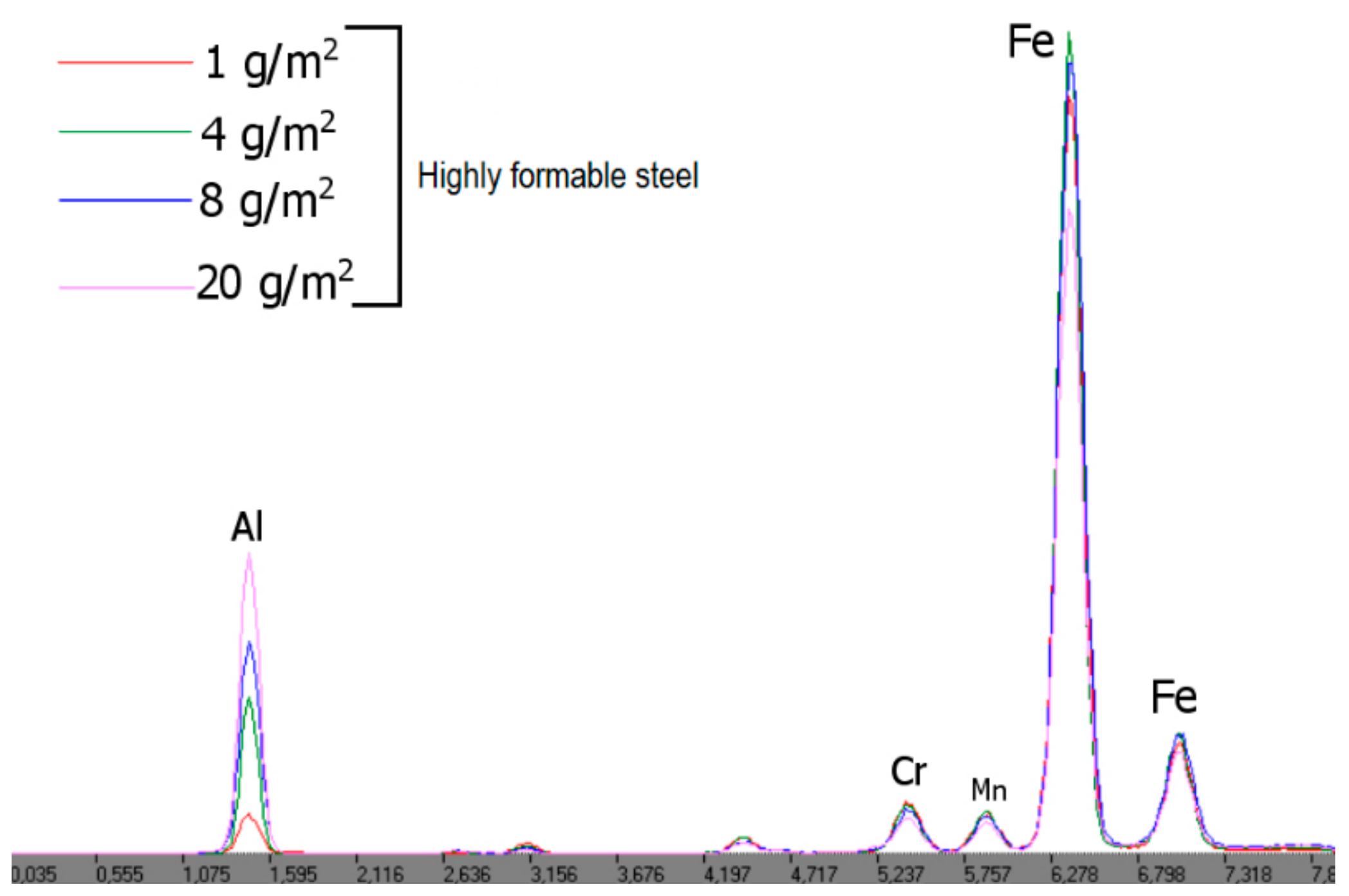
The XRF system can be calibrated by plotting the XRF intensity of either the Al line emitted by the coating or the Fe line emitted by the substrate versus the Al thickness of the coating as described previously [
14,
15]. However, due to differences in the steel grades used as substrates, the XRF intensity of the Fe line can vary with the grade of steel even in case the aluminium coating thickness, and conditions are the same (
Figure 2).
On the other hand, the XRF intensity of the Al line is independent of the steel grade (
Figure 2).
Thus, the XRF intensity of the Al line was used to determine the thickness of the Al coating as it could be used for different types of steel substrates.
Figure 3 confirms that the XRF intensity of the Al line increases proportionally with coating thickness, in the range of the studied thicknesses, meaning that it can be used as the calibration parameter.
In the calibration graph (
Figure 4), the intensity of the Al Kα Spb line is shown for aluminium coatings with thicknesses ranging from 1 to 20 g/m
2. An exponential calibration curve was derived by least-squares fitting. The correlation coefficient (R
2 value) was close to 1, which confirms that this exponential equation sufficiently describes the relationship between the XRF intensity of the Al line and the coating thickness. An algorithm for processing the XRF spectra and calculating the thickness, based on the intensity of the Al line, was established in the software.
4. Factory Acceptance Testing at the Manufacturer’s Site (FAT)
During factory tests, the standard deviation (STDEV) and root mean square deviation (RMSD) of the results obtained, using the CTA, were evaluated. In a factory acceptance test (FAT), more than ten new control samples of steel with aluminium coatings of known thicknesses were tested using the CTA analyzer pre-calibrated in the XRF laboratory in presence of the end-user. The values measured by the CTA were compared with the actual control values provided by the end user. Each sample was measured in at least five points over the entire surface (
m = 5).
Table 1 shows the results of the repeatability test including the STDEV for three control samples (
n = 3).
Table 2 shows the RMSD calculated for the entire set of control samples (
n = 8), which represents the measurement accuracy by cross-validation. Most of the values measured at the time of the FAT had a relative error of less than 5%, which meets the requirements of the end user.
Figure 5 shows a comparison of the measurement results obtained using CTA in the cross-check experiment plotted against the reference thicknesses for the control samples measured in the end user’s laboratory. Almost all of the measured results were within the maximum acceptable measurement error of 5%.
5. Conclusions
Here, we demonstrated a novel CTA system for continuous and automated analysis of the thickness of aluminium coatings, formed by PVD on moving steel strips directly during the deposition process. The performance of the system was demonstrated in FAT and long-run tests at the manufacturer site. The capabilities of the XRF method for real-time analysis of the thickness of aluminium coatings on steel directly in the process line were demonstrated for the first time. This capability was enabled by a, especially developed measuring head that is integrated into a high-temperature vacuum chamber under strict space limitations. The CTA exhibited stable performance and provided plant engineers with reliable real-time results for the entire duration of the test. The measurement accuracy shown during factory acceptance tests was less than 5%, and the measurement time was 15 s.
Based on these findings, the XRF CTA can satisfy the need for real-time thickness measurements of aluminium coatings on steel rolls during manufacturing. This information is vital to specialists who are involved in corrosion resistance and wear resistance of finished steel products, car makers who solve passivation coating problems, and aerospace industry specialists, who require metals with corrosion resistance and lubricity, at high temperatures and in vacuum conditions.


