Article

Phase Evolution and Microstructure Analysis of CoCrFeNiMo High-Entropy Alloy for Electro-Spark-Deposited Coatings for Geothermal Environment

1
Department of Industrial Engineering, Mechanical Engineering and Computer Science, University of Iceland, Hjardarhagi 2-6, 107 Reykjavík, Iceland
2
University Politehnica Bucharest, Splaiul Independentei 313, Bucharest 060042, Romania
3
Science Institute, University of Iceland, Dunhaga 3, 107 Reykjavik, Iceland
*
Author to whom correspondence should be addressed.
Coatings 2019, 9(6), 406; https://doi.org/10.3390/coatings9060406
Submission received: 20 May 2019 / Revised: 14 June 2019 / Accepted: 18 June 2019 / Published: 21 June 2019
(This article belongs to the Special Issue Coatings for Harsh Environments)

Abstract

:
In this work, a CoCrFeNiMo high-entropy alloy (HEA) material was prepared by the vacuum arc melting (VAM) method and used for electro-spark deposition (ESD). The purpose of this study was to investigate the phase evolution and microstructure of the CoCrFeNiMo HEA as as-cast and electro-spark-deposited (ESD) coating to assess its suitability for corrosvie environments encountered in geothermal energy production. The composition, morphology, and structure of the bulk material and the coating were analyzed using scanning electron microscopy (SEM) coupled with energy-dispersive spectroscopy (EDS), and X-ray diffraction (XRD). The hardness of the bulk material was measured to access the mechanical properties when preselecting the composition to be pursued for the ESD coating technique. For the same purpose, electrochemical corrosion tests were performed in a 3.5 wt.% NaCl solution on the bulk material. The results showed the VAM CoCrFeNiMo HEA material had high hardness (593 HV) and low corrosion rates (0.0072 mm/year), which is promising for the high wear and corrosion resistance needed in the harsh geothermal environment. The results from the phase evolution, chemical composition, and microstructural analysis showed an adherent and dense coating with the ESD technique, but with some variance in the distribution of elements in the coating. The crystal structure of the as-cast electrode CoCrFeNiMo material was identified as face centered cubic with XRD, but additional BCC and potentially σ phase was formed for the CoCrFeNiMo coating.

1. Introduction

The concept of complex compositionally alloys, also referred to as high-entropy alloys, has been recently proposed waiving the idea of solute and solvent and adopting the concept of a mixture of multi-principal elements in an equimolar or nearly equimolar ratio. Conceptually, this is a radical departure from the conventional notions that opens up a vast alloy design space yet to be fully explored [1]. Due to their high mixing entropy, these alloys tend to form a simple solution-like phase [2,3,4,5] and show a variety of desired properties such as high hardness and improved oxidation and corrosion resistance [6,7,8,9,10,11].
With an extended lifetime of geothermal power plants around the world, there is an increased need to have cost-effective solutions available for the maintenance of power plant components to ensure sufficient efficiency of the plant. The main maintenance problems are due to the wear, erosion, and corrosion of plant components due to the corrosive nature and high temperatures of the geothermal steam [12]. Geothermal steam generally contains dissolved gasses, the most common being carbon dioxide (CO2) and hydrogen sulfide (H2S), which are highly corrosive. Other corrosive species are, for example, chloride (Cl) and sulfur ions ( SO 4 2 ) [12,13]. One of the most crucial power plant components of geothermal power plants is the turbine, which uses the geothermal steam to produce electricity. Geothermal turbine components can experience various corrosion problems, such as the erosion corrosion of turbine blade materials and wear of rotor materials [14].
The cost of maintenance for a turbine can be lowered if the repair could be performed by a simple and viable technique with a decreased frequency [15]. Coatings of new corrosion-resistant complex materials could be performed by electro-spark deposition (ESD) to enhance the corrosion resistance of the turbine used in the geothermal environment. ESD technology is simple and effective for the deposition of metallic materials on relatively small repair areas. Usually, the ESD coating process is performed on installations equipped with a manual electrode holder, and the electrode itself has the shape of a rod. The advantages of this method include the high adhesion of the resulting coatings, the possibility of local processing of large-sized parts, its relative simplicity, a low energy consumption, high environmental compatibility, and the possibility of process automation. ESD has been successfully used to produce protective coatings for nickel alloys against oxidation [16,17,18,19].
In this paper, the potential of using the new compositionally complex alloy (high-entropy alloy) CoCrFeNiMo as a protective coating on a steel substrate is studied. Previously, this alloy was tested in a geothermal environment, well known as a highly aggressive environment, and the results were extremely encouraging [20]. The bulk material in this study was produced as an electrode for the ESD device, and the coating was fabricated with the new compositionally complex alloy. The use of such alloys in highly aggressive environments could be a solution to increase the efficiency of various processes by lowering the maintenance operation frequency needed by each process due to corrosion and erosion problems. The CoCrFeNiMo alloy was designed to have good adhesion to the steel substrate, high hardness, and improved corrosion properties. In this study, we present the results obtained for corrosion in saline water and hardness testing of the bulk alloy, and the phase evolution and microstructure analysis of the bulk material and the coating fabricated by electro-spark deposition with an electrode manufactured with the CoCrFeNiMo alloy. The main purpose of this study was to investigate the phases present in the CoCrFeNiMo coating and to establish if such a coating could be suitable for protecting the steel parts interacting with harsh environments such as corrosive geothermal steam. The novelty of this paper is the complex phase-change study from the bulk material to the coating using electro-spark deposition with an in-house-built high-entropy alloy electrode.

2. Materials and Methods

2.1. Materials and Processing

Alloy ingots were prepared by vacuum arc melting the mixture of high purity metals Co, Cr, Fe, Ni, and Mo under high-purity argon gas on water cooled Cu hearth (Material Research Furnaces, Allenstown, NH, USA). The alloys were re-melted and flipped about five times to ensure the homogeneity of the ingot. The ingots were prepared in a cylindrical shape with a diameter of 23.20 mm and height of 5.28 mm, and the weight was 17.87 g.
Table 1 presents the composition of the HEA processed in the liquid state.
The as-cast sample was machined to obtain the electrode that was then used for the electro-spark deposition on a silicon steel substrate, using a Spark Depo 300 machine (DJK Europe GmbH, Prague, Czeck Republik). The coating was performed using an argon rate of 3 L/min. Electro-spark deposition (ESD) is a pulsed-arc microwelding process using short-duration, high-current electrical pulses to deposit an electrode material on a metallic substrate. A fused, metallurgically bonded coating could be applied with a low total heat input, and the bulk substrate material remains near ambient temperatures. The short duration of the electrical pulse allows an extremely rapid solidification of the deposited material and results in an exceptionally fine-grained, homogeneous coating.
The parameters used in the electro-spark deposition process are summarized in Table 2.

2.2. Microstructural Analyses

A field emission scanning electron microscope (FE-SEM) Zeiss Supra 25 (Zeiss, Cambridge, UK) was used for the microstructural analysis, and X-ray energy dispersive spectroscopy (XEDS) equipment with a Si (Li) X-ray detector and back-scattered electron (BSE) detector. INCA Energy 300 software (Oxford Instruments, Oxford, UK) was used for the chemical composition analysis. The surface of the as-cast and electro-spark-deposited (ESD) specimens were analyzed. The cross-section of the ESD specimen was mounted in thermosetting phenol formaldehyde resin (Bakelite), and grinded and polished with SiC abrasive paper (down to 1200 grit) for SEM and EDS analysis.

2.3. X-Ray Diffraction (XRD) Analysis

XRD was performed to investigate the phase change for each fabrication method. An X’pert Pro MRD system (Panalytical, Almelo, the Netherlands) was used to obtain the XRD pattern for vacuum arc re-melting (VAM) as-cast samples, with a Gobel mirror mounted on the incident side and a parallel plate collimator on the diffracted side. Measurements were performed in both symmetric θ–2θ geometry as well as in grazing incidence geometry for increased surface sensitivity. XRD analysis was also performed on the coating to examine the phases present after the coating procedure.

2.4. Electrochemical Corrosion Testing

The electrochemical corrosion tests were done at 25 °C in NaCl 3.5% solution. This test was performed to evaluate the corrosion resistance of the CoCrFeNiMo alloy in a chloride containing solution, since geothermal fluid commonly contains Cl ions, which can facilitate the corrosion process by penetrating through the oxide films formed. The corrosion resistance was determined with the linear polarization technique by measuring the potential in the open circuit during 6 h and drawing the potentiodynamic curves from −1 V (vs. OCP—open circuit potential) to +V (vs. SCE—saturated calomel electrode), with a scanning rate of 1 mV/s. Tests for corrosion resistance assessment were performed with a potentionstat/galvanostat PARSTAT 4000 (Princeton Applied Research, Tulsa, OK, USA) with a low current module VersaSTAT LC and the potentiodynamic curves acquired with the VersaStudio v2.50.3 software. An electrochemical cell with a saturated calomel electrode was used in the testing with a platinum electrode for registering and the investigated sample as the working electrode.

2.5. Hardness Measurement

The hardness of the CoCrFeNiMo high-entropy alloy was tested along the diameter of the samples in three profiles in 20 different points, and the mean value was calculated. The hardness was measured with a Shimadzu Vickers hardness device (Shimadzu, Columbia, USA), with a 0.1-kgf load.

3. Results

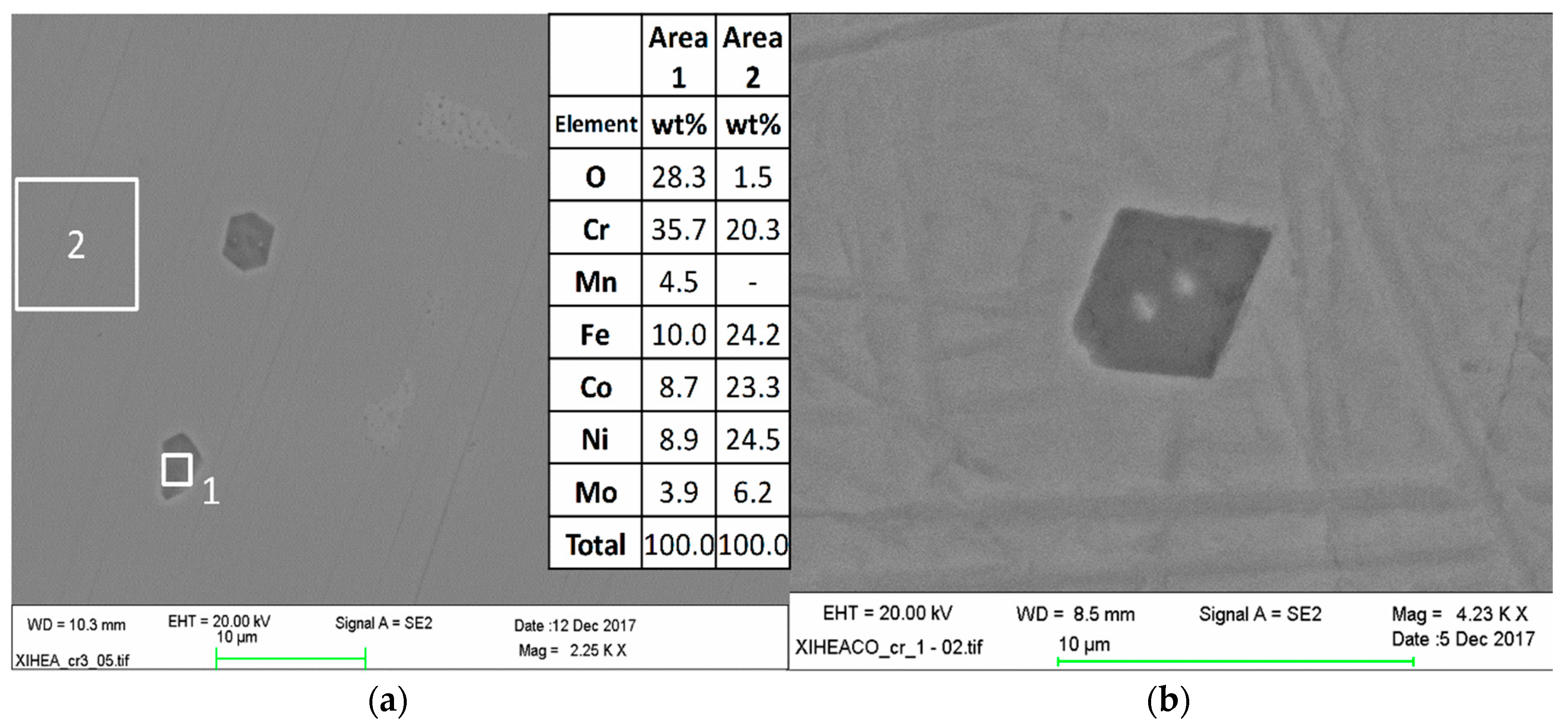
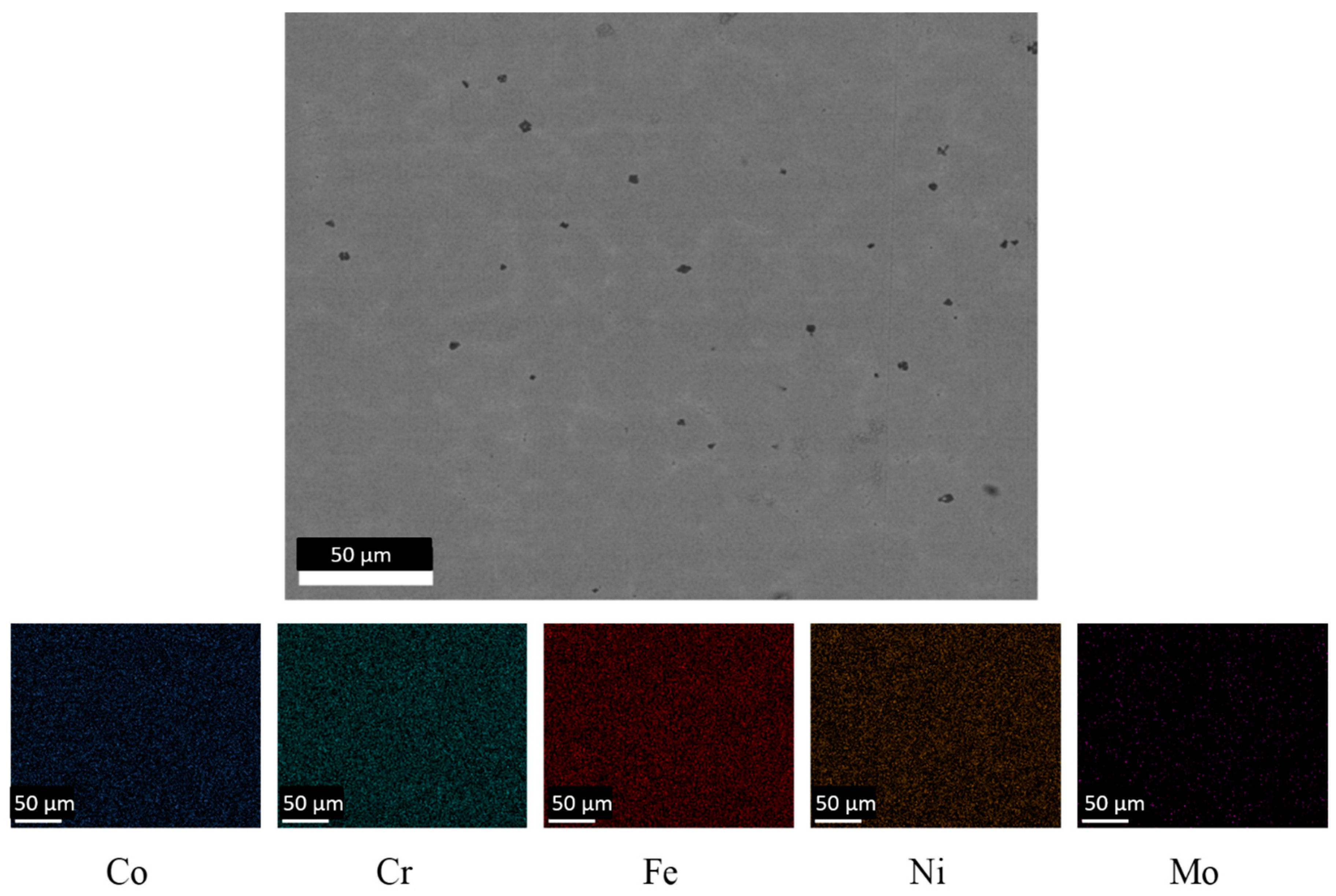
3.1. Microstructures of As-Cast CoCrFeNiMo

The microstructure of the as cast CoCrFeNiMo revealed a homogeneous structure containing one single phase and several small segregated compounds, as can be seen in Figure 1 and Figure 2. Figure 1a shows an SEM image of the microstructure of the as-cast CoCrFeNiMo alloy where the small segregated compounds are visible. The table in Figure 1 gives the elements in weight % (wt %) of the small segregated compounds detected in the EDS analysis. The area analyzed is identified with a white box in the SEM image. The compounds are rich in chromium (Cr), iron (Fe), and oxygen (O), but also contain the constitutive elements of the HEA alloy. The compounds are around 2–5 µm in width and many of them have a hexagonal shape.
Figure 2 shows a SEM image and the corresponding EDS maps for the as-cast CoCrFeNiMo bulk material. The mapping of the elements with EDS reveals the homogeneous distribution of the high-entropy alloy components.

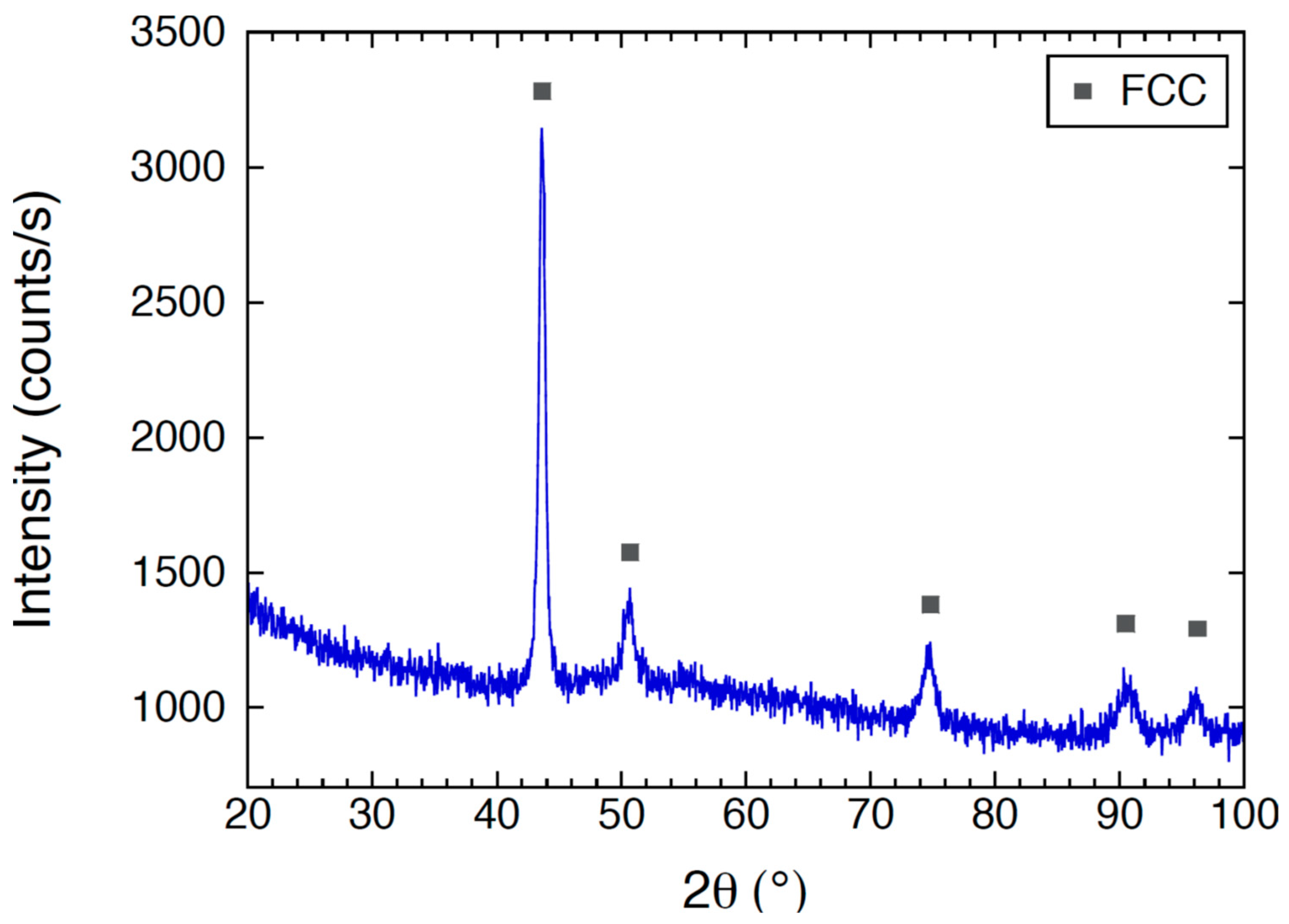
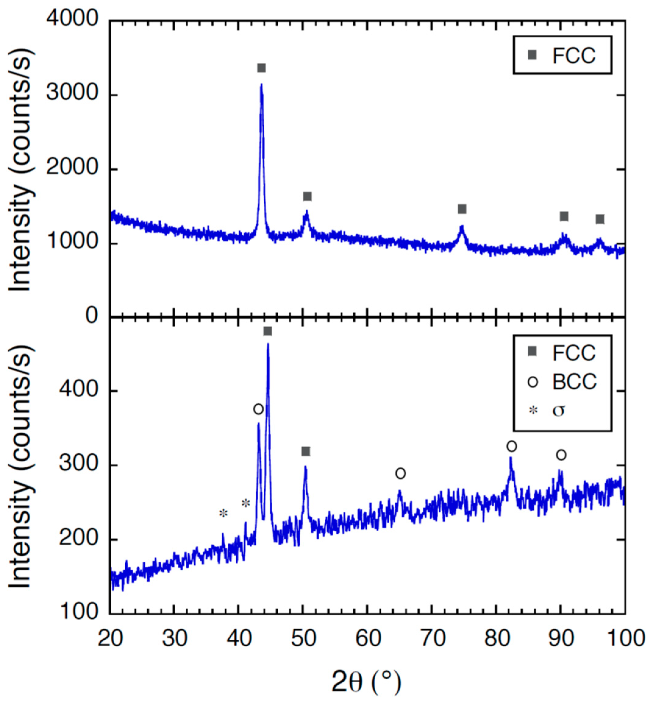
3.2. XRD Results for As-Cast CoCrFeNiMo

The XRD pattern of the as-cast CoCrFeNiMo material shows a face centered cubic (FCC) phase to be present (Figure 3).
The valence electron concentration calculated for CoCrFeNiMo was 7.8 and indicates the presence of the FCC phase [6]. This is in good agreement with the XRD analysis shown in Figure 3. The formula used for calculating the valence electron concentration was as follows [6]:
V E C = i = 1 n c i V E C i
where VECi is the valence electron concentration of each component and ci is the concentration of each component of the CoCrFeNiMo high-entropy alloy.

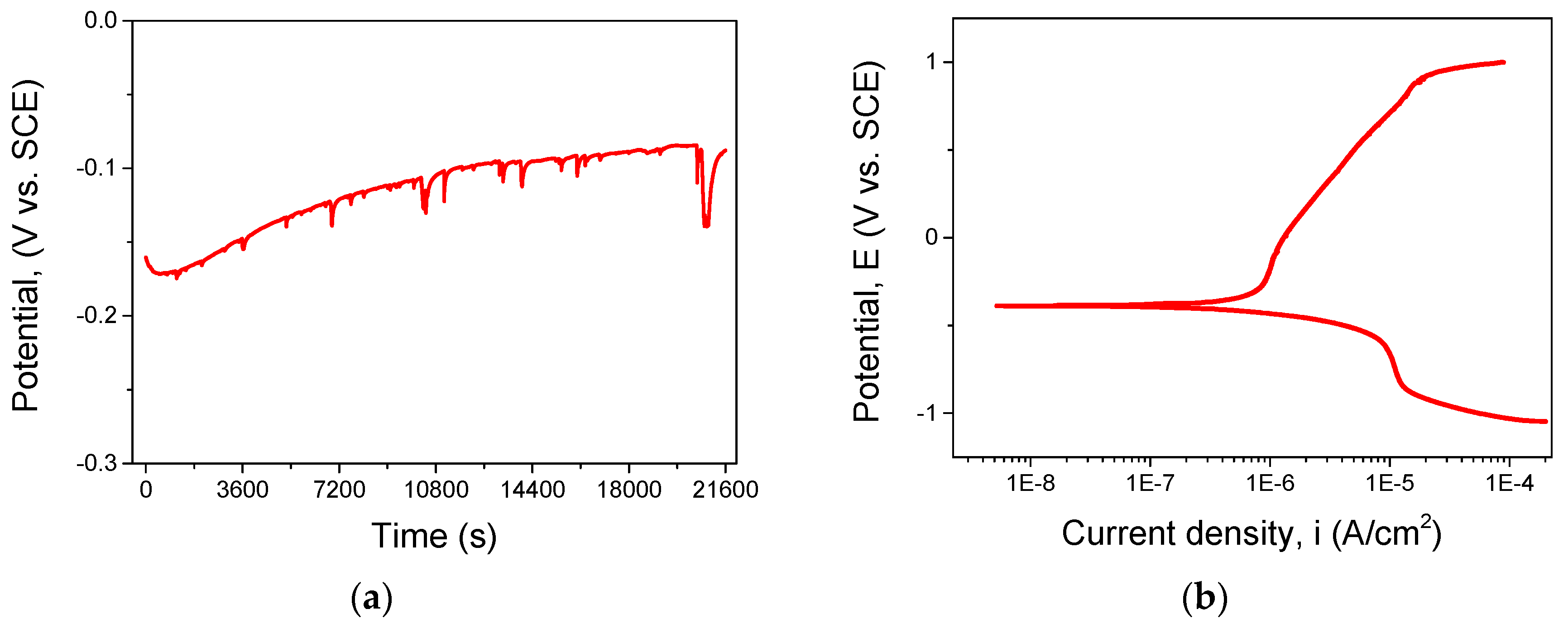
3.3. Corrosion Behavior of As-Cast CoCrFeNiMo

A standard electrochemical technique, the potentiodynamic polarization test, was used to study the corrosion behavior of the CoCrFeNiMo as-cast material. The variation of the potential in open circuit EOC and the potentiodynamic polarization curve for the as-cast CoCrFeNiMo sample are shown in Figure 4.
Table 3 presents the electrochemical parameters for the CoCrFeNiMo alloy electrochemically tested in 3.5% NaCl solution at room temperature. The following parameters have been determined to characterize the corrosion resistance of the investigated samples: open circuit potential after 6h (EOC), corrosion potential (Ecorr), corrosion current density (icorr), cathodic slope (βc), and anodic slope (βa). With the aid of the parameters determined with the Tafel extrapolation technique, the polarization resistance (Rp) was calculated.
The polarization resistance of the investigated alloy was also calculated based on the Stern-Geary equation (Equation (2)) [21,22].
R p = 2.3 β a + | β c | β a | β c | i c o r r
where βa is theanodic slope, βc thecathodic slope, and icorr the corrosion current density (µA/cm2).
The corrosion rate was calculated according to ASTM G102-89 (2004) [23] with the following equation:
C R = K i i c o r r ρ E W
where CR is the corrosion rate (mm/year), Ki is 3.27 × 10⁻³ is the material density (g/cm3), icorr the current density of material (µA/cm2), and EW the equivalent weight (g).
It can be seen from Figure 4 that the EOC shift to more electropositive values demonstrates that the alloy can develop a passive film on the surface after its deterioration. Some small deterioration of this passive film developed in the immersion in the chloride-containing solution (3.5% NaCl) can be identified by the potential drop during the immersion. The polarization curve shows an interval of passivation of the alloy until the value of −88 mV, where the breakdown potential appears. The corrosion current density value (icorr) was 0.017 µA/cm2, and the corrosion potential was around −360 mV. The corrosion rate in the NaCl 3.5% solution was calculated from to be 0.0072 mm/year, which is very low. The corrosion behavior of different HEA alloys was investigated recently by Shi et al. [24]. Their findings showed that the corrosion potential of FeCoNiCr was −460 mV after testing in the same solution (3.5% NaCl), while that of Co1.5CrFeNi1.5Ti0.5Mo0.1 was −380 mV. It was also stated that Mo-free Co1.5CrFeNi1.5Ti0.5 HEA alloy was susceptible to pitting, but the Mo added HEA alloys had a much higher passivation region.
The values obtained in the present study can also be compared with the results from testing stainless steel 630 in the same electrochemical conditions; Ecorr for 630 stainless steel in NaCl 3.5% solution was measured to be −655.6 mV and icorr 12.53 µA/cm2 [25]. This indicates that CoCrFeNiMo HEA could be a useful material for components working in saline water such as geothermal brine or even harsher environments. In a previous study, the corrosion rate for the bulk CoCrFeNiMo high-entropy alloy was measured after in-situ testing in geothermal steam at the Reykjanes power plant [20]. The value obtained was 0.00033 mm/year, which is a very low corrosion rate after exposure to geothermal steam at 200 °C and 17 bar containing H2S and CO2 gases.

3.4. Hardness Measurements of As-Cast CoCrFeNiMo

A good indicator of improvement in mechanical properties for high-entropy alloys is hardness. The hardness value for CoCrFeNiMo was determined after a series of 20 measurements along the diameter of the sample, and the mean value was calculated. The mean hardness value of the sample was 593 HV, higher than that of 304 stainless steel (201 HV) that was measured in comparison. The high hardness value obtained for the CoCrFeNiMo high-entropy alloy and the good corrosion results in 3.5% NaCl and geothermal steam encouraged us to use the bulk alloy as an electrode for a coating using the electro-spark deposition process.

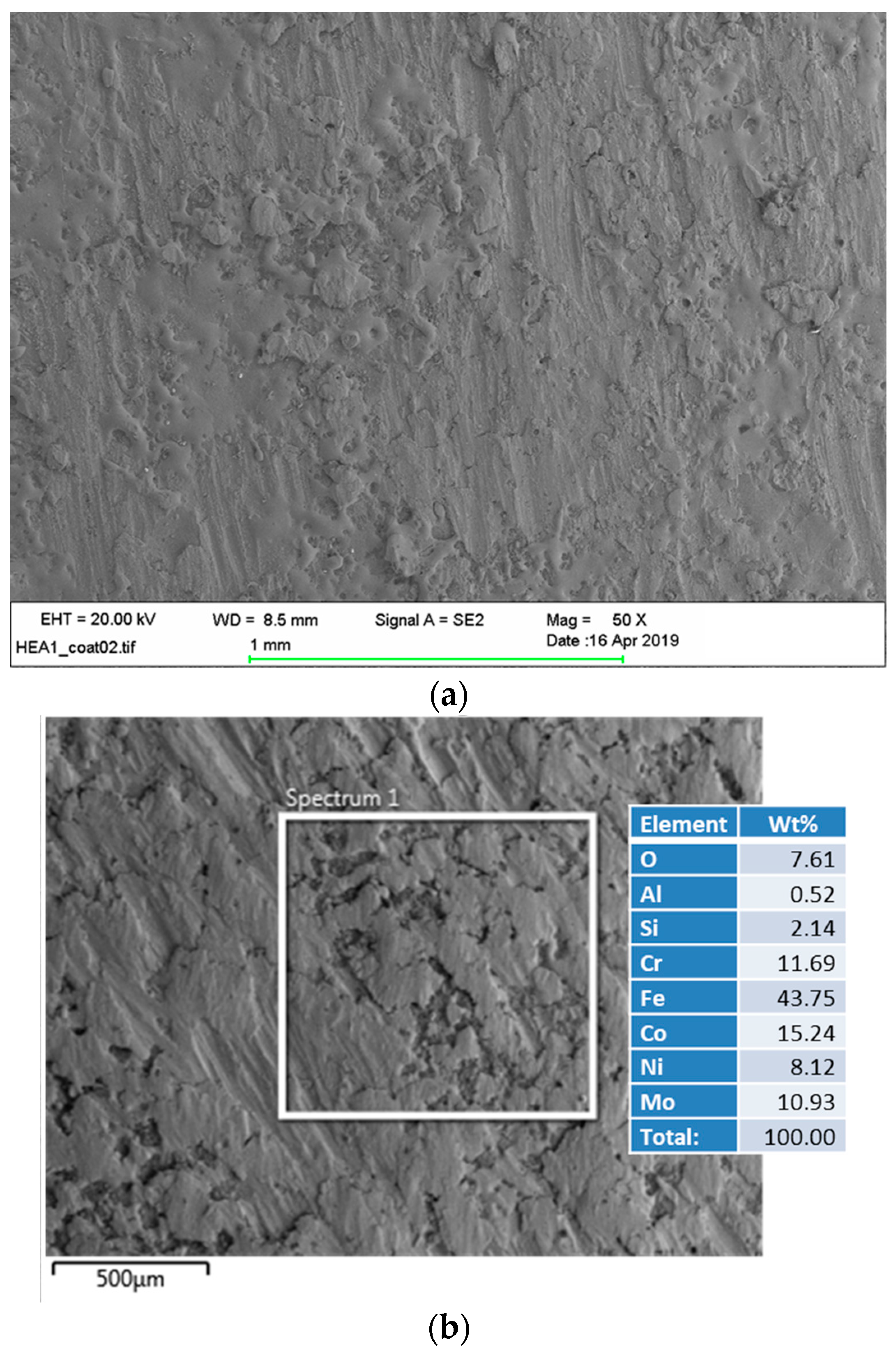
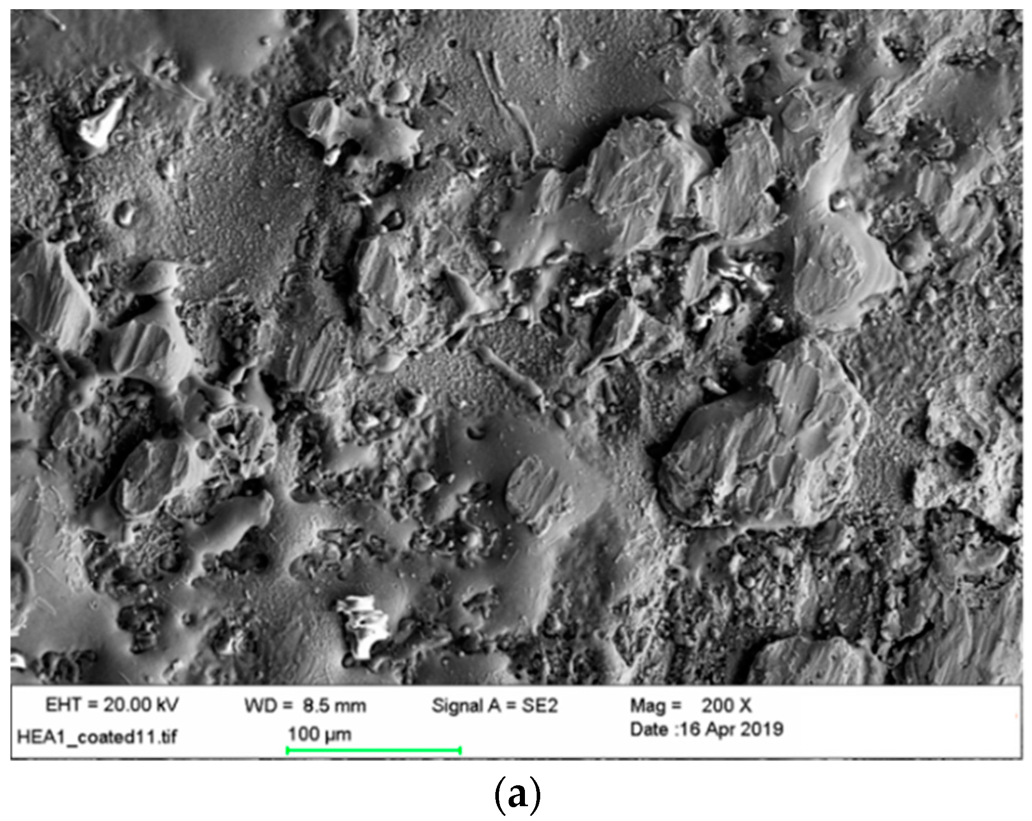
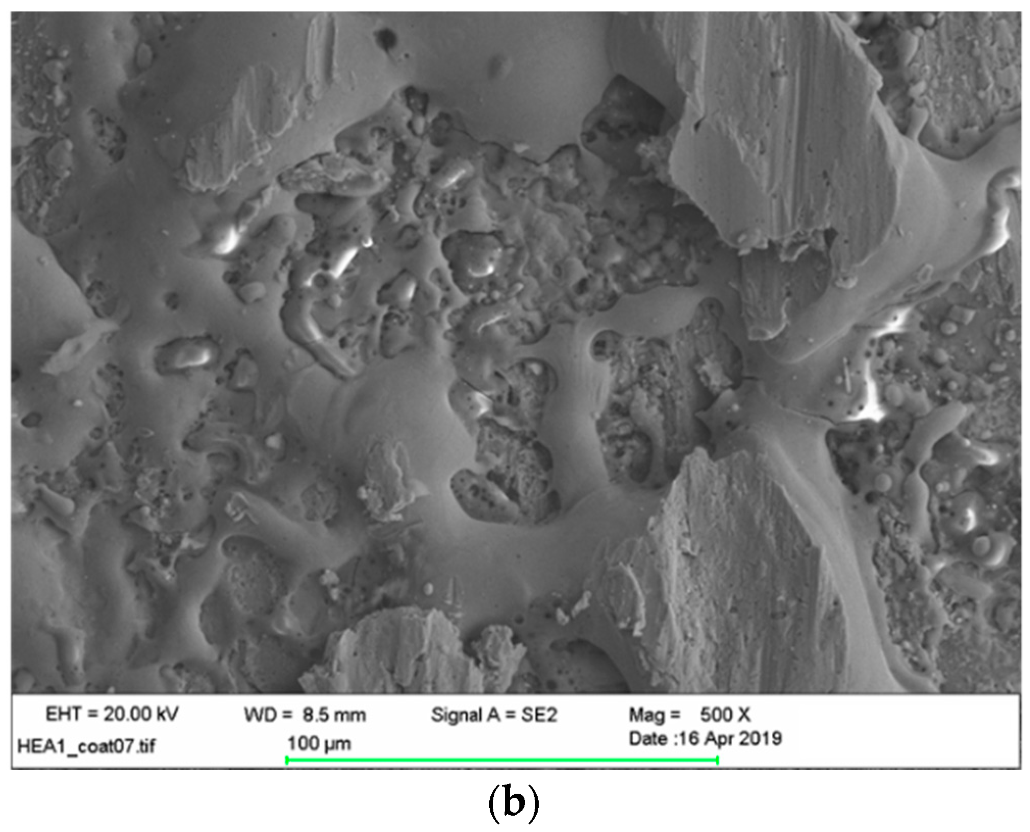
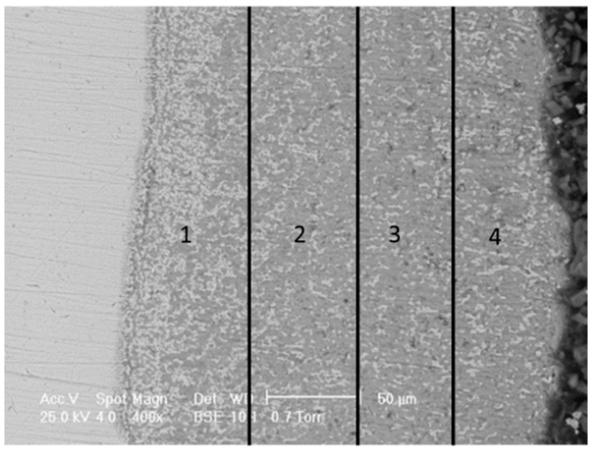
3.5. Microstructural and Chemical Composition Analysis of ESD-Prepared CoCrFeNiMo Coatings

Figure 5a,b shows a low magnification SEM image of the electro-spark-deposited CoCrFeNiMo alloy coating surface. The coating is dense and relatively homogenous. Figure 4b shows the corresponding EDS analysis of the area identified with a white box in Figure 5b. The chemical composition analysis verifies the presence of the constituent elements of the coatings, i.e., Co, Cr, Fe, Ni, and Mo, but also a minor amount of O, Al, and Si. The contrast in the SEM image indicates some variance in the distribution of elements in the coating.
Figure 6 shows SEM images of the surface of the deposited CoCrFeNiMo coating at higher magnification. At higher magnification the morphology of the coating is more apparent; large smooth islands are distributed on the surface surrounded by lower areas with more particulates.
To analyze the distribution of elements in the coating in connection with the morphology, EDS elemental maps were generated of the area shown in Figure 6. The SEM image of the area and the corresponding maps for the elements are shown in Figure 7.
It is evident from the generated maps that the elements of the HEA electrode material (Fe, Mo, Co, Ni, Cr) are present, but there is some variation in the distribution of the elements, as can be seen in the maps.
The microstructure and chemical composition of the cross-section of the deposited CoCrFeNiMo coating was also studied through SEM and EDS analysis. Figure 8 shows the BSE image of the cross-section of the coating and the EDS analysis of different parts of it. There was also compositional variation in the cross-section of the CoCrFeNiMo coatings as can be seen in Figure 8; different areas in the coating are marked 1 to 4, from the innermost part to the surface. The amount of Cr in the coating increases with the distance from the substrate; the light gray phase in the coating is rich in Fe, while the darker phase is more abundant in Cr. The oxygen content increases during the ESD process. In the first area, area 1, the iron content increases because area 1 is the most influenced by the substrate, the bonding between the layer, and the substrate being realized in that particular area. As the layer thickness increases, the substrate influence decreases as well. The increase in oxygen amount is due to the coating process. The ESD process sometimes promotes oxide formation due to the air atmosphere. The coating is realized layer by layer and sometimes part of the chromium segregates and forms an oxide layer during the process, which in the end can have a protective role for the coating itself [24].

3.6. XRD Analysis of CoCrFeNiMo Coating

Figure 9 shows the XRD pattern of the CoCrFeNiMo ESD coating and, for comparison, the pattern for the bulk material.
The XRD of the coating reveals that two main phases are present after the electro-spark deposition (ESD). The dominant phase in the bulk material is FCC, as predicted by the VEC calculation presented in Section 3.2. The formation of the FCC phase is promoted when most of the binary constituents crystallize in the FCC structure, as CoNi, CoFe, and FeNi. The complete solubility of CoNi and sufficient solubility of FeNi could stabilize the FCC phase in the bulk material [26,27,28,29,30]. The BCC phase after the ESD process could be due to the presence of Mo in this high-entropy alloy. Additionally, the small peaks around 40° in the XRD pattern could potentially be due to the formation of a sigma phase that can form in CoCrFeNiMo HEA materials when Mo is added to the mix [1,31]. These aspects are further discussed in Section 4.

4. Discussion

A unique feature of high-entropy alloys is the ability of different crystal structure elements to combine and form a single phase. The CoCrFeNiMo high-entropy alloy consists of elements of similar sizes (Co, Cr, Fe, Ni,) and the same valences and electronegativity. Mo is different in size but close to the other elements in terms of valence and electronegativity. Co is hexagonal close packed at room temperature but transforms to FCC when the temperature increases (after 450 °C it becomes FCC). The phase transformation in HEA could be governed to a higher extent by the binary constituents’ pairs that evolve first, rather than by the individual elements themselves. The bulk material CoCrFeNiMo contains pairs of CoNi, NiCr, NiFe, and NiMo with an FCC structure [32]. The CoFe pair presents a BCC structure, and CoCr, CoMo, FeCr, and FeMo tend to stabilize the σ phase. In the case of coatings, the interface is influenced by the substrate. It has been found that the sigma phase can form from the BCC phase without precipitation of the FeCr system [33]. The electro-spark deposition process ensures good bonding because the first layers are mixed with the substrate (as shown in Figure 8 zone 1). This could explain the appearance of a mixture of phases and variance in the composition in the coated layer. The addition of molybdenum tends to stabilize the formation of a BCC structure and appearance of a σ phase. The formation of the σ phase has also been reported in CoCrFeNiMox alloys with increasing Mo content [1,31]. Increasing Mo content has also been shown to transform the cast structure into a eutectic structure [34]. Despite that, the detected phase of the bulk alloy is FCC, while the XRD pattern (Figure 9b) reveals a mixture of phases for the coating. In the coating process, a high temperature is generated, which can modify the phases in the structure. The results from the XRD and the microstructural and EDS analyses presented in Figure 8, areas 1, 2, 3, and 4 confirm this. The increase in Mo content transforms the eutectic microstructure into a hypo/hyper eutectic structure. This preference is probably due to a higher driving force for the formation of a stable σ phase of the FeCrMo type. Cr is an important constituent in HEAs and, as already discussed in the context of equiatomic alloys, Cr stabilizes the BCC structure and can promote the formation of the σ phase particularly in the presence of Fe, Co, and Ni. The bulk alloy processing method, due to the rapid cooling process, stabilized the FCC phase in the CoCrFeNiMo high-entropy alloy. The binary pairs CoFe and CrMo in the high entropy alloy tend to stabilize the BCC phase. The BCC phase is present in the coating due to the mechanism of rapid cooling during the electro-spark deposition process. The coating process is based on metallurgical bond formation due to an electrical discharge, which increases the temperature for the electrode and substrate, and then the layer is cooled almost instantaneously. The rapid cooling of the high entropy alloy on the substrate favors the BCC phase formation. Cr, Fe, Mo have a BCC structure at room temperature and usually promote the BCC phase formation. The σ phase is sometimes observed in Cr-containing steels and has a typical composition of equiatomic FeCr with a tetragonal structure. The σ phase has also been observed with equiatomic CoCr or FeMo in binary CoCr and FeMo alloys. A large number of HEAs containing Fe and/or Co together with higher amounts of Cr and/or Mo have shown the formation of the σ phase at various stages in their processing. In HEAs, the σ phase is also a multicomponent solid solution. The formation of the σ phase is an indication that different types of solid solutions in HEAs could form depending on the interaction and atomic size difference between elements and not just the configurational entropy alone. The σ phase is in fact a topologically close-packed phase in which components with larger atomic size occupy one specific set of lattice sites while smaller atoms occupy another set so as to get a higher number of bonds to lower its overall free energy, although the interactions (or enthalpy of mixing) between components are low [27]. The electro-spark deposition using the heated electrode and electric current to ensure the spark deposition modified the phases in the alloy and promoted the formation of new phases for the coating. The substrate influence and the coating process induced the mixture of phases in the coating, forming FCC, BCC, and potentially the σ phase in the coated layer.
The corrosion rate of the CoCrFeNiMo HEA bulk material calculated from the electrochemical parameters obtained in the corrosion test in the salt solution at room temperature was very low (0.0072 mm/year) and thus encouraging for the further study of this alloy for the chloride-containing geothermal fluid commonly encountered in geothermal energy utilization. The corrosion resistance of the CoCrFeNiMo bulk material can be attributed to the passivation of the alloy by the formation of thin chromium-oxide-rich surface film, and also to the presence of Mo, which can decrease the susceptibility to corrosion, particularly pitting corrosion, by acting as a barrier at the surface against electrochemical attack. Mo-free containing HEA alloys have been found to pit in 1 M NaCl, while the Mo-containing alloys were not susceptible to pitting [25]. Whether the formation of additional phases, such as the BCC phase, in the fabricated CoCrFeNiMo HEA coating in this study has a large effect on the corrosion resistance of the coatings compared to the bulk material is being studied in our ongoing project dedicated to developing HEA coatings for geothermal environments. It has been reported that both BCC and FCC phases can be formed in HEA coatings; Ye at al. [35] prepared AlxCoCrCuFeNi HEA coatings with laser cladding on AISI 1045 steel, which were proven to have both FCC and BCC structures. A relatively homogenous distribution of elements was observed, and the coatings possessed better corrosion resistance than the 314L stainless steel tested in the same conditions (0.05 mol/L HCl) [36]. This encourages us to continue the research using 1 M NaCl solutions at room temperature, and in simulated and in-situ in geothermal environments at elevated temperatures.
The hardness was measured to assess the mechanical properties of the CoCrFeNiMo HEA in this study, and the results were promising. The value obtained, greater than that of stainless steel, could positively influence the mechanical properties of the coating and wear resistance. In our further study, this will be investigated, as well as the potential evaluation of the fracture toughness at micro-scale with the experimental approach reported in the literature [35].

5. Conclusions

  • Vacuum-arc-melted CoCrFeNiMo HEA was fabricated and used for producing an electro-spark-deposited coating.
  • Testing of the as-cast material revealed high hardness (593 HV) and low corrosion rates (0.0072 mm/year), which is promising for the high wear and corrosion resistance needed for the harsh geothermal environment.
  • Adherent and dense coating was obtained, but some variance in the distribution of elements was observed in the coating, with Cr increasing with the distance from the substrate.
  • The crystal structure of the as-cast electrode CoCrFeNiMo material was identified as FCC with XRD, but additional phases were formed in the CoCrFeNiMo coating, such as BCC and potentially the σ phase.

Author Contributions

S.N.K., conceptualization, analysis of data, methodology, writing of manuscript; I.C., conceptualization, analysis of data, methodology, writing of manuscript; L.E.G., contributed with resources, fabrication, and methodology; A.I.T., performed SEM and EDS analysis and analyzed the data, contributed to XRD analysis, reviewing of paper; R.S., fabrication of bulk material; C.C., performed the corrosion tests and analysis; F.M., performed analysis of data and XRD tests.

Funding

This work is part of the H2020 EU project Geo-Coat: Development of novel and cost-effective corrosion resistant coatings for high temperature geothermal applications. Call H2020-LCE-2017-RES-RIA-TwoStage (Project No. 764086).

Acknowledgments

The authors would like to acknowledge the resources and collaborative efforts provided by the consortium of the Geo-Coat project No. 764086. The authors want to thank Florin Miculescu for his help in analyzing the microstructure of the cross-sectioned samples of the coated layer with SEM and EDS analyses.

Conflicts of Interest

The authors declare no conflict of interest.

References

  1. Liu, W.H.; Lu, Z.P.; He, J.Y.; Luan, J.H.; Wang, Z.J.; Liu, B.; Liu, Y.; Chen, M.W.; Liu, C.T. Ductile CoCrFeNiMox high entropy alloys strengthened by hard intermetallic phases. Acta Mater. 2016, 116, 332–342. [Google Scholar] [CrossRef]
  2. Zou, Y.; Ma, H.; Spolenak, R. Ultra strong ductile and stable high-entropy alloys at small scales. Nat. Commun. 2015, 6, 7748. [Google Scholar] [CrossRef] [PubMed]
  3. Zhang, Y.; Stocks, G.M.; Jin, K.; Lu, C.; Bei, H.; Sales, B.C.; Wang, L.; Beland, L.K.; Stoller, R.E.; Samolyuk, G.D.; et al. Influence of chemical disorder on energy dissipation and defect evolution in concentrated solid solution alloys. Nat. Commun. 2015, 6, 8736. [Google Scholar] [CrossRef] [PubMed]
  4. Tsai, M.H. Three strategies for the design of advanced high-entropy alloys. Entropy 2016, 18, 252. [Google Scholar] [CrossRef]
  5. Zhang, Y.; Zhou, Y.J.; Lin, J.P.; Chen, G.L.; Liaw, P.K. Solid-solution phase formation rules for multi-component alloys. Adv. Eng. Mater. 2008, 10, 534–538. [Google Scholar] [CrossRef]
  6. Guo, S.; Liu, C.T. Phase stability in high entropy alloys: formation of solid solution phase or amorphous phase. Prog. Nat. Sci. Mater. Int. 2011, 21, 433–446. [Google Scholar] [CrossRef]
  7. Yang, X.; Zhang, Y. Prediction of high-entropy stabilized solid-solution in multi-component alloys. Mater. Chem. Phys. 2012, 132, 233–238. [Google Scholar] [CrossRef]
  8. Guo, S.; Hu, Q.; Ng, C.; Liu, C.T. More than entropy in high-entropy alloys: Forming solid solutions or amorphous phase. Intermet. 2013, 41, 96–103. [Google Scholar] [CrossRef]
  9. Ren, M.X.; Li, B.S.; Fu, H.Z. Formation condition of solid solution type high entropy alloy. Trans. Nonferrous Metall. Soc. China 2013, 23, 991–995. [Google Scholar] [CrossRef]
  10. Liu, W.H.; Wu, Y.; He, J.Y.; Zhang, Y.; Liu, C.T.; Lu, Z.P. The phase competition and stability of high-entropy alloys. JOM 2014, 66, 1973–1983. [Google Scholar] [CrossRef]
  11. Wang, Z.; Guo, S.; Liu, C.T. Phase selection in high-entropy alloys: From nonequilibrium to equilibrium. JOM 2014, 66, 1966–1972. [Google Scholar] [CrossRef]
  12. Karlsdottir, S.N. Corrosion, scaling and material selection in geothermal energy production. In Comprehensive Renewable Energy, 1st ed.; Sayigh, A., Ed.; Elsevier: Amsterdam, The Netherlands, 2012; pp. 239–256. [Google Scholar]
  13. Karlsdottir, S.N.; Hjaltason, S.M.; Ragnarsdottir, K.R. Corrosion behaviour of materials in hydrogen sulphide abatement system at Hellisheiði geothermal power plant. Geothermics 2017, 70, 222–229. [Google Scholar] [CrossRef]
  14. Matsuda, H. Maintenance for reliable geothermal turbine. GRC Trans. 2006, 30, 755–760. [Google Scholar]
  15. Brown, A.; Müller, S.; Dobrotková, Z. Renewable Energy: Markets and Prospects by Technology; IEA: Paris, France, 2011; 66p. [Google Scholar]
  16. Kudryashov, A.E.; Potanin, A.Y.; Lebedev, D.N.; Sukhorukova, I.V.; Shtansky, D.V.; Levashov, E.A. Structure and properties of Cr-Al-Si-B coatings produced by pulsed electrospark deposition on a nickel alloy. Surf. Coat. Technol. 2016, 285, 278–288. [Google Scholar] [CrossRef]
  17. Xie, Y.J.; Wang, M.C. Isothermal oxidation behaviour of electrospark deposited MCrAlX-type coatings on a Ni-based superalloy. J. Alloys Compd. 2009, 480, 454–461. [Google Scholar] [CrossRef]
  18. Xie, Y.J.; Wang, M.C. Epitaxial MCrAlY coating on a Ni-base superalloy produced by electrospark deposition. Surf. Coat. Technol. 2006, 201, 3564–3570. [Google Scholar] [CrossRef]
  19. Podchernyaeva, I.A.; Panasyuk, A.D.; Teplenko, M.A.; Podol’skii, V.I. Protective coatings on heat-resistant nickel alloys (Review). Powder Metall. Met. Ceram. 2000, 39, 434–444. [Google Scholar] [CrossRef]
  20. Csáki, I.; Stefanoiu, R.; Karlsdottir, S.N.; Geambazu, L.E. Corrosion behavior in geothermal steam of CoCrFeNiMo high entropy alloy. In Proceedings of the CORROSION 2018, Phoenix, AZ, USA, 15–19 April 2018. [Google Scholar]
  21. Stern, M. A method for determining corrosion rates from linear polarization data. Corrosion 1958, 14, 60–64. [Google Scholar] [CrossRef]
  22. Sheir, L.L.; Jarman, R.A.; Burstein, G.T. Corrosion: Corrosion Control; Butterworth-Heinemann: Boston, MA, USA, 1994; pp. 19–38. [Google Scholar]
  23. ASTM G4-01(2014): Standard Guide for Conducting Corrosion Tests in Field Applications; ASTM International: West Conshohocken, PA, USA, 2008.
  24. Shi, Y.; Yang, B.; Liaw, P.K. Corrosion-resistant high entropy alloys: A review. Metals 2017, 7, 43. [Google Scholar] [CrossRef]
  25. Sohi, M.H.; Ebrahimi, M.; Raouf, A.H.; Mahboubi, F. Comparative study of the corrosion behavior of plasma nitrocarburised AISI 4140 steel before and after post-oxidation. Mater. Des. 2010, 31, 4432–4437. [Google Scholar] [CrossRef]
  26. Praveen, S.; Murty, B.S.; Kottada, R.S. Alloying behaviour in multi-component AlCoCrCuFe and NiCoCrCuFe high entropy alloys. Mater. Sci. Eng. 2012, 534, 8389. [Google Scholar] [CrossRef]
  27. Liu, W.H.; Wu, Y.; He, J.Y.; Nieh, T.G.; Lu, Z.P. Grain growth and the Hall-Petch relationship in a high-entropy FeCrNiCoMn alloy. Scr. Mater. 2013, 68, 526–529. [Google Scholar] [CrossRef]
  28. Otto, F.; Dlouhý, A.; Somsen, C.; Bei, H.; Eggeler, G.; George, E.P. The influences of temperature and microstructure on the tensile properties of a CoCrFeMnNi high-entropy alloy. Acta Mater. 2013, 61, 5743–5755. [Google Scholar] [CrossRef] [Green Version]
  29. Zhu, C.; Lu, Z.P.; Nieh, T.G. Incipient plasticity and dislocation nucleation of FeCoCrNiMn high-entropy alloy. Acta Mater. 2013, 61, 2993–3001. [Google Scholar] [CrossRef]
  30. Tsai, K.Y.; Tsai, M.H.; Yeh, J.W. Sluggish diffusion in Co-Cr-Fe-Mn-Ni high entropy alloys. Acta Mater. 2013, 61, 4887–4897. [Google Scholar] [CrossRef]
  31. Shun, T.T.; Chang, L.Y.; Shiu, M.H. Microstructure and mechanical properties of multiprincipal component CoCrFeNiMox alloys. Mater. Charact. 2012, 70, 63–67. [Google Scholar] [CrossRef]
  32. Hansen, M. Constitution of Binary Alloys, Metallurgy and Metalurgical Enginerring Series; McGraw-Hill: New York, NY, USA, 1958; pp. 966–982. [Google Scholar]
  33. Tsai, M.-H.; Tsai, K.-Y.; Tsai, C.-W.; Lee, C.; Juan, C.-C.; Yeh, J.-W. Criterion for Sigma phase formation in Cr- and V-containing high-entropy alloys. Mater. Res. Lett. 2013, 1, 207–212. [Google Scholar] [CrossRef]
  34. Zhu, J.M.; Fu, H.M.; Zhang, H.F.; Wang, A.M.; Li, H.; Hu, Z.Q. Microstructures and compressive properties of multicomponent AlCoCrFeNiMox alloys. Mater. Sci. Eng. 2010, 527, 6975–6979. [Google Scholar] [CrossRef]
  35. Ye, X.; Ma, M.; Cao, Y.; Liu, W.; Gu., Y. The property research on high-entropy alloy AlxFeCoNiCuCr coating by laser cladding. Phys. Procedia 2011, 12, 303–312. [Google Scholar] [CrossRef]
  36. Ast, J.; Ghidelli, M.; Durst, K.; Göken, M.; Sebastiani, M.; Korsunsky, A.M. A review of experimental approaches to fracture toughness evaluation at the micro-scale. Mater. Des. 2019, 173, 107762. [Google Scholar] [CrossRef]
Figure 1. (a) Scanning electron microscopy (SEM) image showing the microstructure of the as-cast CoCrFeNiMo material revealing segregated compounds within the bulk and a table with energy-dispersive spectroscopy (EDS) analyses of areas highlighted with white boxes in image (a); and (b) SEM image of the compound at higher magnification.
Coatings 09 00406 g001
Figure 2. Scanning electron microscopy (SEM) image and EDS maps of the as-cast CoCrFeNiMo bulk material.
Coatings 09 00406 g002
Figure 3. The X-ray diffraction (XRD) pattern for the as-cast CoCrFeNiMo material.
Coatings 09 00406 g003
Figure 4. (a) Open circuit potential variation and (b) potentiodynamic polarization curve for the bulk CoCrFeNiMo alloy tested electrochemically in 3.5% NaCl solution.
Coatings 09 00406 g004
Figure 5. (a,b) SEM images of the surface of the CoCrFeNiMo coating; (b) includes a table with results from EDS analysis of the area identified with a white box in the SEM image.
Coatings 09 00406 g005
Figure 6. Surface view of the deposited CoCrFeNiMo coating; SEM images at (a) lower magnification and (b) higher magnification.
Coatings 09 00406 g006aCoatings 09 00406 g006b
Figure 7. EDS elemental maps generated of the area shown in Figure 6.
Coatings 09 00406 g007
Figure 8. Back scattered electron (BSE) image of the cross-section of the CoCrFeNiMo coating and results from EDS analysis of the areas labelled in the BSE image.
Coatings 09 00406 g008

ElementsCoCrFeNiMoSiCaTiO
Substrate-16.566.410.43.90.80.91.0-
Area 13.217.744.710.94.3---19.9
Area 21.618.637.09.84.9---28.1
Area 31.618.834.210.65.0---29.7
Area 42.418.529.411.76.8---31.2
Figure 9. XRD pattern for CoCrFeNiMo ESD coating (bottom graph) and as-cast material (top graph) for comparison.
Coatings 09 00406 g009
Table 1. Nominal composition for CoCrFeNiMo.
Elements (at%)CoCrFeNiMo
CoCrFeNiMo2020202020
Table 2. Parameters used for CoCrFeNiMo electrospark deposition.
SampleCapacitance (µF)Voltage (V)Frequency (Hz)Atmosphere
CoCrFeNiMo201003.5Argon
Table 3. Electrochemical parameters of CoCrFeNiMo alloy in the chloride-containing solution (3.5% NaCl) at room temperature.
SampleEoc (mV)Ecorr (mV)icorr (µA/cm2)βc (mV)βa (mV)Rp (kΩ × cm2)CR (mm/year)
VAR_HEA−88−3600.017207.1392.961748.610.0072

