Abstract
TiAlN has been widely used in cutting tool coating due to its excellent mechanical and thermal performances. However, the research on the TiAlN coating effect on cutting temperature is not comprehensive enough. In this paper, the friction tests at elevated temperature and hard machining H13 hardened steel tests are conducted by using TiAlN coated tools and uncoated tools, respectively. The results of using TiAlN coated tools are compared with those from using uncoated tools. It is found that the coefficient of friction (COF) between TiAlN coated tool and H13 hardened steel is reduced to 0.63 at 800 °C. The COF value is 0.75 for uncoated tool. Under the same cutting conditions, the TiAlN coating shortens tool-chip contact length. The tangential cutting forces and cutting zone temperatures are decreased with smaller COF and shorter tool-chip contact length. Due to the lower thermal conductivities of TiAlN coating and the Al2O3 oxide layer formatted at tool rake face, the cutting heat conducted into cutting tool substrate was reduced. The cutting temperatures in TiAlN coated tool substrate are decreased by at least 10.68% in this study. The TiAlN coating reduces the cutting temperature by decreasing the cutting heat generation and conduction.
1. Introduction
TiAlN coated tools have become a recent hotbed of discussion within the metal cutting field. Both economical and environmental factors drive manufacturers to search for ways to avoid environmental pollution and high production costs. Thus, the application of hard coatings became popular in factories, especially TiAlN coating. Due to their excellent properties, TiAlN coated tools are often utilized in metal cutting processes under dry cutting conditions [1,2,3,4]. The use of TiAlN coated cutting tools improves productivity and extends cutting tool life, compared with traditional cemented carbide tools in metal cutting process [5,6]. However, the high cutting temperature is still the main restraining factor for the application of TiAlN coated tools in the metal cutting process [7].
Metal cutting studies in terms of thermal aspects have focused on determining the cutting heat generation and cutting heat conduction. During the metal cutting process, cutting heat is mainly generated in three regions, as shown in Figure 1. The cutting temperature of the cutting tool is mainly influenced by the heat generated in primary deformation and secondary deformation zones [8]. The coefficient of friction (COF) between the tool rake face and chip impacts the heat produced in the secondary deformation zone [9,10]. Tool-chip contact conditions and cutting tool thermal-physical properties affect the heat conduction from the chip into the cutting tool [11,12,13,14,15].
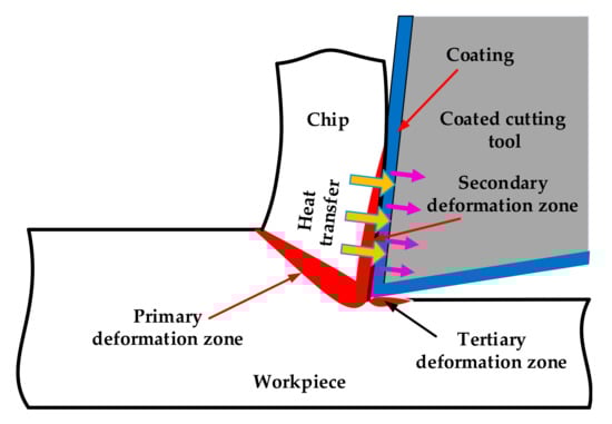
Figure 1.
Heat generation and heat conduction during the cutting process.
Several investigations have suggested that the lower cutting temperature of TiAlN coated tool during the metal cutting process was because of the coating’s ability to reduce the friction between the tool rake face and the chip. The tribology of metal cutting is characterized by severe conditions of the tool-chip contact interface. High cutting temperatures and high stresses as well as freshly generated surfaces define a unique tribosystem [16]. At present, too many researchers have studied the friction between the tool and the chip [12,17]. Rech [12] investigated the influence of different cutting tool coatings on tribological phenomena in dry orthogonal turning. The coefficient of friction between the tool rake face and the chip was determined by the ratio of the feed force and cutting force. The dry orthogonal machining was conducted on 27MnCr5 steel and three kinds of coated tools (TiN, TiAlN and TiAlN + MoS2) were compared with an uncoated tool. It was found that TiAlN coating could reduce the COF at the 200 m/min cutting speed. Grzesik [17] calculated the COF using the same method. The TiAlN coated tool provided the lowest value of the COF among the three coated tools (TiC/Al2O3/TiN, TiC/TiCN/Al2O3/TiN and TiAlN) when AISI 1045 medium carbon steel was machined. However, when machining AISI 304 stainless steel, the value of the COF between the TiAlN coated tool rake face and chip was the biggest. Considering the complexity of tool-chip contact condition, many researchers have studied the COF between TiAlN coated tool and workpiece material by using some tribometer systems [10,18,19,20,21]. Mo [18,19], Liu [20] and Jiang [21] obtained the values of the COF between TiAlN coated tool and workpiece by ball-on-disk using a CETR UMT-2 tribometer. These friction tests were conducted under ambient temperature. However, the tool-chip contact area was at an elevated temperature during the metal cutting process. Ozlu et al. [10] compared the COF values of different workpiece-tool couples in cutting and non-cutting tests. They claimed that the values obtained by non-cutting tests at ambient temperature were always smaller than the values obtained by cutting tests. Therefore, this proved that high temperature makes a great difference to the friction phenomenon of tool-chip contact interface compared to ambient temperature.
Friction between cutting tool rake face and chip determines the cutting heat generation in secondary deformation zone. The tool-chip contact length influences the friction of tool-chip contact interface. Notable investigations on the tool-chip contact length in metal machining have been performed over the last five decades such as those by Friedman [22], Balaji [13,23], Mativenga and Sheikh [15,24,25,26,27] and Grzesik [14]. Mativenga et al. [25] pointed out that cutting tool and workpiece material, cutting parameters and cutting operation type affected tool-chip contact length. And tool-chip contact length influenced many factors, such as cutting forces, cutting tool temperature, power consumption, and so on. Akbar [27] investigated the tool-chip contact length in dry orthogonal machining with TiAlN and TiN coated tools. The cutting speeds ranged from 100 to 880 m/min. The cutting tests were conducted on AISI/SAE 4140 high-tensile alloy steel with an external diameter of 200 mm and a tube thickness of 2.5 mm. They concluded that the tool-chip contact length decreased with the increase of the cutting speed for both of the two tools. The TiAlN coated tool exhibited longer tool-chip contact length than TiN coated tool did. Grzesik [14] compared the tool-chip contact lengths of different tool-workpiece material pairs under different cutting speeds. They got the same conclusion as Akbar [27]. When AISI 304 steel was machined, coated tools presented a shorter contact length than the uncoated carbide tool. In contrast, coated tools exhibited a longer tool-chip contact length than a uncoated carbide tool when AISI 304 steel was substituted for by AISI 1045 steel.
The cutting heat conducted to the cutting tool depends on the tool-chip contact length, thermal properties of coating and workpiece material, and the thickness value of coating [28]. Akbar [27] reported that TiAlN coating induced less cutting heat conducting into the cutting tool due to its lower thermal conductivity. Balaji and Mohan [13] proposed that the value of cutting heat conduction from chip to coated tool rake face was inversely proportional to the thermal conductivity of coatings. In addition, the Al in the TiAlN coating was highly active metal ion, which was very easy to use to generate an Al2O3 oxide layer with O2 at elevated temperature [29]. Coelho et al. [30] declared that the Al2O3 oxide layer was generated at the TiAlN coated tool rake face when AISI 4340 steel was machined. It was confirmed by many researchers [31,32] that the Al2O3 oxide layer improved the thermal stability and oxidation resistance of TiAlN coating. The Al2O3 oxide layer prevents the coating from being oxidized and its thermal conductivity is lower than that of TiAlN coating [33]. The lower thermal conductivity of Al2O3 oxide layer means that it can more effectively block cutting heat conducting into cutting tool. Both TiAlN coating and Al2O3 oxide layer could obstruct cutting heat conducting into coated tools substrate. However, based on a literature review, it seems that there are few studies have considered the thermal barrier effect of TiAlN coating.
To have a better understanding of tribology and thermal performance of TiAlN coating, friction tests at elevated temperature and hard machining tests were conducted in this study. To investigate the influences of TiAlN coating on cutting heat generation, values of the COF, tool-chip contact length and cutting forces were studied. The values of the COF and tool-chip contact length were obtained by UMT-TriboLab device at 800 °C and laser confocal scanning microscope (LCSM), respectively. By analyzing the fracture surface morphology and elemental scanning at tool-chip contact area, Al2O3 oxide layer was found at TiAlN coated tool rake face. The thermal barrier effect of TiAlN coating and Al2O3 oxide layer was highlighted with the comparison of tool substrate cutting temperature between TiAlN coated tool and uncoated cemented carbide tool. Figure 2 illustrats the research outline of how the TiAlN coating influenced the cutting temperature.
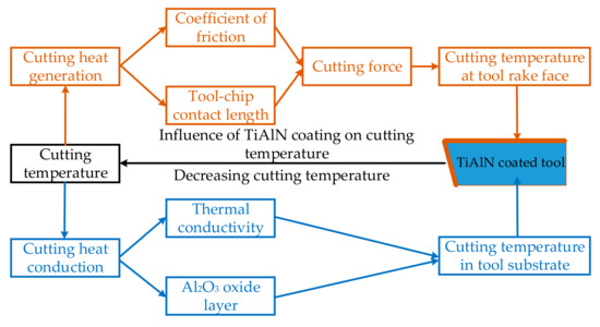
Figure 2.
Research outline for influences of TiAlN coatings on the cutting temperature.
2. Materials and Methods
2.1. Cutting Tools and Workpiece Material
The experimental set-up for the dry orthogonal cutting tests is shown in Figure 3. The cutting tests were carried out on a computer numerical control (CNC) lathe machine (CKD6150H, Dezhou PuLiSen Machine Tool Co. Ltd., Dezhou, China). This CNC turning center was equipped with a spindle power of 7.5 kW and a maximum spindle speed of 1600 rpm.

Figure 3.
Experimental set-up for dry orthogonal cutting.
Uncoated and physical vapor deposition (PVD) TiAlN coated cemented carbide tools with the same geometries designated as NG3125R were used. The rake angle and clearance angle were 0° and 5°, respectively for both of the two kinds of cutting tools. The cutting edge width was 3.18 mm, and the cutting edge radius was 8 μm. The tool holder used in this experiment was NER-2525M3 NK9 (Kennametal, Latrobe, PA, USA). H13 hardened steel with an external diameter of 100 mm and 2 mm disc thickness were used in the cutting tests. The workpiece was fixed by the fixture as presented in Figure 3e. The chemical compositions of H13 hardened steel are presented in Table 1. Metal cutting processes, such as cutting forces, cutting temperature and tool life are affected by the thermal and mechanical properties of workpiece material. The thermal and mechanical properties of H13 hardened steel are shown in Table 2.

Table 1.
Chemical composition of H13 hardened steel [34].
Table 2.
Thermal and mechanical properties of H13 hardened steel [35].
2.2. Metal Cutting Experimental Techniques
The TiAlN coated and uncoated cemented carbide tools share the same cutting parameters. Three different cutting speeds (50, 100, and 150 m/min) were selected. Undeformed chip thickness and cut width were kept constant at 0.015 and 2 mm, respectively.
A three-component piezoelectric dynamometer (Kistler, Winterthur, Germany) was used to measure the tangential cutting force (F). The rake face morphology of new cutting tool was obtained by scanning electron microscope (SEM, Zeiss, Oberkochen, Germany). Then, a laser confocal scanning microscope (LCSM, Keyence, Osaka, Japan) was utilized to observe tool-chip contact length at the tool rake face.
The cutting temperature at the tool-chip contact zone was measured by infrared radiation (IR) thermal imager Ti400 (FLUKE, Everett, WA, USA). An IR thermal imager was mounted at the turning lathe through a designed fixture as shown in Figure 3d. The fixture allowed IR thermal imager to move with any height and angle. IR thermal imager moves with the cutting tool and ensures the measurement area remained unchanged with the aid of the fixture. The temperature measurement system provided for an automatic atmospheric transmission correction of temperature based on input distance from the object, atmospheric temperature and relative humidity. The captured images were analyzed by the SmartView analysis software (version, 3.10, FLUKE, Everett, WA, USA). The cutting temperature at the cutting tool substrate was recorded by K type thermocouple with 0.5 mm diameter. Thermocouple was embedded in the fixed position of cutting tool substrate.
2.3. Friction Tests under High Temperature
Cutting heat generated at tool rake face is mainly affected by the frictional heat at tool-chip interface during metal cutting process. The values of the COF between tool and workpiece material are different at elevated temperature and ambient temperature. Hence, it is necessary to investigate the COF at an elevated temperature. To determine the friction coefficients between cutting tools and H13 hardened steel, friction experiments were conducted on UMT-TriboLab device (Bruker, Billerica, MA, USA). The experimental equipment and experimental conditions are shown in Figure 4.
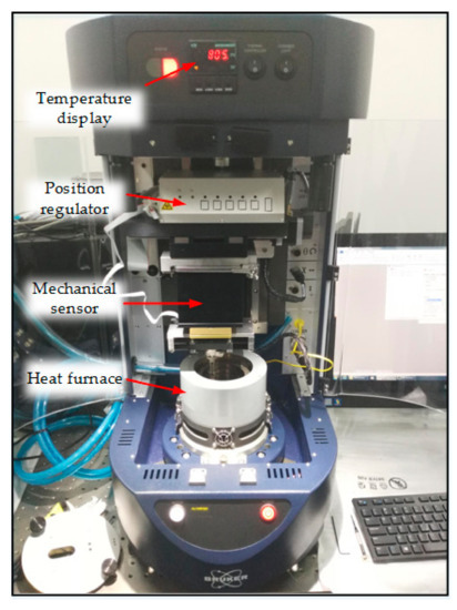
Figure 4.
Experimental equipment of friction coefficient measurement.
In the experiments, test specimens were fixed in the bottom of heat furnace. The cutting tools performed circle rotation movement with certain parameters. The experimental load of the friction tests was 5 N. The temperature was set at 800 °C. Rotation speed and radius of rotation were 200 rpm and 20 mm, respectively. Every friction experiment lasted for 5 min.
3. Results and Discussion
3.1. Influences of TiAlN Coating on Cutting Heat Generation
The cutting heat generated in cutting zone was mainly determined by the plastic work done in the primary deformation zone and the work done to overcoming the sliding friction in the secondary deformation zone. The amount of cutting heat generated in secondary deformation zone could be embodied by the value of tangential cutting force. The tangential cutting forces of the two kinds of cutting tools were shown in Figure 5. In the range of cutting speeds from 50 to 150 m/min, the tangential cutting forces of TiAlN coated cutting tools were smaller than those of uncoated cutting tools. When the cutting speeds increased from 50 to 150 m/min, there was an increase tendency of tangential cutting forces for TiAlN coated cutting tools. However, the tangential cutting forces for uncoated cutting tools were reduced in this cutting speed range.
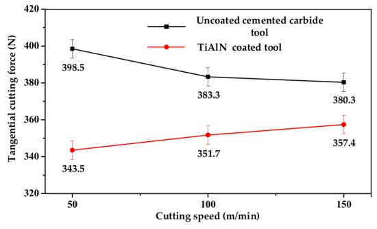
Figure 5.
Variation of tangential cutting forces with cutting speeds.
The tangential cutting force of TiAlN coated tools was smaller than that of uncoated tools. This could be attributed to two reasons. On the one hand, TiAlN coating could reduce the friction between the tool rake face and the chip. On the other hand, the coating was helpful to shorten the contact length between the coated tool and the chip. The values of the COF between tool rake face and H13 hardened steel material at 800 °C are exhibited in Figure 6.
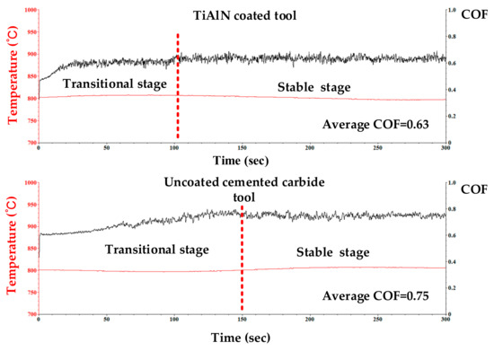
Figure 6.
Values of the COF between cutting tools and workpiece material at 800 °C.
To make the values of the COF more accurately characterize the friction coefficient between cutting tools rake face and chip, the friction tests were investigated at 800 °C instead of at ambient temperature. The curves of the COF with time could be divided into two stages for both of the two kinds of cutting tools, which were transitional and stable stages. It was found that the COF between H13 hardened steel and TiAlN coated tool was smaller than the one between H13 hardened steel and uncoated tool in the stable stage. Compared with uncoated tool, the average value of the COF was reduced by 16% with the TiAlN coating. The average values of the COF for TiAlN coated and uncoated tool were 0.63 and 0.75, respectively.
For the TiAlN coated tool, it took 102 s to reach the stable stage in the friction tests. Meanwhile, it took 150 s for the uncoated cemented carbide tool to reach the stable stage. The TiAlN coated tool reached the stable stage more quickly because its rake face roughness was superior to the cemented carbide tool rake face roughness. The rake face topographies and the surface roughness of the two kinds of cutting tools were presented respectively in Figure 7. The asperities and grooves appeared at the uncoated cemented carbide tool rake face. At the same time, only some particles and pits appeared on the TiAlN coated tool rake face. As shown in Figure 7c,d, the surface roughness of uncoated cemented carbide and TiAlN coated tool were 0.432 and 0.361, respectively.
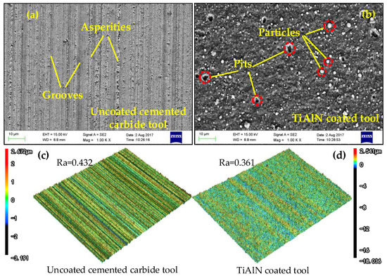
Figure 7.
Surface topographies of tool rake face: (a) surface topographies of cemented carbide tool; (b) surface topographies of TiAlN coated tool; (c) surface roughness of cemented carbide tool; (d) surface roughness of TiAlN coated tool.
Besides providing a smaller value of the COF between the cutting tool rake face and the chip, the shorter tool-chip contact length was also found, which was why the TiAlN coating provided smaller tangential cutting forces. The tool-chip contact lengths were at different cutting speeds, as exhibited in Figure 8. With the cutting speeds increasing, the tool-chip contact length decreased at the TiAlN coated tool rake face. Conversely, the tool-chip contact length increased with the increase of cutting speeds at the uncoated tool rake face. The tool-chip contact length extended from 184 to 244 μm for uncoated tools, when the cutting speeds increased from 50 to 150 m/min. However, the tool-chip contact length shrank from 136 to 108 μm for TiAlN coated tools.
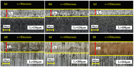
Figure 8.
Variation of tool-chip contact length at tool rake face with cutting speeds, (a–c): TiAlN coated tool; (d–f): uncoated cemented carbide tool.
The contact area between TiAlN coated tool and chip was reduced. Hence, cutting heat generation at the tool-chip contact area was reduced at the same condition. At the same time, shorter tool-chip contact length resulted in shorter tool-chip contact time. The shorter contact time, the less cutting heat conducted into the cutting tools. Reduction of cutting heat that conducted into the cutting tool ensured that the cutting tool maintained a lower cutting temperature and extended the tool life. However, the benefits of reducing the tool-chip contact length were limited. Reduction of the tool-chip contact length would cause the maximum temperature point to move toward the cutting edge. This weakened the edge strength and activated premature cutting tool wear or edge chipping [36].
The shorter tool-chip contact length at TiAlN coated tool rake face compared with uncoated tool could be attributed to the higher hardness of the TiAlN coating at elevated temperature. Figure 9 shown the variation of Vickers micro-hardness with the temperature increased from 25 to 1000 °C for TiAlN coated tool and uncoated cemented carbide tool. The increase of temperature led to the drop of uncoated cemented carbide tool hardness. Meanwhile, the hardness of TiAlN coated tool was almost kept constant in the temperature range from 25 to 900 °C. Then the hardness fell sharply when the temperature increased from 900 to 1000 °C.
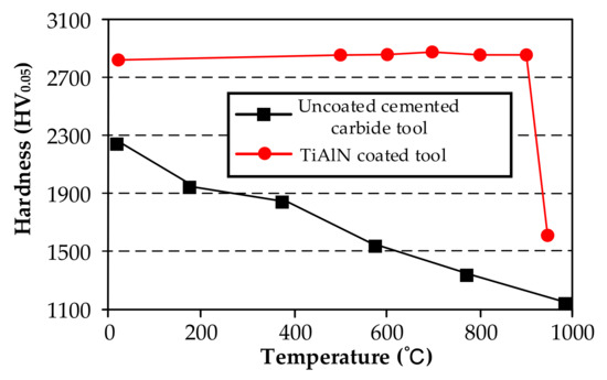
Figure 9.
Hardness of TiAlN coated and uncoated tools at various temperatures. Reprinted with permission from ref. [30]. Copyright 2007. Elsevier.
Due to a shorter tool-chip contact length, the cutting heat generated by overcoming the friction in tool-chip contact area was reduced. Meanwhile, the heat conducted into tool rake face was lessened too. The higher hardness of TiAlN coatings was partly resulted from the solid solution effect of aluminum in the TiN lattice. In addition, the high compressive residual stress contributed to the higher hardness in the TiAlN coatings as well [37].
3.2. Influences of TiAlN Coating on Cutting Heat Conduction
Cutting heat conduction from chip to cutting tool rake face was reduced by the shorter tool-chip contact length. The TiAlN coating also blocked the conduction of cutting heat from tool rake face to tool substrate because of its lower thermal conductivity. Thermal conductivities of cemented carbide and TiAlN coating increased with the rise of temperature from 100 to 900 °C, as demonstrated in Figure 10. In the temperature range, the thermal conductivity of TiAlN coated tool was much smaller than that of uncoated cemented carbide tool. Difference between the two cutting tools’ thermal conductivities was smallest at 100 °C. The thermal conductivities of the two cutting tools at 100 °C were 12.61 and 40.15 W/m·°C, respectively. The difference was amplified with the increase of temperature. When temperature was been increased to 900 °C, the thermal conductivity of TiAlN coating was 18.21 W/m·°C. This value was smaller than that of the uncoated cemented carbide tool. Smaller thermal conductivity resulted in less cutting heat conducting through TiAlN coating into the tool substrate.
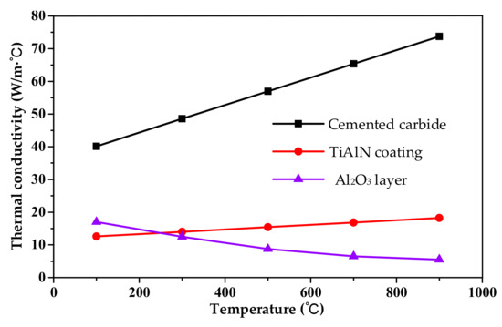
Figure 10.
Variation of thermal conductivities with temperature [24,26,27].
An Al2O3 oxide layer was generated at the TiAlN coated tool rake face during the metal cutting process in this study. Figure 11 exhibits the fracture surface morphology of TiAlN coated tool at the tool-chip contact area at the cutting speed of 50 m/min. It also displays the results of elemental scanning of the cross-section area. Figure 11a demonstrates that the thickness of Al2O3 oxide layer was 0.8 μm. The elemental scanning result shown the oxygen distributed on the top surface of TiAlN coating was significantly larger than that on the substrate of the coating as displayed in Figure 11b. The oxygen element weight percentage and the atomic percentage were revealed by Figure 11c. The values of these percentages were 11.43% and 17.28%, respectively. This further proved the existence of the oxide layer.
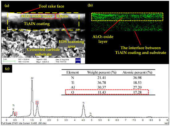
Figure 11.
Fracture surface morphology and elemental scanning of the TiAlN coated tool at cutting speed 50 m/min: (a) SEM image of fracture cross-section of TiAlN coated tool; (b) oxygen elemental scanning of TiAlN coated tool; (c) weight percent and atomic percent of the elements.
Due to lower thermal conductivity, the TiAlN coating impeded the cutting heat from conducting into the cutting tool. Furthermore, the Al2O3 oxide layer generated at the tool rake face also hindered the cutting heat from entering the cutting tool. Figure 10 illustrates the decreased thermal conductivity of the Al2O3 coating layer with the increase of temperature. The thermal conductivity of Al2O3 coating layer fell from 17 W/m·°C at 100 °C to 5.5 W/m·°C at 900 °C. Lower thermal conductivity resulted in less cutting heat being conducted into the cutting tool. Therefore, both the Al2O3 oxide layer and the TiAlN coating acted as thermal barriers during cutting heat conducting from the tool rake face into the cutting tool substrate. They guaranteed that the TiAlN coated tool maintained a lower cutting temperature and better hardness during the metal machining process.
3.3. Cutting Temperature
The maximum cutting temperature in the cutting zone was measured by infrared radiation (IR) thermal imager FLUKE Ti400. Figure 12 presented the infrared photograph of cutting temperature distribution at cutting speed of 50 m/min for the TiAlN coated tool. The point of maximum cutting temperature located near the cutting edge of the tool rake face. The accuracy of measured temperature depended strongly on the surface thermal emissivity of the object being measured. Considering the oxidation of the TiAlN coating, average thermal emissivity of TiAlN coated tool rake face in this study was set as 0.43 with thermocouple calibration. And the uncoated cemented carbide tool was determined to be 0.47.
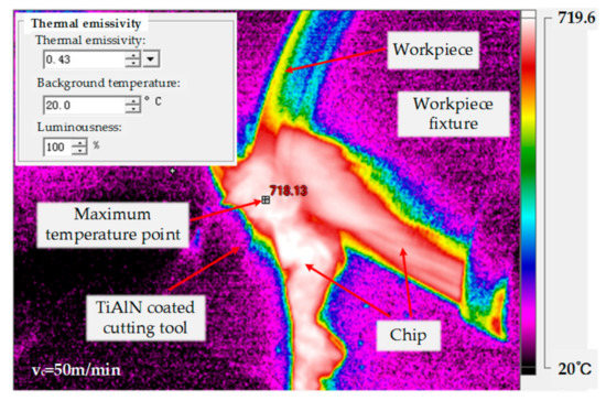
Figure 12.
Infrared photograph of cutting temperature distribution for TiAlN coated tool at cutting speed 50 m/min.
Figure 13 exhibited the maximum cutting temperature in the cutting speed range from 50 to 150 m/min for uncoated cemented carbide tools and TiAlN coated tools. As the cutting speed increased, the maximum cutting temperatures were increased for both of the cutting tools. Comparing the maximum cutting temperature of the two kinds of cutting tools under the same cutting parameters, it was found that the temperature of the uncoated cemented carbide tool was higher than that of the TiAlN coated tool. The difference of maximum temperature between the two kinds of cutting tools was increased with the increase of the cutting speed. At the speed of 50 m/min, the maximum cutting temperature of TiAlN coated tool was 51 °C lower than that of the uncoated cemented carbide tool. With the growth of the cutting speed, the difference of maximum cutting temperature was amplified to 78 °C at 100 m/min and 168 °C at 150 m/min.
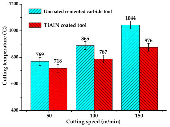
Figure 13.
The maximum cutting temperatures at various cutting speeds.
K type thermocouples were utilized to measure the cutting temperatures in the cutting tool substrate. The holes used to set thermocouples in the cutting tools substrate were obtained by electrical discharge machining. The temperature data measured by thermocouples during the cutting experiments were recorded by the specific equipment. After the cutting experiments, tools with the same thermocouple location were selected and their corresponding cutting temperature data were analyzed. The evolutions of cutting temperature versus cutting time are reported in Figure 14.
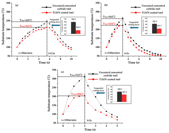
Figure 14.
Variations of cutting temperature and tangential cutting force with various cutting speeds: (a) variations of cutting temperature and tangential cutting force at 50 m/min; (b) variations of cutting temperature and tangential cutting force at 100 m/min; (c) variations of cutting temperature and tangential cutting force at 150 m/min.
At same cutting speed, the two kinds of cutting tools substrate cutting temperature trends were basically the same. However, the cutting temperature of the TiAlN coated tool was lower than that of the uncoated cemented carbide tool. When the cutting speed was 50 m/min, the maximum cutting temperature of the TiAlN coated tool was 33 °C lower than that of the uncoated cemented carbide tool. The difference of tool substrate cutting temperature between the two kinds of cutting tools was expanded with the increase of cutting speed. The values of substrate cutting temperature difference augmented to 38 °C at 100 m/min and 108 °C at 150 m/min.
Lower cutting temperature of TiAlN coated tools could be attributed to the following reasons. From the tribological point of view, TiAlN coating reduced the value of the COF between the tool rake face and the chip. In addition, TiAlN coating shortened the tool-chip contact length. Therefore, the cutting heat was decreased due to the lower COF and the shorter tool-chip contact length. The shorter tool-chip contact length also lessened the cutting heat conduction from the chip into the tool rake face. When the cutting heat conducted from the tool rake face into the cutting tool substrate, the Al2O3 oxide layer generated on the tool rake face and the TiAlN coating acted as thermal barriers because of their lower thermal conductivities. As a result, the TiAlN coated tool maintained a lower cutting temperature and better rigidity during the H13 hardened steel machining process.
4. Conclusions
TiAlN coating reduced the cutting heat generation by decreasing the tangential cutting force. Comparing with uncoated cemented carbide tools, the smaller tangential cutting forces were attributed to the smaller COF between the tool rake face and the workpiece material. Furthermore, the TiAlN coating shortened the tool-chip contact length. A shorter tool-chip contact length resulted in a smaller tangential cutting force.
The values of the COF between cutting tools and workpiece material were obtained at 800 °C. The TiAlN coating reduced the value of the COF by 16% compared with an uncoated cemented carbide tool. Better surface roughness and better high temperature hardness led to a smaller COF between the TiAlN coating and H13 hardened steel.
During the metal cutting process, the Al2O3 oxide layer was generated at the tool rake face. The oxide layer appeared at the tool-chip contact zone. The thickness of the oxide layer was 0.8 μm. The thermal conductivities of the TiAlN coating and the Al2O3 oxide layer were much smaller than that of the uncoated cemented carbide. Therefore, the TiAlN coating and Al2O3 oxide layer acted as the thermal barrier role. They prevented cutting heat conducting from the tool rake face to the tool substrate. The TiAlN coating made the cutting tools maintain a lower cutting temperature, better hardness and better stiffness during the metal cutting process.
Author Contributions
Conceptualization, G.H. and Z.L.; Methodology, G.H. and Z.L.; Investigation, G.H., X.L. and J.Z.; Resources, G.H.; Writing—Original Draft Preparation, G.H.; Writing—Review and Editing, G.H., Z.L., X.L. and J.Z.; Funding Acquisition, Z.L.
Funding
This research was funded by National Science Foundation of China (grant numbers 51425503 and 91860207), and Taishan Scholar Foundation of Shandong Province (grant number TS 20130922), and the National Key Research and Development Program of China (grant number 2018YFB2002201).
Acknowledgments
The authors would like to acknowledge the technical support of the Collaborative Innovation Center for Shandong’s Main Crop Production Equipment and Mechanization.
Conflicts of Interest
The authors declare no conflict of interest.
References
- Chen, L.; Du, Y.; Mayrhofer, P.H.; Wang, S.Q.; Li, J. The influence of age-hardening on turning and milling performance of Ti–Al–N coated inserts. Surf. Coat. Technol. 2008, 202, 5158–5161. [Google Scholar] [CrossRef]
- Chen, L.; Du, Y.; Wang, S.Q.; Li, J. A comparative research on physical and mechanical properties of (Ti,Al)N and (Cr,Al)N PVD coatings with high Al content. Int. J. Refract. Met. Hard Mater. 2007, 25, 400–404. [Google Scholar] [CrossRef]
- Chen, L.; Moser, M.; Du, Y.; Mayrhofer, P.H. Compositional and structural evolution of sputtered Ti–Al–N. Thin Solid Films 2009, 517, 6635–6641. [Google Scholar] [CrossRef]
- Huang, L.; Chen, J.C.; Chang, T. Effect of tool/chip contact length on orthogonal turning performance. J. Ind. Technol. 1999, 15, 1–5. [Google Scholar]
- PalDey, S.; Deevi, S.C. Single layer and multilayer wear resistant coatings of (Ti, Al) N: A review. Mater. Sci. Eng. A 2003, 342, 58–79. [Google Scholar] [CrossRef]
- Rech, J.; Kusiak, A.; Battaglia, J.L. Tribological and thermal functions of cutting tool coatings. Surf. Coat. Technol. 2004, 186, 364–371. [Google Scholar] [CrossRef]
- Chen, L.; Paulitsch, J.; Du, Y.; Mayrhofer, P.H. Thermal stability and oxidation resistance of Ti–Al–N coatings. Surf. Coat. Technol. 2012, 206, 2954–2960. [Google Scholar] [CrossRef]
- Abukhshim, N.A.; Mativenga, P.T.; Sheikh, M.A. Heat generation and temperature prediction in metal cutting: A review and implications for high speed machining. Int. J. Mach. Tools Manuf. 2006, 46, 782–800. [Google Scholar] [CrossRef]
- Grzesik, W.; Rech, J.; Żak, K. Determination of friction in metal cutting with tool wear and flank face effects. Wear 2014, 317, 8–16. [Google Scholar] [CrossRef]
- Ozlu, E.; Budak, E.; Molinari, A. Analytical and experimental investigation of rake contact and friction behavior in metal cutting. Int. J. Mach. Tools Manuf. 2009, 49, 865–875. [Google Scholar] [CrossRef]
- Bahi, S.; Nouari, M.; Moufki, A.; El Mansori, M.; Molinari, A. Hybrid modelling of sliding-sticking zones at the tool-chip interface under dry machining and tool wear analysis. Wear 2012, 286, 45–54. [Google Scholar] [CrossRef]
- Rech, J. Influence of cutting tool coatings on the tribological phenomena at the tool-chip interface in orthogonal dry turning. Surf. Coat. Technol. 2006, 200, 5132–5139. [Google Scholar] [CrossRef]
- Balaji, A.K.; Mohan, V.S. An effective cutting tool thermal conductivity based model for tool-chip contact in machining with multi-layer coated cutting tools. Mach. Sci. Technol. 2002, 6, 415–436. [Google Scholar] [CrossRef]
- Grzesik, W.; Nieslony, P. A computational approach to evaluate temperature and heat partition in machining with multilayer coated tools. Int. J. Mach. Tools Manuf. 2003, 43, 1311–1317. [Google Scholar] [CrossRef]
- Fahad, M.; Mativenga, P.T.; Sheikh, M.A. Critical design factors for multi-layer coating systems that influence heat partition in the secondary shear deformation zone and machining performance. Proc. Inst. Mech. Eng. Part B J. Eng. Manuf. 2012, 226, 1071–1085. [Google Scholar] [CrossRef]
- Binder, M.; Klocke, F.; Doebbeler, B. Abrasive wear behavior under metal cutting conditions. Wear 2017, 376, 165–171. [Google Scholar] [CrossRef]
- Grzesik, W. Friction behaviour of heat isolating coatings in machining: Mechanical, thermal and energy-based considerations. Int. J. Mach. Tools Manuf. 2003, 43, 145–150. [Google Scholar] [CrossRef]
- Mo, J.L.; Zhu, M.H.; Lei, B.; Leng, Y.X.; Huang, N. Comparison of tribological behaviours of AlCrN and TiAlN coatings-Deposited by physical vapor deposition. Wear 2007, 263, 1423–1429. [Google Scholar] [CrossRef]
- Mo, J.L.; Zhu, M.H. Tribological oxidation behaviour of PVD hard coatings. Tribol. Int. 2009, 42, 1758–1764. [Google Scholar] [CrossRef]
- Liu, A.H.; Deng, J.X.; Cui, H.B.; Chen, Y.Y.; Zhao, J. Friction and wear properties of TiN, TiAlN, AlTiN and CrAlN PVD nitride coatings. Int. J. Refract. Met. Hard Mater. 2012, 31, 82–88. [Google Scholar] [CrossRef]
- Jiang, F.; Yan, L.; Rong, Y.M. Orthogonal cutting of hardened AISI D2 steel with TiAlN-coated inserts-simulations and experiments. Int. J. Adv. Manuf. Technol. 2013, 64, 1555–1563. [Google Scholar] [CrossRef]
- Friedman, M.Y.; Lenz, E. Investigation of the tool-chip contact length in metal cutting. Int. J. Mach. Tool Des. Res. 1970, 10, 401–416. [Google Scholar] [CrossRef]
- Balaji, A.K.; Sreeram, G.; Jawahir, I.S.; Lenz, E. The effects of cutting tool thermal conductivity on tool-chip contact length and cyclic chip formation in machining with grooved tools. CIRP Ann. Manuf. Technol. 1999, 48, 33–38. [Google Scholar] [CrossRef]
- Fahad, M.; Mativenga, P.T.; Sheikh, M.A. On the contribution of primary deformation zone-generated chip temperature to heat partition in machining. Int. J. Adv. Manuf. Technol. 2013, 68, 99–110. [Google Scholar] [CrossRef]
- Abukhshim, N.A.; Mativenga, P.T.; Sheikh, M.A. An investigation of the tool-chip contact length and wear in high-speed turning of EN19 steel. Proc. Inst. Mech. Eng. Part B J. Eng. Manuf. 2004, 218, 889–903. [Google Scholar] [CrossRef]
- Akbar, F.; Mativenga, P.T.; Sheikh, M.A. An evaluation of heat partition in the high-speed turning of AISI/SAE 4140 steel with uncoated and TiN-coated tools. Proc. Inst. Mech. Eng. Part B J. Eng. Manuf. 2008, 222, 759–771. [Google Scholar] [CrossRef]
- Akbar, F.; Mativenga, P.T.; Sheikh, M.A. On the heat partition properties of (Ti, Al) N compared with TiN coating in high-speed machining. Proc. Inst. Mech. Eng. Part B J. Eng. Manuf. 2009, 223, 363–375. [Google Scholar] [CrossRef]
- Akbar, F.; Mativenga, P.; Sheikh, M. Heat partition-based design of hard coatings in high-speed machining. Int. J. Mach. Mach. Mater. 2013, 14, 363–386. [Google Scholar] [CrossRef]
- Kong, D.J.; Guo, H.Y. Analysis of structure and bonding strength of AlTiN coatings by cathodic ion plating. Appl. Phys. A 2015, 119, 309–316. [Google Scholar] [CrossRef]
- Coelho, R.T.; Ng, E.G.; Elbestawi, M.A. Tool wear when turning hardened AISI 4340 with coated PCBN tools using finishing cutting conditions. Int. J. Mach. Tools Manuf. 2007, 47, 263–272. [Google Scholar] [CrossRef]
- Xu, Y.X.; Chen, L.; Yang, B.; Peng, Y.B.; Du, Y.; Feng, J.C.; Pei, F. Effect of CrN addition on the structure, mechanical and thermal properties of Ti–Al–N coating. Surf. Coat. Technol. 2013, 235, 506–512. [Google Scholar] [CrossRef]
- Chen, L.; Yang, B.; Xu, Y.X.; Pei, F.; Zhou, L.C.; Du, Y. Improved thermal stability and oxidation resistance of Al–Ti–N coating by Si addition. Thin Solid Films 2014, 556, 369–375. [Google Scholar] [CrossRef]
- Grzesik, W.; Bartoszuk, M.; Nieslony, P. Finite difference analysis of the thermal behaviour of coated tools in orthogonal cutting of steels. Int. J. Mach. Tools Manuf. 2004, 44, 1451–1462. [Google Scholar] [CrossRef]
- Koneshlou, M.; Asl, K.M.; Khomamizadeh, F. Effect of cryogenic treatment on microstructure, mechanical and wear behaviors of AISI H13 hot work tool steel. Cryogenics 2011, 51, 55–61. [Google Scholar] [CrossRef]
- Ng, E.G.; Aspinwall, D.K.; Brazil, D.; Monaghan, J. Modelling of temperature and forces when orthogonally machining hardened steel. Int. J. Mach. Tools Manuf. 1999, 39, 885–903. [Google Scholar] [CrossRef]
- Fahad, M.; Mativenga, P.T.; Sheikh, M.A. An investigation of multilayer coated (TiCN/Al2O3-TiN) tungsten carbide tools in high speed cutting using a hybrid finite element and experimental technique. Proc. Inst. Mech. Eng. Part B J. Eng. Manuf. 2011, 225, 1835–1850. [Google Scholar] [CrossRef]
- Jindal, P.C.; Santhanam, A.T.; Schleinkofer, U.; Shuster, A.F. Performance of PVD TiN, TiCN, and TiAlN coated cemented carbide tools in turning. Int. J. Refract. Met. Hard Mater. 1999, 17, 163–170. [Google Scholar] [CrossRef]
© 2019 by the authors. Licensee MDPI, Basel, Switzerland. This article is an open access article distributed under the terms and conditions of the Creative Commons Attribution (CC BY) license (http://creativecommons.org/licenses/by/4.0/).