Article

Experiment Study of Rapid Laser Polishing of Freeform Steel Surface by Dual-Beam

School of Intelligent Manufacturing and Equipment, Shenzhen Institute of Information Technology, Shenzhen 518172, China
*
Author to whom correspondence should be addressed.
Coatings 2019, 9(5), 324; https://doi.org/10.3390/coatings9050324
Submission received: 28 April 2019 / Revised: 11 May 2019 / Accepted: 13 May 2019 / Published: 16 May 2019
(This article belongs to the Special Issue Surface Treatment by Laser-Assisted Techniques)

Abstract

:
One of the challenges regarding widespread use of parts made from alloy steel is their time-consuming polishing process. A rough freeform surface of part has been often expected to be polished rapidly up to a smooth surface finish. The focus of this study is to develop a fast polishing method of freeform surface by using dual-beam lasers. The dual-beam laser system consists of continuous laser (CW) and pulsed laser based on a five-axis CNC device. In this study, a series of experiments of CW laser polishing present the effects of different spot irradiation on surface topography, then the combination trajectory of zigzag and square waveform of pulsed laser is explored to realize a “melting peak for filling into valley” (MPFV) method. The polishing experiment on a semisphere of S136H steel polished by dual-beam shows that a rough semisphere surface was rapidly polished from initial state value of Sa (=877 nm) to post-polished value of Sa (=142 nm), and the polishing efficiency is as high as 2890 cm2/H.

1. Introduction

Freeform surface plays significant role of enhancing functional and aesthetical properties of products. The increasing demand for parts with free-form surfaces in aerospace, communications, energy, mold making, kitchenware and medicine requires that polishing technology provides excellent surface finish in high efficiency. Current automated polishing techniques often cannot be used on parts with freeform surfaces and functional relevant edges, therefore the finishing for these parts is often done manually [1,2]. Due to the low polishing efficiency (typically maximum 30 cm2/H from initial state value of Sa (=877 nm) to post-polished value of Sa (=142 nm) by a skilled worker, it is often expected that the time consuming polishing process should be replaced by an innovative rapid one.
One new approach to automate this work is rapidly polishing by means of laser radiation. This is why, in recent years, laser polishing has become more widely used due to the ability to quickly and efficiently polish surfaces [3]. Besides metal, laser is able to polish non-metal materials, ultrafast lasers have been used to produce complex shapes in glass [4] while CW lasers have been used for polishing them with extremely low surface roughness [5]. In polishing process, laser is melting a thin surface layer, melted material flows from the peaks to the valleys due to the surface tension, to evenly distribute the recently melted material across the surface and thus creating a much smoother surface finish [6]. Typical roughness after laser polishing are in the range of Sa (150–512 nm), which meets the medium demand on surface quality of a large number of parts in many industrial fields.
Most researchers are focusing on the study of laser polishing of flat surface of workpiece; however, due to the existence of difference of the surface tension of melted pool between flat surface and freeform surface, a new approach to attenuate longer spatial wavelengths of freeform surface is often asked for.

2. CW Laser Polishing

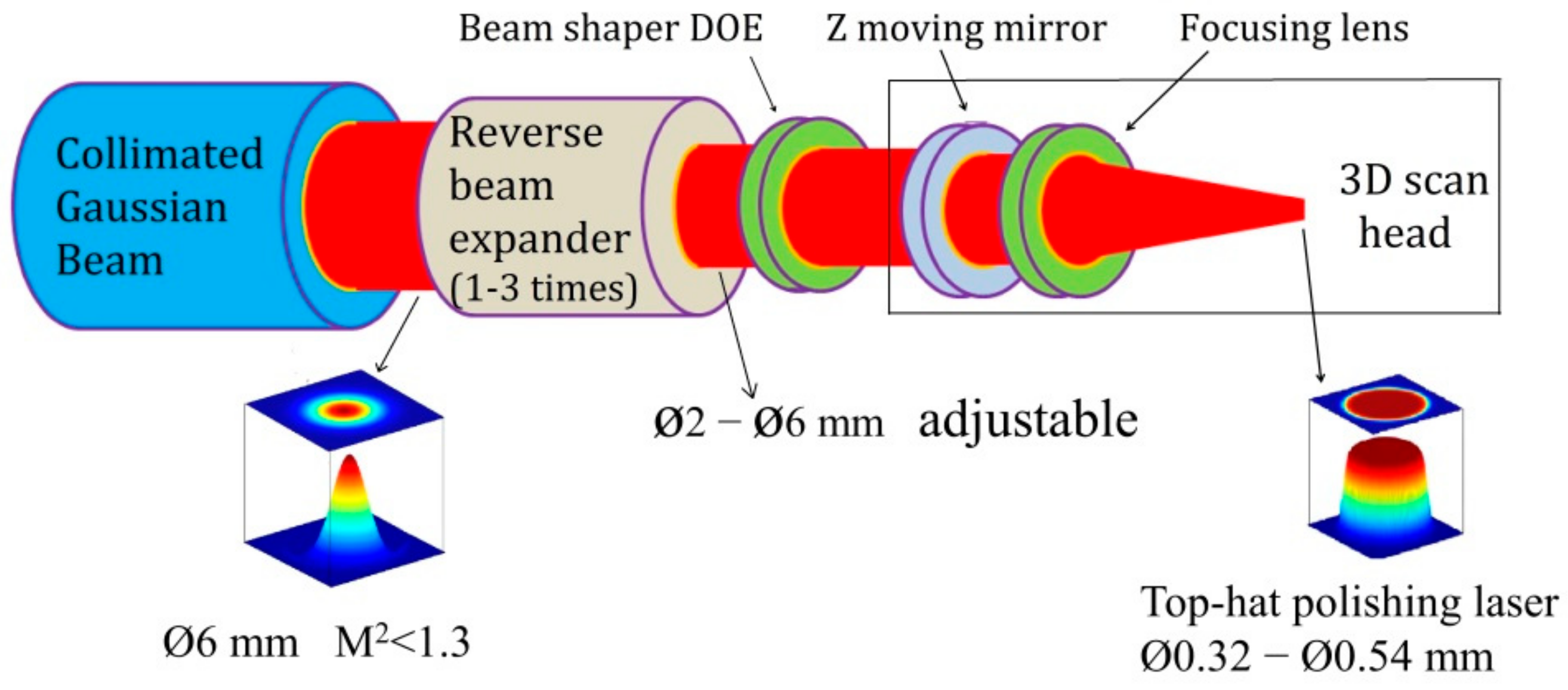
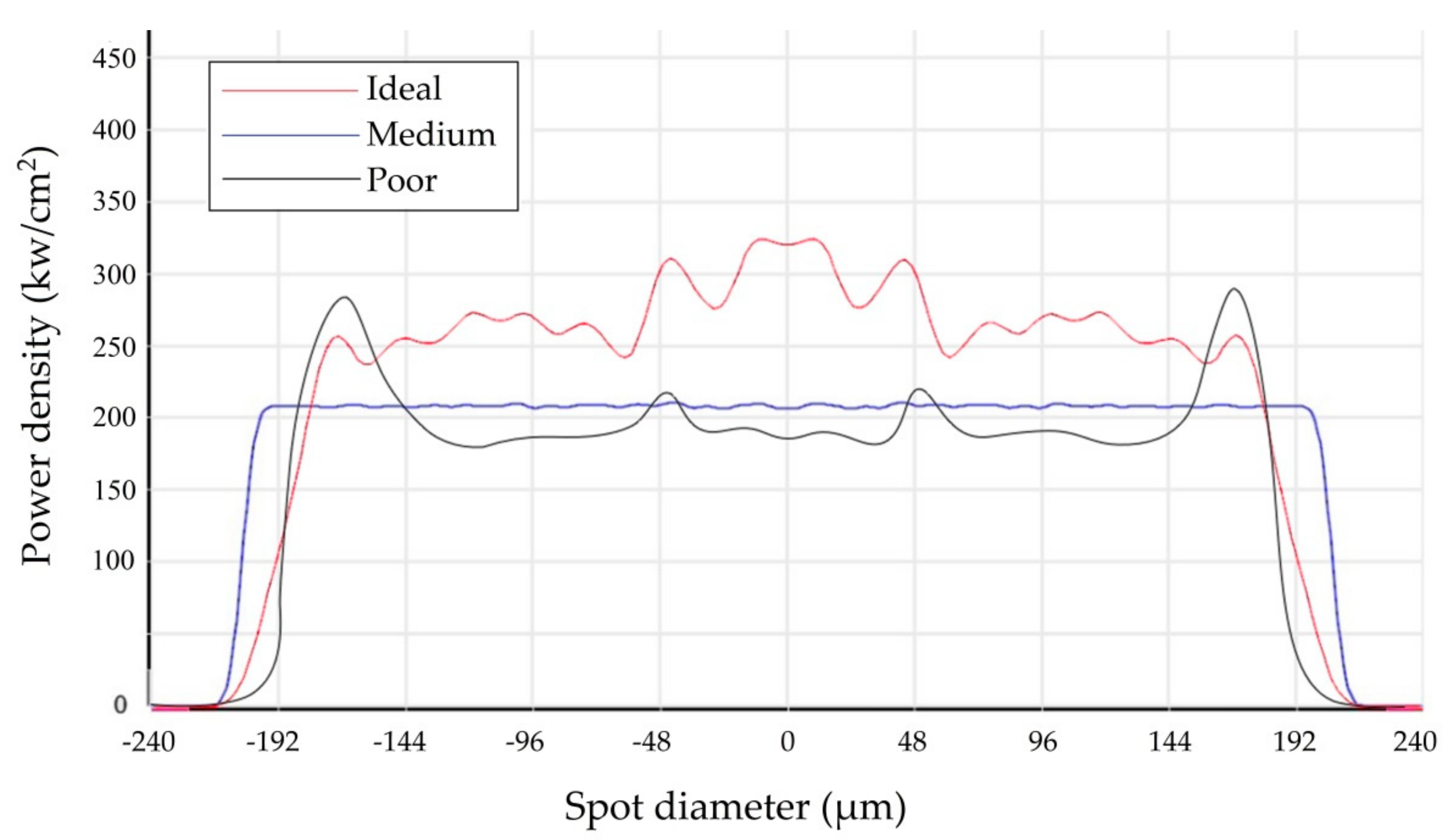
2.1. CW Laser Beam Profile Pattern

The dual-laser polishing system consists of CW laser and pulsed laser. First of all, the performance of CW laser polishing should be studied. Laser polishing differs from more widely known techniques of laser engraving and laser ablation in that it is an equating process, no adding material or removing material as in those techniques. The profile pattern of CW laser beam from the laser generator is Gaussian beam instead of top-hat beam, where the spot is circular but with a uniform intensity profile [7]. A Gaussian beam results in a non-uniform process that polishes some areas of the panel more effectively than others, due to the differences in their thermal cycles. To avoid any ablation on polished surface, the laser beam must be a top-hat beam rather than a Gaussian beam, so that the power density of the spot can be uniform to ensure no any material is vaporized in the molten pool. Meanwhile, there are several parameter factors to influence the surface quality during CW laser polishing. Previous works respectively explored using the parameters such as power density, scanning speed, scanning line step-over, scan trajectories during CW laser polishing for improved surface finish [1,6,8,9].
The spot irradiation of CW laser is a critical factor in CW laser polishing process; however, its effect was rarely introduced in previous works since it was often fixed. In the experiment study, as shown in Figure 1, a combined system consisting of a reverse beam expander and a beam shaper was established, which does not just convert a Gaussian beam into a top-hat beam, but also realizes stepless adjustment of spot diameter from 0.32 to 0.54 mm, thus realizing the adjustment of the spot irradiation. Ideally, the smaller the M2 value of initial CW Gaussian beam, the more uniform the distribution of spot irradiation of converted top-hat beam.
High quality of the beam profile of CW laser plays a key role in the process optimization. To portray the degree of uniform intensity of beam profiles, three patterns of top-hat beam profile are marked by “Ideal”, “Medium” and “Poor” respectively, and given in Figure 2 regarding to the setup of diameter ø0.47 mm of the top-hat beam. The “Ideal” beam pattern has a lowest irregularity figure, in order not to introduce wave-front errors which would degrade the beam shaper performance. The quality of top-hat beam profile is depended on many factors such as mirror’s flatness specification, M2 value of input Gaussian beam, the laser waist position where the beam shaper element works [10]. The degree of irregularity increases from “Medium” beam pattern to “Poor” one since some regions overheat compared to other regions.

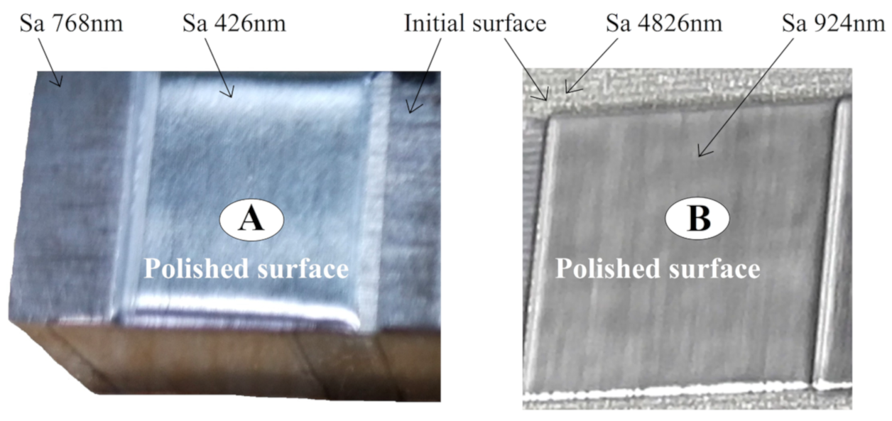
2.2. CW Laser Polishing Using Different Sopt Diameters

A large number of cores/cavities of translucent plastic injection mold are made of S136H steel, the surface of cores/cavity often needs to be polished to Sa < 190nm or even lower. Thus, the first focus of this study will be to generate more comprehensive understanding of surface quality of CW laser polishing S136H steel with different spot irradiation. Four groups of specimens of ground flat S136H tool steel (10 mm thickness) were prepared. Each group had 9 specimens with different initial roughness, ranging from Sa (=768 nm) to Sa (=4826 nm). To portray the effects that the beam spot irradiation have on area polishing, a rough polishing experiment was conducted using a CW laser by the adjustment of spot irradiation from 262–746 kw/cm2 based on the reverse beam expander as shown in Figure 1. Each group was polished with different spot irradiation as shown in Table 1.
Except the spot irradiation and scanning speed, the surface polishing strategy was similar to previous works [11,12,13], and the polishing parameters were optimized and given in Table 2. To polish rapidly, the scanning speed was setup over 600% higher than previous works [3,14].
Total 36 specimens were polished, each specimen was polished more than 3 times in different regions in order to make an error bar of roughness measurement. The surface measurements were taken of the ground and laser polished surfaces using a white light interferometer (BRUKER WYKO Contour GT-K, Billerica, MA, USA). Figure 3 shows the roughness of the laser polished surfaces corresponding to each initial rough ground flat surface with the varying spot irradiation. Point C’s error bar with scale is shown in Figure 2 to reveal the difference of roughness measured by polishing in different regions of a specimen. Point A and Point B present the minimum roughness and maximum roughness obtained among the 36 polished specimens and the results are shown in Figure 3 and Figure 4.
The CW laser polishing process was able to achieve a surface roughness reduction from 44%–81%, resulting in the areal surface roughness dropping from its initial state value of Sa (=4826 nm) to a final post-polished value of Sa (=924 nm).
Figure 3 reveals the fact that an appropriate spot irradiation is one of key factors to influence the surface finish when CW laser is polishing a steel surface in high efficiency. Obviously, 346 kw/cm2 is the optimized value of spot irradiation in the experiment. The ablation or evaporation occurred in the melted pool when the spot irradiation is over 477 kw/cm2, so that the roughness of polished surface is higher than that of polished surface on which the spot irradiation (≤346 kw/cm2) was applied.

3. Experiment of Dual-Beam Laser Polishing

In laser polishing process, many aspects of the research surrounding the topic remain focused on process optimization to achieve finish surface. Often, when experimenting with the optimization of laser polishing parameters (power density, scanning speed, spot diameter, etc.), a so-called “melting peak for filling into valley” (MPFV) method is implemented. The MPFV method consists of melting a series of peaks of topography of surface independent of one another, each flowing into adjacent valleys by surface tension of melted pool.
Nüsser et al. [15] has developed a dual-laser system in which the CW laser was to pre-heat the surface as high as possible without melting the surface, the pulsed laser implemented MPFV method to polish the surface.
In the experiment study, the CW laser not only pre-heats the surface but also roughly polishes the surface. To achieve this, experiments will be conducted using MPFV method with dual-beam lasers and an innovation of trajectory of pulsed laser will be analyzed.
Hafiz et al. [8] and Nüsser et al. [15] have investigated that a combined CW and pulse laser polishing as a two-step process on various alloy melts and shown to improve the surface finish. However, such previous works focused on the polishing of ground flat surface rather than freeform surface. In the investigation, a dual-beam laser polishing system has been developed to implement the MPFV method for freeform surface.

3.1. Dual-Beam Laser Polishing Device

A diagram of the experimental setup of the dual-beam laser polishing system is given in Figure 5. The system is composed of two 3D scan heads and a 2-axis CNC rotation table. A CW laser beam, which is reshaped from Gaussian beam to top-hat beam (Figure 1), enters a Z moving lens and focusing lens of the first 3D scan head. A pulsed laser beam with top-hat profile pattern from a laser generator directly enters a Z moving lens and focusing lens of the second 3D scan head. Taking for example of first 3D scan head, after moving lenses, the CW laser beam diverges rapidly until it enters one or two focusing lenses. The beam, now converging, passes through and is directed by a set of X and Y mirrors moved. The orthogonal arrangement of the X and Y mirrors direct the beam down towards and over the length and width of the working field. The focusing height of laser is adjusted by moving Z lens according to the Z coordinates of 3D surface model. The 3D freeform surface is activated by the laser beam, the maximum angle of incidence of the laser beam on the surface to be machined must not be exceeded if safe activation is to be achieved. The angle of incidence is the angle between the orthogonal to the activated surface and the laser beam. Usually the maximum angle of incidence is no bigger than 30°, so that some tilted surfaces are out of its machining scope, therefore a 2D rotation table is needed to make sure any tilted surface could be machined by its rotation. The system is able to move internal laser beam in three primary axes, designated X , Y , Z , and another two axes created by the rotation of the x and y-axes, designed A , C , therefore five CNC axes are X , Y , Z , A , C respectively. Figure 6 is the five-axis CNC device with dual-beam system. The motion in the five axes should be synchronized in order to achieve predictable 3D polishing trajectories of the beam focus.
The above experiment indicates that CW laser polishing is of high polishing efficiency since the scanning speed is over 800 mm/s, but the polished surface roughness did not reach to Sa < 400nm. To achieve the advantage of both high polishing efficiency and smoother surface finish, pulsed laser micro polishing (PLμP) is conducted to implement the MPFV Method.
Figure 7 is the topography of the specimen marked “A” in Figure 4. Ukar et al. [16] showed that due to a series of surface irregularities in the melted pool, there are zones with greater amounts of material, which when melted generate areas of higher surface tension. This surface tension tends to eliminate the irregularities within the melted area, producing material displacement into the melt pool. In other words, the surface tension becomes depreciated, resulting in the poor performance of eliminating the irregularities during CW laser polishing process with high scanning speed (800 mm/s) in that peak region shown in Figure 7 is not capable of fully filling into the valleys adjacent and surrounding to itself, therefore the melted peak is cooled and solidified rapidly during MPFV process, forming a new series of smaller peaks (red areas in Figure 7).

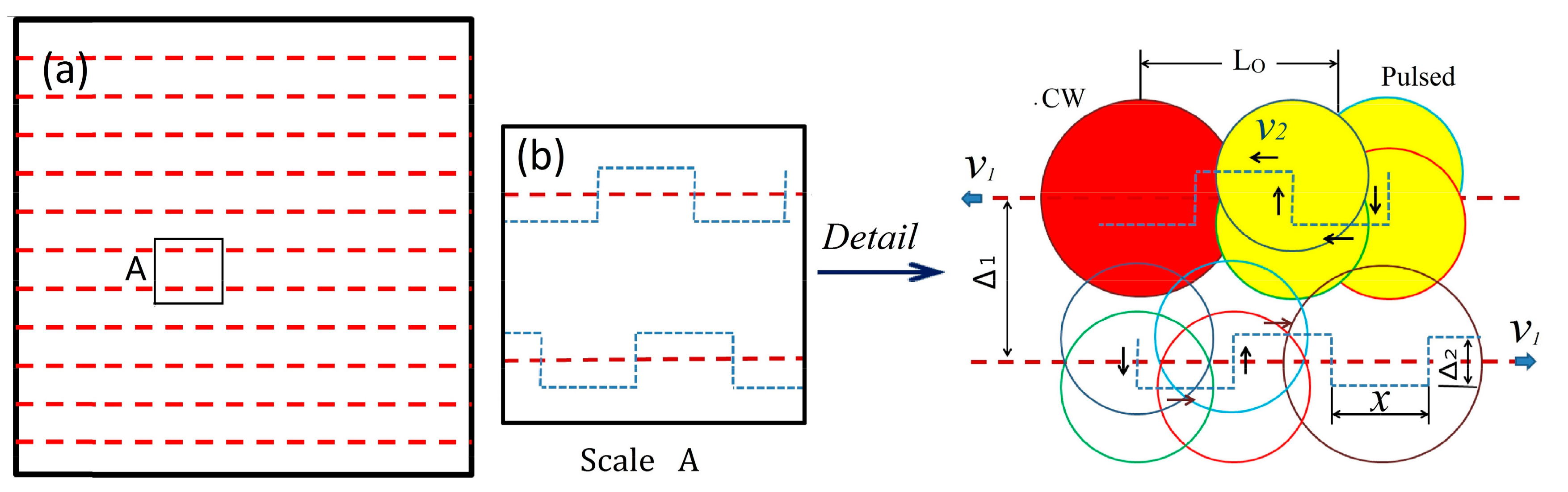
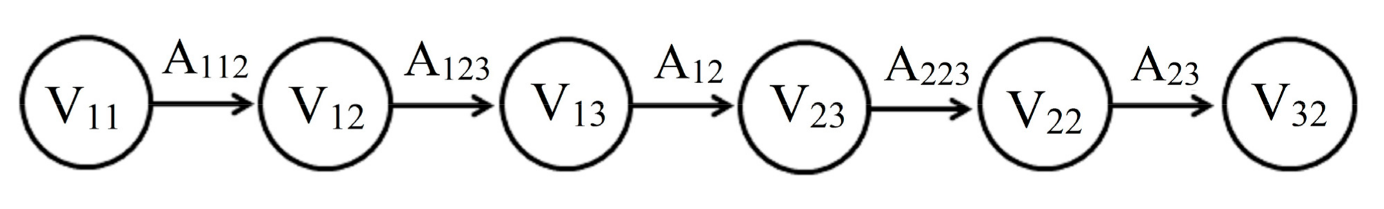
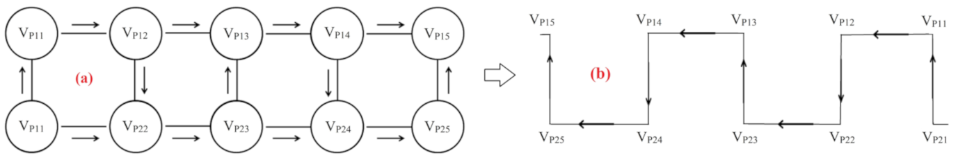
3.2. Trajectory of Zigzag-Square Wave of Dual-Beam

PLμP is capable of achieving significant surface smoothing quickly without removing material, and promotes the migration of molten pool materials, since it melts a metallic surface and allows surface tension effects to smooth the surface [17]. PLμP is a helpful tool to implement the MPFV method. In dual-beam laser polishing system, the pulsed laser follows up with the CW laser closely with a certain level of overlap. The new peak which is formed during CW laser polishing process, will not be solidified immediately since the pulsed laser beam is following up with it and making the new peak re-melted instead. A very smaller layer of material creating a smaller molten pool, which uses the physics of surface tension, evenly distributes the recently re-melted material across the surface, and creates much smoother surface finish.
Figure 7 indicates that the peaks formed during CW laser polishing exist in both transverse and longitudinal directions. To improve the MPFV performance of PLμP, the pulsed laser should alternately move along the transverse and longitudinal directions in order to mitigate the peaks to adjacent valleys in the two directions. Therefore a combination trajectory of zigzag and square waveform of the pulsed laser is proposed, zigzag is the path for pulsed laser to follow up with CW laser, and the square wave is the path for pulsed laser to mitigate the peaks to adjacent valleys in the transverse and longitudinal directions. The trajectories of dual-beam are figured out in Figure 8. Δ1 is the step-over of the CW laser, Δ2 is that of the pulsed laser, and LO is the overlap between both beams.
The trajectory of CW laser is zigzag [3], and that of pulsed laser is the combination of zigzag and square wave. x is a half wavelength of the square wave. Nüsser et al. [15] has concluded that an appropriate overlap LO led to the smallest micro roughness, so the range of 2 x L O 3 x was set up in the experiment, excessive LO value makes the new peak solidified in advance of the pulsed laser working and weakens the surface tension of melted pool.
Both scanning speeds must match with each other to keep the overlap LO in above range. If the scanning speed of CW laser is v1 that of pulsed laser is v2, then,
( 1 + 2 Δ 2 3 x ) v 1 v 2 ( 1 + Δ 2 x ) v 1
The zigzag trajectory is a common practice in laser processing [3,18]; however, the pulsed laser is following up with the CW laser with its own square wave route besides the zigzag trajectory, its route network should be optimized individually.
According to the route network optimization of previous works [19,20], the offset contours of laser scanning trajectory are marked in four directions, which are from left to right, from right to left, from top to bottom and from bottom to top, and the endpoints and intersections are connected in turn. Both the endpoints and intersections of the contour form the vertices Vi of the route network, both the length of the line segment and the arc between the connections form the arc length Ai. A laser polishing track is connected from the beginning to the end. Based on the Dijkstra algorithm [20,21], V11, V12, V13, V23, V22, V32 are the effective path vertices, which form the zigzag trajectory shown in Figure 9.
According to the isometric migration method of zigzag strategy [19,22], the isometric migration value is the step-over Δ1. All the isometric migration trajectories are connected in turn according to the shortest path of the network, and the direction-parallel path method of zigzag trajectory [22,23], the total length of the whole route can be obtained by accumulating the length of whole line segment, arc length A112, A123, A12, ···, etc.
The trajectory of pulsed laser is square-wave, keeping a certain level of overlap LO with the CW laser, VP11, VP12, VP13, VP14, ···, VP21, VP22, VP23, VP24, ···are the corresponding vertices of the square wave in route network optimization (Figure 10a). The distance between adjacent vertices is equal, the pulsed laser needs to traverse all vertices. According to the shortest path of the network and Dijkstra algorithm, the path graphs of trajectory of square wave of the pulsed laser (Figure 10b) is established by connecting these vertices in turn.

3.3. Experiment of Dual-Laser Beam Polishing

A semisphere of S136H steel which was machined by a CNC miller with the final post-machined roughness value of Sa (=877 nm) was prepared for the experiment of dual-beam polishing. The model of CW laser generator and pulsed laser generators were MFSC-700W plus and MFPT-120W plus MOPA (Manufacturer: Max, Shenzhen, China) respectively. The value of half wavelength x determines the frequency of pulsed laser mitigating peaks of melted pool in longitudinal direction (Point VP14 to VP24, or VP25 to VP15 in Figure 10b), x range was defined between Δ2 and 2Δ2 (in Figure 8) in the experiment, so the scanning speed v2 of pulsed laser was in the range of 2 v 1 v 2 2.5 v 1 .Table 3 was the dual-beam laser polishing parameters.

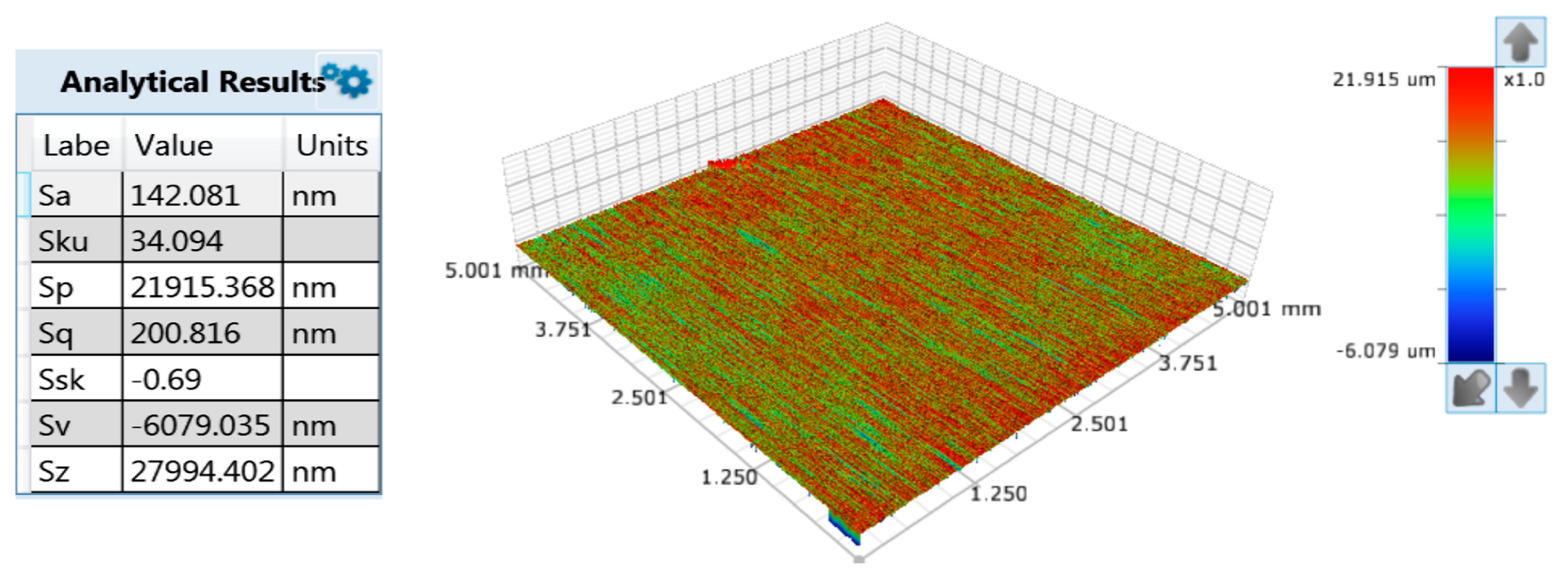
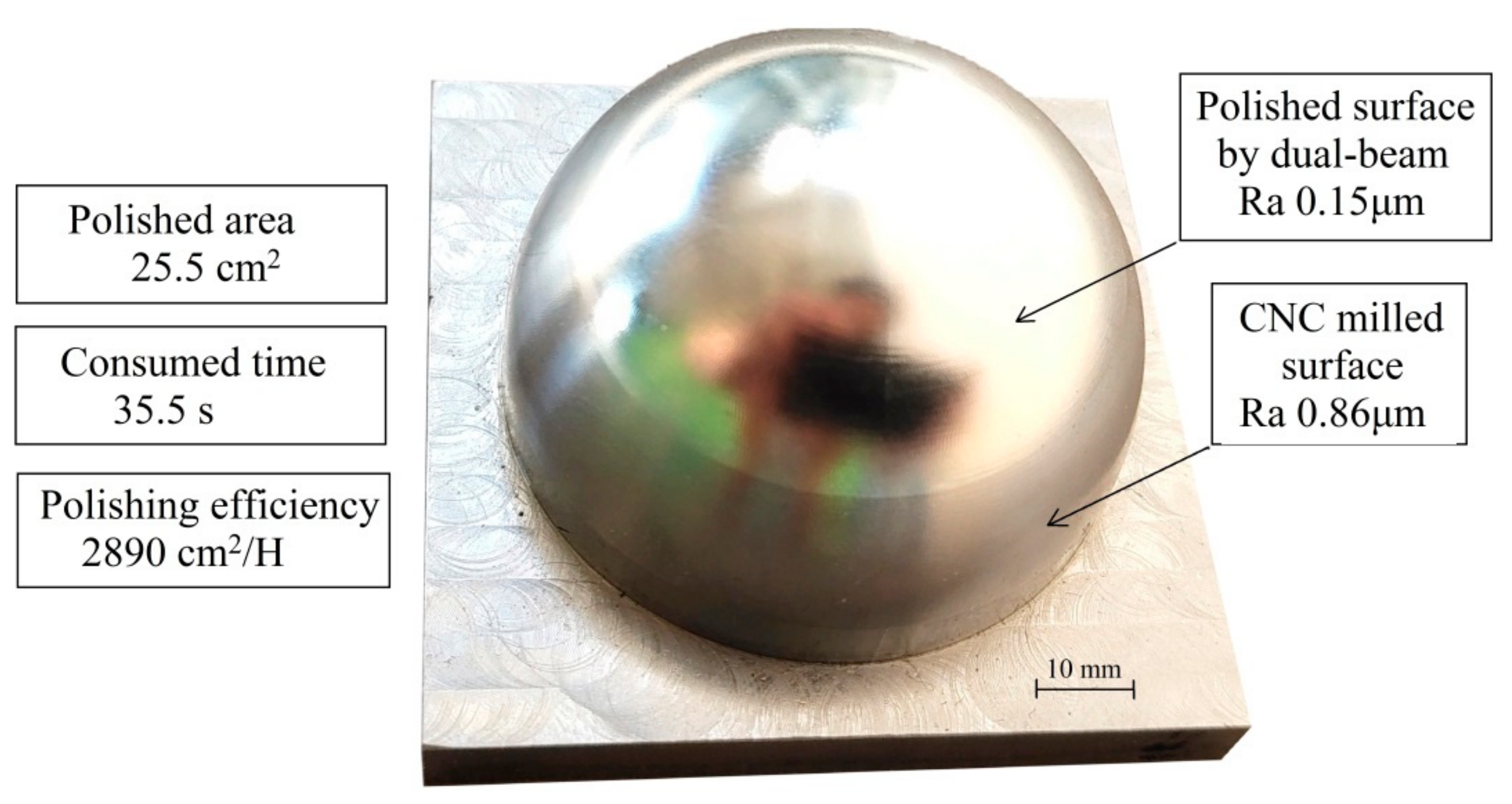
4. Results and Discussion

The experiment was taken according to the processes parameters given in Table 3. The white light interferometer (BRUKER WYKO Contour GT-K) was used again to measure the roughness of polished semisphere after polishing. Figure 11 is the measurement result, in which the sphere feature was removed to fit the true surface feature of roughness of Sa (=142 nm). Compared to Figure 5, the Sz value dropped much from 45931 to 27994 nm.
Figure 12 shows the actual polished semisphere associated with polishing performance data. The dual-beam took 35.5 s only to polish the semisphere surface resulted in the roughness reduction from initial state value of Sa (=877 nm) to post-polished value of Sa (=142 nm) as well as high laser polishing efficiency of 2890 cm2/H.
Numerous research have focused on the technology development of either CW laser polishing or pulsed laser polishing, very few studies have explored an approach to improve surface quality by the combination of CW laser polishing and pulsed laser polishing due to the large amount of the investment of such study and high uncertainty of experimental results.
The dual-beam laser polishing has the dual characteristics of both CW laser polishing and pulsed laser polishing, implementing the MPFV method effectively and leading to a decrease in peak-to-valley heights of the initial surface asperities. To achieve this, first of all, both individual laser processes are needed to be optimized, including setup of a series of appropriate parameters. In the experiment of CW laser polishing, the polishing parameters are given in Table 2, which had been optimized in previous works. A reverse beam extender and beam shaper was developed to make the spot irradiation of CW laser adjusted, ensuring that an appropriate spot diameter resulted in an optimized spot irradiation can be given under the condition that other parameters including top-hat beam profile of CW laser are fixed in advance.
The final surface quality achieved by PLμP relies on the performance of CW laser polishing. No matter how the PLμP is optimized, the final surface quality will not be improved if the surface roughness Sa achieved by CW laser polishing is more than 500 nm due to the evaporation of melted pool. To verify the importance of the optimization of CW laser polishing parameters, an experiment was conducted again using Table 2’s parameters. The scanning speed was changed from 800 to 100 mm/s, and other parameters remained unchanged. It was found that the CW laser polishing resulted in a large area of molten pool evaporation on the top of the semisphere as shown in Figure 13. Obviously, the result would become worse if the high irradiation were used or “poor” top-hat profile were applied.

5. Conclusions

The aim of this study was to explore an effective “melting peak for filling with valley” (MPFV) method to have dual-beam lasers polish steel freeform surface rapidly with smooth surface finish. The dual-beam consists of both a CW laser beam and a pulsed laser beam, whose profile patterns are top-hat. An initial rough surface was polished by a CW laser down to Sa (=426 nm) with high scanning speed 800 mm/s, meanwhile a pulsed laser plays a significant role to implement the MPFV method to polish the surface down to Sa (=142 nm), following up with the CW laser closely in the trajectory of zigzag-square wave. It took only around 35.5 s to polish a semisphere (ø60 mm) resulted in roughness reduction from initial state value of Sa (=877 nm) to post-polished value of Sa (=142 nm) of smoother surface finish. The dual-beam laser polishing efficiency is over 2890 cm2/H, more than 100 times that of manual polishing process. The main conclusion to be drawn from this study is that the trajectory of zigzag-square makes the pulsed laser which is following up with CW laser implement MPFV method more effectively and efficiently than conventional PLμP process. Future research will attempt to investigate further the pulsed laser mechanisms associated with the adjustment of spot diameters as well as to determine the optimized polishing parameters that will ensure the higher polishing efficiency with smoother surface finish.

Author Contributions

Conceptualization, Y.Z. and Z.Z.; Data curation, H.X. and X.X.; Formal analysis, Y.Z. and H.X.; Funding acquisition, W.Z. and X. X; Methodology, Y.Z.; Z.Z. and W.Z.; Project administration, Y.Z. and Z.Z.; Resources, W.Z.; Software, H.X.; Validation, W.Z.; Visualization, H.X. and X.X.; Writing–original draft, Y.Z.

Funding

This research was funded by Shenzhen Science and Technology Plan (No. GGFW2017041209483817, No. JCYJ20170817112440533 and No. JCYJ20170817114441260).

Acknowledgments

The authors acknowledge all experimental engineers for their contribution of laser polishing experiments. In particular, Huayi Gong and Pingjia Li and Gearay team.

Conflicts of Interest

The authors declare no conflict of interest. The funders had no role in the design of the study; in the collection, analyses, or interpretation of data; in the writing of the manuscript, or in the decision to publish the results.

References

  1. Burzic, B.; Hofele, M.; Mürdter, S.; Riegel, H. Laser polishing of ground aluminum surfaces with high energy continuous wave laser. J. Laser Appl. 2017, 29, 011701. [Google Scholar] [CrossRef] [Green Version]
  2. Perry, T.L.; Werschmoeller, D.; Duffie, N.A.; Li, X.; Pfefferkorn, F.E. Examination of selective pulsed laser micropolishing on microfabricated nickel samples using spatial frequency analysis. J. Manuf. Sci. Eng. 2009, 131, 021002. [Google Scholar] [CrossRef]
  3. Miller, J.D.; Tutunea-Fatan, O.R.; Bordatchev, E.V. Experimental analysis of laser and scanner control parameters during laser polishing of h13 steel. Procedia Manuf. 2017, 10, 720–729. [Google Scholar] [CrossRef]
  4. Athanasiou, C.-E.; Bellouard, Y. A monolithic micro-tensile tester for investigating silicon dioxide polymorph micromechanics, fabricated and operated using a femtosecond laser. Micromachines 2015, 6, 1365–1386. [Google Scholar] [CrossRef]
  5. Drs, J.; Kishi, T.; Bellouard, Y. Laser-assisted morphing of complex three dimensional objects. Opt. Express 2015, 23, 17355–17366. [Google Scholar] [CrossRef]
  6. Bordatchev, E.V.; Hafiz, A.M.; Tutunea-Fatan, O.R. Performance of laser polishing in finishing of metallic surfaces. Int. J. Adv. Manuf. Technol. 2014, 73, 35–52. [Google Scholar] [CrossRef] [Green Version]
  7. Goffin, N.; Tyrer, J.; Woolley, E. Complex beam profiles for laser annealing of thin-film cdte photovoltaics. J. Laser Appl. 2018, 30, 042006. [Google Scholar] [CrossRef]
  8. Hafiz, A.M.K.; Bordatchev, E.V.; Tutunea-Fatan, R.O. Influence of overlap between the laser beam tracks on surface quality in laser polishing of AISI H13 tool steel. J. Manuf. Process. 2012, 14, 425–434. [Google Scholar] [CrossRef]
  9. Bhaduri, D.; Penchev, P.; Batal, A.; Dimov, S.; Soo, S.L.; Sten, S.; Harrysson, U.; Zhang, Z.; Dong, H. Laser polishing of 3D printed mesoscale components. Appl. Surf. Sci. 2017, 405, 29–46. [Google Scholar] [CrossRef]
  10. Beam Shaper/Top-Hat. Available online: https://www.holoor.co.il (accessed on 9 May 2019).
  11. Kumstel, J.; Kirsch, B. Polishing titanium-and nickel-based alloys using cw-laser radiation. Phys. Procedia 2013, 41, 362–371. [Google Scholar] [CrossRef]
  12. Chang, C.-S.; Chen, T.-H.; Li, T.-C.; Lin, S.-L.; Liu, S.-H.; Lin, J.-F. Influence of laser beam fluence on surface quality, microstructure, mechanical properties, and tribological results for laser polishing of SKD61 tool steel. J. Mater. Process. Technol. 2016, 229, 22–35. [Google Scholar] [CrossRef]
  13. Vaithilingam, J.; Goodridge, R.D.; Hague, R.J.; Christie, S.D.; Edmondson, S. The effect of laser remelting on the surface chemistry of Ti6Al4v components fabricated by selective laser melting. J. Mater. Proc. Technol. 2016, 232, 1–8. [Google Scholar] [CrossRef]
  14. Richter, B.; Blanke, N.; Werner, C.; Vollertsen, F.; Pfefferkorn, F. Effect of initial surface features on laser polishing of Co-Cr-Mo alloy made by powder-bed fusion. JOM 2019, 71, 912–919. [Google Scholar] [CrossRef]
  15. Nüsser, C.; Sändker, H.; Willenborg, E. Pulsed laser micro polishing of metals using dual-beam technology. Phys. Procedia 2013, 41, 346–355. [Google Scholar] [CrossRef]
  16. Ukar, E.; Lamikiz, A.; Martínez, S.; Tabernero, I.; de Lacalle, L.L. Roughness prediction on laser polished surfaces. J. Mater. Process. Technol. 2012, 212, 1305–1313. [Google Scholar] [CrossRef]
  17. Pfefferkorn, F.E.; Duffie, N.A.; Morrow, J.D.; Wang, Q. Effect of beam diameter on pulsed laser polishing of S7 tool steel. CIRP Ann. 2014, 63, 237–240. [Google Scholar] [CrossRef]
  18. Liu, R.; Wang, Z.; Zhang, Y.; Sparks, T.; Liou, F. A smooth toolpath generation method for laser metal deposition. In Proceedings of the 27th Annual International Solid Freeform Fabrication Symposium, Austin, TX, USA, 8–10 August 2016; pp. 1038–1046. [Google Scholar]
  19. Roghanian, E.; Shakeri Kebria, Z. The combination of topsis method and Dijkstra’s algorithm in multi-attribute routing. Sci. Iran. 2017, 24, 2540–2549. [Google Scholar] [CrossRef]
  20. Rodríguez-Puente, R.; Lazo-Cortés, M.S. Algorithm for shortest path search in geographic information systems by using reduced graphs. SpringerPlus 2013, 2, 291. [Google Scholar] [CrossRef]
  21. Ahmadi, S.M.; Kebriaei, H.; Moradi, H. Constrained coverage path planning: Evolutionary and classical approaches. Robotica 2018, 36, 904–924. [Google Scholar] [CrossRef]
  22. Kapil, S.; Joshi, P.; Yagani, H.V.; Rana, D.; Kulkarni, P.M.; Kumar, R.; Karunakaran, K. Optimal space filling for additive manufacturing. Rapid Prototyp. J. 2016, 22, 660–675. [Google Scholar] [CrossRef]
  23. Selvaraj, P.; Radhakrishnan, P. Algorithm for pocket milling using zig-zag tool path. Def. Sci. J. 2006, 56, 117–127. [Google Scholar] [CrossRef]
Figure 1. Combination of CW laser expander and shaper.
Coatings 09 00324 g001
Figure 2. Quality of top-hat beam profile.
Coatings 09 00324 g002
Figure 3. Polished roughness related to initial roughness.
Coatings 09 00324 g003
Figure 4. Polished specimens.
Coatings 09 00324 g004
Figure 5. Dual-beam laser polishing system.
Coatings 09 00324 g005
Figure 6. Five-axis CNC device with dual-beam.
Coatings 09 00324 g006
Figure 7. Topography of polished surface by CW laser and measured data.
Coatings 09 00324 g007
Figure 8. Trajectory of two lasers: (a) zigzag of CW laser (b) square-wave of pulsed laser.
Coatings 09 00324 g008
Figure 9. Zigzag trajectory.
Coatings 09 00324 g009
Figure 10. Trajectory optimization. (a) vertices of the square wave; (b) trajectory of square wave.
Coatings 09 00324 g010
Figure 11. Measurement result of the semisphere.
Coatings 09 00324 g011
Figure 12. Polished semisphere by dual-beam.
Coatings 09 00324 g012
Figure 13. Vaporization occurred on the top of semisphere.
Coatings 09 00324 g013
Table 1. Group number corresponding to different spot irradiation.
Group #IIIIIIIV
Spot diameter Ds (mm)0.540.470.400.32
Spot Irradiation Ir. (kw/cm2)262346477746
Table 2. Optimized parameters of CW laser polishing in each group.
Factor NameOptimized Value or Feature
Roughness of initial state Sa (nm)7689831293186224433020361243614826
Scanning speed (mm/s)800800750750700700650650600
Top-hat beam profileBetween Medium and Ideal
Polishing parametersWavelength: 1080 nm, Power: 600 W, Step-over: 0.1 mm
Table 3. Parameters of the dual-beam laser polishing.
Set up Laser ParametersCW LaserPulsed Laser
Power600 W80 W
Wavelength1080 nm1064 nm
Beam profile pattern Top-hat (shaped)Top-hat
Pulse durationN/A1.3 μs
Spot diameter0.47 mm0.32 mm
Scanning speed800 mm/s2000 mm/s
Step-over0.1 mm0.1 mm
Scanning routeZigzagZigzag-square wave
Top-hat beam profileBetween Medium and Ideal

