Article

Pre-Coated Fe–Ni Film to Promote Low-Pressure Carburizing of 14Cr14Co13Mo4 Steel

1
State Key Laboratory of Advanced Welding and Joining, Harbin Institute of Technology, Harbin 150001, China
2
College of Physics, Mudanjiang Normal University, Mudanjiang 157011, China
3
School of Mechanical Engineering, Tianjin University of Technology and Education, Tianjin 300222, China
4
AECC Harbin Bearing Co., Ltd., Harbin 150001, China
5
School of Mechanical Engineering and Automation, Beijing University of Aeronautics and Astronautics, Beijing 100083, China
6
School of Mechatronics Engineering, Harbin Institute of Technology, Harbin 150001, China
*
Author to whom correspondence should be addressed.
Coatings 2019, 9(5), 304; https://doi.org/10.3390/coatings9050304
Submission received: 5 April 2019 / Revised: 27 April 2019 / Accepted: 30 April 2019 / Published: 6 May 2019

Abstract

:
Case-hardening 14Cr14Co13Mo4 martensitic stainless steel needs to be carburized to improve surface performance. Low-pressure carburization has the benefit of having oxidation-free production and being ecofriendly. However, compared with the low-pressure carburization of the low-alloy steel, low-pressure carburization of the 14Cr14Co13Mo4 steel consumes more time and has a risk of network carbides. In order to promote carbon diffusion and avoid network carbide, Fe–Ni films with various thickness were electrodeposited on the 14Cr14Co13Mo4 steel prior to low-pressure carburization. The experimental results show that, under the same carburizing conditions, the surface carbon content decreases and the carburized layer increases with the increase of Fe–Ni film thickness. After the hardening heat treatment, the effective case depth (ECD) of the sample coated with 6.0 μm Fe–Ni film was increased by 29% compared to that of the uncoated sample. The morphology of carbides was a strip-shaped, discontinuous network distribution in the uncoated sample, while in the Fe–Ni coated samples, the carbides changed to a globular, uniformly dispersed distribution. The effect of Fe–Ni film on the low-pressure carburizing of steel is explained by the simulation of the carbon diffusion using DICTRA software. The Fe–Ni films reduce the steel surface carbon content in each boost stage of low-pressure carburizing and release carbon atoms in every diffusion stage. Through this adjustment mechanism, the steel surface carbon content can be reduced and carburized layer growth can be promoted.

1. Introduction

Aircraft engines represent one of the most sophisticated engineering technologies and have forward strict performance requirements for bearing materials due to an increase in the thrust to weight ratio and work temperature [1]. Case-hardened martensitic stainless steels such as Pyrowear 675 [2] and CSS-42L [3] have been developed for bearings and gears to satisfy current and future requirements. The case-hardened stainless steels could have high surface hardness, wear resistance, and moderate corrosion resistance of the carburized layer, coupled with high fracture toughness of the core by carburizing and heat treating.
Low-pressure carburizing (LPC) has been widely used in modern heat treatment industries. LPC has many advantages over conventional gaseous carburization, such as excellent repeatability, oxidation-free products, a wider carburizing temperature range, and so on [4,5]. LPC usually uses acetylene or propane as a carbon donor, and operates in an oxygen-free atmosphere, which can avoid the oxidation of steels [6]. LPC is operated in consecutive stages: the boost stage followed by the diffusion stage, repeated one after the other. In the boost stage, the carburizing gas is supplied to the steel surface, until surface saturation with carbon is reached. In the diffusion stage, the carburizing gas is exhausted and only the carbon diffusion takes place in the steel.
Steel composition and carburizing process parameters are two main aspects affecting carburization. The carburizing process parameters mainly include: temperature, kinds of carburizing gases, flow rate [7], number of pulse cycles, ratio of boost, and diffusion time of each pulse cycle [8]. Numerous articles have studied the LPC of low-alloy steel, with fruitful results [9,10,11,12,13]. However, little research about the LPC of high-alloy steel, especially stainless steel, has published [14,15,16].
The high alloy content makes the LPC of stainless steel quite different from the low-alloy steel. On the one hand, raising the alloy content will reduce the carbon diffusion coefficient in austenite [17]. On the other hand, plenty of carbides precipitate and accumulate on the steel surface, which in turn hinders the carburization process [18]. The carbon atoms’ diffusion velocity along grain boundaries is faster than in grain, and the carbide nucleation barriers at grain boundaries are lower than in grain, which leads to a strong tendency to form network carbides during the carburization of stainless steels [19]. High carbon content facilitates carbide precipitation [20]. Reducing the steel surface carbon content in the boost stage of LPC is the key to avoiding the network carbide and promoting the growth of the carburized layer. Although shortening the boost time and prolonging the diffusion time of each pulse cycle can decrease the steel surface carbon content, looking for other methods to adjust the LPC of stainless steel is of significant interest and practical application value.
Coating is one of the surface modification technologies that can change the surface chemical composition and properties of materials. Coatings on material surfaces can affect carburization. NiAl intermetallic-based alloy coatings [21], Al oxide films [22,23], and Ni–Al and Ni–Re/Ni–Al films [24] were deposited on different materials to alleviate the carburization. In this paper, Fe–Ni films with different thicknesses were electrodeposited on 14Cr14Co13Mo4 steel prior to LPC. The influence of Fe–Ni film on the LPC of 14Cr14Co13Mo4 steel was studied by experiments and simulations.

2. Material and Methods

2.1. Material

The 14Cr14Co13Mo4 steel used in the present research is in the annealed condition with the chemical composition (wt.%) 0.14 C, 13.96 Cr, 12.73 Co, 4.36 Mo, 1.8 Ni, 0.6 V, and 0.5 W, and balance Fe. Specimens of 12 × 12 × 12 mm3 were mechanically ground with SiC emery paper up to 1000 grit. Specimens of Φ 26 mm × 55 mm were machined from the steel bar for carbon content distribution analysis.

2.2. LPC Parameters and Heat Treatment Conditions

The samples coated Fe–Ni films with various thicknesses, and uncoated samples were carburized in an IPSEN industrial LPC furnace. The carburizing gas consisted of 50% C2H2 and 50% H2. The carburized temperature was set at 890 °C. The total gas flow rate was 33.33 NL/min under a pressure of 1100 Pa during the boost stage. The duration of boost stage and diffusion stage was set in the following loop cycles of one cycle of 2 min/12 min, 2/22, 2/32, and 2/47, and seven cycles of 2/62. At the end of carburization, the samples were quenched using high-pressure nitrogen gas at a pressure of 1.5 MPa.
Some samples were taken out from the vacuum chamber for observing the microstructure and measuring the carbon concentration distribution. The other samples were reheated to 1100 °C and held for 40 min followed by gas quenching, then cryogenically treated in liquid nitrogen for 1 h, and finally tempered twice at 550 °C, each for 1 h.

2.3. Testing and Analysis Methods

The hardness distribution of the samples after hardening heat treatment was inspected using a micro-Vickers hardness tester (Wilson Hardness, MA, USA). The hardness test was carried out with a load of 200 g and a holding time of 15 s, taking the average of three measurements at the same depth as the hardness value. The effective case depth (ECD) was determined as the distance from a surface where the hardness is higher than Hv 550. The microstructures and chemical composition of the carburized layer were observed by optical microscope (OM, ZEISS, Cambridge, UK) and scanning electron microscopy (SEM, ZEISS, Cambridge, UK) equipped with energy dispersive X-ray analyzer (EDS). The cylindrical specimens were turned by the lathe using a hard alloy turning tool. The lathe spindle speed was set to be 140 r/min, and the nitrogen gas was purged to prevent oxidation. The depth of cut was 0.1 mm for each turning. The chips of each layer were collected and analysed by the Leco-CS200 carbon and sulphur analyzer (LECO, St Joseph, MI, USA).

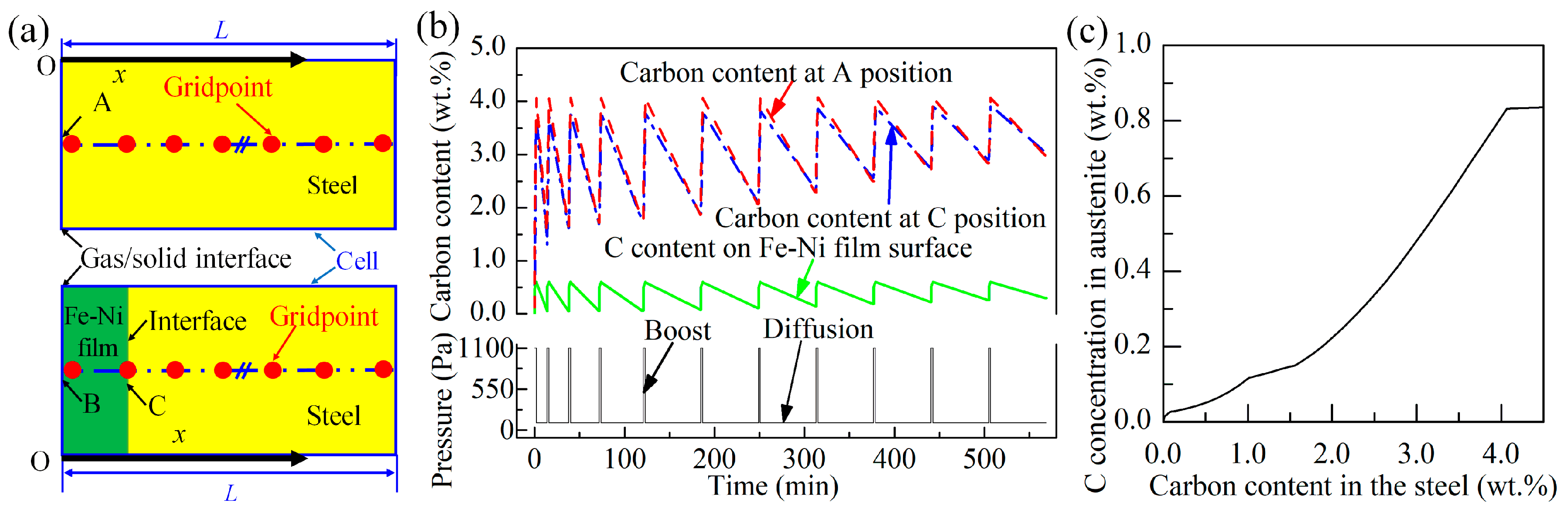
2.4. Experimental Design Principle

A method for calculating the carbon diffusion in the 14Cr14Co13Mo4 steel according to the LPC process has been build up in our previous paper [14], and is adopted in this paper to calculate carbon diffusion. Figure 1a shows the schematic of the calculation model. Detailed simulation method can be found in our previous article [14]. The red dashed line in Figure 1b shows the simulated carbon content on the 14Cr14Co13Mo4 steel surface as a function of carburization time. The carbon content rapidly reached about 4.08 wt.% in the boost stage of each cycle; then, the carbon content gradually decreased in the following diffusion stage. As the number of pulse cycles increases, the minimum carbon content increases from 1.54 wt.% to 2.98 wt.% at the end of each diffusion stage. Figure 1c shows the carbon concentration in austenite as a function of the carbon content in the steel at temperature of 890 °C calculated by Thermo-Calc software (Thermo-Calc version R). The carbon concentration in austenite is much smaller than that in the steel. The maximum carbon concentration in austenite is about 0.84 wt.%, and the remaining carbon exists in the carbides. In the carburizing process, carbon atoms diffuse in the austenite. A large amount of carbide precipitates on the steel surface, resulting in a austenite volume fraction decrease and hence decline in the carbon diffusion velocity. Therefore, we need to find a method to reduce the steel surface carbon content in the boost stage of LPC, hence reducing the amount of carbides.
Ni is an austenite stabilizing element, and the solid solubility of carbon in Ni is less than that in Fe. By depositing a Fe–Ni film on the steel, the carburization process becomes the carbon diffusion in the diffusion couple made up by the carburizing gases, the Fe–Ni film, and the steel. The schematic of the calculation model of diffusion couple is shown in the lower part of Figure 1a. The solid solubility of carbon in the Fe–Ni film can be adjusted by changing the Ni content, and changing the Fe–Ni film thickness can regulate the time of carbon atoms pass through the Fe–Ni film. In this paper, we only study the effect of Fe–Ni film thickness on LPC of 14Cr14Co13Mo4 steel. During the boost stage of each cycle, the Fe–Ni film surface carbon content reaches the solid solubility of 0.59 wt.%, and the carbon content gradually decreases during the subsequent diffusion stage. As the number of pulse cycles increases, the minimum carbon content increases from 0.05 to 0.30 wt.% at the end of each diffusion stage. The blue dotted line in Figure 1b shows the steel carbon content at the interface with the Fe–Ni film as a function of time. As the number of pulse cycles increases, the maximum carbon content increases from 3.66 to 3.92 wt.% at each boost stage. The results of the simulation calculations show that by coating a Fe–Ni film on the 14Cr14Co13Mo4 steel, the steel surface carbon content can be reduced during the boost stage. Therefore, Fe–Ni films with thicknesses of 1.4, 2.4, 3.8, and 6.0 μm were electrodeposited on the steel surface to adjust the carbon diffusion during the LPC process.

3. Results

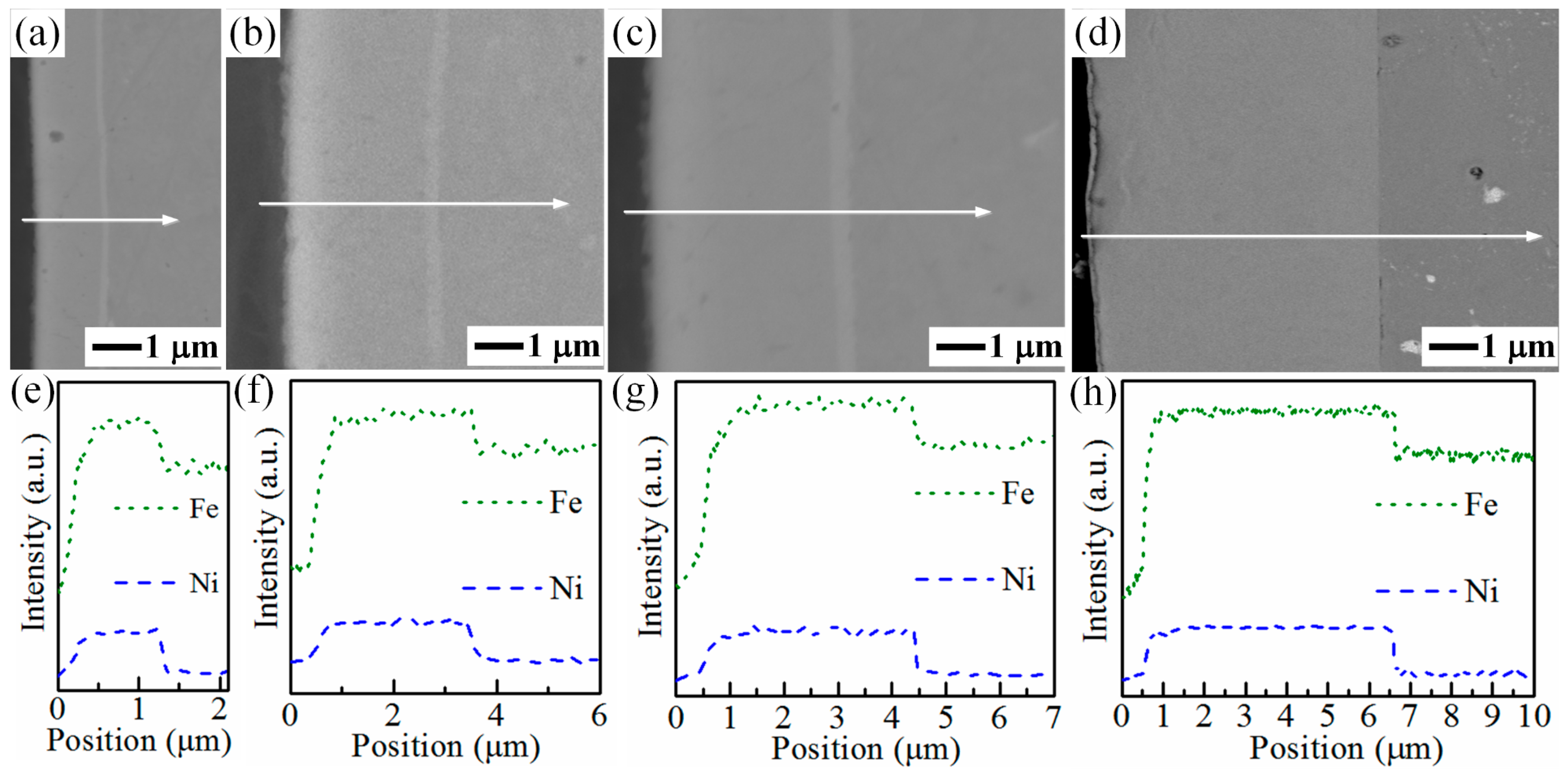
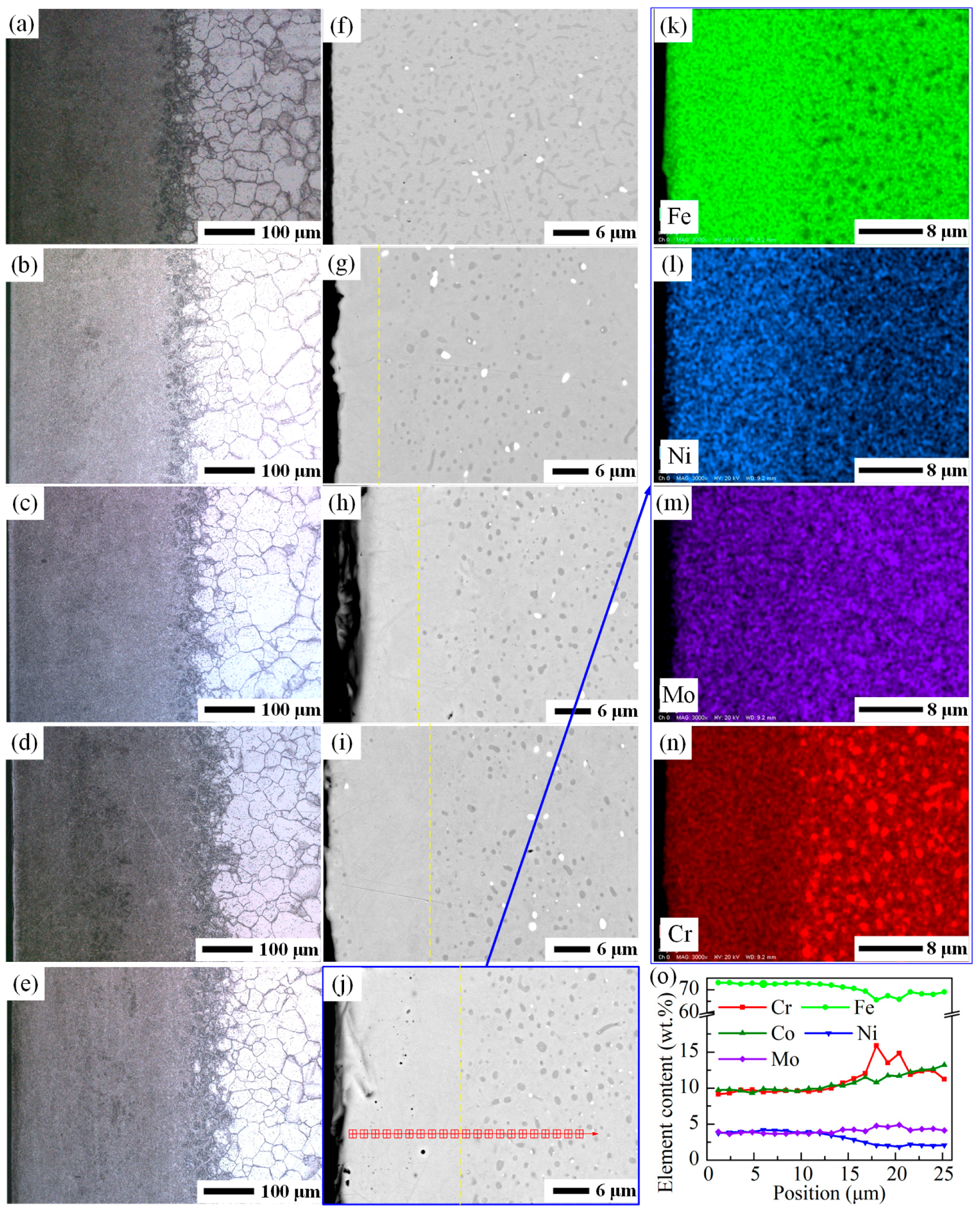
3.1. Characterization of the Fe–Ni Film

Figure 2 shows the SEM images of the cross-section of the samples coated with Fe–Ni films of various thicknesses, and corresponding EDS analysis results. The films are uniform for various thicknesses, and there are no holes in the films. The EDS line scan results indicate that there is no significant variation on Ni and Fe distribution across the thickness. EDS spot analysis results show that the film contains 81 wt.% Fe and 19 wt.% Ni.
The adhesion between the Fe–Ni film and the substrate is strong enough to keep the film from peeling off before and after LPC. When the Fe–Ni film thickness is not more than 3.8 μm, the bonding between the film and the substrate is good and no crack exists, as shown in Figure 2a–c. For the sample coated with 6.0 μm Fe–Ni film, as shown in Figure 2d, small cracks are observed on the interface between the film and the substrate. These cracks maybe caused by the grinding process of the metallographic sample preparation.

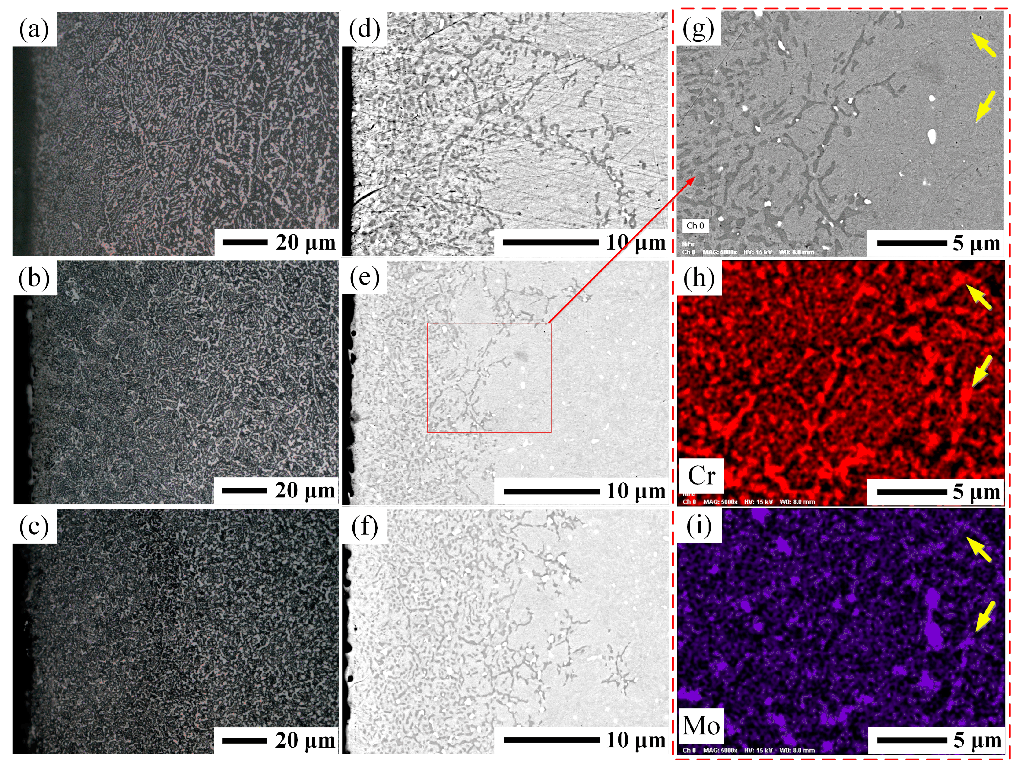
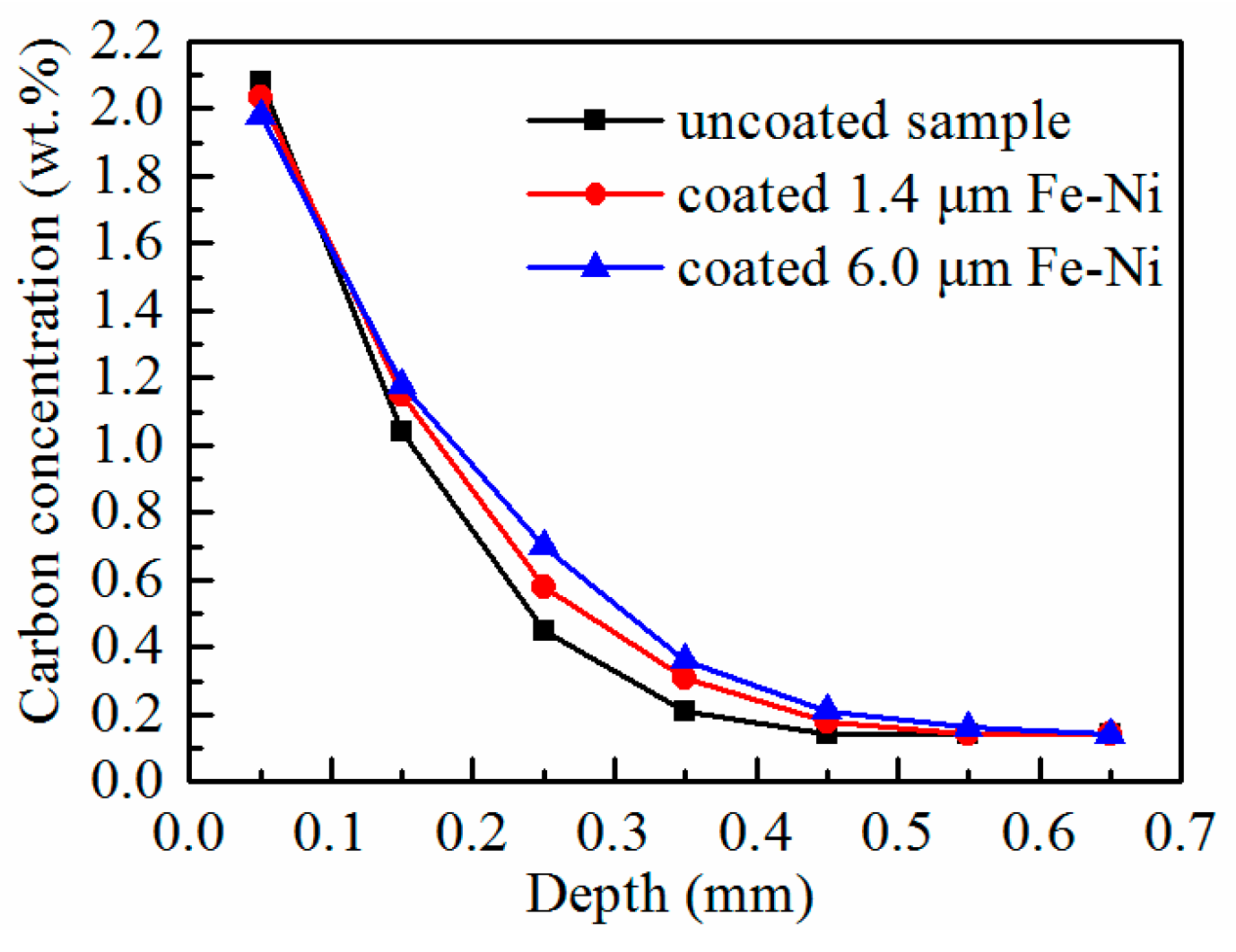
3.2. Characterization of the As-Carburized Layer

Figure 3a shows the cross-sectional metallographic picture of the as-carburized layer of the uncoated sample. A large amount of carbides precipitate in the as-carburized layer. The strip-shaped carbides are distributed along the grain boundaries and form network carbide. Spherical carbides are mainly distributed in the grains. Figure 3b,c show the cross-sectional metallographic pictures of the as-carburized layer of the samples coated 1.4 μm and 6.0 μm Fe–Ni films, respectively. Under the same carburizing conditions, the number of strip-shaped carbides in the samples coated with Fe–Ni film reduced compared to the uncoated sample. The carbide distribution was more uniform in the sample coated with 6.0 μm Fe–Ni film than that with 1.4 μm Fe–Ni film.
According to our previous research results [14], the 14Cr14Co13Mo4 steel carburized at 890 °C M7C3 precipitated mainly in the high-carbon content region, and M23C6 dominated in the low-carbon content region. The type of carbide can be directly distinguished by backscattered electron images. The dark gray carbide in backscattered electron images is M7C3, the light gray one is M23C6, and the white one is M6C. Figure 3d shows the cross-sectional backscattered electron image of the as-carburized layer of uncoated 14Cr14Co13Mo4 steel. Most of the M7C3 accumulates on the surface of the as-carburized layer, and a small amount of M7C3 extends inward along the grain boundaries. The uneven distribution of M7C3 indicates that the carburization is not uniform. As shown in Figure 3e,f, the M7C3 distribution in the as-carburized layer of Fe–Ni film-coated samples became more uniform than that of the uncoated one, and the depth of the M7C3 distribution was deeper in the steel coated with a 6.0 μm Fe–Ni film than the steel coated with a 1.4 μm Fe–Ni film. Since the samples were not etched, the contrast between M23C6 and steel matrix is low and difficult to distinguish the M23C6 in the backscattered electron images. However, through EDS mapping, M23C6 can be distinguished, and the arrows in Figure 3g–i point out the M23C6.
After carburizing at 890 °C for 569 min, alloying elements also diffuse in the diffusion couple between the Fe–Ni film and the steel. Figure 4 shows the backscattered electron image and element distribution of the sample coated with 6.0 μm Fe–Ni film. It can be seen in Figure 4a that the interface between the Fe–Ni film and the steel disappeared. The EDS element distribution results show that the Fe–Ni film is still rich in Fe and Ni, and some Cr atoms diffuse into the Fe–Ni film, as shown in Figure 4b–d. The simulation results of alloy element diffusion show that Ni diffuses inward by about 1.5 μm and Cr diffuses to the Fe–Ni film by about 3.6 μm, seen Figure 4e. The simulation results are basically consistent with the experimentally observed element distribution.
Figure 5 shows the carbon concentration profiles of the as-carburized samples. On the sample surface (thickness less than 0.1 mm), the uncoated sample had the highest carbon concentration of about 2.08 wt.%, followed by the sample coated with a 1.4 μm Fe–Ni film, and the sample coated with the 6.0 μm Fe–Ni film had the lowest carbon concentration. In other depths, the order was reversed. These indicate that under the same carburizing conditions, coating a Fe–Ni film on the steel can reduce the steel surface carbon concentration and promote the carbon diffusion into the core. By changing the Fe–Ni film thickness, the carbon concentration distribution can be changed.

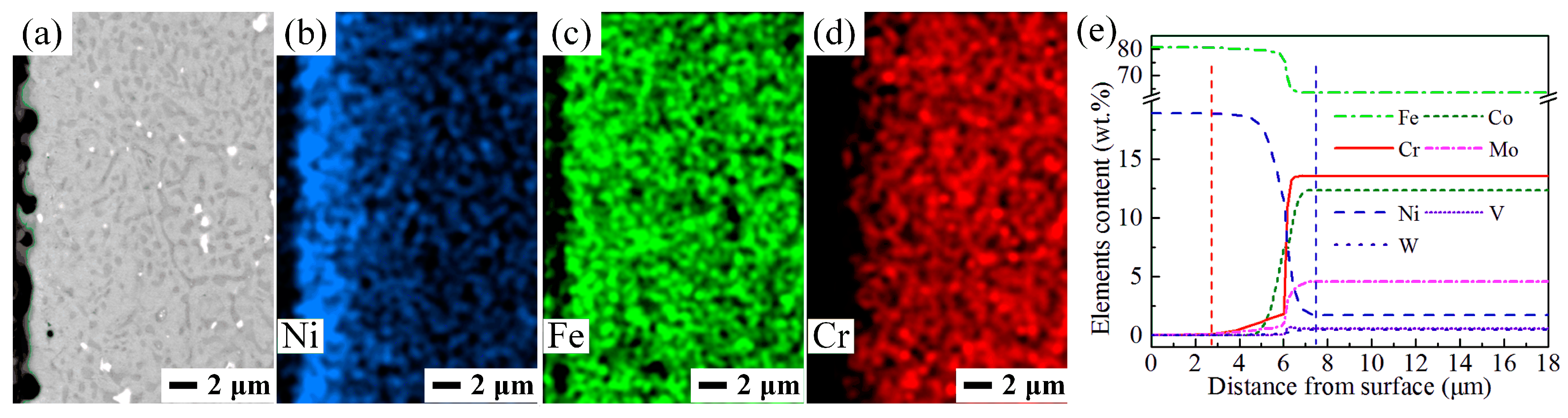
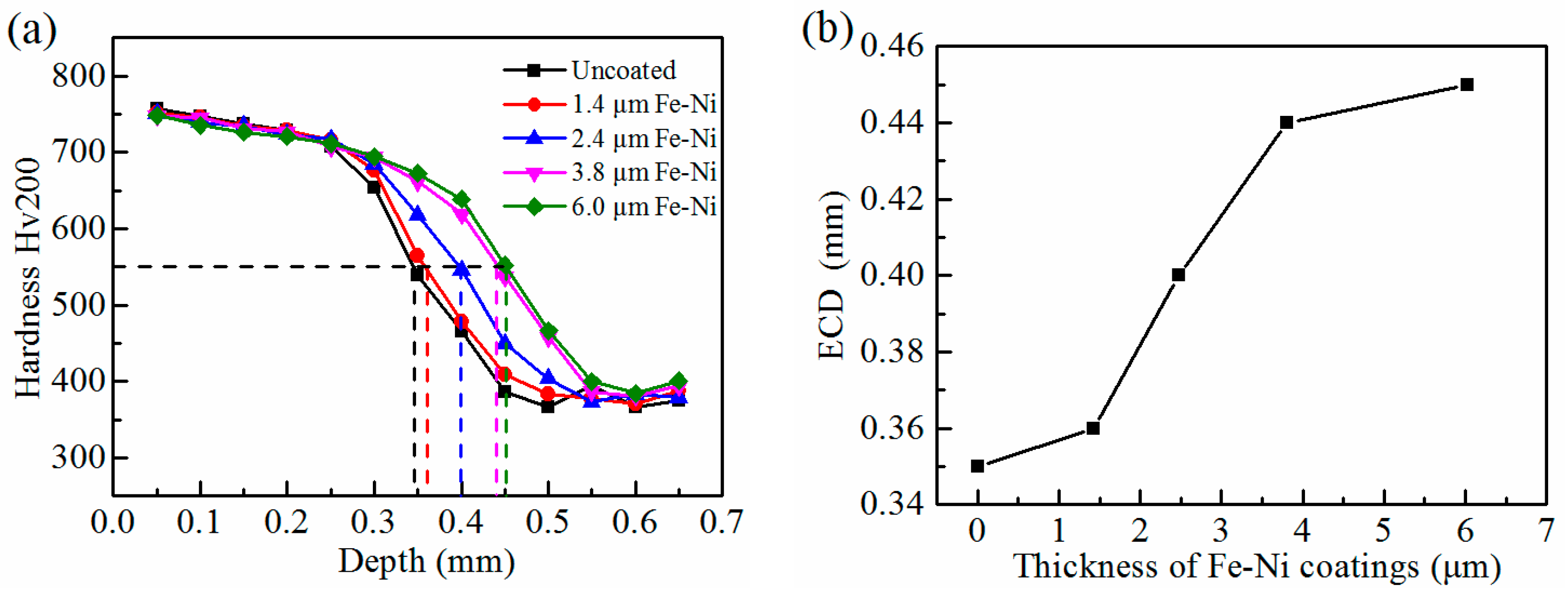
3.3. Characterization of the Carburized Layers after Hardening Treatment
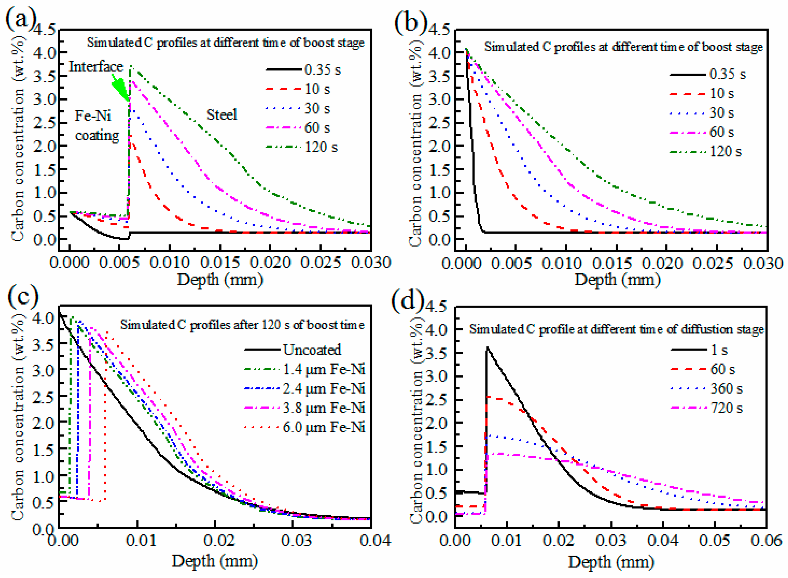
14Cr14Co13Mo4 steel displays a phenomenon known as secondary hardening [25]. In order to achieve an optimal combination of strength and toughness, carburized steel needs to be subjected to hardening heat treatment. During austenitization at 1100 °C for 40 min, the instable carbides dissolve, the remaining carbides spheroidize, and carbon atoms continue to diffuse inward. After being gas quenched, cryogenic treated, and double-tempered, the carburized layer consists of tempered martensite, retained austenite, undissolved carbides, and the carbides precipitated during the temper [16]. The metallograph and EDS results of the samples are shown in Figure 6.
As shown in Figure 6a–e, the depth of the carburized layer expands with the increasement of the Fe–Ni film thickness. Figure 6f shows the carbides appear as spherical and elongated strips in the uncoated sample. While in the samples coated with the Fe–Ni films, the carbides are mainly spherical and dispersed distributed, as shown in Figure 6g–j. Such differences are attributed to the different microstructures of the as-carburized layers, as shown in Figure 3. There is a carbide-free zone on the Fe–Ni film coated sample surface, and the carbide-free zone width increases as the Fe–Ni film thickness increases. The element distribution map of the sample coated with 6.0 μm Fe–Ni film, Figure 6k–n, shows that the carbide-free zone was enriched with Ni and Fe. Figure 6o shows that the chemical composition of carbide-free zone was 9.5 wt.% Cr, 9.7 wt.% Co, 3.9 wt.% Ni, 3.7 wt.% Mo, 0.3 wt.% V, and 72.7 wt.% Fe. Carbide stability depends on the chemical composition. High Fe and Ni content on the surface is the main reason for the formation of carbide-free zone. The diffusion behavior of the alloying elements during the austenitizing process is not the focus of this paper, so it will not be discussed further.
Figure 7a shows the hardness distribution of the samples after hardening heat treatment. The microhardness decreases from the surface to the core for all samples; the thicker the Fe–Ni film coated on the steel, the more slowly the hardness decreases. The difference in hardness gradient is caused by the different carbon concentration distribution. The effective case depth (ECD) is an important indicator for evaluating the carburized layer. The ECD values as a function of Fe–Ni film thickness are shown in Figure 7b. The ECD values increase rapidly for Fe–Ni film thicknesses less than 3.8 μm. When the the Fe–Ni film thickness further increased to 6.0 μm, the ECD value increased from 0.44 mm to 0.45 mm. The ECD of the sample coated with 6.0 μm Fe–Ni film increased 29% compared with that of the uncoated sample. This enhancement in ECD is due to the promoting effect of Fe–Ni film on LPC of 14Cr14Co13Mo4 steel.

4. Discussion

Carbon diffusion is determined by the steel composition and the carburizing process parameters. Acetylene has a strong carbon-donor capacity. In the boost stage, acetylene decomposes rapidly on the steel surface, and the activated carbon atoms enter the steel. The austenite saturated with carbon and carbide precipitate on the steel surface. In subsequent diffusion stage, the carbon atoms diffuse from the surface into the core, hence the decrease in surface carbon content. For LPC of low alloy steel, such as C20 steel carburized at 920 °C, by adjusting the LPC process parameters, the surface maximum carbon content reached about 1.3 wt.% in each boost stage and dropped to 0.9 wt.% at the end of each diffusion stage [13]. However, for carburizing 14Cr14Co13Mo4 steel, as shown in Figure 8a, the steel surface carbon content quickly reached a maximum value of about 4.08 wt.%. High-carbon content promotes carbide precipitation, and alloy carbides are relatively stable at carburizing temperature. In the diffusion stage, the carbides are hard to dissolve and release carbon atoms. Carbide affects carburization in two ways. On the one hand, the carbide accumulated on the steel surface will hinder the carbon atoms transfer from the carburizing gases into the steel. On the other hand, carbide precipitation reduces the austenite volume fraction. The austenite volume fraction decline reduces the carbon diffusion channel, causing the carbon diffusion coefficient decline. Therefore, reducing the carbon content decreases the amount of carbides that can promote the carbon diffusion.
Figure 8b shows the simulated carbon profiles of the steel coated with 6.0 μm Fe–Ni film at different boost time of the first carburizing cycle. Starting from the carburization, after about 0.35 s, carbon atoms pass through the Fe–Ni film to the interface of Fe–Ni film and steel. Thenceforth, carbon atoms cross the interface and diffuse into the steel. Due to the precipitation of carbides, the carbon content continuously increases on the interface of the steel side. The carbon content increases from 0.14 wt.% at 0.35 s to 2.43 wt.% at 10 s, to 2.83 wt.% at 30 s, to 3.47wt.% at 60 s, and to 3.66 wt.% at 120 s, respectively. The carbon content in the Fe–Ni film surface is always maintained at about 0.59 wt.%. Therefore, the Fe–Ni film can moderate the carbon atoms diffusion into the steel, and this moderating effect will weaken as the thickness of the Fe–Ni film decreases, as shown in Figure 8c. In the diffusion stage, as shown in Figure 8d, carbon atoms in the Fe–Ni film continue to diffuse into the steel driven by the chemical potential. In this process, the Fe–Ni film acts like a reservoir that releases carbon atoms. When the diffusion stage is completed, carburization proceeds to the next cycle. Therefore, by moderating the carbon atoms diffusion in the boost stage and releasing carbon atoms in the diffusion stage, Fe–Ni film can reduce steel surface carbon content and promote the growth of the case layer.

5. Conclusions

The pre-coated Fe–Ni film can be used as an effective approach to adjust LPC of the 14Cr14Co13Mo4 stainless steel. By depositing a Fe–Ni film on the steel, the carburization process becomes the carbon diffusion in the diffusion couple consisted by the carburizing atmosphere, the Fe–Ni film, and the steel. Under the same carburizing conditions, the carbide distribution is more uniform in the samples coated with Fe–Ni film. Fe–Ni film can enhance the as-carburized layer growth. After the hardening heat treatment, the ECD of the sample coated with 6.0 μm Fe–Ni film increases 29% compared to that of the uncoated sample. The carbide morphology changes from strip-shaped to spherical due to the influence of Fe–Ni film. The carbon diffusion simulation results demonstrate that the Fe–Ni film moderate the carbon atoms diffusion in the boost stage and release carbon atoms in the diffusion stage. By means of this regulation, the steel surface carbon content can be reduced and the carburized layer growth can be promoted.

Author Contributions

Conceptualization, L.Y.; Data curation, L.Y. and G.H.; Funding acquisition, X.M., T.W., L.W., and G.H.; Methodology, L.Y. and Z.F.; Software, L.Y. and L.L.; Supervision, X.M.; Writing–original draft preparation, L.Y.; Writing–review and editing, X.M., T.W. and L.W.

Funding

This research was funded by National Natural Science Foundation of China (No. 51705364, U1637206 and 51672120), Heilongjiang Province Applied Technology Research and Development Plan (No. GX16A004), and Natural Science Foundation of Tianjin (No. 18JCQNJC74900).

Conflicts of Interest

The authors declare no conflict of interest.

References

  1. Bhadeshia, H.K.D.H. Steels for bearings. Prog. Mater. Sci. 2012, 57, 268–435. [Google Scholar] [CrossRef]
  2. Trivedi, H.F.; Otto, F.; McCoy, B.; Bhattacharya, S.R.; Piazza, T. heat treatment process for martensitic stainless steel pyrowear 675 for improved corrosion resistance. In STP1580-EB Bearing Steel Technologies: 10th Volume, Advances in Steel Technologies for Rolling Bearings; Beswick, J., Ed.; ASTM International: West Conshohocken, PA, USA, 2015; pp. 465–484. [Google Scholar]
  3. Tomasello, C.M.; Burrrier, H.I.; Knepper, R.A.; Balliett, S.; Maloney, J.L. Progress in the evaluation of CSS-42LTM: A high performance bearing alloy. In STP1419-EB Bearing Steel Technology; Beswich, J.M., Ed.; ASTM International: West Conshohocken, PA, USA, 2002. [Google Scholar]
  4. Ryzhov, N.M.; Smirnov, A.E.; Fakhurtdinov, R.S.; Mulyakaev, L.M.; Gromov, V.I. Special features of vacuum carburizing of heat-resistant steel in acetylene. Metal Sci. Heat Treat. 2004, 46, 230–235. [Google Scholar] [CrossRef]
  5. Wolowiec-Korecka, E.; Korecki, M.; Klimek, L.; Kula, P.; Brewka, A.; Buczek, M. Low-pressure carburizing in a large-chamber device for high-performance and precision thermal treatment of parts of mechanical gear. Adv. Sci. Technol. Res. J. 2017, 11, 253–258. [Google Scholar] [CrossRef]
  6. Yada, K.; Watanabe, O. Reactive flow simulation of vacuum carburizing by acetylene gas. Comput. Fluids 2013, 79, 65–76. [Google Scholar] [CrossRef]
  7. Rokicki, P.; Dychton, K. Acetylene flow rate as a crucial parameter of vacuum carburizing process of modern tool steels. Arch. Metall. Mater. 2016, 61, 2009–2012. [Google Scholar] [CrossRef]
  8. Kula, P.; Pietrasik, R.; Dybowski, K. Vacuum carburizing-process optimization. J. Mater. Process. Technol. 2005, 164–165, 876–881. [Google Scholar] [CrossRef]
  9. Gorockiewicz, R.; Łapiński, A. Structure of the carbon layer deposited on the steel surface after low pressure carburizing. Vacuum 2010, 85, 429–433. [Google Scholar] [CrossRef]
  10. Wei, Y.; Zhang, L.; Sisson, R.D., Jr. Modeling of carbon concentration profile development during both atmosphere and low pressure carburizing processes. J. Mater. Eng. Perform. 2013, 22, 1886–1891. [Google Scholar] [CrossRef]
  11. Gronkiewicz, R. The kinetics of low-pressure carburizing of alloy steels. Vacuum 2011, 86, 448–451. [Google Scholar] [CrossRef]
  12. Kula, P.; Dybowski, K.; Wolowiec, E.; Pietrasik, R. “Boost-diffusion” vacuum carburizing—Process optimization. Vacuum 2014, 99, 175–179. [Google Scholar] [CrossRef]
  13. Zajusz, M.; Tkacz-Śmiech, K.; Danielewski, M. Modeling of vacuum pulse carburizing of steel. Surf. Coat. Technol. 2014, 258, 646–651. [Google Scholar] [CrossRef]
  14. Yin, L.; Ma, X.; Tang, G.; Fu, Z.; Yang, S.; Wang, T.; Wang, L.; Li, L. Characterization of carburized 14Cr14Co13Mo4 stainless steel by low pressure carburizing. Surf. Coat. Technol. 2019, 358, 654–660. [Google Scholar] [CrossRef]
  15. Turpin, T.; Dulcy, J.; Gantois, M. Carbon diffusion and phase transformations during gas carburizing of high-alloyed stainless steels: Experimental study and theoretical modeling. Metall. Mater. Trans. A 2005, 36, 2751–2760. [Google Scholar] [CrossRef]
  16. Hetzner, D.W.; Van Geertruyden, W. Crystallography and metallography of carbides in high alloy steels. Mater. Charact. 2008, 59, 825–841. [Google Scholar] [CrossRef]
  17. Rowan, O.K.; Sisson, R.D., Jr. Effect of alloy composition on carburizing performance of steel. J. Phase Equilib. Diffus. 2009, 30, 235–241. [Google Scholar] [CrossRef]
  18. Peng, Y.; Zhang, M.; Xiao, J.; Dong, J.; Du, C. Investigations on carburizing mechanisms of Cr35Ni45Nb subjected to different service conditions in a high-temperature vacuum environment. J. Mater. Res. 2015, 30, 841–851. [Google Scholar] [CrossRef]
  19. Trillo, E.A.; Murr, L.E. A TEM investigation of M23C6 carbide precipitation behaviour on varying grain boundary misorientations in 304 stainless steels. J. Mater. Sci. 1998, 33, 1263–1271. [Google Scholar] [CrossRef]
  20. Kaya, A.A. Microstructure of HK40 alloy after high-temperature service in oxidizing/carburizing environment: II. Carburization and carbide transformations. Mater. Charact. 2002, 49, 23–34. [Google Scholar] [CrossRef]
  21. Wang, Y.; Chen, W. Microstructures, properties and high-temperature carburization resistances of HVOF thermal sprayed NiAl intermetallic-based alloy coatings. Surf. Coat. Technol. 2004, 183, 18–28. [Google Scholar] [CrossRef]
  22. Uribe, E.; Salas, O.; Melo-Máximo, D.V.; Hernández-Durán, P.E.; Oseguera, J.; Torres, R.D. Evolution of PVD Al oxide coatings in carburizing atmospheres at high temperature. Surf. Coat. Technol. 2015, 284, 2–8. [Google Scholar] [CrossRef]
  23. Melo-Máximo, D.V.; Murillo, A.E.; Salas, O.; Melo-Máximo, L.; Oseguera, J. Behavior of uncoated and coated pure Fe in metal dusting conditions. Surf. Coat. Technol. 2016, 308, 10–18. [Google Scholar] [CrossRef]
  24. Li, M.; Li, N.; Zhang, J.; Zhou, C. Inhibiting effect of Ni–Re interlayer between Ni–Al coating and steel substrate on interdiffusion and carburization. Surf. Coat. Technol. 2018, 337, 68–74. [Google Scholar] [CrossRef]
  25. Crafts, W.; Lamont, J.L. Secondary hardening of tempered martensitic alloy steel. Trans. AIME 1949, 180, 471. [Google Scholar]
Figure 1. (a) Geometrical models showing the unit cell implemented for the low-pressure carborizing (LPC) simulation, the upper model for uncoated sample, and the lower model for Fe–Ni coated sample; (b) simulated C content as a function of LPC time at different positions marked on (a); and (c) carbon concentration in austenite as a function of total carbon content in the 14Cr14Co13Mo4 steel at 890 °C calculated by Thermo-calc software.
Coatings 09 00304 g001
Figure 2. Scanning electron microscopy (SEM) images of cross-section of the samples coated with Fe–Ni films of various thickness: (a) 1.4 μm, (b) 2.4 μm, (c) 3.8 μm, and (d) 6.0 μm; corresponding energy dispersive X-ray analyzer (EDS) line scan results at locations marked on SEM images: (e) 1.4 μm, (f) 2.4 μm, (g) 3.8 μm, and (h) 6.0 μm.
Coatings 09 00304 g002
Figure 3. The cross-sectional metallographic pictures of the as-carburized layers: (a) uncoated sample, (b) sample coated 1.4 μm Fe–Ni film, and (c) sample coated 6.0 μm Fe–Ni film; the cross-sectional backscattered electron images of the as-carburized layers: (d) uncoated sample, (e) sample coated 1.4 μm Fe–Ni film, (f) sample coated 6.0 μm Fe–Ni film, and (g) magnified image of the marked area in (e); EDS elements map: (h) Cr and (i) Mo. The arrows indicate the M23C6 carbides, which are low-contrast in the backscatter electron image in unetched condition.
Coatings 09 00304 g003
Figure 4. (a) Backscattered electron image of the sample coated with 6.0 μm Fe–Ni film; EDS elements map: (b) Ni, (c) Fe, and (d) Cr; (e) simulated alloy element profile after carburizing at 890 °C for 569 min.
Coatings 09 00304 g004
Figure 5. Carbon concentration profiles of the as-carburized samples.
Coatings 09 00304 g005
Figure 6. Metallograph of the samples: (a) uncoated sample, (b) coated 1.4 μm Fe–Ni film, (c) coated 2.4 μm Fe–Ni film, (d) coated 3.8 μm Fe–Ni film, and (e) coated 6.0 μm Fe–Ni film; backscattered electron images of the samples: (f) uncoated sample, (g) coated 1.4 μm Fe–Ni film, (h) coated 2.4 μm Fe–Ni film, (i) coated 3.8 μm Fe–Ni film, and (j) coated 6.0 μm Fe–Ni film; EDS elements map: (k) Fe, (l) Ni, (m) Mo, and (n) Cr; (o) chemical composition at different locations marked in (j) measured by EDS. The red dashed line indicates the depth of the case layer, and the yellow dotted line indicates the width of the carbide-free zone.
Coatings 09 00304 g006
Figure 7. (a) Hardness distribution of the samples after hardening treatment; the ECD of the carburized layer is marked in the figure. (b) The ECD values as a function of Fe–Ni film thickness.
Coatings 09 00304 g007
Figure 8. Simulated carbon profiles at temperature of 890 °C: (a) uncoated sample at different times during the boost stage, (b) sample coated with 6.0 μm Fe–Ni film at different times during the boost stage, (c) carbon profiles at the end of first boost stage, and (d) sample coated with 6.0 μm Fe–Ni film at different times during the diffusion stage.
Coatings 09 00304 g008

