Contribution of High Mechanical Fatigue to Gas Turbine Blade Lifetime during Steady-State Operation


Abstract
:1. Introduction
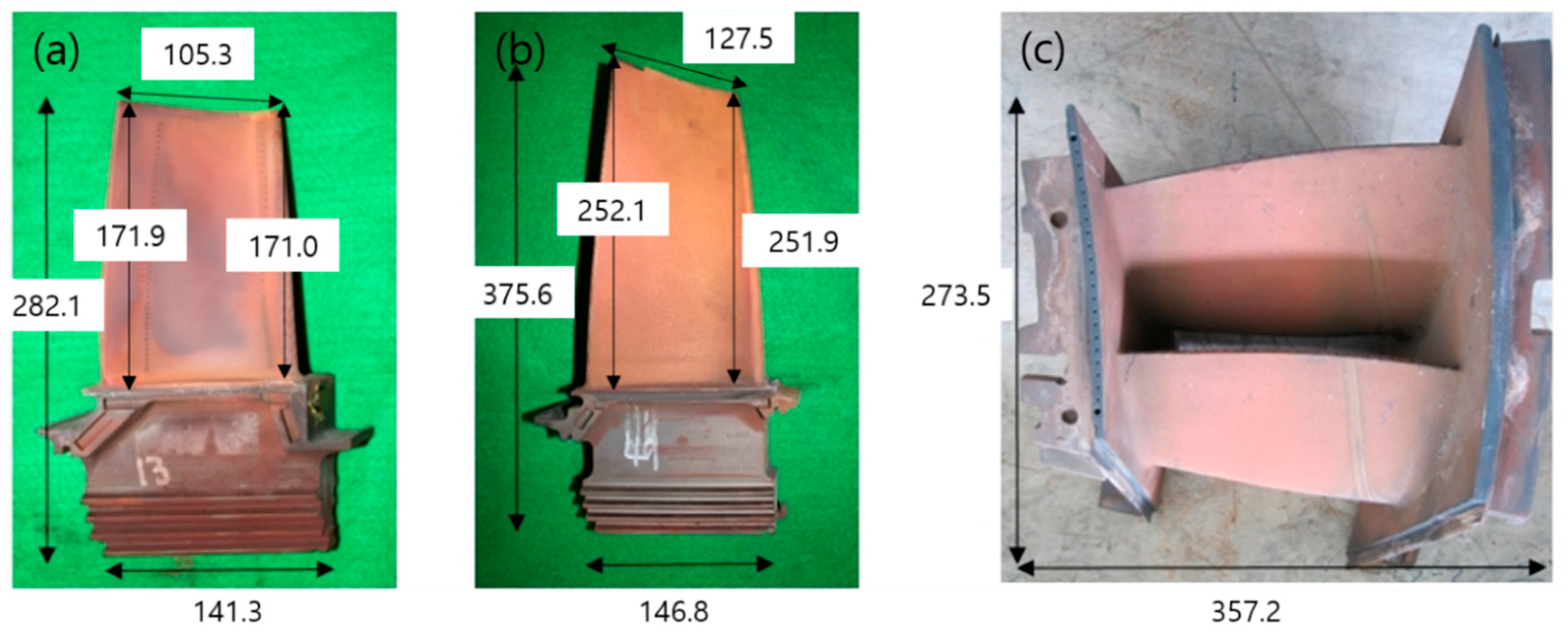
2. Experiments
3. Results and Discussion
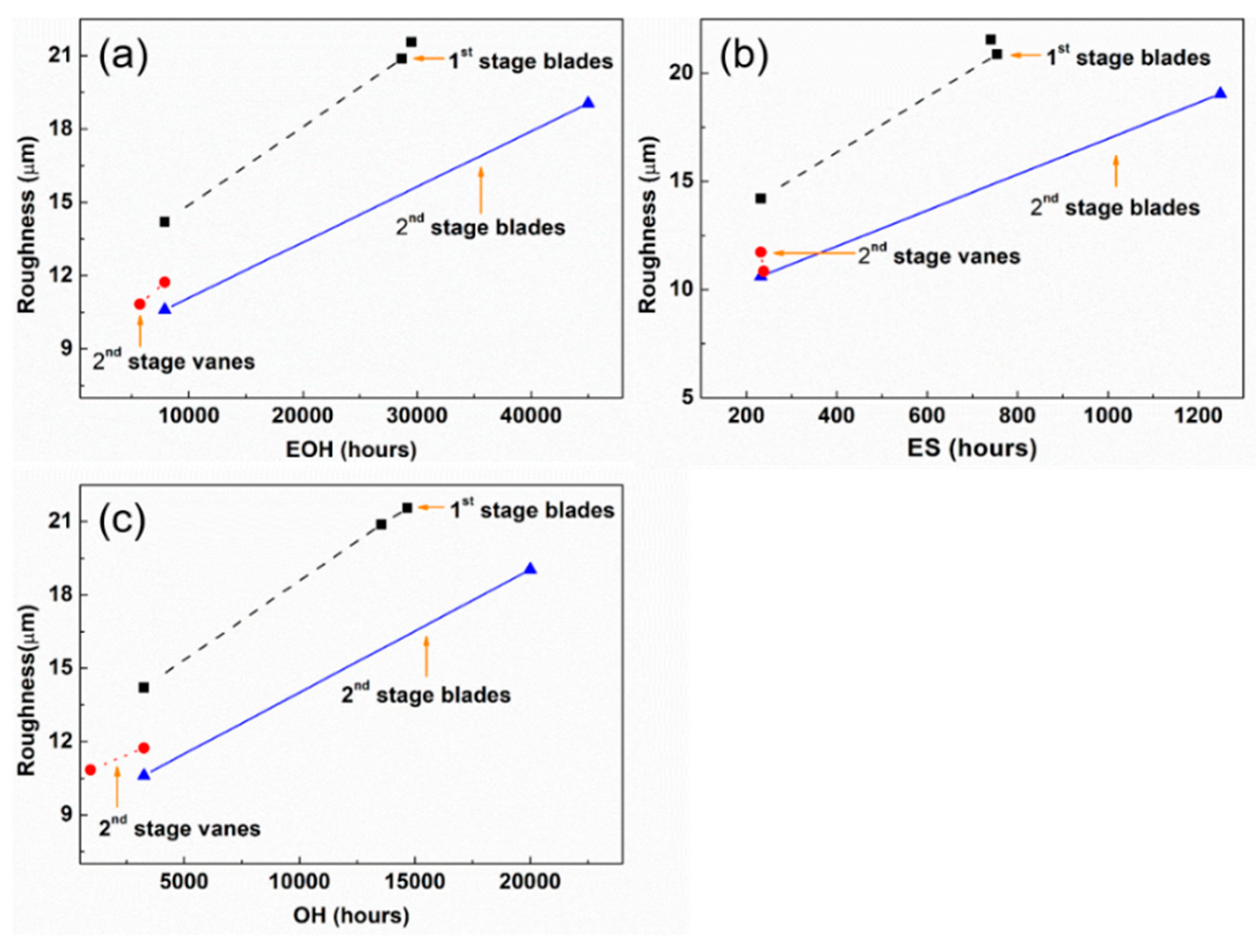
3.1. Contribution of Isothermal Heat Exposure to Fatigue
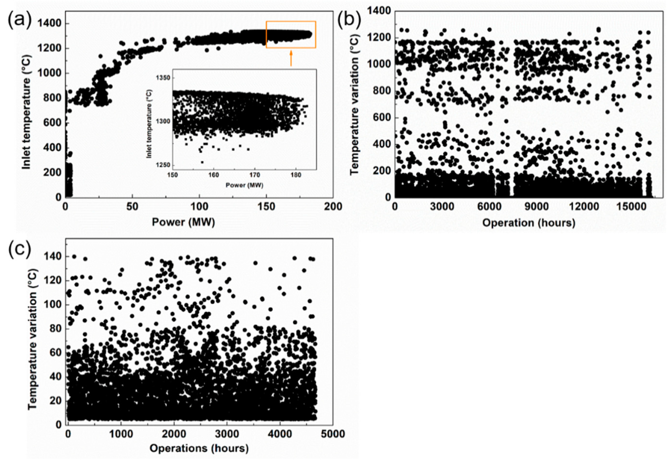
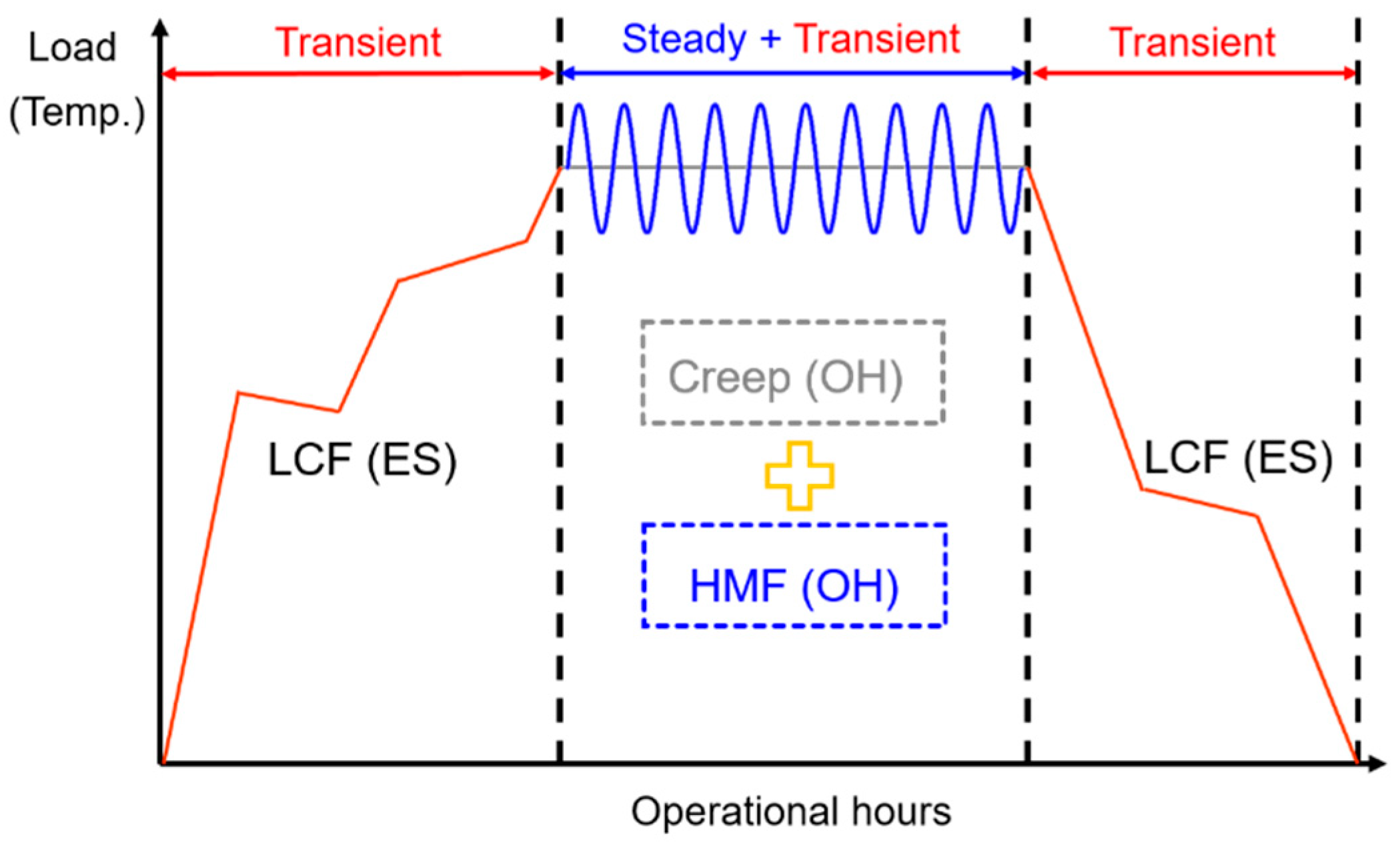
3.2. Effects of Steady-State and Transient Operations on Fatigue
4. Conclusions
- The low-cycle fatigue during a transient operation correlated highly with the lifetime of HGPCs and linearly depended on transient operation. Hence, the current method that accounts for transient operation to evaluate the RUL of a gas turbine is reasonable.
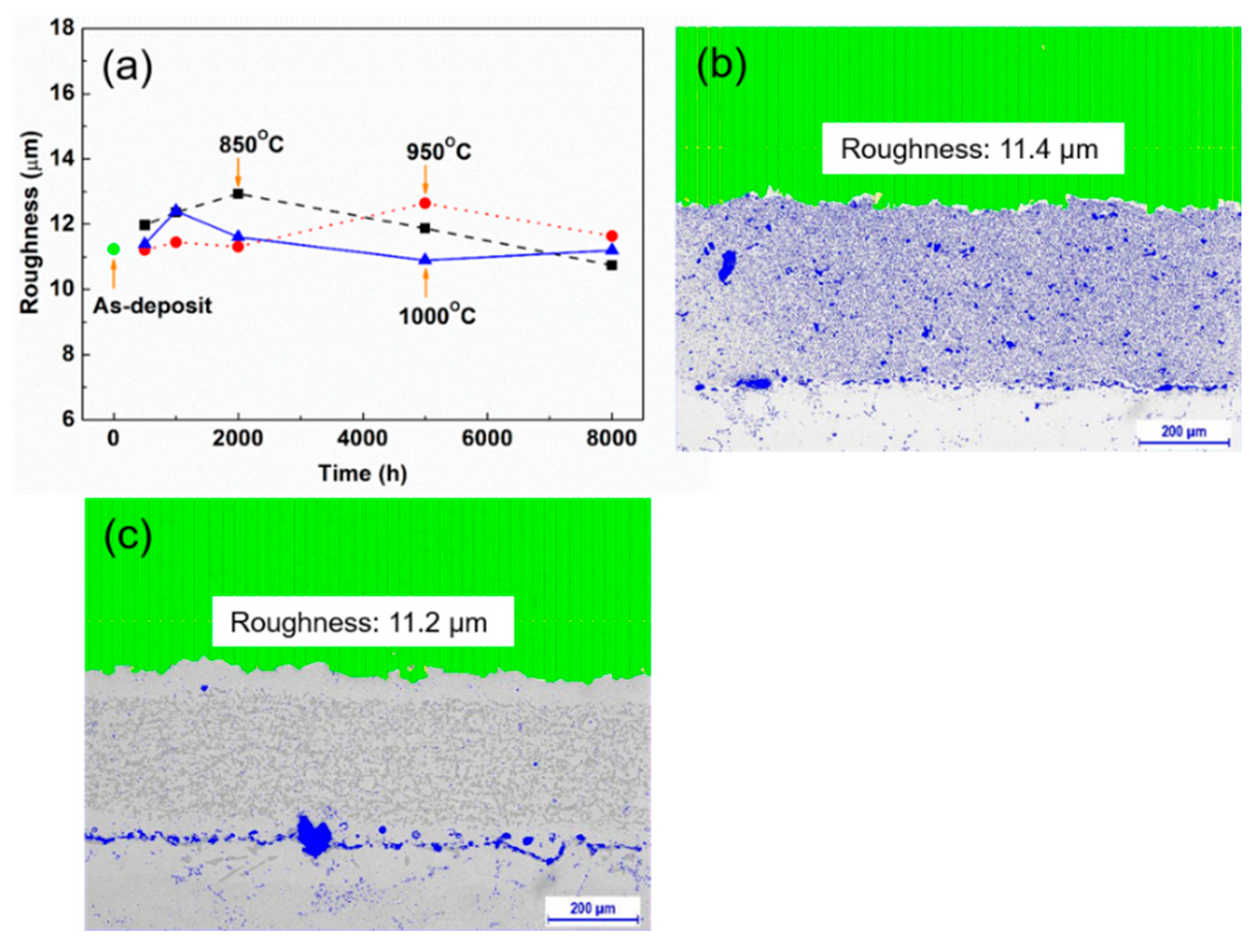
- Isothermal heat exposure during a steady state operation slightly contributes to the RUL of HGPCs. Laboratory experiments with coupon specimens show that isothermal heat exposure does not increase roughness, although it contributes to the evolution of creep. Hence, the current method that accounts for creep during steady state to evaluate the RUL of a gas turbine should be modified.
- The high thermomechanical fatigue during a steady state operation significantly contributes to fatigue and results in coating failure as the temperature fluctuates up to 140 °C during a steady state operation, whereas the current method to evaluate the RUL of a gas turbine assumes that there is no temperature fluctuation during a steady state operation.
- The current method to evaluate the RUL of a gas turbine accounts for the high thermomechanical fatigue instead of the creep during a steady-state operation. In the future, the study should focus on calculating the thermal stress and strain during the transient state and steady state and on evaluating the quantitative effect of HMF on coating degradation using additional long-term operational data at various operating conditions and results from laboratory experiments. A detailed phenomenological model of RUL that accounts for the effects of HMF will be developed and validated based on a quantitative analysis.
Author Contributions
Funding
Conflicts of Interest
References
- Sivakumar, R.; Mordike, B.L. High temperature coatings for gas turbine blades: A review. Surf. Coat. Technol. 1989, 37, 139–160. [Google Scholar] [CrossRef]
- Heppenstall, T. Advanced gas turbine cycles for power generation: A critical review. Appl. Therm. Eng. 1998, 18, 837–846. [Google Scholar] [CrossRef]
- Horlock, J.H. Advanced Gas Turbine Cycles: A Brief Review of Power Generation Thermodynamics; Elsevier: Amsterdam, The Netherlands, 2013. [Google Scholar]
- Ghai, R.C.; Chen, K.; Baddour, N. Modelling thermal conductivity of porous thermal barrier coatings. Coatings 2019, 9, 101. [Google Scholar] [CrossRef]
- Ye, D.; Wang, W.; Huang, J.; Lu, X.; Zhou, H. Nondestructive interface morphology characterization of thermal barrier coatings using terahertz time-domain spectroscopy. Coatings 2019, 9, 89. [Google Scholar] [CrossRef]
- Guo, X.; Zhao, W.; Zeng, Y.; Lin, C.; Zhang, J. Effects of splat interfaces, monoclinic phase and grain boundaries on the thermal conductivity of plasma sprayed yttria-stabilized zirconia coatings. Coatings 2019, 9, 26. [Google Scholar] [CrossRef]
- Lin, C.; Chai, Y.; Li, Y. Oxidation simulation of thermal barrier coatings with actual microstructures considering strength difference property and creep-plastic behavior. Coatings 2018, 8, 338. [Google Scholar] [CrossRef]
- Manero, A.; Knipe, K.; Wischek, J.; Meid, C.; Okasinski, J.; Almer, J.; Karlsson, A.M.; Bartsch, M.; Raghavan, S. Capturing the competing influence of thermal and mechanical loads on the strain of turbine blade coatings via high energy X-rays. Coatings 2018, 8, 320. [Google Scholar] [CrossRef]
- Dong, H.; Han, Y.; Zhou, Y.; Li, X.; Yao, J.-T.; Li, Y. The temperature distribution in plasma-sprayed thermal-barrier coatings during crack propagation and coalescence. Coatings 2018, 8, 311. [Google Scholar] [CrossRef]
- Xiao, Y.; Ren, E.; Hu, M.; Liu, K. Effect of particle in-flight behavior on the microstructure and fracture toughness of YSZ TBCs prepared by plasma spraying. Coatings 2018, 8, 309. [Google Scholar] [CrossRef]
- Daleo, J.A.; Ellison, K.A.; Boone, D.H. Metallurgical considerations for life assessment and the safe refurbishment and re-qualification of gas turbine blades. J. Eng. Gas Turbines Power 2002, 124, 571–579. [Google Scholar] [CrossRef]
- Padture, N.P.; Gell, M.; Jordan, E.H. Thermal barrier coatings for gas-turbine engine applications. Science 2002, 296, 280–284. [Google Scholar] [CrossRef]
- Janawitz, J.; Masso, J.; Childs, C. Heavy-Duty Gas Turbine Operating and Maintenance Considerations; GER: Atlanta, GA, USA, 2015. [Google Scholar]
- F-Class Combustion Turbine Life Management: Siemens V94.3A (SGT5-4000F); EPRI: Palo Alto, CA, USA, 2009; p. 1018614.
- Design Evolution, Durability, and Reliability of Alstom Heavy-Duty Combustion Turbines: Pedigree Matrices; EPRI: Palo Alto, CA, USA, 2013; Volume 5, p. 3002001073.
- Design Evolution, Durability, and Reliability of Siemens Heavy-Duty Gas Turbines: Pedigree Matrices; EPRI: Palo Alto, CA, USA, 2014; Volume 4, p. 3002006064.
- Design Evolution, Durability and Reliability of Mitsubishi Hitachi Heavy-Duty Gas Turbines: Pedigree Matrices; EPRI: Palo Alto, CA, USA, 2014; Volume 7, p. 3002003863.
- Design Evolution, Durability and Reliability of General Electric Heavy-Duty Gas Turbines: Pedigree Matrices; EPRI: Palo Alto, CA, USA, 2014; Volume 3, p. 3002003665.
- Lvova, E.; Norsworth, D. Influence of service-induced microstructural changes on the aging kinetics of rejuvenated Ni-based superalloy gas turbine blades. J. Mater. Eng. Perform. 2001, 10, 299–313. [Google Scholar] [CrossRef]
- Lvova, E. A comparison of aging kinetics of new and rejuvenated conventionally cast GTD-111 gas turbine blades. Mater. Eng. Perform. 2007, 16, 254–264. [Google Scholar] [CrossRef]
- Tolpygo, V.K.; Clarke, D.R. Surface rumpling of A (Ni, Pt) Al bond coat induced by cyclic oxidation. Acta Mater. 2000, 48, 3283–3293. [Google Scholar] [CrossRef]
- Panat, R.; Zhang, S.; Hsia, K. Bond coat surface rumpling in thermal barrier coatings. Acta Mater. 2003, 51, 239–249. [Google Scholar] [CrossRef]
- He, M.Y.; Evans, A.G.; Hutchinson, J.W. The ratcheting of compressed thermally grown thin films on ductile substrates. Acta Mater. 2000, 48, 2593–2601. [Google Scholar] [CrossRef]
- Im, S.H.; Huang, R. Ratcheting-inducted wrinkling of an elastic film on a metal layer under cyclic temperatures. Acta Mater. 2004, 52, 3707–3719. [Google Scholar] [CrossRef]
- Anton, R.; Bkrkner, J.; Czech, N.; Stamm, W. Degradation of advanced MCrAIY coatings by oxidation and interdiffusion. Mater. Sci. Forum 2001, 369, 719–726. [Google Scholar] [CrossRef]
- Viswanathan, R.; Cheruvu, N.S.; Chan, K.S. Coatings for Advanced Large Frame Combustion Turbines for Power Generation. In Proceedings of the ASME Turbo Expo 2003, Atlanta, GA, USA, 16–19 June 2003. [Google Scholar]
- Kiruthika, P.; Makineni, S.K.; Srivastava, C.; Chattopadhyay, K.; Paul, A. Growth mechanism of the interdiffusion zone between platinum modified bond coats and single crystal superalloys. Acta Mater. 2016, 105, 438–448. [Google Scholar] [CrossRef]
- Carter, T.J. Common failures in gas turbine blades. Eng. Fail. Anal. 2005, 12, 237–247. [Google Scholar] [CrossRef]
- Mazur, Z.; Ramirez, A.L.; Islas, J.A.J.; Amezcua, A.C. Failure analysis of a gas turbine blade made of Inconel 738LC alloy. Eng. Fail. Anal. 2005, 12, 474–486. [Google Scholar] [CrossRef]
- Vardar, N.; Ekerim, A. Failure analysis of gas turbine blades in a thermal power plant. Eng. Fail. Anal. 2007, 14, 743–749. [Google Scholar] [CrossRef]
- Poursaeidi, E.; Aieneravaie, M.; Mohammadi, M.R. Failure analysis of a second stage blade in a gas turbine engine. Eng. Fail. Anal. 2008, 15, 1111–1129. [Google Scholar] [CrossRef]
- Chan, K.S.; Cheruvu, N.S.; Leverant, G.R. Predicting Coating Degradation Under Variable Peak Temperatures. In Proceedings of the ASME Gas Turbine & Aeroengine Congress & Exhibition, Indianapolis, IN, USA, 7–10 June 1999. [Google Scholar]
- Cheruvu, N.S.; Chan, K.S.; Viswanathan, R. Evaluation, degradation and life assessment of coatings for land-based combustion turbines. Energy Mater. 2006, 1, 33–47. [Google Scholar] [CrossRef]
- Chan, K.S.; Cheruvu, S. Field Validation of a TBC Life-Prediction Model for Land-Based Gas Turbines. In Proceedings of the ASME Turbo Expo 2010, Scotland, UK, 14–18 June 2010. [Google Scholar]
- Ellison, K.A.; Daleo, J.A.; Hussain, K. A New Method of Metal Temperature Estimation for Service-Run Blades and Vanes. In Proceedings of the 10th International Symposium on Superalloys 2000, Champion, IL, USA, 17 September 2000; pp. 759–768. [Google Scholar]
- Smith, J.; Scheibel, J.; Classes, D.; Paschke, S.; Elbel, S.; Fick, K.; Carlson, D. Thermal barrier coating validation testing for industrial gas turbine combustion hardware. J. Eng. Gas Turbines Power 2016, 138, 031508. [Google Scholar] [CrossRef]
- Combustion Turbine Repair Guidelines: Hot Section Coatings, Hot Section Coatings; EPRI: Palo Alto, CA, USA, 2010; Volume 7, p. 1022336.
- Kniat, J. Means for Calculating Turbine Inlet Temperature of a Gas Turbine Engine. U.S. Patent 4055997A, 1 November 1977. [Google Scholar]
- Life Management System for Advanced F Class Gas Turbines: Siemens-Westinghouse W501F; EPRI: Palo Alto, CA, USA, 2005; p. 1008319.


| Sample # | Type | Stage | Equivalent Stop (ES) (h) | Operating Hours (OH) (h) | Equivalent Operating Hours (EOH) (h) |
|---|---|---|---|---|---|
| 1 | Blade | 1st | 741 | 14,674 | 29,494 |
| 2 | Blade | 1st | 755 | 13,546 | 28,646 |
| 3 | Blade | 1st | 232 | 3,248 | 7,888 |
| 4 | Blade | 2nd | 1249 | 20,000 | 44,980 |
| 5 | Blade | 2nd | 232 | 3,248 | 7,888 |
| 6 | Vane | 2nd | 238 | 947 | 5,707 |
| 7 | Vane | 2nd | 232 | 3,248 | 7,888 |
| Sample # | Operating Hours (OH) (h) | Equivalent Stop (ES) (h) | Equivalent Operating Hours (EOH) (h) | Scrap Rate (%) |
|---|---|---|---|---|
| Blade 1 | 10,908 | 376 | 18,428 | 50 |
| Blade 2 | 9403 | 464 | 18,683 | 34 |
| Blade 3 | 11,395 | 497 | 21,335 | 67 |
| Blade 4 | 10,727 | 545 | 21,627 | 74 |
© 2019 by the authors. Licensee MDPI, Basel, Switzerland. This article is an open access article distributed under the terms and conditions of the Creative Commons Attribution (CC BY) license (http://creativecommons.org/licenses/by/4.0/).
Share and Cite
Chang, S.Y.; Oh, K.-Y. Contribution of High Mechanical Fatigue to Gas Turbine Blade Lifetime during Steady-State Operation. Coatings 2019, 9, 229. https://doi.org/10.3390/coatings9040229
Chang SY, Oh K-Y. Contribution of High Mechanical Fatigue to Gas Turbine Blade Lifetime during Steady-State Operation. Coatings. 2019; 9(4):229. https://doi.org/10.3390/coatings9040229
Chicago/Turabian StyleChang, Sung Yong, and Ki-Yong Oh. 2019. "Contribution of High Mechanical Fatigue to Gas Turbine Blade Lifetime during Steady-State Operation" Coatings 9, no. 4: 229. https://doi.org/10.3390/coatings9040229
APA StyleChang, S. Y., & Oh, K.-Y. (2019). Contribution of High Mechanical Fatigue to Gas Turbine Blade Lifetime during Steady-State Operation. Coatings, 9(4), 229. https://doi.org/10.3390/coatings9040229