Article

Glancing Angle Deposition of Zn-Doped Calcium Phosphate Coatings by RF Magnetron Sputtering

1
Institute of Strength Physics and Materials Science of SB RAS, 634055 Tomsk, Russia
2
Research School of High-Energy Physics, National Research Tomsk Polytechnic University, 634050 Tomsk, Russia
3
Physical Chemistry and Center for Nanointegration Duisburg-Essen (CeNIDE), University of Duisburg-Essen, 45117 Essen, Germany
4
Inorganic Chemistry and Center for Nanointegration Duisburg-Essen (CeNIDE), University of Duisburg-Essen, 45117 Essen, Germany
5
Istituto di Struttura della Materia, Consiglio Nazionale delle Ricerche (ISM-CNR), 00133 Roma, Italy
*
Author to whom correspondence should be addressed.
Coatings 2019, 9(4), 220; https://doi.org/10.3390/coatings9040220
Submission received: 4 March 2019 / Revised: 21 March 2019 / Accepted: 25 March 2019 / Published: 28 March 2019
(This article belongs to the Special Issue Ion-Substituted Calcium Phosphates Coatings)

Abstract

:
Zn-substituted hydroxyapatite with antibacterial effect was used in radiofrequency (RF) magnetron deposition of calcium phosphate coating onto Ti- and Si-inclined substrates. The development of surface nanopatterns for direct bacteria killing is a growing area of research. Here, we combined two approaches for possible synergetic antibacterial effect by manufacturing a patterned surface of Zn-doped calcium phosphate using glancing angle deposition (GLAD) technique. A significant change in the coating morphology was revealed with a substrate tilt angle of 80°. It was shown that an increase in the coating crystallinity for samples deposited at a tilt angle of 80° corresponds to the formation of crystallites in the bulk structure of the thin film. The variation in the coating thickness, uniformity, and influence of sputtered species energy on Si substrates was analyzed. Coatings deposited on tilted samples exhibit higher scratch resistance. The coating micro- and nano-roughness and overall morphology depended on the tilt angle and differently affected the rough Ti and smooth Si surfaces. GLAD of complex calcium phosphate material can lead to the growth of thin films with significantly changed morphological features and can be utilized to create self-organized nanostructures on various types of surfaces.

1. Introduction

The demand for implants that can efficiently conduct bone defect regeneration increases significantly with the aging population [1]. It is known that the bioinert metals that are used in implantology and orthopedics do not provide the desired bioactivity and osteoconductivity; therefore, the surface of such medical devices is usually modified with bioactive coatings [2]. Moreover, the demand for antibacterial or bactericidal surfaces and coatings has increased steadily in recent years. It has been noted that the modern approach to surface modification should take into account both coating functions: osteoconduction properties and antibacterial effect [3]. From that perspective, substituted hydroxyapatites (HAs) are one of the most promising materials in this area of research. It has been shown that the easiness of atomic doping or substitution in HA reveals its potential to be used in various clinical cases [4,5,6]. Most importantly, it has been shown that inorganic antibacterial metallic ions (e.g., Ag, Cu, Zn, Sr) can be introduced into the HA lattice and improve its antibacterial properties [7,8,9,10,11,12,13,14]. However, there is a physical approach to antibacterial surface production. It has been shown that the creation of nanopatterns is a powerful tool for directing stem cell fate. Another advantage is that high aspect ratio nanopatterns are capable of killing bacteria and preventing biofilm formation [15].
Modern approaches to healthcare are aiming to produce implants with biomimetic properties [16]. These properties are crucial to ensuring a desirable biological response to the newly implanted material, in such a manner that the cells, which are adhered to the surface of such scaffolds, can function in a way that is similar to physiological conditions. From that point of view, the formation of a coating that consists of different types of surface gradient structures and with variations in the level of roughness on the submicro- and nanoscale could be of significant interest for biomimetic purposes [17,18]. The possibility of manipulating nanotopography has attracted much attention in recent years [19,20,21,22]. This has fostered the development of film deposition techniques aimed at enhancing these morphological characteristics.
In the field of optics and microelectronics, physical vapor deposition (PVD) of thin films, allowing the deposition of porous and/or columnar-like structured coatings, has been available for some years. For this purpose, the use of an oblique angle geometrical configuration—or as it is also known, glancing angle deposition (GLAD) method—is frequently exploited [23,24,25,26,27].
The GLAD configuration has emerged as a promising tool for the deposition of nanostructured thin films. This method has mostly been applied in the field of metallic coatings or dielectric coatings for optical systems, and the use of such technology in the field of biomaterials started recently [28]. Such coatings are usually represented by inclined columnar-like structures with variations at the nano-roughness level and a direction of growth allowing for the deposition of patterned structures with different shapes and sizes. GLAD has a wide range of applications in various fields, such as sensors [29], optics [30,31], or solar cells [32]. This type of coatings has attracted attention due to the anisotropic nature of the formed films, their peculiar mechanical properties, and the possibility of controlling the level of porosity [33] and roughness [34]. Most researchers who have utilized the GLAD method have used line-of-sight methods of deposition, such as, for example, thermal evaporation. However, the effect of self-shadowing is applicable in many PVD techniques, such as magnetron sputtering.
An emerging method for bioactive coating deposition in the field of PVD is radiofrequency (RF) magnetron sputtering. Magnetron sputtering is widely used in the formation of coatings for various applications. The continuous interest of scientists in this method is due to the possibility of modifying the coating structure and its physicochemical properties by varying the deposition parameters [2]. There is a significant interest in radiofrequency (RF) magnetron sputtering of bioactive calcium phosphate (CaP) thin films [35,36]. This method allows for the deposition of CaP coatings with a high level of adhesion to the substrate. Moreover, RF magnetron sputtering is well known as a highly controllable deposition method. However, to date, a feasible method of calcium phosphate coating deposition in GLAD geometry via RF magnetron sputtering has not yet been reported.
Here, we aimed to develop a method for depositing thin Zn-substituted HA (Zn-HA)-based coatings that are formed by hierarchical gradient surface features with the use of GLAD geometry. This method allows us to manipulate the coating roughness on the submicron and nanoscale level and pursue the possible synergetic antibacterial effect of a nanopattern and the antibacterial activity of Zn.

2. Materials and Methods

Commercially pure titanium samples (99.58 Ti, 0.12 O, 0.18 Fe, 0.07 C, 0.04 N, and 0.01 H wt %) of 10 × 10 × 1 mm3 size provided by “VSPO-AVISMA” (Perm, Russia) were used as substrates. The samples were sequentially polished by silicon carbide paper of 120, 480, 600, and 1200 grit. Prior to deposition, the substrates were cleaned in an ultrasonic bath of distilled water for 10 min. Furthermore, commercially available Si wafers (1 0 0) provided by “ELMA” (Zelenograd, Russia) were used as substrates in all the deposition runs.
In Figure 1, the deposition process is schematically shown. The samples were mounted on the custom-made sample holder at different angles to the flux of the sputtered material.
The sample holder allows for the simultaneous placing of substrates at 0°, 60°, or 80° to ensure the same sputtering conditions for all the deposited samples.
The sputtering target was Zn-substituted hydroxyapatite. This material was chosen because hydroxyapatite resembles the mineral fraction of bone and is used for many implant coatings, while the addition of Zn can provide faster bone growth together with an antibacterial effect [37]. A Zn-HA powder was prepared by mechanochemical synthesis at the Institute of Chemistry and Mechanochemistry, Russian Academy of Sciences, Novosibirsk, Russia. The mechanochemical synthesis was carried out according to the reaction:
6 CaHPO 4 + ( 4 x ) CaO + x ZnO = Ca ( 10 x ) Zn x ( PO 4 ) 6 ( OH ) 2 + 2 H 2 O ,   where   x   =   0.4 .
The prepared powder was used as a precursor for the preparation of a target for sputtering. Its detailed characterization can be found in our previous report [38]. The powder was pressed and then sintered in air at 1100 °C for 1 h. The chemical composition of the powder and the target was confirmed by X-ray powder diffraction (XRD) and Fourier transform infrared spectroscopy (FTIR) [39].
To identify the optimal deposition parameters for our experiment, we reviewed the literature dealing with GLAD, considering the substrate material, sputtered material, deposition parameters, and type of formed coatings. In Table 1, the deposition parameters for GLAD of various materials and their properties are summarized.
Even though most GLADs were performed at target-to-substrate distances larger than 70 mm, we decided to perform deposition at a distance of 45 mm, as it is consistent with most published research papers dealing with sputtering of CaPs [47,48,49] and ensures that the particle-free mean path is significantly higher than the target-to-substrate distance. Moreover, it is known that ZnO and hydroxyapatite share the same type of lattice structure (hexagonal system). Taking into account the fact that there is a correlation between the lattice type of sputtered material and the type of the formed coating structure, we hypothesized that using similar deposition parameters to those used for ZnO would result in the formation of Zn-doped calcium phosphate nanocolumns [42,46,50].
A vacuum installation with a planar magnetron operating at a frequency of 13.56 MHz (TPU, Tomsk, Russia) was utilized for GLAD. The high-quality Zn-HA target was used as the cathode of the magnetron. The sputtering power density was set to 3.15 W/cm2. Prior to the deposition, the system was pumped to a base pressure of 5 × 10⁻⁶ Torr, and then, Ar gas was passed through at a controlled rate to maintain the pressure needed for the experimental deposition. The deposition time was set to 3 h, and the target-to-substrate distance was 45 mm. It is important to note that the target-to-substrate distance varied for tilted samples due to the inclination; therefore, the upper part of the sample was as close to the surface of the magnetron as 35 mm. The samples were deposited at a working gas pressure of 0.8 mTorr at a gas flow of 3.7 sccm. Each set of samples with angles varied from 0 to 80° was deposited in a single run.
The thicknesses of the deposited films were measured using spectroscopic ellipsometry with an ELLIPS-1891 SAG setup (Rzhanov Institute of Semiconductors Physics of SB RAS, Novosibirks, Russia). The surface morphology and composition of the coatings were examined with scanning electron microscopy using an ESEM Quanta 400 FEG scanning electron microscope (SEM, FEI Company, Hillsboro, OR, USA) operating in a high vacuum. The samples were coated with gold–palladium for 15 s before the SEM, which was equipped with energy-dispersive X-ray spectroscopy (EDX; Genesis 4000, SUTW-Si(Li)detector, EDAX, Inc., Mahwah, NJ, USA) and was operating in a high vacuum study in such a way that no alteration of the surface morphology was induced. The estimated thickness of the deposited Au–Pd layer was 4–5 nm. The acceleration voltage for the SEM was 20 kV. To determine the level of crystallinity of the studied samples and estimate the crystallite size of the deposited thin CaP coatings, a Panalytical Empyrean X-ray diffractometer with a Cu Kα radiation source (λ = 1.54 Å; 40 kV and 40 mA) was used. The coatings were investigated by grazing incidence X-ray diffraction (GIXRD) with an incident beam angle of Ψ = 1.0° (with respect to the sample surface) and at 2θ range from 5° to 90° with a step size of 0.05°. For qualitative phase analysis with the Bruker software Diffrac.Suite EVA 4.2.2, the patterns of hydroxyapatite (#09-0432) and titanium (#44-1294) from the ICDD database were used as a reference. After the instrumental correction derived from a standard powder sample LaB6 from the NIST ([51]; a(LaB6) = 4.15689 Å), quantitative Rietveld analysis for the calculation of the lattice parameters and the crystallite sizes was performed with the Bruker software TOPAS 5.0. For the morphology visualization and calculation of the surface roughness level of the samples, a JPK NanoWizard Atomic Force microscope (AFM, JPK, Berlin, Germany) was used. The coating-to-substrate adhesion evaluation was carried out with the scratch-test method on a CSM Macro Scratch Tester Revetest (CSM Instruments, Needham Heights, MA, USA) with an indenter of 20 μm in radius. The maximum indentation load was 10 N. The scratch length was set to 5 mm. In order to obtain statistically meaningful data, each measurement was repeated at least three times per sample.

3. Results and Discussion

3.1. Effect of GLAD on Coating Thickness and Its Uniformity along the Substrate Surface

The key for variation in the coating surface topography when the GLAD method is used lies in the self-shadowing effect [23]. During the film growth, adatoms migrate to the substrate and encounter the surface in a way that causes peak and valley regions to grow. Due to the inclination of the substrate, the peaks receive more atoms compared with the valleys. As the peaks grow higher, a shadow region, which receives a lower number of atoms, is formed behind them. Consequently, the GLAD coatings have a preferential direction of growth and may even be porous. Also, in most of the reports dealing with GLAD, an increase in root-mean-square (RMS) surface roughness is usually observed when compared with the normal degree deposition [25,26,29].
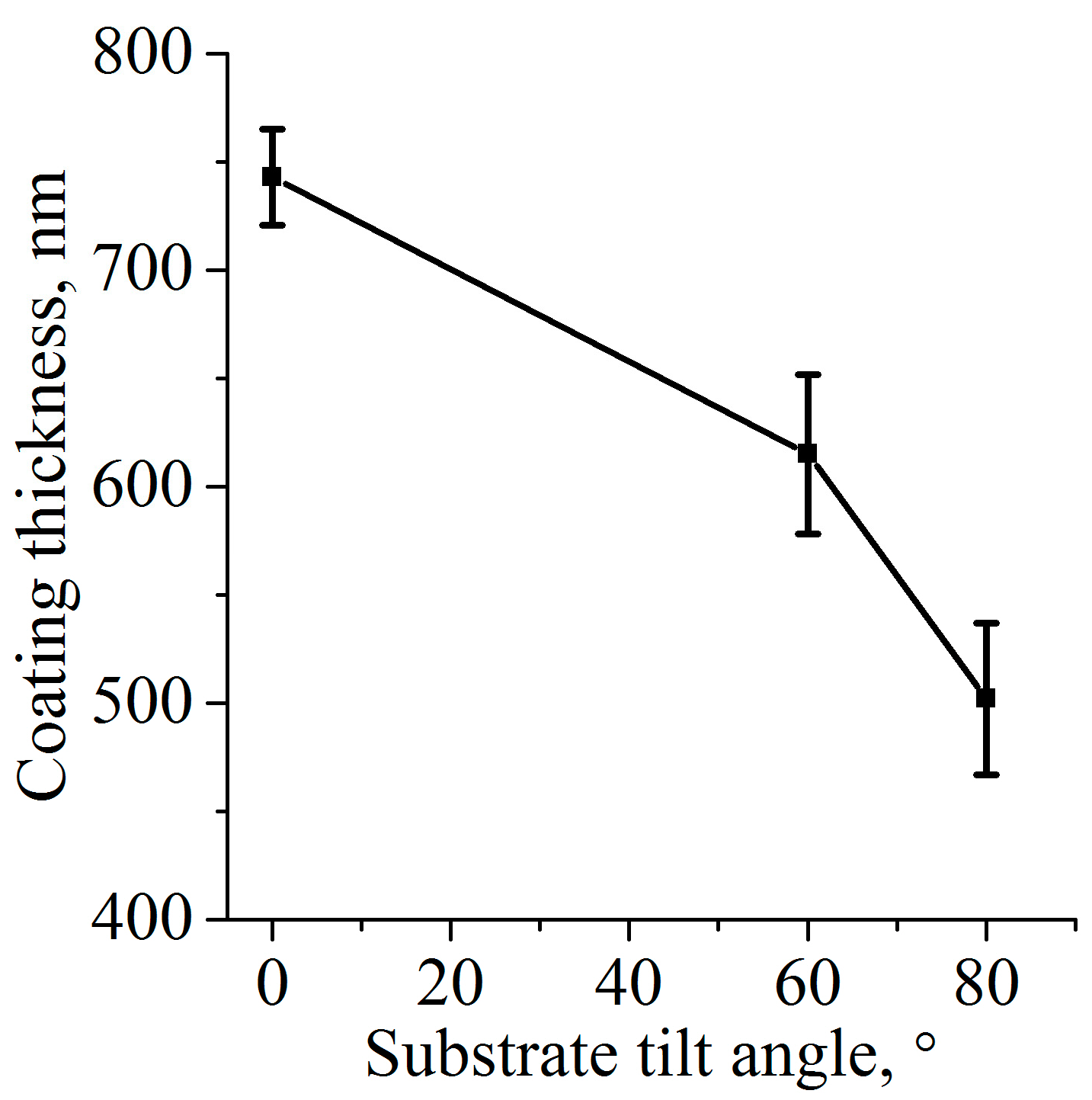
Even though research on GLAD coatings is evolving extensively, there are few reports on the coating uniformity of the substrate surface and the variation in its thickness. Here, we show the thickness variation on the Si substrates measured by ellipsometry. In Figure 2, the coating thickness of the substrates is placed in parallel to the target of the magnetron (0°), and inclination angles of 60° and 80° are presented.
With the increase in the inclination angle, the coating thickness decreases gradually. We believe that this effect is associated with substrate re-sputtering. It is known that when the substrate is in close proximity to the plasma source, impinging energetic ions of Ar+ and O induce re-sputtering of the coating from the substrate [28]. Moreover, the deposition parameters were chosen in such a way that the mean free path of the sputtered atoms was as large as possible while maintaining a relatively high power density. In this way, the kinetic energy of the sputtered material and the generated ions is close to the original level due to the negligible number of collisions they experience. It not only enables better adatom mobility, but also higher substrate heating and hence higher re-sputtering. In addition, a shorter target–substrate distance will increase the rate of deposition but at the expense of film uniformity [29]. This was the case for the CaP coatings deposited in our experiments. For the samples deposited at less than an inclination angle of 80°, the coating thickness was measured for the upper part (closer to the magnetron source) and the lower part of the sample. Ellipsometry showed that the coating thickness was inhomogeneous along the sample, and the thickness difference between the upper and lower part of the coating was up to 110 ± 25 nm for some samples. Interestingly, the closer the placement of the sample to the plasma source, the thinner the film deposited. We believe that this effect is due to substrate re-sputtering and energetic ions bombardment.

3.2. Effect of GLAD on Coating Topography and Roughness

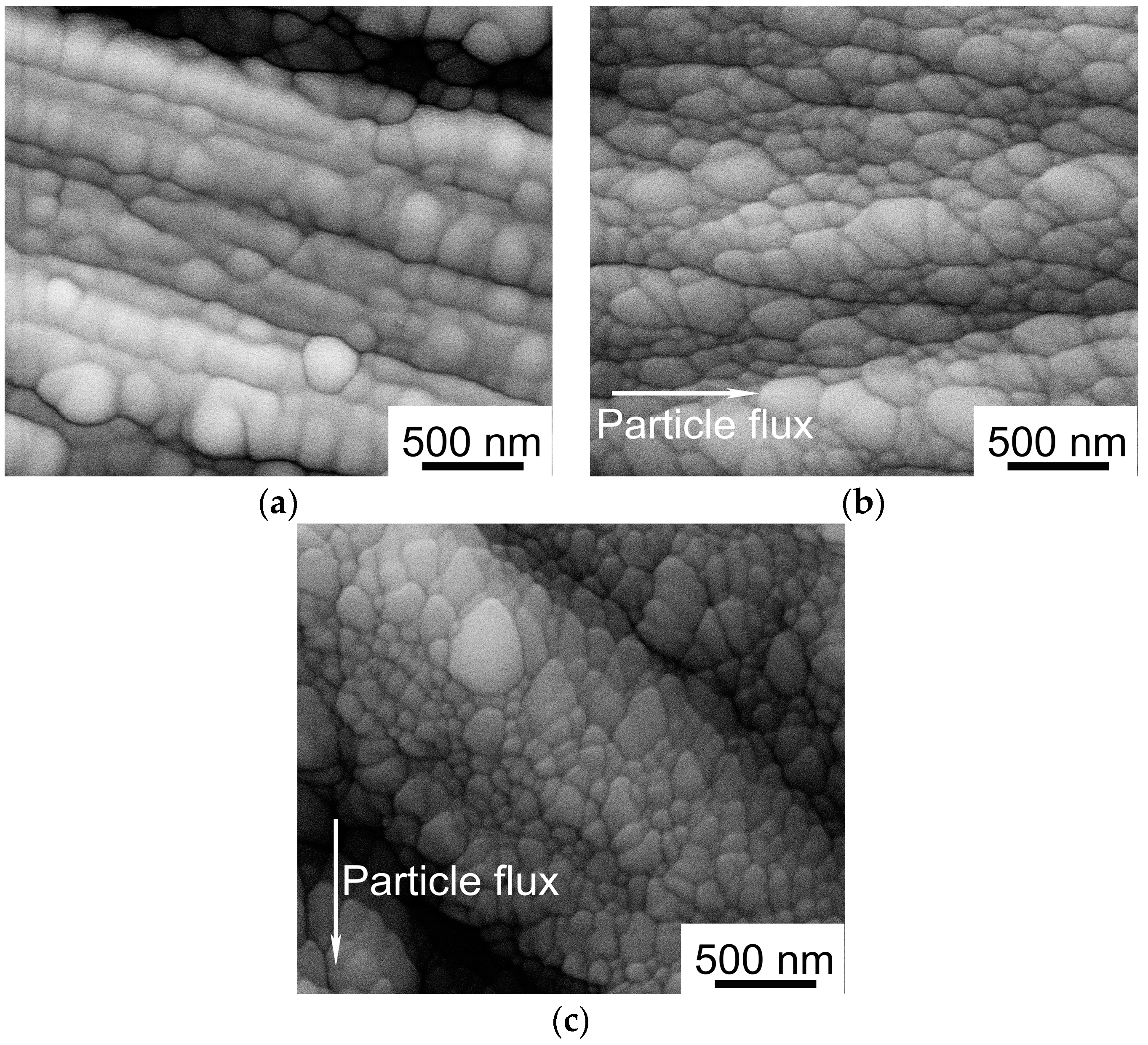
In Figure 3, SEM images show the topography of CaP coatings deposited at different angles of 0°, 60°, and 80°. The coatings deposited without tilting (0°) show globular-like surface features. The samples inclined at 60° during the deposition decreased in size, and the surface structure elements changed their shape. The surface grains were orientated along the incidence direction of the sputtered particles independent of working gas pressure. This effect was even more pronounced for the samples deposited at a tilt angle of 80°. An alteration in the working gas pressure led to a reduction in surface elements sizes. When the deposition process was performed at a lower working pressure (here: 0.8 mTorr), surface elements tended to be more homogeneously spread on the surface.
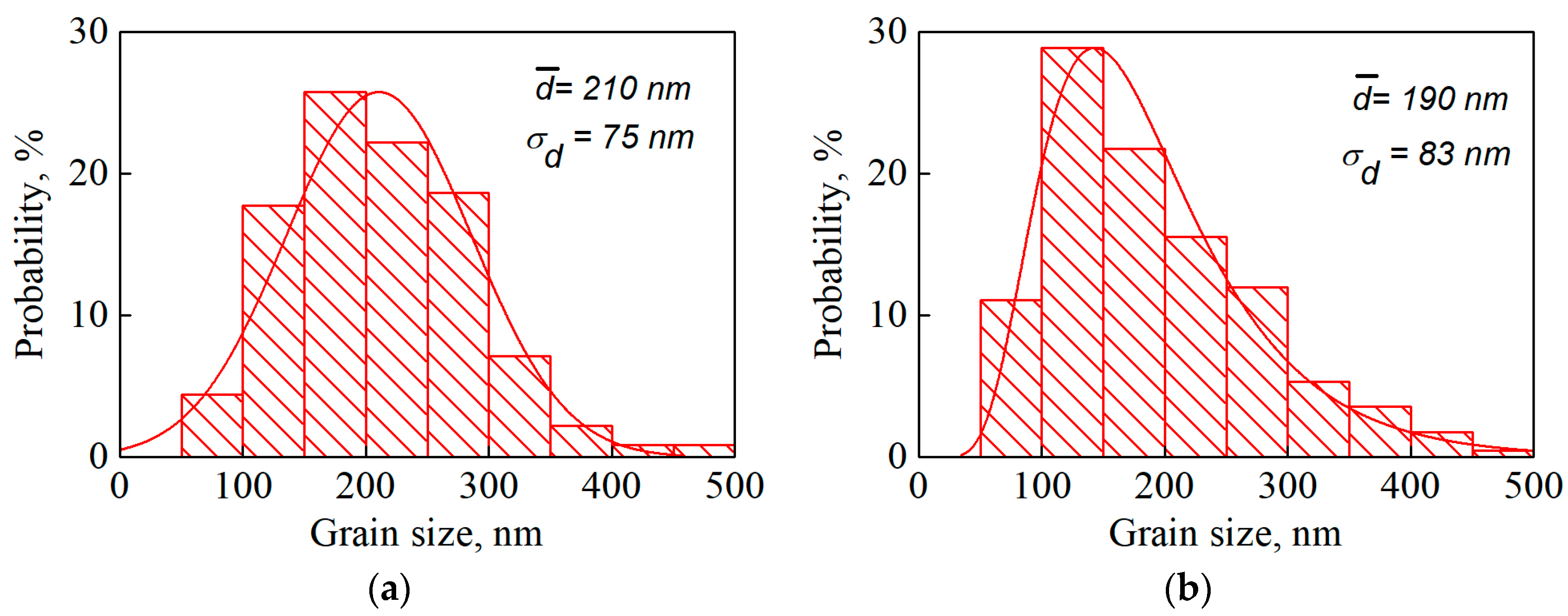
In Figure 4, the dispersion of the size of the surface features for the cases of GLAD at 0° and 80° is presented. The mean grain size of the coating decreased from 210 to 190 nm with the increasing tilt angle.
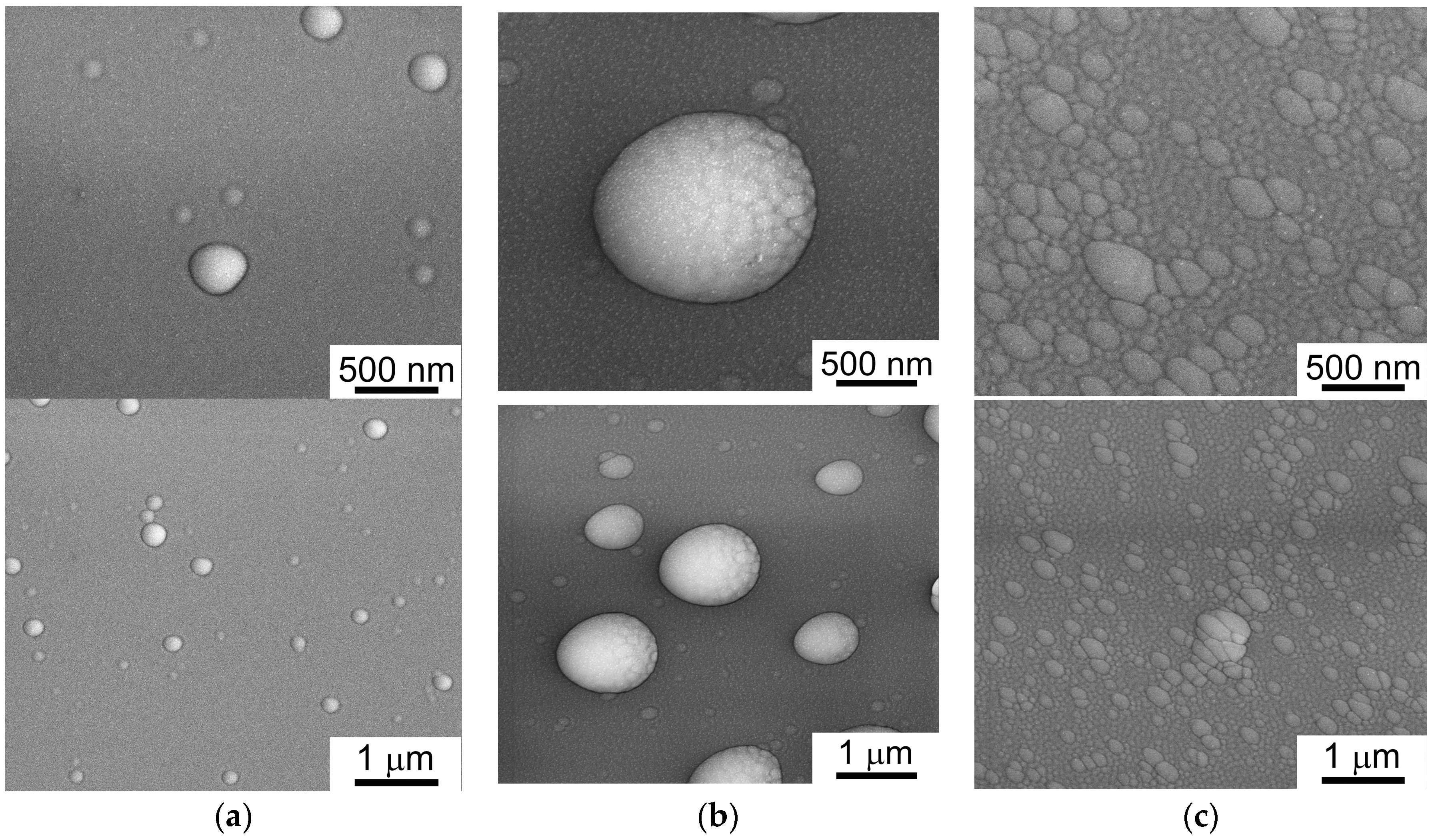
It is well known that the coating deposited by magnetron sputtering insignificantly changes the surface topography [52]. In most cases, the deposited coating repeats the topography of the initial substrate surface. Even after polishing, the Ti surface still had some marks after machining that could potentially disturb or alter the growth of the surface coating’s elements. Therefore, polished Si samples were used alongside the Ti substrates in all the deposition runs, as they do not provide additional ambiguity in the understanding of coating growth on a non-smooth surface topography. Figure 5 shows SEM images of CaP on the Si substrate deposited at 0°, 60°, and 80° tilt angles and at a pressure of 0.8 mTorr. This was the pressure that promoted the dispersion of the most homogeneous surface features and minimized the particle collision during deposition most effectively. Interestingly, the deposition of the CaP coating on polished Si resulted in the appearance of surface grains in smaller quantities. Apparently, the Ti surface with defects, cavities, and an overall rougher topography induced more nucleation sites for subsequent grain formation compared with Si.
Even though the initial surface of the Si samples was smooth and without pronounced defects or impurities, grain nucleation still took place in regions that were energetically favorable. Even though the surface of coated Si deposited at the normal incidence was rather smooth, it was possible to find rare globular-like shaped grains on its surface. In Figure 5, some of the grains that were found on the smooth surface of the sample deposited without tilting are shown. For samples deposited at an angle of 60°, the concentration of surface elements increased together with their size. Moreover, in some cases, grains were comprised of smaller structural elements and had complex topography. We assume that this could be a transition state before the grains coalescence into bigger surface structural elements. With an increase in tilt angle to 80°, the effect of self-shadowing became more pronounced and resulted in the appearance of surface grains of different sizes. In this case, the surface grains covered the whole surface of the sample and left no place for a region without complex topography. From this, we can conclude that an RF magnetron GLAD method for CaP can have a topographical effect on smooth and rough surfaces of different materials. Álvarez et al. [23] performed mathematical modeling with experimental validation for Ti thin films deposited by RF magnetron sputtering. The proposed model correlated well with the experimental results. It was solely based on ballistic deposition phenomena, indicating that the simulations realistically reproduced the competitive growth mechanism involved in GLAD experiments. However, a modeling of a far more complex structure (hydroxyapatite) still needs to be performed.
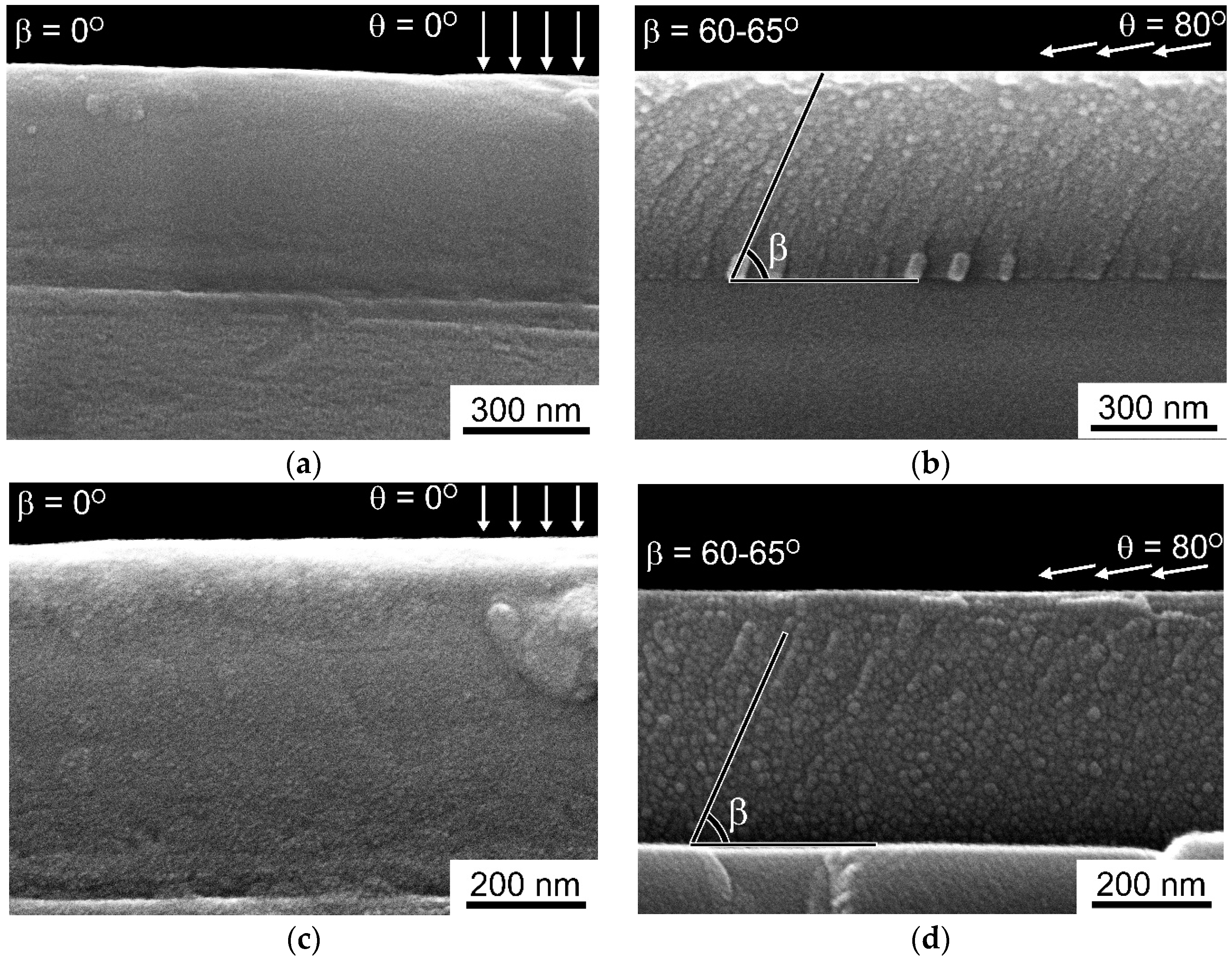
Figure 6 shows a cross-section SEM of thin films deposited under tilt angles of 0° (a) and 80° (b) at 100,000× magnification and films under tilt angles of 0° (c) and 80° (d) at 200,000× magnification on Si substrates. For the untilted samples, the cross section is presented by an amorphous calcium phosphate layer without any visible structural features. In contrast, coatings deposited at 80° inclination show an anisotropic, elongated type of inner structure orientated towards the particle source represented by small crystallites. EDX data obtained from both types of samples showed that the Ca/P ratio equals 1.8–1.9, while the content of Zn does not exceed 1 at.%. It is worth noting that the inner structure corresponds to the surface topography of the samples. In that way, the surface of the coatings deposited on the untilted samples is smooth with a few globular-like features (Figure 5a), and a cross-section of this sample (Figure 6a,c) is represented by smooth featureless layer. In the case of 80°, tilting small crystallites do not only belong to the surface (Figure 5b) but are also visible throughout the coatings’ inner structure (Figure 6b,c). Moreover, predominant growth towards the particle flux is detectable, and the angle of structural inclination β is calculated to be in the range of 60°–65°. As it is mentioned in the literature [53], the tilt angle is always smaller than the vapor incidence angle (β < θ). In the paper by Grüner et al. [53], it is stated that, as a first order approximation, a linear relationship between the tilt angle and the angle of incidence β ≅ 0.71θ can be obtained for GLAD of silicon. A similar, linear behavior can be found for obliquely deposited germanium and molybdenum thin films covering a wide range of melting points. However, we could speculate that, in our case, this coefficient is going to be in a range of 0.75–0.8 according to the SEM measurements. Taking into account the fact that the melting point of silicon (1414 °C) is relatively close to the melting point of hydroxyapatite (1570 °C) [54], this coefficient could indicate the differences in the lattices of the sputtered materials. Most published papers dealing with GLAD focused on materials with relatively simple oxide or monocrystal types of structures with a higher level of symmetry when compared with calcium phosphates. In turn, during the sputtering of CaP, various sputtered species travel to the substrate and are later are involved in the condensation step. Therefore, we assume that this fact is responsible for the difference in the calculated coefficient and overall difference in the thin film structure.
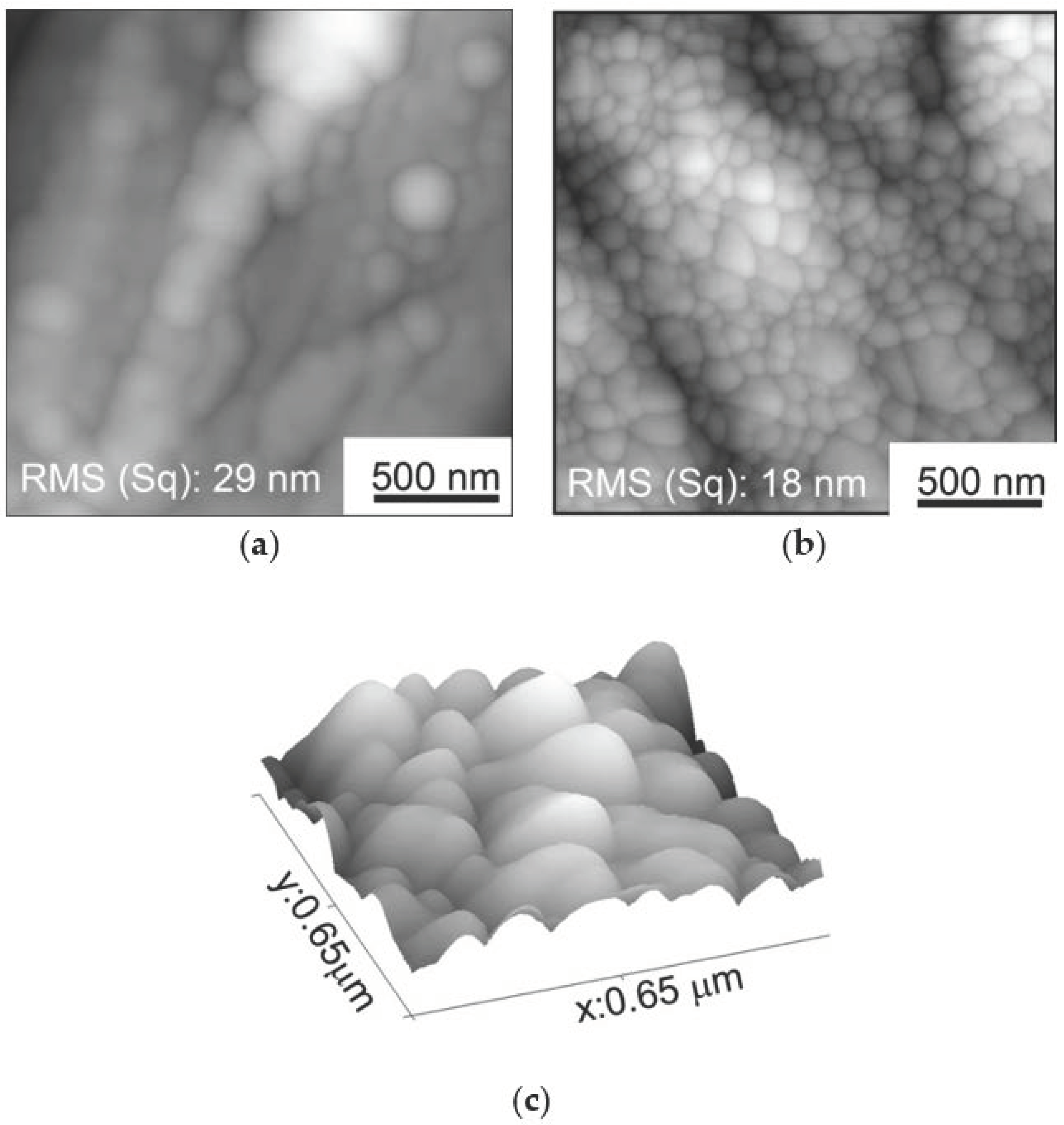
In Figure 7, an AFM visualization of CaP coatings deposited on Ti with and without tilting is shown. According to Sarkar and Pradhan [55], the RMS values of film roughness increase with the increasing oblique angle of deposition. However, in our case, the RMS for tilted samples were smaller than for samples without inclination: 17 nm for the 80° sample and 28 nm for the sample without inclination (0°), respectively. We believe that this is because small surface grains, which homogeneously cover the initial rough Ti surface, are reducing the RMS compared with the sample without any inclination. In the case of the normal incidence of sputtered particles, round-shaped grains are formed on top of the Ti surface, artificially increasing the RMS. AFM measurements allow us to have a 3D image of the surface topography and reveal an out-of-plane growth of surface grains (Figure 7c).
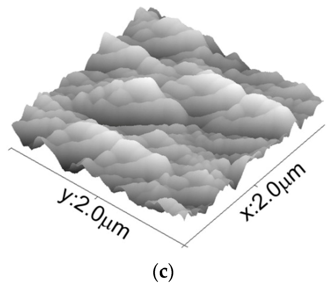
In order to exclude the impact of the substrates’ surface topography on the coating’s roughness, AFM measurements were performed for polished Si samples as well (Figure 8). For the samples deposited at the normal incidence, it was almost impossible to detect distinct surface features. In an untilted sample, some structural elements were found. Surface elements are represented in the form of pyramids, which possibly represent artifacts rather than the actual shape. Nevertheless, the RMS value for the untilted sample was very low (down to 200 pm).
However, the RMS of the GLAD sample was 5 nm, i.e., was significantly higher than that of the untilted sample. Moreover, these results are in good correlation with GLAD-related research, as RMS values are usually found to increase with the increasing oblique angle of deposition [24]. Such changes in morphology may lead to a significant decrease in the values of the contact angle of the coatings.

3.3. Effect of GLAD on Coating Crystallinity and Scratch Resistance

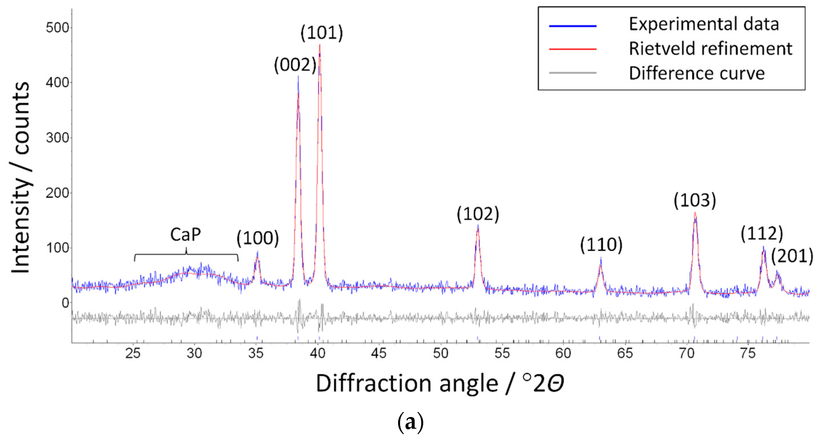
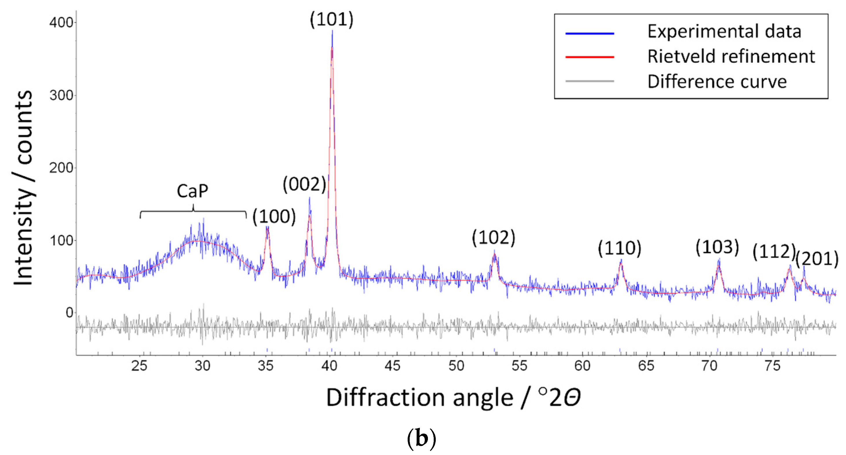
It is not rare that CaP coatings deposited by RF magnetron sputtering have a low level of crystallinity [56]. Frequently, CaP-deposited coatings are annealed in order to reveal peaks from crystalline Zn-HA [7]. However, in our case, we decided to perform a GIXRD of the untreated sample, as the temperature treatment will significantly change the internal structure of the CaP. Figure 9 shows representative X-ray powder diffraction patterns of the coatings deposited on Ti substrates at oblique angles of 0° and 80°. The GIXRD measurements indicate a formation of mostly amorphous CaP coating with a broad halo at 2θ = 30°, which can be attributed to hydroxyapatite with a crystallite size 2(1) nm as determined by the Rietveld refinement. The slightly increased intensity of the amorphous halo of the hydroxyapatite coating deposited under 80° (Figure 9b) compared with the hydroxyapatite coating under 0° might be caused by the increased crystallinity of the HA coating. The calculated lattice parameters of Ti (a = 2.951 and c = 4.685 Å) agree well with the ICDD database, confirming that the RF magnetron sputtering does not change the structure of the metallic substrate (as expected). Only a small difference between the Ti substrates was observed in the intensity of diffraction peak (002) at 2θ = 38.4°, which was caused by the typical rolling texture in hexagonal metals, including Ti [57,58,59]. It is worth noting, that the increased crystallinity of the samples inclined to 80° correlates with the formation of small-sized crystallites on the surface and in the cross-section structure of the GLAD samples (Figure 6b,d).
In Figure 10, the results of CaP coating scratching are shown. Thin film adherence is one of the most important aspects when dealing with physical vapor deposition methods. Lc (critical load) is a function of coating–substrate adhesion, but also involves other parameters related to the shape of the stylus, the mechanical properties of the substrate and the coating, the thickness, and the internal stress. In Figure 10a, a micro-scratch on the surface of the Zn-doped CaP coating on the untilted sample is represented. The Lc was determined during the scratch test to be a relatively small load of 10 N. The first adhesive cracks were observed after Lc = 5.3 N for the untilted sample. The average value of the friction coefficient during the measurements was calculated to be 0.3.
Local detachment of the coating is seen on the side of the track and in several other regions that are identified by arrows in Figure 10a. We concluded that the coating demonstrates sufficient scratch resistance, which is in accordance with the scientific data available in the literature [60,61]. In contrast, samples deposited at inclinations of 60° and 80° (Figure 10b,c) show higher scratch resistance. Thus, coating delamination even at the maximum load of 10 N is not observed. The average value of the friction coefficient for both the tilted substrates during the measurements did not exceed 0.25. This fact also contributed to the observed, improved scratch resistance of the tilted samples. We associate these results with the high energy of sputtered species impinging the substrate during the condensation phase because of the placement of the inclined substrate closer to the particle source. The influence of bombardment energy on the level of scratch resistance can also be found in the literature [62].

4. Conclusions

Two approaches for achieving a possible synergetic antibacterial effect by manufacturing a patterned surface of Zn-doped calcium phosphate using GLAD technique in RF magnetron sputtering were used. Two types of substrates (Ti and Si) with significantly different roughness were chosen. Variations in coating thickness and uniformity take place starting from a tilt angle of 60°. It was shown that it is possible to manipulate the surface roughness and morphology of the coatings by varying the substrate tilt angle. The columnar structure becomes more prominent at an oblique angle of 80°, and it is made of inclined Zn-doped CaP columns. A significant change in the coating morphology becomes obvious starting from the substrate tilt angle of 60°. An increase in the coating crystallinity for samples deposited at a tilt angle of 80° corresponds to the formation of crystallites in the bulk structure of the thin film. It was shown that GLAD is a powerful technique that allows for the variation of CaP thin film morphology and can be utilized to create self-organized nanostructures that can be used for synergetic antibacterial effect.

Author Contributions

Conceptualization, K.A.P.; Data curation, K.A.P., O.A.B., J.L., K.L., and O.P.; Formal analysis, K.A.P., J.L., and O.P.; Funding acquisition, C.M., J.V.R., M.E., and Y.P.S.; Investigation, K.A.P., O.A.B., J.L., K.L., and O.P.; Project administration, O.P., C.M., M.E., and Y.P.S.; Supervision, C.M., M.E., and Y.P.S.; Validation, C.M., J.V.R., and Y.P.S.; Visualization, K.A.P.; Original draft, K.A.P.; Review and editing of final manuscript, K.L., O.P., C.M., J.V.R., M.E., and Y.P.S.

Funding

This research was funded by the state program of fundamental research of Russian Academy of Science for 2017–2020, direction of research III.23.; Tomsk Polytechnic University Competitiveness Enhancement Program grant, Project Number TPU CEP_INDT_91/2018, and the German Academic Exchange Service (DAAD; Leonhard-Euler program).

Acknowledgments

The authors thank V .   Kanaev and M. Khimich for their support of the research. The authors thank S. Boukercha (University of Duisburg-Essen, Essen, Germany) for assistance in SEM measurements. The authors also would like to thank M. Chaikina from the Institute of Solid State Chemistry and Mechanochemistry of SB RAS, Novosibirsk, Russia, for synthesizing the Zn-HA powder.

Conflicts of Interest

The authors declare no conflicts of interest.

References

  1. Li, J.; Yang, L.; Guo, X.; Cui, W.; Yang, S.; Wang, J.; Qu, Y.; Shao, Z.; Xu, S. Osteogenesis effects of strontium-substituted hydroxyapatite coatings on true bone ceramic surfaces in vitro and in vivo. Biomed. Mater. 2018, 13, 015018. [Google Scholar] [CrossRef]
  2. Vladescu, A.; Surmenev, R.; Surmeneva, M.; Braic, M.; Ivanova, A.; Grubova, I.; Cotrut, C.M. Radio frequency magnetron sputter deposition as a tool for surface modification of medical implants. In Modern Technologies for Creating the Thin-Film Systems and Coatings; Nikitenkov, N., Ed.; InTech: Rijeka, Croatia, 2017. [Google Scholar]
  3. Raphel, J.; Holodniy, M.; Goodman, S.B.; Heilshorn, S.C. Multifunctional coatings to simultaneously promote osseointegration and prevent infection of orthopaedic implants. Biomaterials 2016, 84, 301–314. [Google Scholar] [CrossRef] [PubMed]
  4. Šupová, M. Substituted hydroxyapatites for biomedical applications: A review. Ceram. Int. 2015, 41, 9203–9231. [Google Scholar] [CrossRef]
  5. Rau, J.V.; Cacciotti, I.; De Bonis, A.; Fosca, M.; Komlev, V.S.; Latini, A.; Santagata, A.; Teghil, R. Fe-doped hydroxyapatite coatings for orthopedic and dental implant applications. Appl. Surf. Sci. 2014, 307, 301–305. [Google Scholar] [CrossRef]
  6. Graziani, G.; Bianchi, M.; Sassoni, E.; Russo, A.; Marcacci, M. Ion-substituted calcium phosphate coatings deposited by plasma-assisted techniques: A review. Mater. Sci. Eng. C 2017, 74, 219–229. [Google Scholar] [CrossRef]
  7. Robinson, L.; Salma-Ancane, K.; Stipniece, L.; Meenan, B.J.; Boyd, A.R. The deposition of strontium and zinc Co-substituted hydroxyapatite coatings. J. Mater. Sci. Mater. Med. 2017, 28, 51. [Google Scholar] [CrossRef]
  8. Koo, H.; Allan, R.N.; Howlin, R.P.; Stoodley, P.; Hall-Stoodley, L. Targeting microbial biofilms: Current and prospective therapeutic strategies. Nat. Rev. Microbiol. 2017, 15, 740–755. [Google Scholar] [CrossRef] [PubMed]
  9. Geng, Z.; Cui, Z.; Li, Z.; Zhu, S.; Liang, Y.; Liu, Y.; Li, X.; He, X.; Yu, X.; Wang, R.; et al. Strontium incorporation to optimize the antibacterial and biological characteristics of silver-substituted hydroxyapatite coating. Mater. Sci. Eng. C 2016, 58, 467–477. [Google Scholar] [CrossRef]
  10. Huang, Y.; Zhang, X.; Zhao, R.; Mao, H.; Yan, Y.; Pang, X. Antibacterial efficacy, corrosion resistance, and cytotoxicity studies of copper-substituted carbonated hydroxyapatite coating on titanium substrate. J. Mater. Sci. 2015, 50, 1688–1700. [Google Scholar] [CrossRef]
  11. Peñaflor Galindo, T.G.; Kataoka, T.; Fujii, S.; Okuda, M.; Tagaya, M. Preparation of nanocrystalline zinc-substituted hydroxyapatite films and their biological properties. Colloids Interface Sci. Commun. 2016, 10, 15–19. [Google Scholar] [CrossRef]
  12. Litvinova, L.S.; Shupletsova, V.V.; Dunets, N.A.; Khaziakhmatova, O.G.; Yurova, K.A.; Khlusova, M.Y.; Slepchenko, G.B.; Cherempey, E.G.; Sharkeev, Y.P.; Komarova, E.G.; et al. Imbalance of morphofunctional responses of Jurkat T lymphoblasts at short-term culturing with relief zinc- or copper-containing calcium phosphate coating on titanium. Dokl. Biochem. Biophys. 2017, 472, 35–39. [Google Scholar] [CrossRef]
  13. Graziani, G.; Boi, M.; Bianchi, M. A Review on Ionic Substitutions in Hydroxyapatite Thin Films: Towards Complete Biomimetism. Coatings 2018, 8, 269. [Google Scholar] [CrossRef]
  14. Rau, J.V.; Cacciotti, I.; Laureti, S.; Fosca, M.; Varvaro, G.; Latini, A. Bioactive, nanostructured Si-substituted hydroxyapatite coatings on titanium prepared by pulsed laser deposition. J. Biomed. Mater. Res. B Appl. Biomater. 2015, 103, 1621–1631. [Google Scholar] [CrossRef] [PubMed]
  15. Modaresifar, K.; Azizian, S.; Ganjian, M.; Fratila-Apachitei, L.E.; Zadpoor, A.A. Bactericidal effects of nanopatterns: A systematic review. Acta Biomater. 2018, 83, 29–36. [Google Scholar] [CrossRef]
  16. Yu, W.; Sun, T.W.; Qi, C.; Ding, Z.; Zhao, H.; Zhao, S.; Shi, Z.; Zhu, Y.J.; Chen, D.; He, Y. Evaluation of zinc-doped mesoporous hydroxyapatite microspheres for the construction of a novel biomimetic scaffold optimized for bone augmentation. Int. J. Nanomed. 2017, 12, 2293–2306. [Google Scholar] [CrossRef] [PubMed] [Green Version]
  17. Costa, D.O.; Prowse, P.D.H.; Chrones, T.; Sims, S.M.; Hamilton, D.W.; Rizkalla, A.S.; Dixon, S.J. The differential regulation of osteoblast and osteoclast activity bysurface topography of hydroxyapatite coatings. Biomaterials 2013, 34, 7215–7226. [Google Scholar] [CrossRef] [PubMed]
  18. Rau, J.V.; Generosi, A.; Laureti, S.; Komlev, V.S.; Ferro, D.; Cesaro, S.N.; Paci, B.; Albertini, V.R.; Agostinelli, E.; Barinov, S.M. Physicochemical investigation of pulsed laser deposited carbonated hydroxyapatite films on titanium. ACS Appl. Mater. Interfaces 2009, 1, 1813–1820. [Google Scholar] [CrossRef]
  19. Kim, H.N.; Jiao, A.; Hwang, N.S.; Kim, M.S.; Kang, D.H.; Kim, D.H.; Suh, K.Y. Nanotopography-guided tissue engineering and regenerative medicine. Adv. Drug Deliv. Rev. 2013, 65, 536–558. [Google Scholar] [CrossRef] [PubMed] [Green Version]
  20. Chen, Z.; Bachhuka, A.; Wei, F.; Wang, X.; Liu, G.; Vasilev, K.; Xiao, Y. Nanotopography-based strategy for the precise manipulation of osteoimmunomodulation in bone regeneration. Nanoscale 2017, 9, 18129–18152. [Google Scholar] [CrossRef]
  21. Lee, L.C.Y.; Gadegaard, N.; de Andrés, M.C.; Turner, L.A.; Burgess, K.V.; Yarwood, S.J.; Wells, J.; Salmeron-Sanchez, M.; Meek, D.; Oreffo, R.O.C.; et al. Nanotopography controls cell cycle changes involved with skeletal stem cell self-renewal and multipotency. Biomaterials 2017, 116, 10–20. [Google Scholar] [CrossRef]
  22. Karazisis, D.; Petronis, S.; Agheli, H.; Emanuelsson, L.; Norlindh, B.; Johansson, A.; Rasmusson, L.; Thomsen, P.; Omar, O. The influence of controlled surface nanotopography on the early biological events of osseointegration. Acta Biomater. 2017, 53, 559–571. [Google Scholar] [CrossRef] [PubMed]
  23. Alvarez, R.; Garcia-Martin, J.M.; Garcia-Valenzuela, A.; Macias-Montero, M.; Ferrer, F.J.; Santiso, J.; Rico, V.; Cotrino, J.; Gonzalez-Elipe, A.R.; Palmero, A. Nanostructured Ti thin films by magnetron sputtering at oblique angles. J. Phys. D. Appl. Phys. 2015, 49, 045303. [Google Scholar] [CrossRef] [Green Version]
  24. Li, Z.; Xing, L.; Zhang, N.; Yang, Y.; Zhang, Z. Preparation and Photocatalytic Property of TiO2 Columnar Nanostructure Films. Mater. Trans. 2011, 52, 1939–1942. [Google Scholar] [CrossRef]
  25. Garcia-Valenzuela, A.; Alvarez, R.; Rico, V.; Cotrino, J.; Gonzalez-Elipe, A.R.; Palmero, A. Growth of nanocolumnar porous TiO2 thin films by magnetron sputtering using particle collimators. Surf. Coat. Technol. 2017, 343, 172–177. [Google Scholar] [CrossRef]
  26. Sit, J.C.; Vick, D.; Robbie, K.; Brett, M.J. Thin film microstructure control using glancing angle deposition by sputtering. J. Mater. Res. 1999, 14, 1197–1199. [Google Scholar] [CrossRef]
  27. Zhao, Y.; Ye, D.; Wang, G.-C.; Lu, T.-M. Designing nanostructures by glancing angle deposition. Proc. SPIE Nanotub. Nanowires 2003, 5219, 59–73. [Google Scholar] [CrossRef]
  28. Barranco, A.; Borras, A.; Gonzalez-Elipe, A.R.; Palmero, A. Perspectives on oblique angle deposition of thin films: From fundamentals to devices. Prog. Mater. Sci. 2016, 76, 59–153. [Google Scholar] [CrossRef] [Green Version]
  29. Renault, C.; Harris, K.D.; Brett, M.J.; Balland, V.; Limoges, B. Time-resolved UV-visible spectroelectrochemistry using transparent 3D-mesoporous nanocrystalline ITO electrodes. Chem. Commun. 2011, 47, 1863–1865. [Google Scholar] [CrossRef]
  30. Larsen, G.K.; Fitzmorris, R.; Zhang, J.Z.; Zhao, Y. Structural, optical, and photocatalytic properties of Cr:TiO2 nanorod array fabricated by oblique angle codeposition. J. Phys. Chem. C 2011, 115, 16892–16903. [Google Scholar] [CrossRef]
  31. Schubert, M.F.; Xi, J.Q.; Kim, J.K.; Schubert, E.F. Distributed Bragg reflector consisting of high- and low-refractive-index thin film layers made of the same material. Appl. Phys. Lett. 2007, 90, 141115. [Google Scholar] [CrossRef] [Green Version]
  32. Rider, D.A.; Tucker, R.T.; Worfolk, B.J.; Krause, K.M.; Lalany, A.; Brett, M.J.; Buriak, J.M.; Harris, K.D. Indium tin oxide nanopillar electrodes in polymer/fullerene solar cells. Nanotechnology 2011, 22, 085706. [Google Scholar] [CrossRef]
  33. Jensen, M.O.; Brett, M.J. Porosity engineering in glancing angle deposition thin films. Appl. Phys. A Mater. Sci. Process. 2005, 80, 763–768. [Google Scholar] [CrossRef]
  34. Lintymer, J.; Martin, N.; Chappe, J.M.; Takadoum, J. Glancing angle deposition to control microstructure and roughness of chromium thin films. Wear 2008, 264, 444–449. [Google Scholar] [CrossRef]
  35. Hung, K.-Y.; Lai, H.-C.; Feng, H.-P. Characteristics of RF-Sputtered Thin Films of Calcium Phosphate on Titanium Dental Implants. Coatings 2017, 7, 126. [Google Scholar] [CrossRef]
  36. Surmenev, R.A.; Surmeneva, M.A.; Grubova, I.Y.; Chernozem, R.V.; Krause, B.; Baumbach, T.; Loza, K.; Epple, M. RF magnetron sputtering of a hydroxyapatite target: A comparison study on polytetrafluorethylene and titanium substrates. Appl. Surf. Sci. 2017, 414, 335–344. [Google Scholar] [CrossRef]
  37. Thian, E.S.; Konishi, T.; Kawanobe, Y.; Lim, P.N.; Choong, C.; Ho, B.; Aizawa, M. Zinc-substituted hydroxyapatite: A biomaterial with enhanced bioactivity and antibacterial properties. J. Mater. Sci. Mater. Med. 2013, 24, 437–445. [Google Scholar] [CrossRef] [PubMed]
  38. Prosolov, K.A.; Belyavskaya, O.A.; Muehle, U.; Sharkeev, Y.P. Thin bioactive Zn substituted hydroxyapatite coating deposited on ultrafine-grained titanium substrate: Structure analysis. Front. Mater. 2018, 5, 3. [Google Scholar] [CrossRef]
  39. Prosolov, K.A.; Belyavskaya, O.A.; Rau, J.V.; Sharkeev, Y.P. Thin bioactive Zn-substituted hydroxyapatite coating deposited on Ti substrate by radiofrequency sputtering. High Temp. Mater. Process. 2017, 21, 3. [Google Scholar] [CrossRef]
  40. Solar, P.; Choukourov, A.; Hanus, J.; Pavlova, E.; Slavinska, D.; Biederman, H. Nanocomposite structured thin films by magnetron sputtering at glancing angle deposition. In Proceedings of the International Plasma Chemistry Society, Bochum, Germany, 27–31 July 2009; p. 226. [Google Scholar]
  41. Pang, H.F.; Zhang, G.A.; Tang, Y.L.; Fu, Y.Q.; Wang, L.P.; Zu, X.T.; Placido, F. Substrate-tilt angle effect on structural and optical properties of sputtered ZnO film. Appl. Surf. Sci. 2012, 259, 747–753. [Google Scholar] [CrossRef]
  42. Toledano, D.; Galindo, R.E.; Yuste, M.; Albella, J.M.; Sánchez, O. Compositional and structural properties of nanostructured ZnO thin films grown by oblique angle reactive sputtering deposition: Effect on the refractive index. J. Phys. D Appl. Phys. 2013, 46, 045306. [Google Scholar] [CrossRef]
  43. Leem, J.W.; Yu, J.S. Structural, optical, and electrical properties of AZO films by tilted angle sputtering method. Thin Solid Films 2010, 518, 6285–6288. [Google Scholar] [CrossRef]
  44. García-Martín, J.M.; Alvarez, R.; Romero-Gómez, P.; Cebollada, A.; Palmero, A. Tilt angle control of nanocolumns grown by glancing angle sputtering at variable argon pressures. Appl. Phys. Lett. 2010, 97, 173103. [Google Scholar] [CrossRef] [Green Version]
  45. Siad, A.; Besnard, A.; Nouveau, C.; Jacquet, P. Critical angles in DC magnetron glad thin films. Vacuum 2016, 131, 305–311. [Google Scholar] [CrossRef] [Green Version]
  46. Park, Y.J.; Sobahan, K.M.A.; Nam, H.J.; Kim, J.J.; Hwangbo, C.K. Optical and structural properties of ZnO thin films fabricated by using oblique angle deposition. J. Korean Phys. Soc. 2010, 57, 1657–1660. [Google Scholar]
  47. Bolbasov, E.N.; Maryin, P.V.; Stankevich, K.S.; Kozelskaya, A.I.; Shesterikov, E.V.; Khodyrevskaya, Y.I.; Nasonova, M.V.; Shishkova, D.K.; Kudryavtseva, Y.A.; Anissimov, Y.G.; et al. Surface modification of electrospun poly-(L-lactic) acid scaffolds by reactive magnetron sputtering. Colloids Surf. B Biointerfaces 2018, 162, 43–51. [Google Scholar] [CrossRef]
  48. Bolbasov, E.N.; Antonova, L.V.; Stankevich, K.S.; Ashrafov; Matveeva, V.G.; Velikanova, E.A.; Khodyrevskaya, Y.I.; Kudryavtseva, Y.A.; Anissimov, Y.G.; Tverdokhlebov, S.I.; et al. The use of magnetron sputtering for the deposition of thin titanium coatings on the surface of bioresorbable electrospun fibrous scaffolds for vascular tissue engineering: A pilot study. Appl. Surf. Sci. 2017, 398, 63–72. [Google Scholar] [CrossRef]
  49. Ivanova, A.A.; Surmeneva, M.A.; Surmenev, R.A.; Depla, D. Structural evolution and growth mechanisms of RF-magnetron sputter-deposited hydroxyapatite thin films on the basis of unified principles. Appl. Surf. Sci. 2017, 425, 497–506. [Google Scholar] [CrossRef]
  50. Chu, J.; Peng, X.; Sajjad, M.; Yang, B.; Feng, P.X. Nanostructures and sensing properties of ZnO prepared using normal and oblique angle deposition techniques. Thin Solid Films 2012, 520, 3493–3498. [Google Scholar] [CrossRef]
  51. Black, D.R.; Windover, D.; Henins, A.; Filliben, J.; Cline, J.P. Certification of Standard Reference Material 1976B. Powder Diffr. 2015, 30, 199–204. [Google Scholar] [CrossRef]
  52. Ter Brugge, P.J.; Wolke, J.G.C.; Jansen, J.A. Effect of calcium phosphate coating crystallinity and implant surface roughness on differentiation of rat bone marrow cells. J. Biomed. Mater. Res. 2002, 60, 70–78. [Google Scholar] [CrossRef]
  53. Gruener, C.; Liedtke, S.; Bauer, J.; Mayr, S.G.; Rauschenbach, B. Morphology of thin films formed by oblique physical vapor deposition. ACS Appl. Nano Mater. 2018, 1, 1370–1376. [Google Scholar] [CrossRef]
  54. Gross, K.; Berndt, C. Thermal processing of hydroxyapatite for coating production. J. Biomed. Mater. Res. 1998, 39, 580–587. [Google Scholar] [CrossRef] [Green Version]
  55. Sarkar, S.; Pradhan, S.K. Tailoring of optical and wetting properties of sputter deposited silica thin films by glancing angle deposition. Appl. Surf. Sci. 2014, 290, 509–513. [Google Scholar] [CrossRef]
  56. Yonggang, Y.; Wolke, J.G.C.; Yubao, L.; Jansen, J.A. The influence of discharge power and heat treatment on calcium phosphate coatings prepared by RF magnetron sputtering deposition. J. Mater. Sci. Mater. Med. 2007, 18, 1061–1069. [Google Scholar] [CrossRef] [PubMed] [Green Version]
  57. Jiang, H.T.; Liu, J.X.; Mi, Z.L.; Zhao, A.M.; Bi, Y.J. Texture evolution of commercial pure Ti during cold rolling and recrystallization annealing. Int. J. Miner. Metall. Mater. 2012, 19, 530–535. [Google Scholar] [CrossRef]
  58. Ghosh, A.; Gurao, N.P. Effect of crystallographic texture on ratcheting response of commercially pure titanium. Mater. Des. 2017, 115, 121–132. [Google Scholar] [CrossRef]
  59. Grubova, I.Y.; Surmeneva, M.A.; Ivanova, A.A.; Kravchuk, K.; Prymak, O.; Epple, M.; Buck, V.; Surmenev, R.A. The effect of patterned titanium substrates on the properties of silver-doped hydroxyapatite coatings. Surf. Coat. Technol. 2015, 276, 595–601. [Google Scholar] [CrossRef]
  60. Surmeneva, M.A.; Sharonova, A.A.; Chernousova, S.; Prymak, O.; Loza, K.; Tkachev, M.S.; Shulepov, I.A.; Epple, M.; Surmenev, R.A. Incorporation of silver nanoparticles into magnetron-sputtered calcium phosphate layers on titanium as an antibacterial coating. Colloids Surf. B Biointerfaces 2017, 156, 104–113. [Google Scholar] [CrossRef]
  61. Syromotina, D.S.; Surmeneva, M.A.; Gorodzha, S.N.; Pichugin, V.F.; Ivanova, A.A.; Grubova, I.Y.; Kravchuk, K.S.; Gogolinskii, K.V.; Prymak, O.; Epple, M.; et al. Physical-mechanical characteristics of RF magnetron sputter-deposited coatings based on silver-doped hydroxyapatite. Russ. Phys. J. 2014, 56, 1198–1205. [Google Scholar] [CrossRef]
  62. Melnik, Y.A.; Metel, A.S. Improvement of the magnetron sputtered coating adhesion through pulsed bombardment by high-energy ions. J. Phys. Conf. Ser. 2017, 830, 012099. [Google Scholar] [CrossRef] [Green Version]
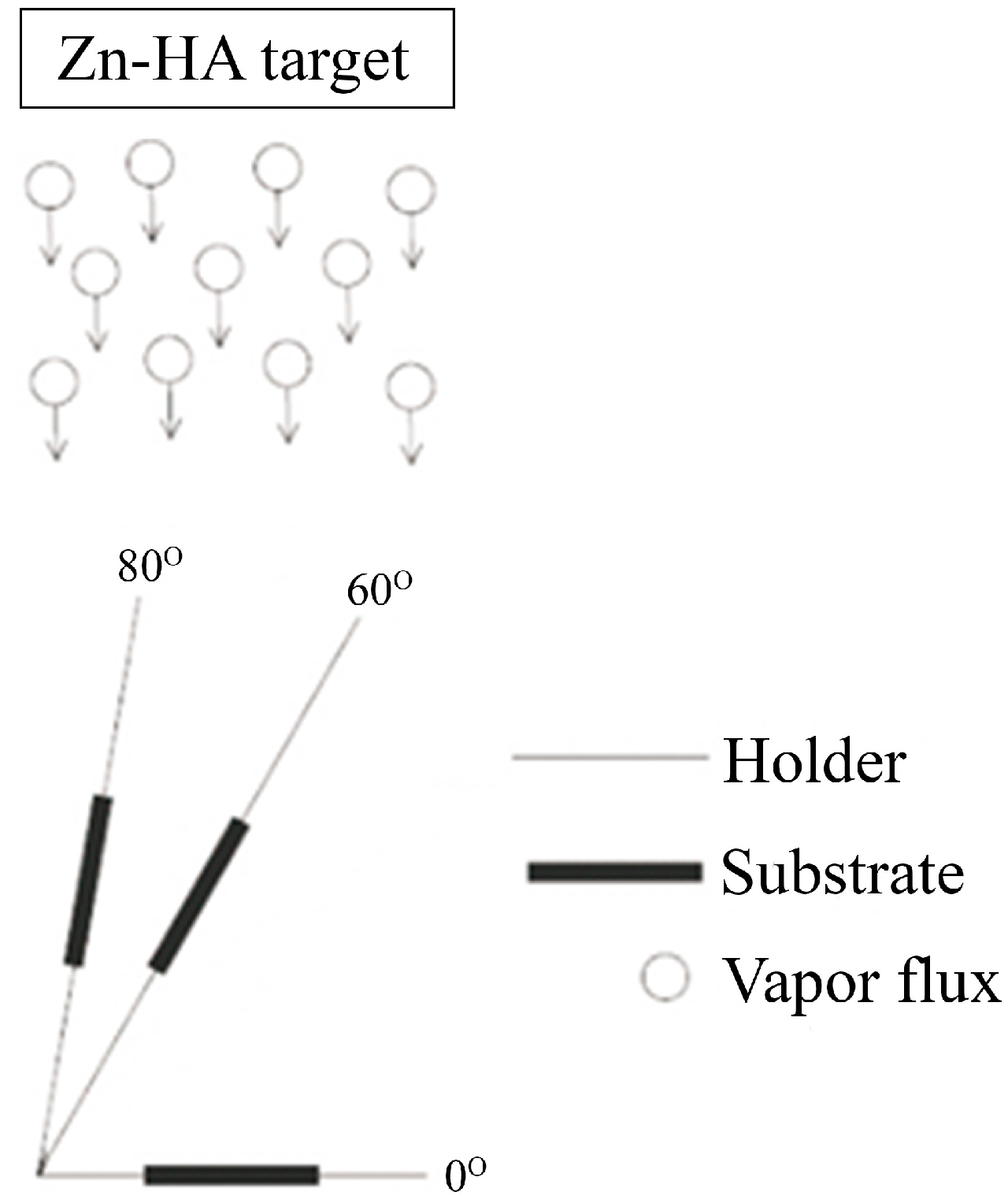
Figure 1. Schematic image of the deposition process of the Ti and Si samples with varying particle incidence angles at 0°, 60°, and 80° during the radiofrequency (RF) magneton sputtering of a Zn-substituted hydroxyapatite (Zn-HA) target with the arrows indicating the direction of the flux.
Coatings 09 00220 g001
Figure 2. Plot of the coating thickness against the substrate tilt angle.
Coatings 09 00220 g002
Figure 3. Calcium phosphate (CaP) coatings deposited on Ti at a working gas pressure of 0.8 mTorr under tilt angles of 0° (a), 60° (b), and 80° (c).
Coatings 09 00220 g003
Figure 4. Dispersion of coating surface grain sizes for samples deposited under tilt angles of 0° (a) and 80° (b) at a working gas pressure of 0.8 mTorr.
Coatings 09 00220 g004
Figure 5. CaP coatings deposited on Si at a working gas pressure of 0.8 mTorr under tilt angles of 0° (a), 60° (b), or 80° (c) on the Si substrates.
Coatings 09 00220 g005
Figure 6. SEM cross-section images of obliquely deposited Zn-doped CaP thin films deposited on Si under tilt angles of 0° (a) and 80° (b) at 100,000× magnification and films under tilt angles of 0° (c) and 80° (d) at 200,000× magnification on Si substrates, demonstrating significant changes in the film morphology. The arrows indicate the angle of incidence θ. The columns are tilted by angle β.
Coatings 09 00220 g006
Figure 7. CaP coatings deposited on Ti at a working gas pressure of 0.8 mTorr under tilt angles of 0° (a) and 80° (b) and three-dimensional (3D) visualization of coating deposited under 80° showing the out-of-plane growth of grains (c).
Coatings 09 00220 g007
Figure 8. CaP coatings deposited on Si at a working gas pressure of 0.8 mTorr under inclination angles of 0° (a) and 80° (b) and 3D visualization of coating deposited under 80° (c).
Coatings 09 00220 g008aCoatings 09 00220 g008b
Figure 9. Representative X-ray powder diffractograms (with Rietveld refinement) of CaP coatings deposited on the Ti substrate perpendicular to the flux at 0° (a) and inclined at 80° (b). The diffraction peaks of HA and Ti (with Miller indices) are shown.
Coatings 09 00220 g009aCoatings 09 00220 g009b
Figure 10. Optical microscopy of the tracks after scratch testing of the CaP coatings deposited on Ti at a working gas pressure of 0.8 mTorr under inclination angles of 0° (a), 60° (b), and 80° (c).
Coatings 09 00220 g010
Table 1. Deposition parameters and coating properties for glancing angle deposition (GLAD) with magnetron sputtering from the literature.
Ref.MethodAim of ResearchTargetSubstrateDeposition ParametersResult
[23]DC magnetron sputteringThe expansion of the well-known model of the Thornton spatial zone, including the inclination angle of the substrate as an additional degree of freedomTiSi (100)L = 22 cmFor α = 70°, a columnar morphology was formed consisting of vertically aligned and well-separated columns with diameters ranging from 50 to 100 nm. For angles of α = 80° and α = 85°, the structure was rather similar.
t = 90–200 min
P = 0.15–1.5 Pa
W = 300 W
[40] DC magnetron sputteringThe effect of changing various parameters on the roughnessMo and Ti/C:HSilicon and GlassL = 7–10 cmThe manipulation of the substrate led to the formation of a zigzag columnar structure. The films prepared in the range of 40–85° showed an increase in the RMS value of roughness from 7 to 55 nm.
P = 0.08; 0.16 Pa
[41] DC magnetron sputteringInfluence on structural and optical propertiesZnOSi (100)L = 15 cmThe typical columnar structure was inclined and compact. SEM images showed that the typical columnar structure was inclined, and the column inclination angle was changed from 0 to 34°. From XRD analysis, it was shown that the strains in the ZnO films decreased with the substrate tilt angle.
t = 180 min
P = 0.64 Pa
W = 400 W
[42]Reactive magnetron sputteringEffect on the refractive indexZnOSi (100)L = 14; 28.5 cmThe films were porous and of an inclined columnar structure, with columns tilting in the direction of the incident flux.
t = 30 min
P = 0.3 Pa
W = 100 W
[43]RF magnetron sputteringStructural, optical, and electrical properties of zinc oxide (AZO) films doped with aluminum on Si substrateAZO (aluminum-doped zinc oxide)Si (100)L = 15 cmThe deposited AZO films had nanocolumnar structures. In tilted angle sputtering, the nanocolumns were tilted away from the surface normal to the incident AZO flux direction. When the substrate was not rotated, the nanocolumn inclination increased with apparently distinguishable grain boundaries as the tilted angle became larger.
P = 0.67 Pa
W = 50–150 W
[44]DC magnetron sputteringStudy of the effect of gas pressure (Ar) on the columnar growth of gold nanostructures, and a comparison of morphology with theoretical modeling.Au Si (100)L = 19 cmAt low pressures, a ballistic deposition regime dominated, yielding high directional atoms that form tilted nanocolumns. Higher pressure led to a diffusive regime, which gave rise to vertical columnar growth.
t = 30 min
P = 0.15–0.4 Pa
W = 100 W
[24]DC magnetron sputteringTo increase the photocatalytic activityTiSiL = 11 cmTiO2 samples had adiscrete columnar nanostructure and efficiently performed a photocatalytic decolorization under UV radiation.
P = 0.11 Pa
W = 200 W
[25] Reactive magnetron sputteringThe influence of collimators on the growth of highly porous structuresTiSi and QuartzL = 7; 10 cmParticle collimators allowed for the growth of highly porous nanocolumnar thin films independently from the thermal degree of the sputtered particles. Using collimators, similar well-defined tilted nanocolumnar structures were prepared independently of the plasma pressure during the deposition.
t = 210; 360 min
P = 0.2; 0.5; 0.8 Pa
[45]DC magnetron sputteringIdentification of the presence of critical zones in certain properties of inclined columnar coatingsAl, Ti, CrSi (100)L = 10.5 cmChromium coatings presented elongated columns perpendicular to the main direction of the incident flux. Titanium coatings had a dense nodular morphology. At an angle of 85°, the aluminum coatings had a rough surface with crystallite columns randomly distributed and oriented towards the target. The high aluminum adatoms mobility explained the dense film at normal deposition and the formation of large crystals with high porosity at an oblique angle. The chromium films still present elongated columns perpendicular to the main direction of the incident flux.
t = 16; 19; 35 min
P = 0.09 Pa
W = 1500 W
[46]RF magnetron sputteringOptical and the structural propertiesZnOSi (100)L = 10 cmThe GLAD ZnO films were mixtures of columnar structure and pores. The highly-oriented columnar structure of slanted columns indicated that the GLAD ZnO films were anisotropic with the long axis parallel to the columnar growth direction. This anisotropic structure will introduce an anisotropic dependence into the optical, electrical, thermal, and magnetic properties of the films.
t = 16; 19; 35 min
P = 0.67 Pa
W = 80 W
L–target–substrate distance; t–deposition time; P–pressure; W–power.