Article

DLC and DLC-WS2 Coatings for Machining of Aluminium Alloys

1
Surface Engineering and Precision Institute (SEPI), Cranfield University, Cranfield MK43 0AL, UK
2
McMaster Manufacturing Research Institute (MMRI), Department of Mechanical Engineering, McMaster University, 1280 Main Street West, Hamilton, ON L8S4L7, Canada
3
Kennametal Shared Services Gmbh, Altweiherstr 27-31, 91320 Ebermannstadt, Germany
*
Author to whom correspondence should be addressed.
Coatings 2019, 9(3), 192; https://doi.org/10.3390/coatings9030192
Submission received: 1 February 2019 / Revised: 1 March 2019 / Accepted: 12 March 2019 / Published: 15 March 2019

Abstract

:
Machine-tool life is one limiting factor affecting productivity. The requirement for wear-resistant materials for cutting tools to increase their longevity is therefore critical. Titanium diboride (TiB2) coated cutting tools have been successfully employed for machining of AlSi alloys widely used in the automotive industry. This paper presents a methodological approach to improving the self-lubricating properties within the cutting zone of a tungsten carbide milling insert precoated with TiB2, thereby increasing the operational life of the tool. A unique hybrid Physical Vapor Deposition (PVD) system was used in this study, allowing diamond-like carbon (DLC) to be deposited by filtered cathodic vacuum arc (FCVA) while PVD magnetron sputtering was employed to deposit WS2. A series of ~100-nm monolayer DLC coatings were prepared at a negative bias voltage ranging between −50 and −200 V, along with multilayered DLC-WS2 coatings (total thickness ~500 nm) with varying number of layers (two to 24 in total). The wear rate of the coated milling inserts was investigated by measuring the flank wear during face milling of an Al-10Si. It was ascertained that employing monolayer DLC coating reduced the coated tool wear rate by ~85% compared to a TiB2 benchmark. Combining DLC with WS2 as a multilayered coating further improved tool life. The best tribological properties were found for a two-layer DLC-WS2 coating which decreased wear rate by ~75% compared to TiB2, with a measured coefficient of friction of 0.05.

1. Introduction

Cutting, also called machining, is one of the oldest methods of metalworking, comprising three main processes: surface plastic deformation, fracture and chip removal [1]. Tool wear is obviously associated with any cutting process, though it is a complicated phenomenon; when a chip leaves the cutting zone, it carries with it a small number of particles from the worn tool. This causes a progressive change in the tool’s cutting edge profile over time, finally reducing the efficiency of the tool [1]. Moreover, machining lightweight alloys, such as aluminium with its high degree of plasticity, leads to what we term a built-up edge (BUE), which also affects tool lifetime [2] by adhering to the cutting edge, changing its geometry and increasing the cutting forces required. As the degree of BUE increases, the BUE becomes unstable and transfers the fractured particles to the removed chips and the workpiece, leading to poor surface finish [3]. Additionally, BUE significantly increases wear of carbide tools due to adhesive interactions between grains in the structure of the tool and the workpiece, which form microcracks in the tool. These cracks are generated at the interface of the tungsten carbide (WC) phases because of the cyclical stress action at the points of adhesion with the workpiece. This leads to the separation of carbide grains from the tool surface [1].
AlSi machining, in particular, requires addressing both high abrasions of the silicon particles and BUE formation, thus, most milling inserts for AlSi machining are coated with TiB2, which offers good wear resistance and very high hardness (~30 GPa) [4]. However, TiB2 brittleness sometimes makes it prone to extensive surface damage during the running-in stage of wear [5]. Often a large fraction of the hard coating can be worn away at this phase prior to the start of the stable wear stage. The stable wear stage forms as a result of the geometrical adaptation of the cutting edge and overall self-organisation of the tribosystem; the tool wear rate can decrease by an order of magnitude [1]. Because the extensive wear of the coating can limit tool longevity, a low-friction layer can be deposited on top of the hard coating to protect its surface [6]. Protecting the surface of the hard coating is one of the most important goals of wear-resistant coatings, especially at low and moderate cutting speeds [7] and during the cutting of hard-to-machine materials when adhesive and attrition wear modes dominate [1]. Combining the top layer into the multilayer structure can further increase the tool lifetime [8].
Diamond-like carbon (DLC) is made up of a range of amorphous bonds which, depending on the method used for its production, can consist of different types of carbon-based materials, either hydrogen-free (ta-C) or containing up to 50% hydrogen (a-C: H) [9]. A combination of properties, such as a high hardness of up to 80 GPa, high chemical stability, a low coefficient of friction (0.1), high wear resistance and good anti-adherent properties, make DLC coatings excellent for aluminium machining [10]. Build-up reduction helps to maintain the sharpness of the tool’s cutting edge, limit cutting resistance and improve the machinability of aluminium-based alloys with Mg and Si additions [10]. The good mechanical properties of DLC arise from its high proportion of sp3 bonds, similar to the ones present in the structure of diamond, and strongly depend on the energy of the ions produced during the coating deposition and on the deposition method [11]. Filtered vacuum cathodic arc (FVCA) is one of the Physical Vapour Deposition (PVD) methods for producing a plasma containing a large fraction of highly charged ions [12]. As the energy of the ions can be easily varied by applying a negative bias to the substrate, the ideal ion energy (100 eV) for high sp3 content can be achieved [13]. Despite all the advantages of a DLC coating summarised here, there are some limitations to its performance. The most significant is maximum substrate temperature during the deposition [14]. S. Reinke [14] reported that if the temperature exceeds 200 °C, a significant number of sp3 bonds are lost although, as reported by J. Robertson [15], if the coating is annealed in a vacuum it can be stable up to 1100 °C. This is due to the relaxation of the stress in the coating. Another limitation of DLC is the high compressive stress within the built-up coating [16], which limits the maximum thickness to 1 µm.
The common solid lubricant used as a low friction coating is tungsten disulphide (WS2), which has a lamellar structure [17]. The lamellas are held by weak van der Waals bonds, allowing them to slip easily one over one another and resulting in a very low coefficient of friction (CoF) [18,19]. When operating in a wet environment or conditions, however, their lifetime decreases due to oxidation of the lamellas’ edges, which hinders their sliding leading and increases the CoF [20]. Some research studies show that incorporating metallic elements such as Cr and Ti into the WS2 structure can densify the coating, thus preventing oxide and moisture penetration and increasing the lifetime of the coating [20]. Non-metallic elements such as C can also significantly increase the wear resistance due to the presence of W-C phase [21]. DLC and WSx were successfully combined before into the multilayer structure to improve the hardness and wear in the wet environments such as the work presented by Yang et al. [22], where various layer thicknesses ratios of DLC to WSx were deposited by RF magnetron sputtering and evaluated under various test environments. However, the attempt to use the hybrid deposition system combing FVCA with magnetron sputtering (MS) to deposit them was not made before.
In this work, DLC thin film was deposited on a cemented tungsten carbide substrate (precoated with 2 µm TiB2 coating), by FVCA discharge using a graphite cathode. The objective was to assess the combination of thin DLC films and TiB2 for tools for cutting AlSi alloys that traditionally require the use of cutting fluids in the machining industry. DLC was then combined in a multilayered structure with WS2 to study tool lifetime during AlSi machining.

2. Materials and Methods

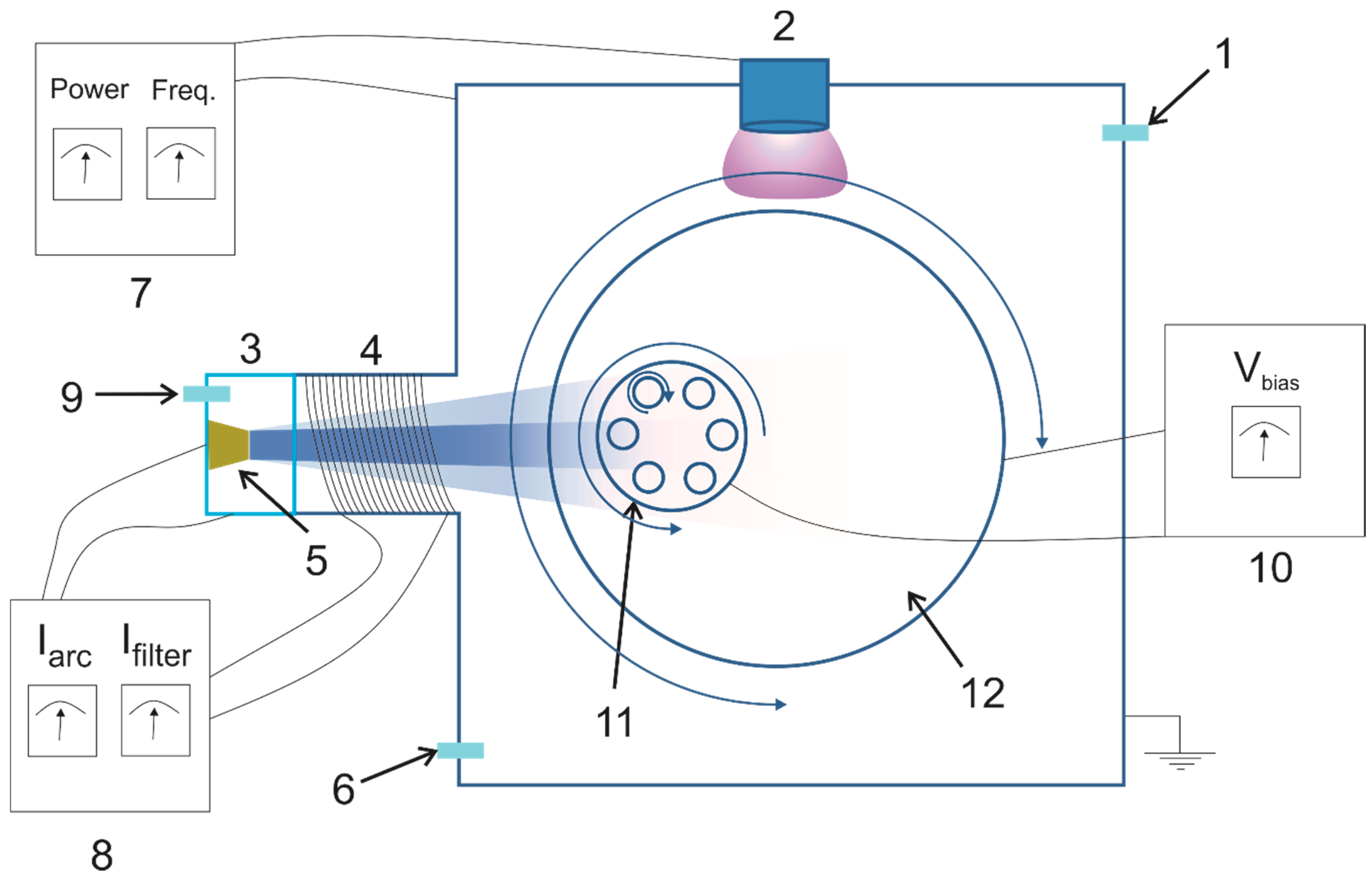
2.1. Deposition Parameters

Kennametal EDCT milling inserts (KC410M grade, Kennametal Widia Produktions GmbH, Essen, Germany) and Widia SNUN120408 (Kennametal Widia Produktions GmbH, Essen, Germany) turning inserts were used as the substrate material. The tools supplied by Kennametal to be used as substrates were as-received with 2 µm of titanium diboride (TiB2) deposited by DC magnetron sputtering using TiB2 ceramic tiles on a copper back plate.
The coatings were fabricated in a hybrid FVCA and magnetron sputtering PVD system described elsewhere [23]. The schematic of the specific system is shown in Figure 1. It comprises a cathodic arc source equipped with a cone-shaped cathode allowing up to 70 A arc current, a linear filter with adjustable magnetic coil (up to 10 A current), a magnetron sputtering source (ENI RPG-50, MKS, Crewe, UK) and a rotating substrate holder which can be biased (up to 650 V), and it can alternate between two PVD sources. Prior to deposition, the inserts were ultrasonically cleaned in an acetone bath for 15 minutes and then rinsed in isopropyl alcohol. A rotating substrate holder was employed to ensure the uniformity of the deposited coatings. Prior to each coating deposition, the system base pressure was below 3 × 10⁻⁶ Torr.

2.1.1. Monolayer DLC Coatings

FVCA was used to deposit DLC films from a cone-shaped graphite cathode supplied by Plasmatechnology (67 mm × 50 mm and 50 mm height). The argon pressure during the deposition was 4.5 × 10⁻³ Torr. A linear filter was used at the exit on the cathodic arc anode. To minimise the macroparticle content in the resulting thin films, the filter magnetic coil current was set to maximum 10 A. Based on previous studies, arc currents during deposition were at 40 A to prevent cathode fracture.
Five sets of coatings were deposited with the substrate bias varied to confirm it has an influence on the DLC coating wear resistance [15]. To avoid substrate overheating (above 200 °C) that would decrease sp3 content [24], the maximum deposition times (until the substrate reached 200 °C) were limited based on previous studies.

2.1.2. Multilayer DLC-WS2 Coatings

A hybrid FCVA-MS system enabled DLC-WS2 multilayer deposition. Each source was switched on sequentially for specific layer deposition. A rotating table allowed the substrate holder to move between the two sources. To investigate the influence of the number of DLC-WS2 layers on the cutting tool performance during machining trials, the target total thickness of the coatings was fixed at 500 nm. Deposition parameters (pressure, arc and filtering currents) for DLC layers were kept the same as for the monolayers with the substrate bias set to −100 V. WS2 was deposited from a 3-inch diameter target using pulsed DC magnetron sputtering with 80 W power and 100 kHz frequency to avoid arcing. Five sets of samples were deposited—monolayer WS2 and 2, 6, 12 and 24 layers of DLC-WS2 in total. Depending on the number of layers, the deposition time of certain layers was varied, though total time was the same—36 min—and volume fraction was always 50% DLC to 50% WS2.

2.2. Aluminium Milling Performance and Characterisation Tests

The tool cutting lifetime was studied by conducting face-milling experiments, carried out in an Okuma Cadet Mate CNC vertical machining centre. The DLC- and DLC-WS2-coated mill inserts were used to cut an AlSi alloy material. The performance of these coatings was benchmarked to a commercial TiB2-coated insert. The full cutting conditions are presented in Table 1. The tool wear during the cutting process was measured by an optical toolmaker microscope (Mitutoyo model TM) and recorded between passes.
Tescan dual-beam focused ion beam (FIB) scanning electron microscopy (SEM) was employed to study the cross section of the coatings as well as worn inserts and chips collected during the machining. The amount of machined material (Al) adherent to the tool was evaluated using the energy-dispersive X-ray spectroscopy (EDX) mode of SEM (20 kV). Alicona microscope 3D images were employed to determine the wear of the inserts, calculate roughness of the chips and precisely measure the tool edge geometry to compare with an unworn insert.
The CoF was measured using a Teer ST-3001 Tribo Tester. In this test, an indenter is drawn over a specimen surface with a constant or a linearly increasing load, until well-defined failure occurs at critical load Lc [25]. The normal force (Fz) and tangential force (Fx) are recorded. The CoF was measured using a bi-directional test with a fixed WC 5-mm-diameter ball, applying a constant 5 N load on a 10 mm distance for 100 cycles. An additional test with ramped load allowed for analysing the response of the multilayer coating under a variety of loads; an increasing progressive load was applied from 5 to 100 N, at a loading rate of 50 N/min and a linear velocity equal to 5 mm/min. The test outcomes include both CoF and wear characteristics—that is, adhesion and coating cracking. A series of images for each scratch trace were collected using an Olympus Lux optical microscope with 20× magnification. The images were later stitched using Microsoft Image Composite Editor. A Dektak stylus profilometer measured the profile of the scratches from Tribo Tester wear tests of the coatings.

3. Results and Discussion

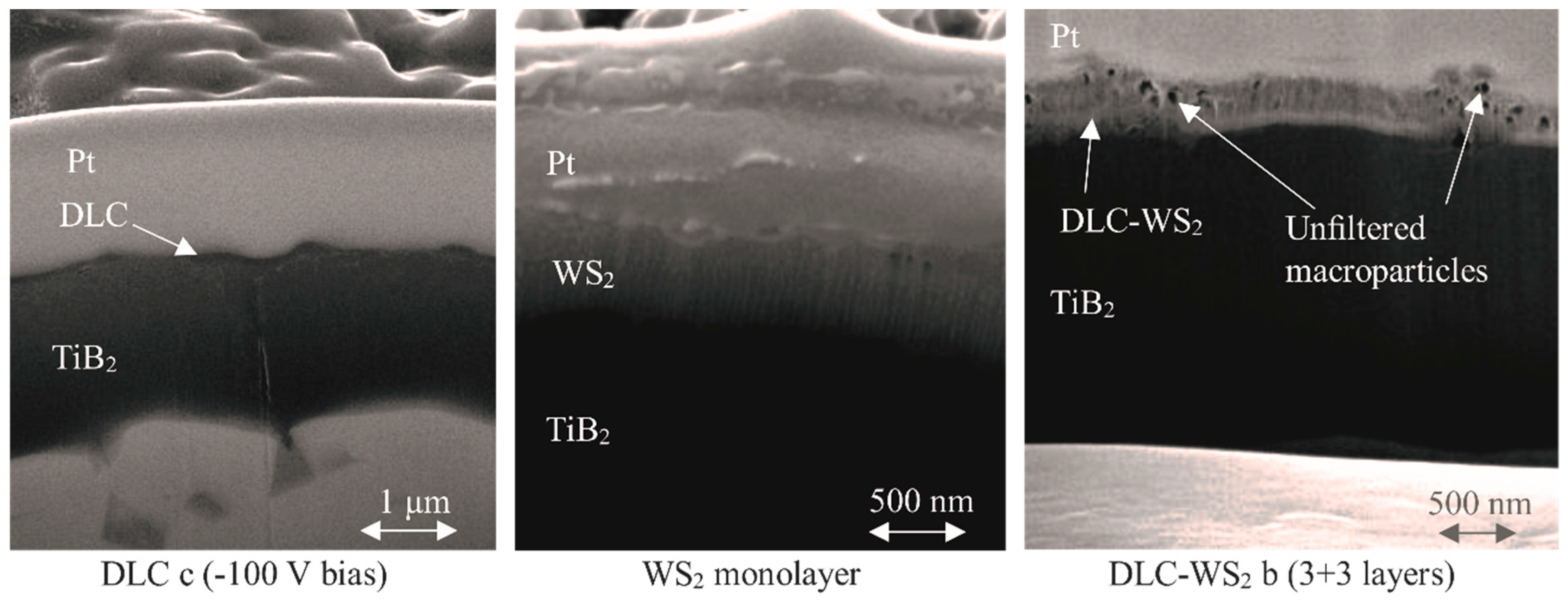
3.1. Coating Structure and Composition

The cross-sectional images of the coatings prepared using FIB are presented in Figure 2, and the summary of the main properties of the coatings are presented in Table 2 and Table 3. The deposited DLC coatings are not uniform—the thickness across the sample varies. As the filter used during the deposition was linear, it allowed some of the macroparticles to reach the substrate [26]. Thus they are found as a local increase in the thickness of the coating which influences the average film thickness measured for each of the biases. For the coatings deposited from −50 to 125 V the thickness is in the range 70–100 nm. The coating deposited with −200 V has a significantly lower thickness equal to 45 nm, which results from shorter deposition time rather than from the bias voltage itself. The WS2 monolayer, by contrast, is seen to have a uniform thickness and a columnar microstructure similar to that observed by other researchers [21,22]. The images of DLC-WS2 coatings do not allow us to distinguish separate layers, although the DLC macroparticles can be noticed. The combination of energetic deposition by FVCA and magnetron sputtering resulted in the DLC layers being doped into the structure rather than combined into the multilayer. This can have a positive effect on the hardness of the coatings, as Yang et al. [22] suggested that destroying the columnar morphology of WS2 can improve the adhesion and hardness, leading to better wear resistance. Nevertheless, while the total deposition time was the same for all of the DLC-WS2 coatings, the total thickness varies and is the lowest for the highest number of layers. The most probable reason is re-sputtering of WS2 caused by bombardment of energetic particles—mostly highly charged ions depositing DLC coating [21].

3.2. Coating Hardness

The results of the coating hardness measurement obtained using nanoindentation (average of 10 indents) are presented in Table 3. The hardness of around 2.4 GPa found for the WS2 monolayer is higher than the one measured by other researchers [22], although the measurements were done on Si and for 3 µm thick coating. With the addition of additional DLC layers, the hardness increases to 6.6 GPa for DLC-WS2 d, which suggests the positive effect of the interface strengthening [22].

3.3. Frictional Properties

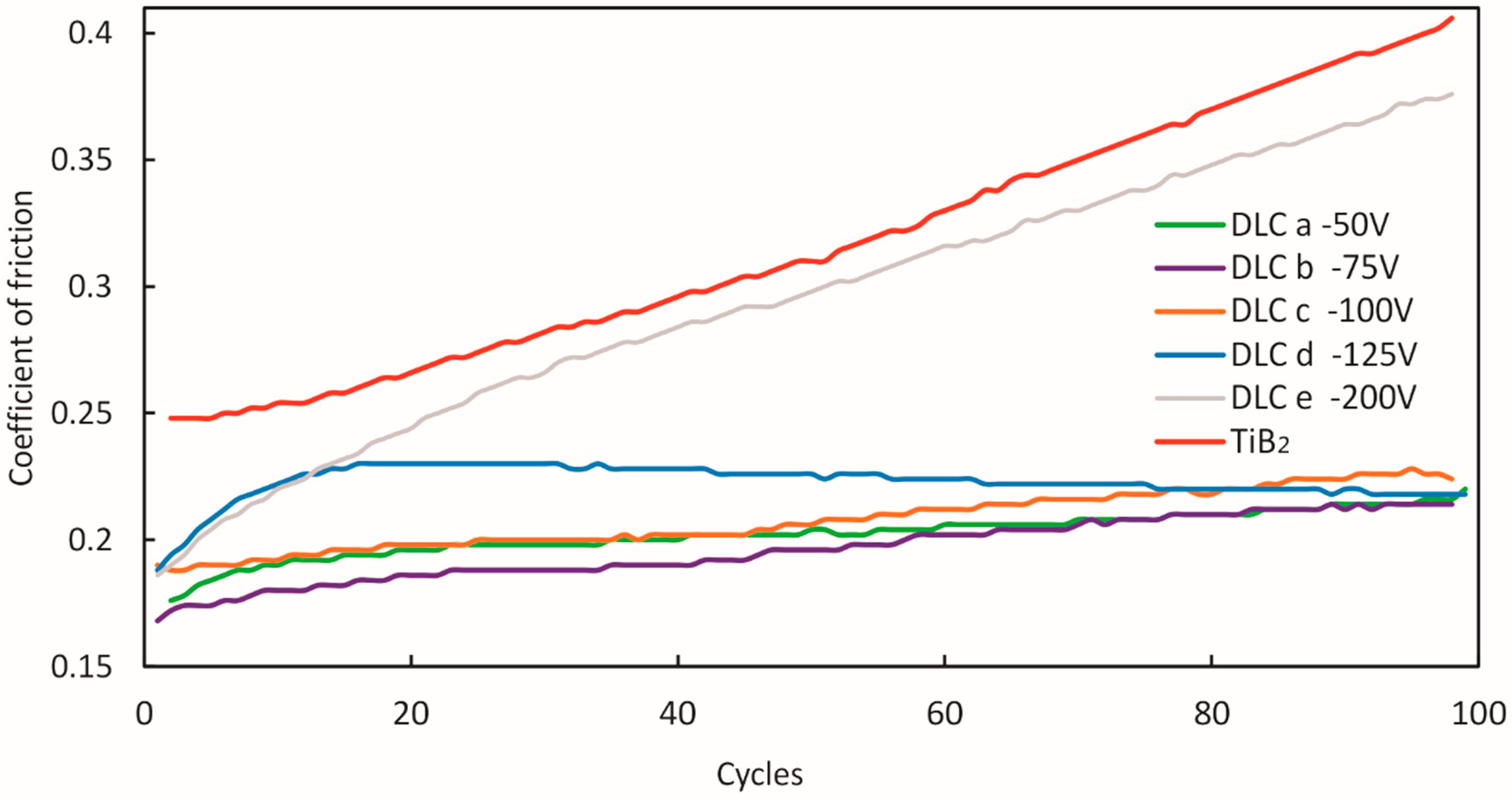
3.3.1. DLC Monolayers

Figure 3 shows the bi-directional scratch test results for five DLC-coated samples together with measurements for TiB2 as a function of a number of cycles. A CoF equal to 0.25 was measured for TiB2 for the first 16 cycles and then progressively increased to 0.4. Similar behavior has been observed by other researchers [27,28] during short-length (100 µm) wear tests. They observed that the running-in period lasted for around 3000 cycles, until a steady-state value of around 0.8 was achieved. Therefore, on the basis of previous research studies, we assume that the slow adaptation of TiB2 will extend the running-in stage of the coated tool during cutting. DLC coatings are known for their low CoFs, which are below 0.1 for ta-C [15]. It can be noticed that for most of the DLC coatings, the steady-state CoF is similar and is equal to 0.2. However, the adaptation of DLC d is quicker and occurs before the end of 20 cycles. For DLC e, on the other hand, although the initial CoF is the same, after 18 cycles its CoF follows the constant increase of TiB2. The friction of DLC coatings can be considered as the sum of adhesive, abrasive and shear mechanisms [29]. While adhesive friction is related to the coating microstructure, sliding environment and counterface, the abrasive contribution to DLC’s friction is related closely to the coating roughness [30]. DLC coatings are known for forming a transfer layer consisting of wear debris with low shear strength [10,29]. A transfer layer is typically composed of disordered carbon wear debris from the DLC coating, as well as wear debris from the counter face and from any reactive environmental species [30]. Therefore, this layer governs the friction in DLC coatings. As the thickness of DLC e was found to be below 50 nm, it may not have been enough to form such a transfer layer and affect CoF; as a result, the measured values are close to those of the TiB2 underneath.

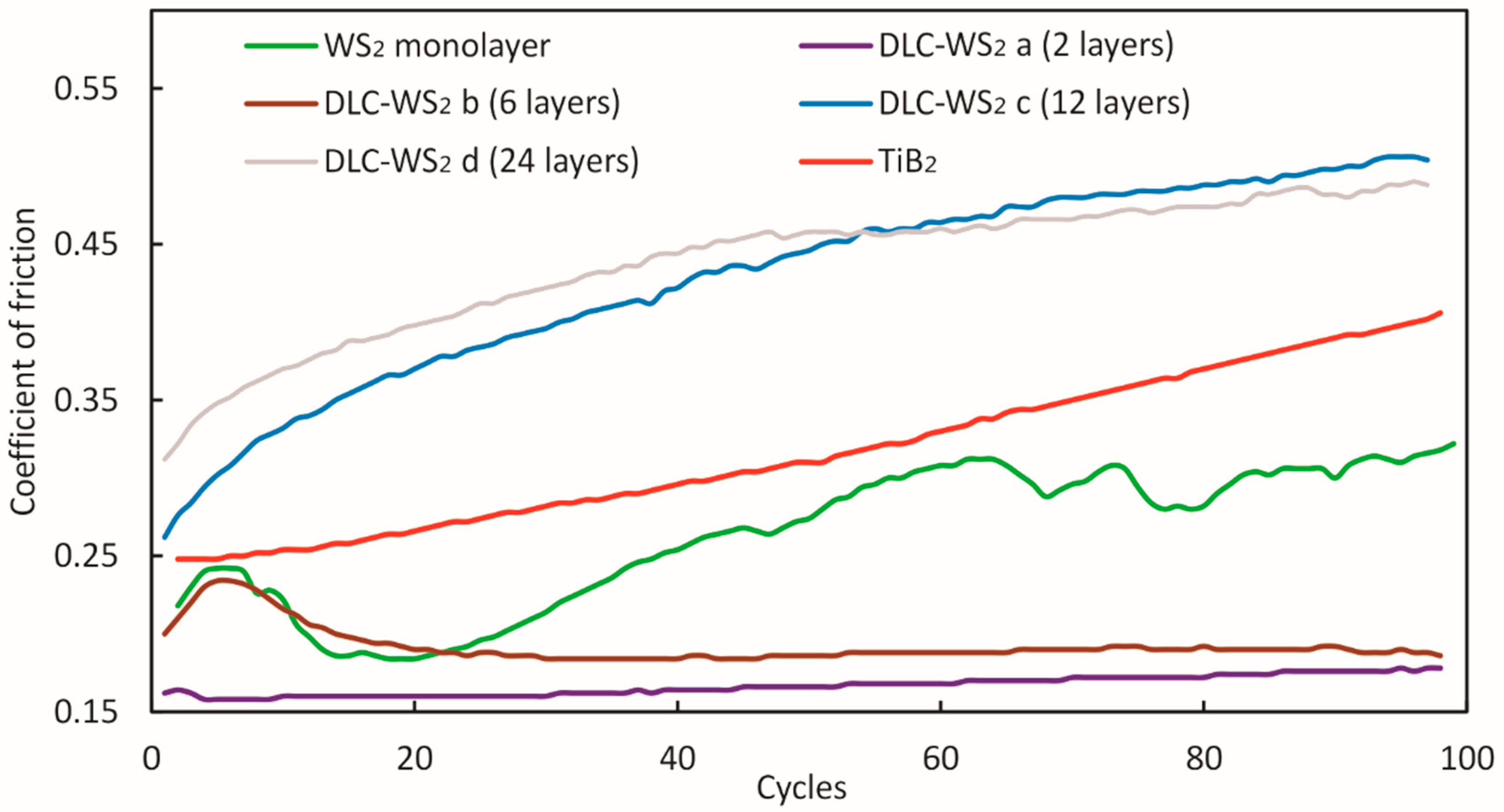
3.3.2. DLC-WS2 Multilayers

DLC-WS2 coatings deposited with different numbers of layers were tested during the wear test with a WC ball under a constant 5 N over 100 bi-directional cycles. The evolution of friction against number of cycles is presented in Figure 4. The progress of the CoF curve indicates that, due to the low hardness of WS2, it failed under the 5 N load. For the first 20 cycles, the friction actually decreased, as the coating that was being constantly removed piled up in front of the indenter, forming a low-friction transfer layer [25]. After between 45 and 50 cycles, the WS2 was completely worn; therefore, the CoF matched that of the initial TiB2 − 0.25.
SEM images of the wear tracks (Figure 5) indicate that coating spallation occurred, which can be noticed on the sides of the track. The EDX analysis and scratch profiles obtained using profilometer confirmed almost complete wear of the coating, as little WS2 can be recognised on the track.
The introduction of an additional DLC layer on top of WS2 (sample DLC-WS2 a) to form a bilayer had a significant impact on the frictional properties of the coating system. The CoF measured was low (0.15) and did not significantly change with the number of cycles. Hard DLC serves as a protective layer, while WS2 provides lubrication. Good tribological performance is confirmed on the SEM image in Figure 5; the track width is narrower than for WS2 monolayer, no coating spallation can be observed and EDX compositional analysis confirms the presence of WS2 in the track. The rapid adaptation of this coating should significantly improve cutting performance when applied to the tool, which would be evident especially during the running-in stage of the machining. Increasing the number of layers to 6 (DLC-WS2 b) led to an increase in the time of indenter-coating system adaptation; however, after 100 cycles a CoF similar to that of DLC-WS2 a was measured. However, for DLC-WS2 coatings having the highest number of layers (12 and 24), progressive increase of the CoF was recorded up to the value 0.5, indicating the rapid failure of these coatings. Introducing a high number of layers can prevent crack propagation by stopping it on the interfaces between layers; however, it can also increase the intrinsic stress in the coating [31], moving their failure mode from ductile into brittle [25], which could be observed for DLC-WS2 c and d.
A ramped scratch load test can analyse the response of the coating to a variety of loads, giving information about the friction, wear characteristics and microcracking [4]. Figure 6 presents the evolution of CoF between the coating material and WC ball for a progressive load of 5–100 N applied over a 10 mm distance. The CoF for WS2 monolayer and the DLC-WS2 a bilayer progressively decreased as the load and scratch distance increased. As the direction of the scratch was constant, the small portions of the worn coating constantly accumulated in front of the ball, forming a low-friction lubricious layer that can be noticed in the optical image of the WS2-coated sample scratch in Figure 7. The base material (TiB2 coating) can be observed only at the end of the scratch. For the maximum load, the CoF for WS2 monolayer was as low as 0.05, which matches the findings made by other researchers [8,20,22]. The DLC-WS2 bilayer ensured a very low CoF of around 0.07, which together with previous results from a bi-directional fracture test and with no evidence of any coating spallation or delamination over the whole 10–100 N range of loads (Figure 7), confirms its good adhesion and lubricious properties. By contrast, DLC-WS2 d, with 24 layers, shows clear signs of coating spallation, which can be recognised by peaks on the CoF graph and exposure of the material underneath visible in the optical image in Figure 7. At around 57 N load, the coating is completely worn, the coefficient of friction rapidly increases, and the material underneath is exposed for the whole width of the scratch. In comparison, the DLC c monolayer spalls at around 40 N load.

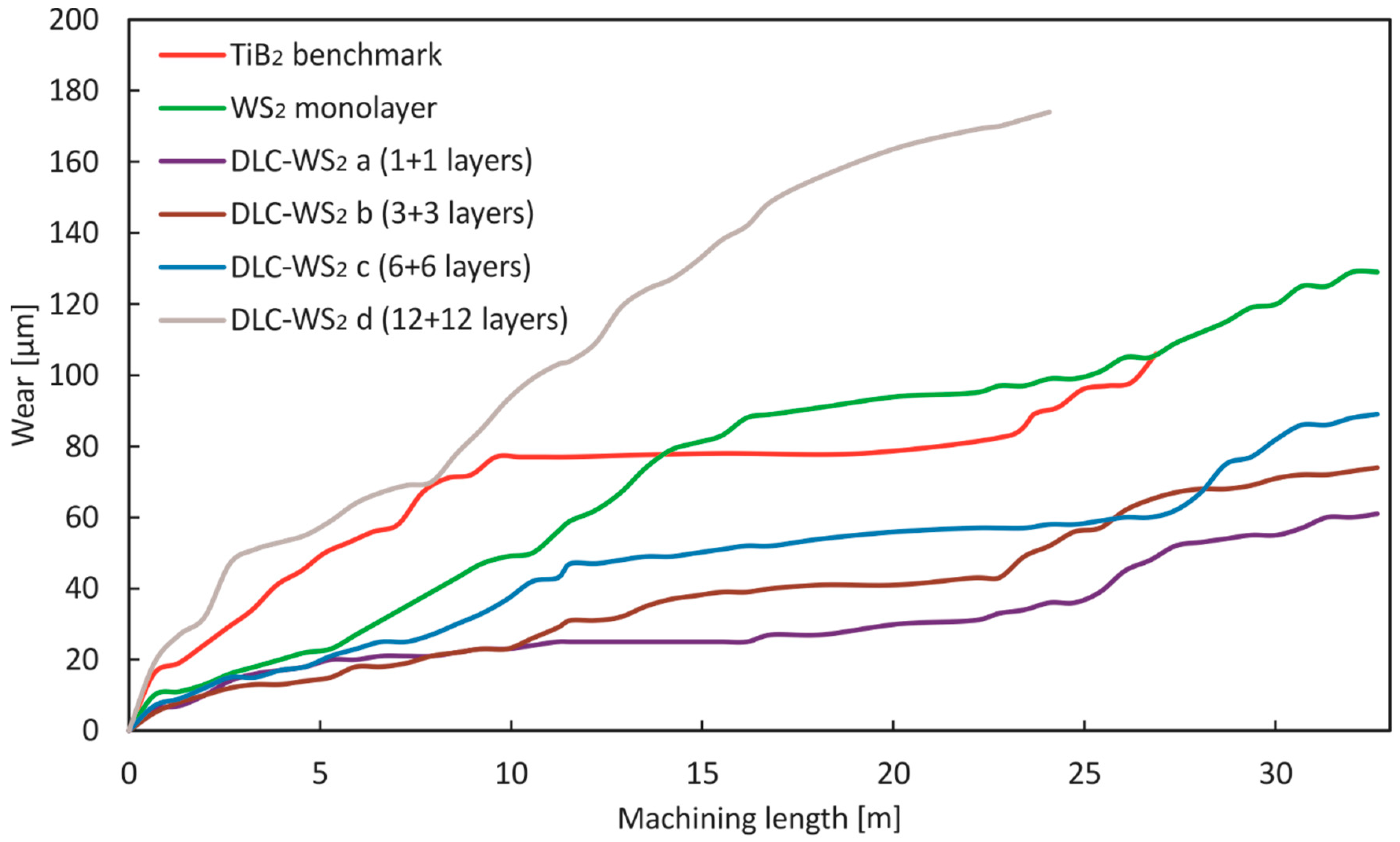
3.4. Machining Studies

Typically, the wear process consists of three stages: the running-in stage, the steady-state stage and the surface damage stage. In the initial and final stages, the surface damage of the tool can be observed, while during the steady-state stage, stable wear and friction conditions are typically achieved and, therefore, little or no macroscopic damage of the surface is visible [1]. The main goal of tool tribology is to increase the time during which the tool is in steady-state and thus decrease tool wear and reduce the CoF. These improvements eventually will lead to tool-life enhancement and improved workpiece quality (surface finish and dimensional accuracy) [1,32].

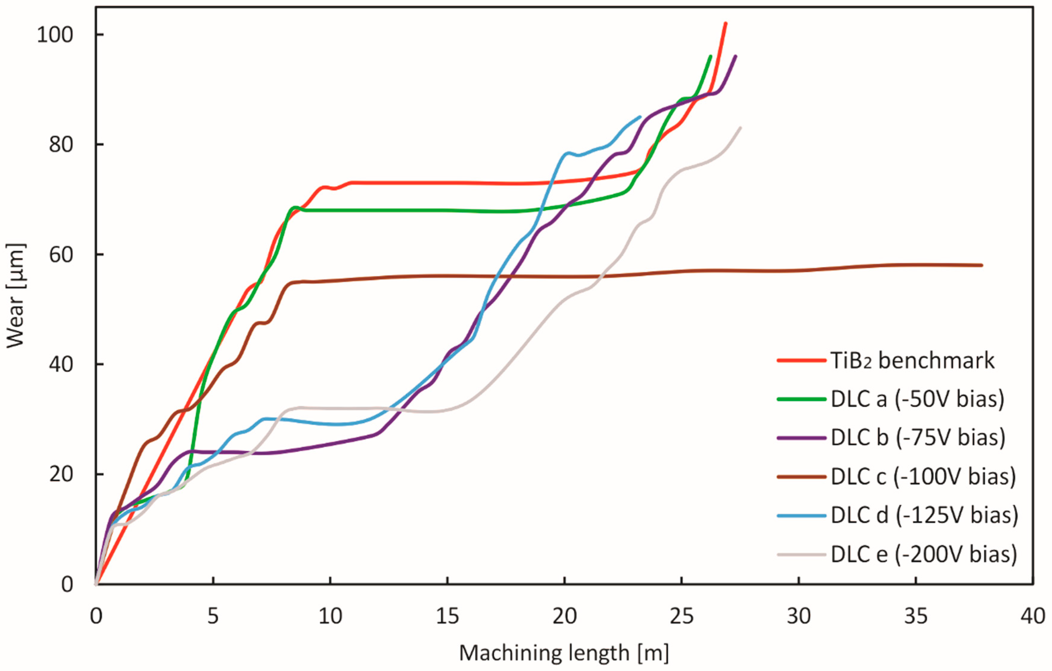
3.4.1. DLC Monolayer

Figure 8 shows the change in flank wear of DLC- and TiB2-coated tools with respect to the cutting length during AlSi milling. TiB2 presents a typical wear curve with a running-in stage for the first 10 m, then a stable state up to 24 m, after which catastrophic failure occurs leading to elevated tool wear. All of the DLC coatings outperform the benchmark TiB2 coating. For DLC a, the wear curve follows the TiB2 curve, with a small decrease in tool wear in the steady state. However, while coatings on samples DLC b, d and e significantly decreased the wear during the running-in stage, only DLC b also limited the machining length needed to achieve steady-state, thereby improving the surface finish of the machined parts [33]. Nevertheless, the width of the stable wear is overall shorter than it is for the TiB2-coated tool. For DLC c, on the contrary, which was deposited with −100 V, the wear in the first stage decreased compared to TiB2. Moreover, the steady-state stage continues up to 38 m of machining length, giving 85% improvement compared with TiB2 and other DLC coatings. This DLC coating is found to ensure the best protection on the microlever during the running-in stage when the geometrical adaptation of the cutting edge happens [1]. This can be attributed to high sp3 content expected for −100 V biased samples according to the work of Konkhunthot et al. [11] who based on Ramman and XPS analysis concluded 83% of sp3 bonds in the DLC coatings deposited by FVCA with −100 V bias. Sp3 bonds provide both high hardness of the films and low CoF [34]. When the steady state is achieved, the TiB2 coating underneath can protect the tool material, and thereby the tool life is significantly improved.

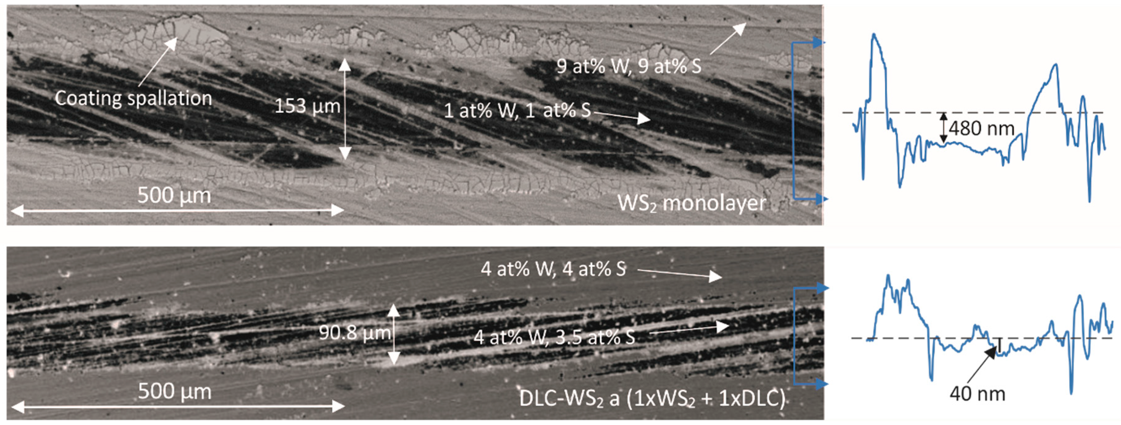
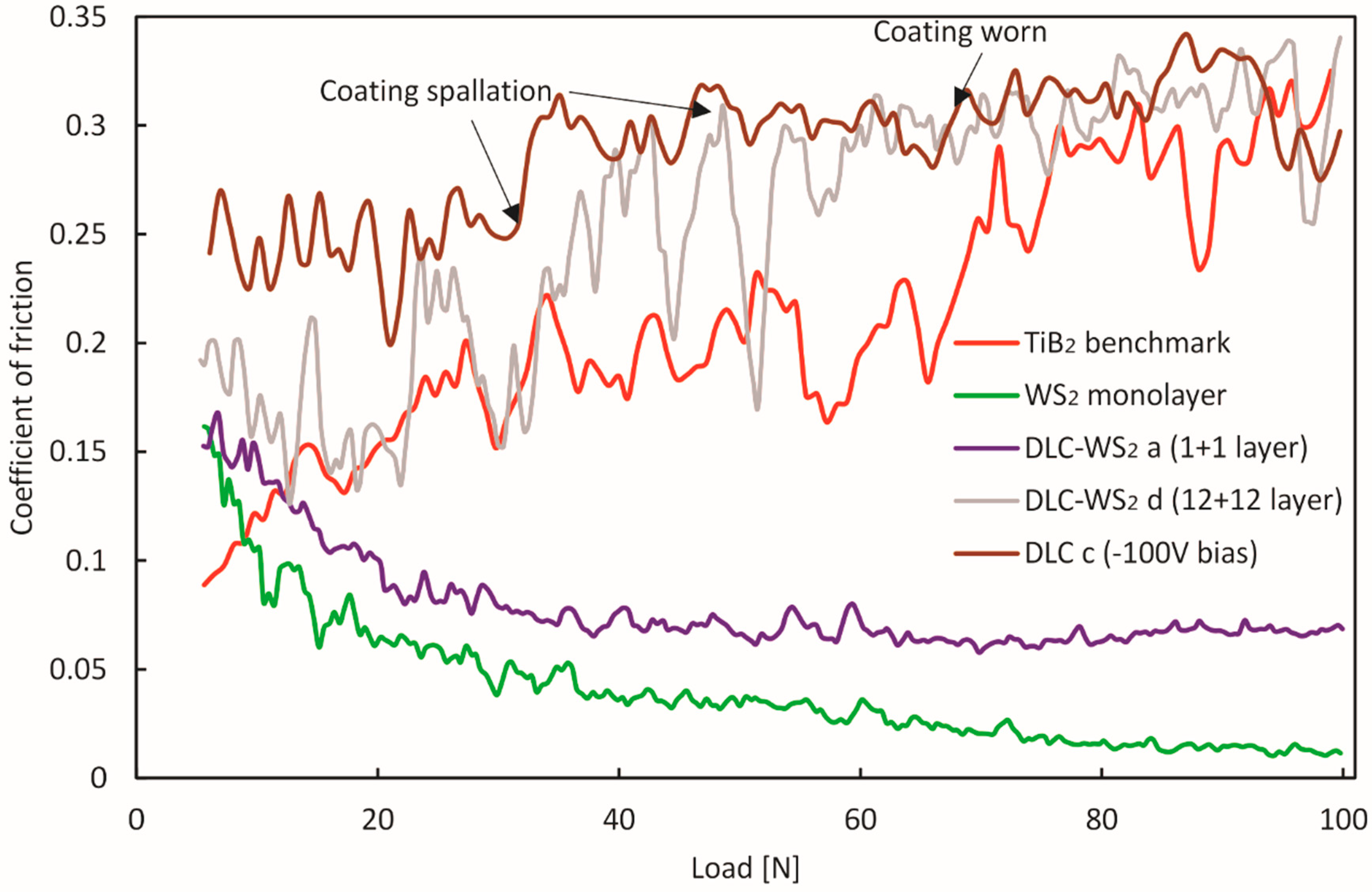
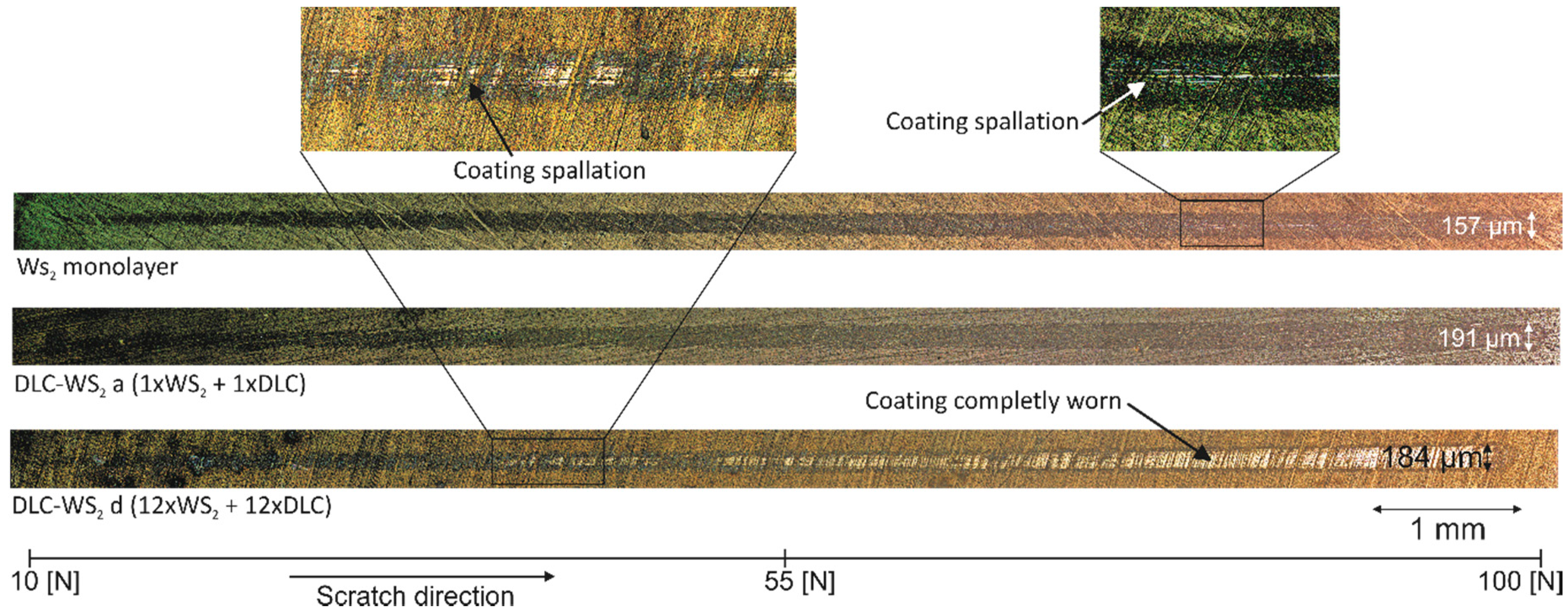
3.4.2. DLC-WS2 Multilayers

The changes in flank wear with respect to the cutting length are presented in Figure 9. The wear curve of the WS2 monolayer confirms the observations made during the bi-directional fracture test: for the first 12 m of machining, the WS2 serves as a source of lubrication, therefore, the tool wear is lower compared to TiB2, and the running-in stage is longer. However, once the WS2 coating wears out, the tool wear increases and typical steady state with little wear cannot be observed. Instead, a flat part of the curve can be noticed between 16 and 24 m, after which the rate of the tool fracture grows. Similarly, DLC-WS2 d does not present a steady state but rather constant rapid wear. Possibly, as suggested in Section 3.3.2, a large number of layers (24 in total) and microparticles generate high stress in the coating, causing its instant failure, with greater wear at the very beginning of the cutting process. As a result of the rapid wear, the cutting forces increase and lead to elevated wear of the tool. On the other hand, DLC-WS2 a, b and c all outperform both TiB2 and monolayer DLC coatings. Interestingly, only DLC-WS2 c, which combines 12 layers in total, presents the typical three-stage wear curve with sharp changes between the stages. It is noticeable that the machining length was extended up to 28 m as compared to TiB2. In the case of the 2- and 6-layer coatings, the transition between the running-in stage and the steady state is not as pronounced as a TiB2 benchmark sample. The DLC-WS2 a curve in particular, flattens after just 5 m of machining, which indicates this multilayer combination of DLC with WS2 ensures rapid adaptation of the tool at the very beginning of the cutting process, thereby limiting the initial wear. In spite of this, the total machining length was not extended, and the tool wear is just 25% that of the TiB2. A rapid adaptation of the tool is essential, especially during finish machining, when surface finish and dimensional accuracy are important.

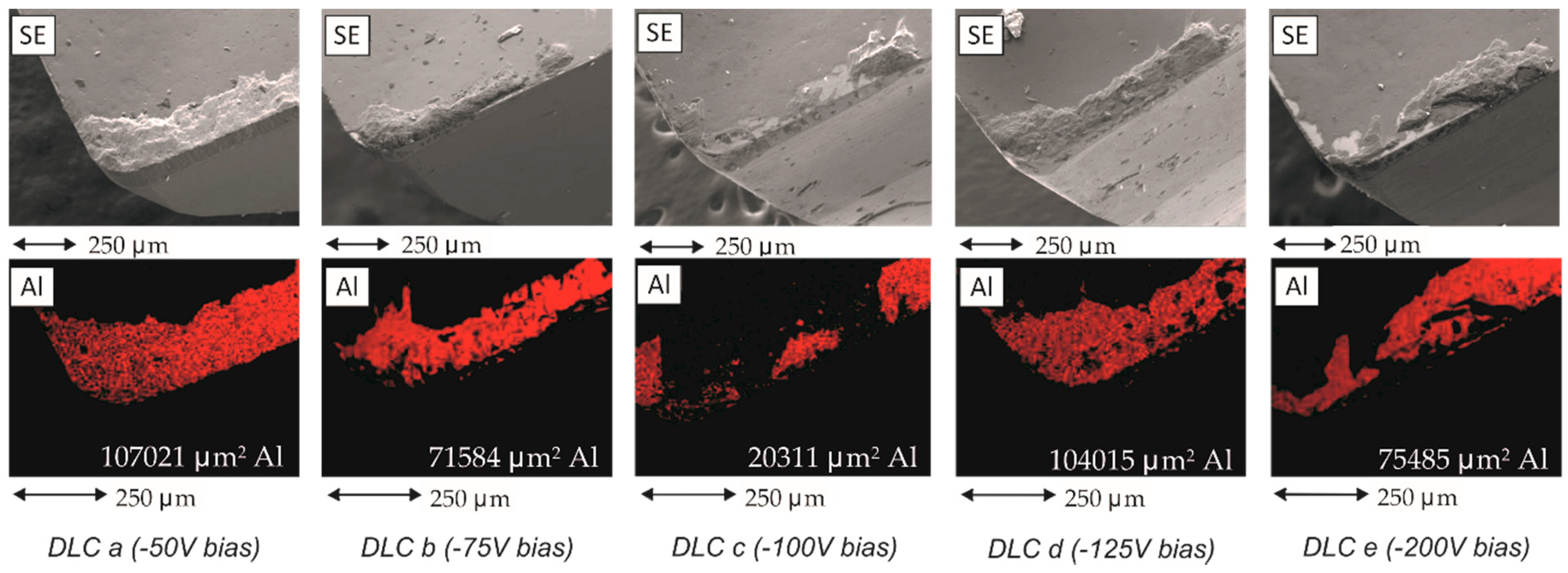
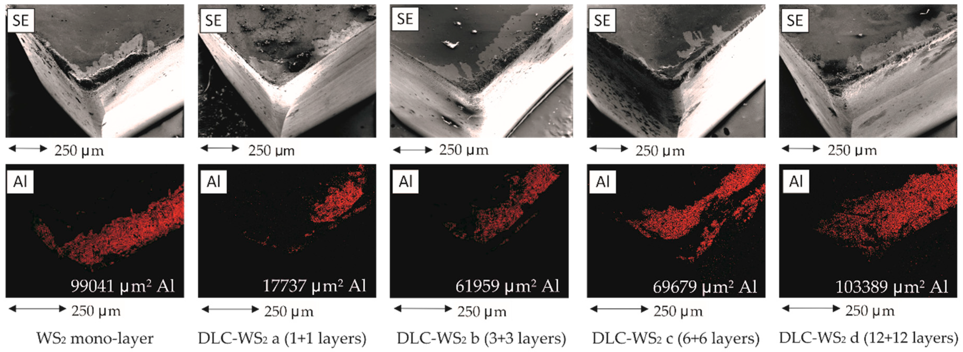
3.5. EDX Element Mapping

The amount of aluminium that adheres to the cutting edge was assessed using EDX element mapping. The Image J software allowed calculation of the area covered by the adherent material. SEM images using secondary electrons allowed determination of tool wear.

3.5.1. DLC Monolayer

Figure 10 presents the SEM micrographs along with EDX elemental analysis Al dot maps of the rake surfaces of the DLC-coated milling inserts after machining of Al-10Si. Aluminium adhering to the rake edge can be observed in all the samples, however, its shape and amount differ, which is more visible on the SEM images.
Significant Al sticking can be observed for samples DLC a and DLC d. The adherent layer is thick and uniform across the edge, which indicates that after a certain machining length and elevated tool wear, this DLC coating failed and continuous build-up of material occurred. For samples b and e, on the other hand, despite the Al sticking, it can be observed especially on SEM images that Al splats and thin layers are formed rather than large uniform Al build-ups. The amount of Al adhered is lower than for the DLC a and d. Especially for DLC b, it is located at the very edge of the tool, confirming slightly better performance during the matching test (Figure 8). This indicates better protection against aluminium sticking provided by these coatings, as the Al build-up could partially detach from the tool surface even at the very end of the machining process.
Even though the machining length was longer for sample DLC c, the smallest Al build-up can be noticed. It forms only a thin layer close to the tool edge. The amount is only around 30% of that on the other coated tools, confirming that −100 V bias is optimum for producing thin DLC coating that facilitates tool adaptation during the running-in stage and prevents aluminium adhesion to the tool edge better than does the TiB2 coating. This matches the results obtained from machining tests and CoF measurements.

3.5.2. DLC-WS2 multilayers
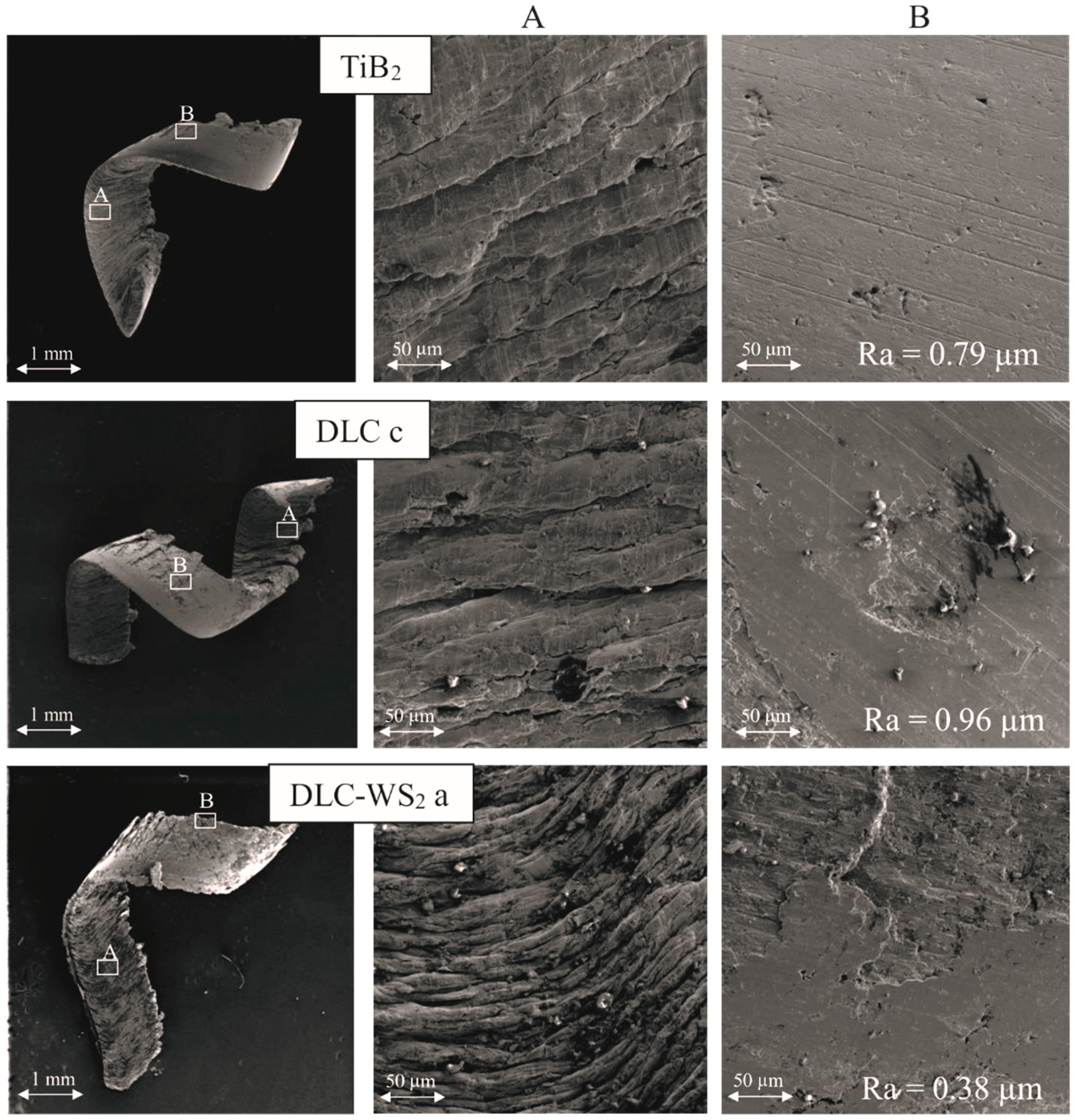
The Al elemental maps and SEM images of the rake faces of the milling inserts coated with the multilayer DLC-WS2 are presented in Figure 11. Except for the WS2 monolayer and DLC-WS2 d, it can be observed that the amount of the Al is lower than for DLC. A larger amount of Al adherent can be noticed for the WS2 monolayer, confirming the degradation of its tribological properties in the wet environment [21] and rapid wear caused by hard AlSi alloy. For DLC-WS2 c and d, crater and abrasive flank wear occurred. This indicates that a build-up edge occurred, leading to microcrack formation. As a consequence of the cyclical stress, separation of the grains from the surface of the tool occurred, which is a typical consequence of the adhesive interaction of tungsten carbide grains with the machined material [1,35]. A thin layer of Al adhered on the rake face can also be noticed beside the build-up at the very flank edge of the tool coated with DLC-WS2 c.
The lack of crater wear on sample DLC-WS2 a and only slight Al adherent in the form of a thin layer indicates that adding DLC into the WS2 film can significantly increase tool lifetime [20]. The WS2 provides good lubrication of the tool-chip area, while DLC adds wear resistance and prevents oxidation of the WS2 lamellas [22].
Increasing the number of layers while maintaining the same volume fraction of DLC and WS2 could prevent crack propagation and increase the failure resistance of the coating [36]. Even though such an attempt was successful for fabrication of WSx/a-C coatings using magnetron sputtering [22], in this study applying a deposition method as energetic as cathodic arc combined with pulsed DC magnetron sputtering for multilayer deposition may have introduced too much stress into the coating. As a result, the best tribological performance was achieved for monolayers of DLC and WS2 combined into a bilayer structure.

3.6. Chip Formation

Figure 12 shows the chip material removed during the running-in stage, and the chip surfaces after Al-10Si milling using tools coated with TiB2, DLC and DLC-WS2 coatings, respectively. To confirm the hypothesis that DLC-WS2 provides better lubrication of the tool-chip area than the DLC coating, the roughness of the chips from machining with TiB2, DLC C and DLC-WS2 a was measured using the Alicona 3D digital microscope. As all of the chips were collected at the running-in stage when the coatings had not worn, the sizes of all of the chips are similar. In appearance, TiB2 chips look smoother, indicating this particular coating ensured lubrication and limited Al sticking, thus chip flow could be smooth resulting in a smoother surface under the produced chips [10]. The results indicated that Ra for TiB2 and DLC chips was 0.79 and 0.96 µm, respectively. The higher roughness of chips from machining using DLC-coated tools confirms the observation made during the scratch test in Figure 3. Nonhydrogenated amorphous carbon films typically have higher CoF than ones containing hydrogen [15]. However, their high hardness and anti-adherent properties [1] make them perfect for Al alloy machining. Therefore, the tool lifetime was improved in Figure 8.
Contrary to the roughness of the chips from cutting with DLC-WS2, a coated mill has Ra = 0.38 µm. Friction-reduction and increased wear-resistance can be attributed to the formation of a transfer lubricant layer of WS at the tool-chip interface during the cutting process [20]. The low roughness of the chips indicates not only improved tool longevity (Figure 12) but also a better surface finish on the machined material.

4. Conclusions

A hybrid cathodic arc—magnetron sputtering system was successfully used to deposit nonhydrogenated thin DLC films and DLC-WS2 multilayers on TiB2 precoated (KC410 grade) milling inserts. The volume fraction of each multilayered coating was maintained while the number of layers was varied. The substrate bias during the DLC deposition was found to have a significant influence on the cutting performance of the tools. All of the coatings decreased the tool wear compared to TiB2-only coatings. However, it was found that a coating produced at −100 V bias could improve machining length by 80%. The post-machining tool investigation using an SEM microscope and EDX elemental mapping also revealed that in addition to improved machining length also Al adherence to the tool was limited, as only a very low Al build-up was found. Combining the DLC deposited at -100 V with WS2 resulted in improved frictional performance, as a CoF below 0.2 was recorded for bilayer DLC-WS2 during the scratch test. While a low friction coefficient was measured for monolayer WS2 (0.25), its low hardness did not allow it to decrease tool wear during the machining process. By contrast, a significant influence on tool wear was observed for 2, 6 and 12 layers of DLC-WS2. The best performance was found for a two-layer coating which shortened the running-in stage to just 5 m and lowered the tool wear in the stable state four-fold compared to the TiB2-coated tool. Friction reduction and increased wear resistance can be attributed to the formation of a transfer lubricant layer at the tool-chip interface during the cutting process, as is typical for solid lubricants’ coatings.

Author Contributions

Methodology, G.S.F.-R.; investigation, T.L.B. and J.M.P.; resources, J.K. and S.C.V.; writing—original draft preparation, T.L.B.; writing—review and editing, J.R.; visualization, T.L.B.; supervision, J.L.E.; project administration, J.L.E.; funding acquisition, J.K.

Funding

This research was partially funded by Kennametal Gmbh.

Conflicts of Interest

The authors declare no conflict of interest.

References

  1. German Fox-Rabinovich, G.E.T. Self-Organization During Friction: Advanced Surface-Engineered Materials and Systems Design; CRC Taylor & Francis: Boca Raton, FL, USA, 2013; Volume 53, ISBN 9788578110796. [Google Scholar]
  2. Jesudass Thomas, S.; Kalaichelvan, K. Comparative study of the effect of surface texturing on cutting tool in dry cutting. Mater. Manuf. Process. 2018, 33, 683–694. [Google Scholar] [CrossRef]
  3. Schaefer, A.; Reichenbach, M.; Fey, D. IAENG Transactions on Engineering Technologies; Springer: Dordrecht, The Netherlands, 2013; Volume 170, ISBN 978-94-007-4785-2. [Google Scholar]
  4. Chowdhury, M.S.I.; Chowdhury, S.; Yamamoto, K.; Beake, B.D.; Bose, B.; El, A.; Cavelli, D.; Dosbaeva, G.; Aramesh, M.; Fox-rabinovich, G.S.; et al. Wear behaviour of coated carbide tools during machining of Ti6Al4V aerospace alloy associated with strong built up edge formation. Surf. Coat. Technol. 2017, 313, 319–327. [Google Scholar] [CrossRef]
  5. Rao, J.; Cruz, R.; Lawson, K.J.; Nicholls, J.R. Carbon and titanium diboride (TiB2) multilayer coatings. Diam. Relat. Mater. 2004, 13, 2221–2225. [Google Scholar] [CrossRef]
  6. Rivero, A.; Aramendi, G.; Herranz, S.; De Lacalle, L.N.L. An experimental investigation of the effect of coatings and cutting parameters on the dry drilling performance of aluminium alloys. Int. J. Adv. Manuf. Technol. 2006, 28, 1–11. [Google Scholar] [CrossRef]
  7. Kishawy, H.A.; Dumitrescu, M.; Ng, E.G.; Elbestawi, M.A. Effect of coolant strategy on tool performance, chip morphology and surface quality during high-speed machining of A356 aluminum alloy. Int. J. Mach. Tools Manuf. 2005, 45, 219–227. [Google Scholar] [CrossRef]
  8. Zhu, L.; Wang, C.; Wang, H.; Xu, B.; Zhuang, D.; Liu, J.; Li, G. Microstructure and tribological properties of WS2/MoS2 multilayer films. Appl. Surf. Sci. 2012, 258, 1944–1948. [Google Scholar]
  9. Schultrich, B.; Scheibe, H.-J.; Drescher, D.; Ziegele, H. Deposition of superhard amorphous carbon films by pulsed vacuum arc deposition. Surf. Coat. Technol. 1998, 98, 1097–1101. [Google Scholar] [CrossRef]
  10. Fukui, H.; Okida, J.; Omori, N.; Moriguchi, H.; Tsuda, K. Cutting performance of DLC coated tools in dry machining aluminum alloys. Surf. Coat. Technol. 2004, 187, 70–76. [Google Scholar] [CrossRef]
  11. Konkhunthot, N.; Euaruksakul, C.; Photongkam, P.; Wongpanya, P. Characterization of Diamond-like Carbon (DLC) Films Deposited by Filtered Cathodic Vacuum arc Technique. J. Met. Mater. Miner. 2013, 23, 35–40. [Google Scholar]
  12. Mattox, D.M. Handbook of Physical Vapor Deposition (PVD) Processing: Film Formation, Adhesion, Surface Preparation and Contamination Control; Noyes Publications: Westwood, NJ, USA, 1998; ISBN 0815514220. [Google Scholar]
  13. Tsai, P.-C.; Hwang, Y.-F.; Chiang, J.-Y.; Chen, W.-J. The effects of deposition parameters on the structure and properties of titanium-containing DLC films synthesized by cathodic arc plasma evaporation. Surf. Coat. Technol. 2008, 202, 5350–5355. [Google Scholar] [CrossRef]
  14. Reinke, S.; Kulisch, W. Mechanisms in ion-assisted deposition of superhard coatings: Cubic boron nitride–tetrahedral amorphous carbon. Surf. Coat. Technol. 1997, 97, 23–32. [Google Scholar] [CrossRef]
  15. Robertson, J. Diamond-like amorphous carbon. Mater. Sci. Eng. R Rep. 2002, 37, 129–281. [Google Scholar] [CrossRef]
  16. Fallon, P.J.; Veerasamy, V.S.; Davis, C.A.; Robertson, J.; Amaratunga, G.A.J.; Milne, W.I.; Koskinen, J. Properties of filtered-ion-beam-deposited diamondlike carbon as a function of ion energy. Phys. Rev. B 1993, 48, 4777–4782. [Google Scholar] [CrossRef]
  17. Koçak, Y.; Akaltun, Y.; Gür, E. Magnetron sputtered WS2; Optical and structural analysis. J. Phys. Conf. Ser. 2016, 707. [Google Scholar] [CrossRef]
  18. Banerjee, T.; Chattopadhyay, A.K. Structural, mechanical and tribological properties of pulsed DC magnetron sputtered TiN–WSx/TiN bilayer coating. Surf. Coat. Technol. 2015, 282, 24–35. [Google Scholar] [CrossRef]
  19. Clauss, F.J. Solid Lubricants and Self-Lubricating Solids; Academic Press: New York, NY, USA, 1972. [Google Scholar]
  20. Banerjee, T.; Chattopadhyay, A.K. Structural, mechanical and tribological properties of WS2-Ti composite coating with and without hard under layer of TiN. Surf. Coat. Technol. 2014, 258, 849–860. [Google Scholar] [CrossRef]
  21. Särhammar, E.; Strandberg, E.; Sundberg, J.; Nyberg, H.; Kubart, T.; Jacobson, S.; Jansson, U.; Nyberg, T. Mechanisms for compositional variations of coatings sputtered from a WS2 target. Surf. Coat. Technol. 2014, 252, 186–190. [Google Scholar] [CrossRef]
  22. Yang, F.; Lu, Y.; Zhang, R.; Zhang, X.; Zheng, X. Microstructure and tribological properties of WSx/a-C multilayer films with various layer thickness ratios in different environments. Surf. Coat. Technol. 2017, 309, 187–194. [Google Scholar] [CrossRef]
  23. Brzezinka, T.; Rao, J.; Chowdhury, M.; Kohlscheen, J.; Fox Rabinovich, G.; Veldhuis, S.; Endrino, J. Hybrid Ti-MoS2 Coatings for Dry Machining of Aluminium Alloys. Coatings 2017, 7, 149. [Google Scholar] [CrossRef]
  24. Grill, A. Diamond-like carbon: State of the art. Diam. Relat. Mater. 1999, 8, 428–434. [Google Scholar] [CrossRef]
  25. Bull, S.J. Failure modes in scratch adhesion testing. Surf. Coat. Technol. 1991, 50, 25–32. [Google Scholar] [CrossRef]
  26. Anders, A. Cathodic Arcs Fom Fractal Spots to Energetic Condensation; Springer Inc.: New York, NY, USA, 2008; ISBN 9780387791074. [Google Scholar]
  27. Prakash, B.; Ftikos, C.; Celis, J.P. Fretting wear behavior of PVD TiB2 coatings. Surf. Coat. Technol. 2002, 154, 182–188. [Google Scholar] [CrossRef]
  28. Murthy, T.S.R.C.; Basu, B.; Srivastava, A.; Balasubramaniam, R.; Suri, A.K. Tribological properties of TiB2 and TiB2 - MoSi2 ceramic composites. J. Eur. Ceram. Soc. 2006, 26, 1293–1300. [Google Scholar] [CrossRef]
  29. Fontaine, J.; Donnet, C.; Erdemir, A. Fundamentals of the tribology of DLC coatings. Tribol. Diamond-Like Carbon Film. Fundam. Appl. 2008, 139–154. [Google Scholar] [CrossRef]
  30. Sutton, D.C.; Limbert, G.; Stewart, D.; Wood, R.J.K. The friction of diamond-like carbon coatings in a water environment. Friction 2013, 1, 210–221. [Google Scholar] [CrossRef]
  31. Guo, C.Q.; Pei, Z.L.; Fan, D.; Liu, R.D.; Gong, J.; Sun, C. Predicting multilayer film’s residual stress from its monolayers. Mater. Des. 2016, 110, 858–864. [Google Scholar] [CrossRef]
  32. List, G.; Nouari, M.; Géhin, D.; Gomez, S.; Manaud, J.P.; Le Petitcorps, Y.; Girot, F. Wear behaviour of cemented carbide tools in dry machining of aluminium alloy. Wear 2005, 259, 1177–1189. [Google Scholar] [CrossRef]
  33. Ramaswami, R. The effect of the built-up-edge(BUE) on the wear of cutting tools. Wear 1971, 18, 1–10. [Google Scholar] [CrossRef]
  34. Robertson, J. Properties of diamond-like carbon. Surf. Coat. Technol. 1992, 50, 185–203. [Google Scholar] [CrossRef]
  35. Heinrichs, J.; Olsson, M.; Jacobson, S. New understanding of the initiation of material transfer and transfer layer build-up in metal forming—In situ studies in the SEM. Wear 2012, 292–293, 61–73. [Google Scholar] [CrossRef]
  36. Vereschaka, A.A.; Grigoriev, S.N.; Vereschaka, A.S.; Popov, A.Y.; Batako, A.D. Nano-scale multilayered composite coatings for cutting tools operating under heavy cutting conditions. Procedia CIRP 2014, 14, 239–244. [Google Scholar] [CrossRef]
Figure 1. Schematic view of the deposition system (1—vacuum cryopump inlet, 2—3″WS2 sputtering target, 3—anode, 4—linear filter, 5—graphite cathode, 6—sputtering argon inlet, 7—PVD sputtering power unit, 8—cathodic arc power unit, 9—cathodic arc argon inlet, 10—substrate bias power unit, 11—rotating substrate holder, 12—substrate table).
Coatings 09 00192 g001
Figure 2. SEM images of coatings’ cross sections prepared using focused ion beam (FIB).
Coatings 09 00192 g002
Figure 3. Friction coefficient vs number of cycles for DLC coatings and reference TiB2-coated samples. Test conducted by bi-directional scratch test using a fixed tungsten carbide (WC) ball with 5 mm diameter sliding against a coated sample. Constant load 5 N applied for 10 mm distance.
Coatings 09 00192 g003
Figure 4. Friction coefficient vs number of cycles for DLC-WS2 coatings and reference TiB2-coated samples. Test conducted by bi-directional scratch test using a fixed WC ball with 5 mm diameter sliding against a coated sample. Constant load 5 N applied for 10 mm distance.
Coatings 09 00192 g004
Figure 5. SEM image and profile of the scratches after 100 cycles of the wear test under constant 5 N load.
Coatings 09 00192 g005
Figure 6. Friction coefficient vs load applied for DLC monolayer, DLC-WS2 multilayers, and reference Table 2. and WS2-coated samples. Tests conducted by scratch test using fixed WC ball with 5 mm diameter ball sliding against a coated sample. Progressive load 5 N–100 N applied with 50 N/mm loading rate.
Coatings 09 00192 g006
Figure 7. Optical microscope images of scratches after the ball-on-flat frictional test with WC ball for progressive increasing load 5–100 N.
Coatings 09 00192 g007
Figure 8. Tool wear curves of KC410M milling inserts with DLC coatings (cutting parameters: Vc: 500 m/min, ap = 10 mm, ft: 0.05 mm).
Coatings 09 00192 g008
Figure 9. Tool wear curves of KC410M milling inserts with DLC-WS2 coatings (cutting parameters: Vc: 500 m/min, ap = 10 mm, ft: 0.05 mm).
Coatings 09 00192 g009
Figure 10. Aluminium element mapping images of the flank face of mill insert with DLC coating after face milling AlSi alloy. Element mapping obtained with EDX mode of SEM.
Coatings 09 00192 g010
Figure 11. Aluminium element mapping images of the flank face of mill insert with multilayered DLC-WS2 coating after face milling of AlSi alloy. Element mapping obtained with EDX mode of SEM.
Coatings 09 00192 g011
Figure 12. SEM images of the chip shapes and underside surfaces produced by coated samples.
Coatings 09 00192 g012
Table 1. Cutting conditions used during face milling of Al-10Si alloy with DLC- and DLC-WS2-coated tools.
Machine ToolCNC Vertical Machining Centre
Number of cutting edges2
Feed rate [mm/min]1880
Feed per tooth ft [mm/tooth]0.05
Cutter diameter [mm]25.4
Tool speed RPM [rev/min]6265
Axial Depth of cut ap [mm]10
Radial Depth of cut [mm]1
Cutting speed Vc [m/min]500
Coolant rate flow [l/min]44
Coolant concentration [%]6
Workpiece materialAl-10Si
Table 2. Monolayer diamond-like carbon (DLC) deposition times, bias and thickness.
Sample IDDep Time [min]Substrate Bias [V]CoF after 100 CyclesCoating Thickness [nm]
DLC a11−500.2270
DLC b−750.2180
DLC c−1000.22100
DLC d−1250.2280
DLC e5−2000.3745
TiB2 benchmark--0.42000
Table 3. Deposition times and properties of DLC-WS2 multilayers.
Sample NameDLCWS2CoF after 100 CyclesTotal Coating Thickness [nm]Hardness [GPa]
Number of LayersDeposition Time of Each Layer [min]Number of LayersDeposition Time of Each Layer [min]
WS2--1360.324502.4
DLC-WS2 a1121240.183202.7
DLC-WS2 b34380.193104.3
DLC-WS2 c62640.502905.1
DLC-WS2 d1211220.492506.6

