1. Introduction
Graphene offers many intriguing electrical, optical, chemical, and mechanical properties [
1] that are highly interesting in application in photovoltaics [
2,
3,
4,
5], sensors [
6,
7], coating materials for optical components [
8], as electrical & thermal conductive materials used in microelectronics [
9,
10,
11,
12], ultrathin membranes [
13], and anticorrosion layers on critical parts working under hazardous surroundings [
14,
15,
16].
High quality graphene layers can be grown by chemical vapor deposition (CVD) on copper or nickel sheets [
17,
18], or by sublimation of silicon on a single crystalline SiC wafer [
19,
20], leaving behind a high quality crystalline carbon in the form of graphene. For most applications, however, the grown graphene thin film has to be transferred onto targeting substrates, which results in high cost due to low throughput of the CVD growth as well as the sophisticated layer transfer process. Specifically, it is hard to produce a uniform layer on 3D structures and objects using the CVD-grown graphene; for example, for application as an anti-corrosion coating on the surface of 3D objects, functional coating on optical lenses, conducting thin film for antistatic coating, or for shielding of electromagnetic irradiation. This significantly limits the applications of graphene.
Nanoplatelets of graphene or graphene oxide (GO) [
21,
22,
23] can be produced chemically [
24] or electrochemically [
25] in a large amount by exfoliation of graphite. These are appropriate for large scale applications and the costs are much lower than those produced by CVD or on SiC wafers. These GO or graphene nanoplatelets are usually provided in form of powders or suspensions in an appropriate solvent. For many applications of such 2D materials, however, well-ordered thin films have to be fabricated on the surface of supporting substrates so that they can preserve their 2D properties. The existing Langmuir–Blodgett (LB) process [
26] offers the opportunity to manipulate the graphene or GO powders (suspensions) to form a monolayer of graphene flakes (MGFs; a monolayer consists of few-layer graphene flakes without being overlapped) on a uliqid surface, and the layer can be subsequently transferred onto the targeting substrates by the so-called dip coating process. The LB process, however, is very time consuming (the whole process takes hours) and is restricted only to hydrophilic surfaces. In many cases a sophisticated pretreatment for hydrophobic surfaces is needed to turn them to hydrophilic. Additionally, the LB process does not allow a uniform deposition on complex 3D objects.
In a previous publication [
27], we demonstrated a double self-assembly (DSA) process to effectively form a large-area uniform MGFs (within seconds) and to subsequently transfer it onto various substrates. However, the potential of the DSA process has not been fully demonstrated yet; for example, deposition on very challenging substrates such as highly hydrophobic surfaces like polytetrafluoroethylene (PTFE), flexible textiles or complex 3D objects, and strongly curved surfaces such as thin optical fibers. These features could be essential for many applications such as sensors, functional coatings, wearable electronics, and fiber-based optical sensors. In addition, the adhesion of the deposited graphene flakes is the most critical point for many applications, and has not been well investigated up to now.
Following our former work, in this contribution we demonstrate the potential of the DSA process on very ambitious samples, such as on a highly hydrophobic surface (polytetrafluoroethylene PTFE, commonly known as Teflon), highly flexible textiles, conformal coating on complex 3D objects, (e.g., a laser-engraved glass souvenir), and glass fibers with a very large curvature (and small diameters). We also present our preliminary results about the adhesion of the MGFs deposited on a smooth glass substrate. The adhesion was investigated by scotch tape peel tests on MGFs deposited on flat Borofloat glass substrates; such peel tests are an established method to evaluate the adhesion of the coating [
28]. It is noted that such a peel method has been used during studies of the 2D graphene, where it was shown that the mechanical peel of graphite powder results in exfoliation, and single atomic layer graphene can be obtained by repeated peels [
29]. It was found by our peel tests that the van der Waals force between the flakes and the flat glass substrate is large enough to hold most of the flakes even after repeated peeling.
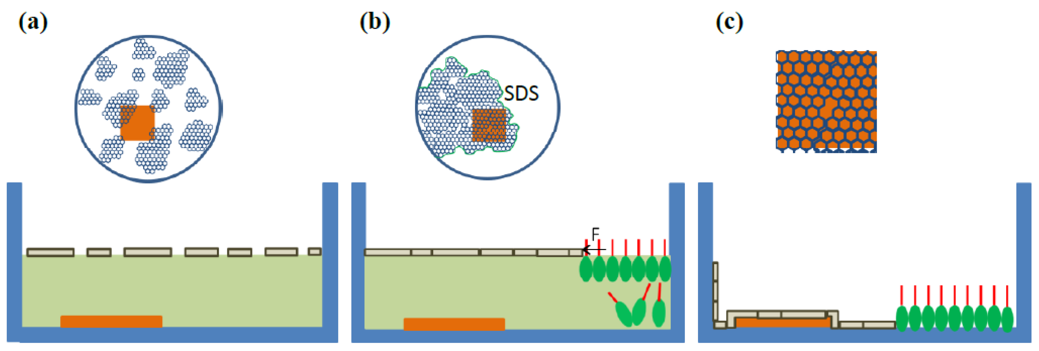
The principle of the DSA process [
27,
30,
31] is illustrated in
Figure 1 as a cross-sectional view. The graphene suspension is dispersed onto the water surface by a syringe to form a loose MGFs floating on the water surface (
Figure 1a). Subsequently the loose MGFs are laterally compressed by sodium dodecyl sulfate (SDS) molecules added at the edge of the water surface [
30,
31]. During the fast spreading of the SDS molecules on the water surface, the graphene flakes are pushed together and form dense MGFs (
Figure 1b). Then the water is pumped out or the samples are raised up to let the MGFs settle down on the substrate. After drying the substrate, the MGFs attach to the substrate (
Figure 1c).
A slight excess of SDS is essential to stabilize the MGFs during the deposition. The SDS molecules stay mostly beneath the water surface at the place where they are injected. The area occupied by the MGFs is reduced due to the deposition on the substrate as well as on the side wall of the petri dish during the lowering of the water level. The area free of graphene increases and is newly occupied by SDS molecules to maintain the pressure at the edge of the MGFs. The excess SDS molecules emerge on the water surface in a self-assembly way so that the area free of graphene flakes is always fully occupied by SDS molecules, and the pressure at the edge of the MGFs is maintained. This occurs in a very fast and smart self-assembled way so that the dense MGFs is stabilized and hold together during the deposition. In addition, the individual graphene flakes within the MGFs floating on the water surface can still rearrange their positions by self-assembly during the entire deposition to fit the contour of the substrate, so that a uniform and conformal coating of MGFs on 3D structures can be guaranteed. This is the origin of the name of the double self-assembly (DSA). It is noted that SDS surfactants have been used as a stabilizer mixed with carbon nanotubes for the formation of stable suspension [
32,
33]; in such cases, the SDS molecules bind on the surface of carbon nanotubes forming micelles in the suspension. The SDS molecules are used in a different way in our case; they were intentionally used to compress the graphene flakes on the water surface, and the SDS molecules have no contact at least with the graphene flakes in the middle. The pressure exerted by the SDS molecules stabilizes the MGFs floating on the water surface, so that no cracks in the MGFs form during the deposition.
2. Materials and Methods
All the petri dishes, glass beakers, syringes, and substrates used in these experiments were thoroughly cleaned by acetone and dried by N
2 blowing. Then they were rinsed in deionized water several times. For the textiles a slightly different cleaning without acetone was needed. The textile was immersed into deionized water for several minutes and then the water was discarded. The procedure was performed repeatedly several times in order to remove contaminations from the textile. After the cleaning, the petri dish with the sample was filled with several hundred mL deionized water until the water level is about 5 mm above the sample. The graphene flakes used here were emulsifier-free and thermally reduced few-layer graphene oxide (TRGO) initially developed for printed electronics at the University Freiburg [
27,
34], and contain 5 g·L
−1 functionalized TRGO suspended in a slightly alkaline water (pH 9–10 adjusted by NaOH) solution. The size of the graphene flakes was about 100 nm up to several µm. About 500 µL of the graphene ethanol suspension (graphene content: 0.5 wt %) was added onto the water surface by a syringe until the water surface was fully occupied. The flakes spread over the water surface and formed a loose monolayer. About 200 µL of 10 wt % SDS water solution was added by another syringe at the edge of the petri dish, so that during the spreading of the SDS molecules on the water surface, the loose MGFs was laterally compressed and formed a dense MGFs (see
the Video S1 in the Supplementary Material).
After adjusting the position of the substrate beneath the MGFs, the water was slowly pumped out, so that the MGFs settled down on the substrate. This was the method for deposition on PTFE, textile samples, and 3D structures.
For the coating of glass fibers, the fibers were dipped vertically into the water at the area free of graphene flakes and pulled out of the water from the area with the dense MGFs. The MGFs attached onto the surface of the glass fibers driven by the pressure applied by the SDS at the edge of the MGFs. For multiple layer deposition, a drying step at 80 °C for about 10 min was required after each deposition. This drying step improves the adhesion of the previous graphene layers so that the first layer(s) will not detach from the surface during the subsequent processes performed in water. The conductivity can be improved by thermal annealing in inert gas N
2 at temperatures between 200 and 600 °C if necessary [
27].
The adhesion of the MGFs on Borofloat glass (Borofloat® 33 with a surface roughness of <1 nm) substrates was investigated using scotch tape peel tests. To better visually demonstrate the effect, samples partially coated with MGFs were used, so that the contrast between the MGFs and the areas without MGFs could be better visualized. The tests were repeatedly performed several times around the same area. After each peel, the scotch tapes were stuck on a white paper close to each other for comparison.
3. Results
The sheet resistances, annealing behaviors, and Raman measurements of the graphene layers deposited on flat glass substrates are reported elsewhere [
27].
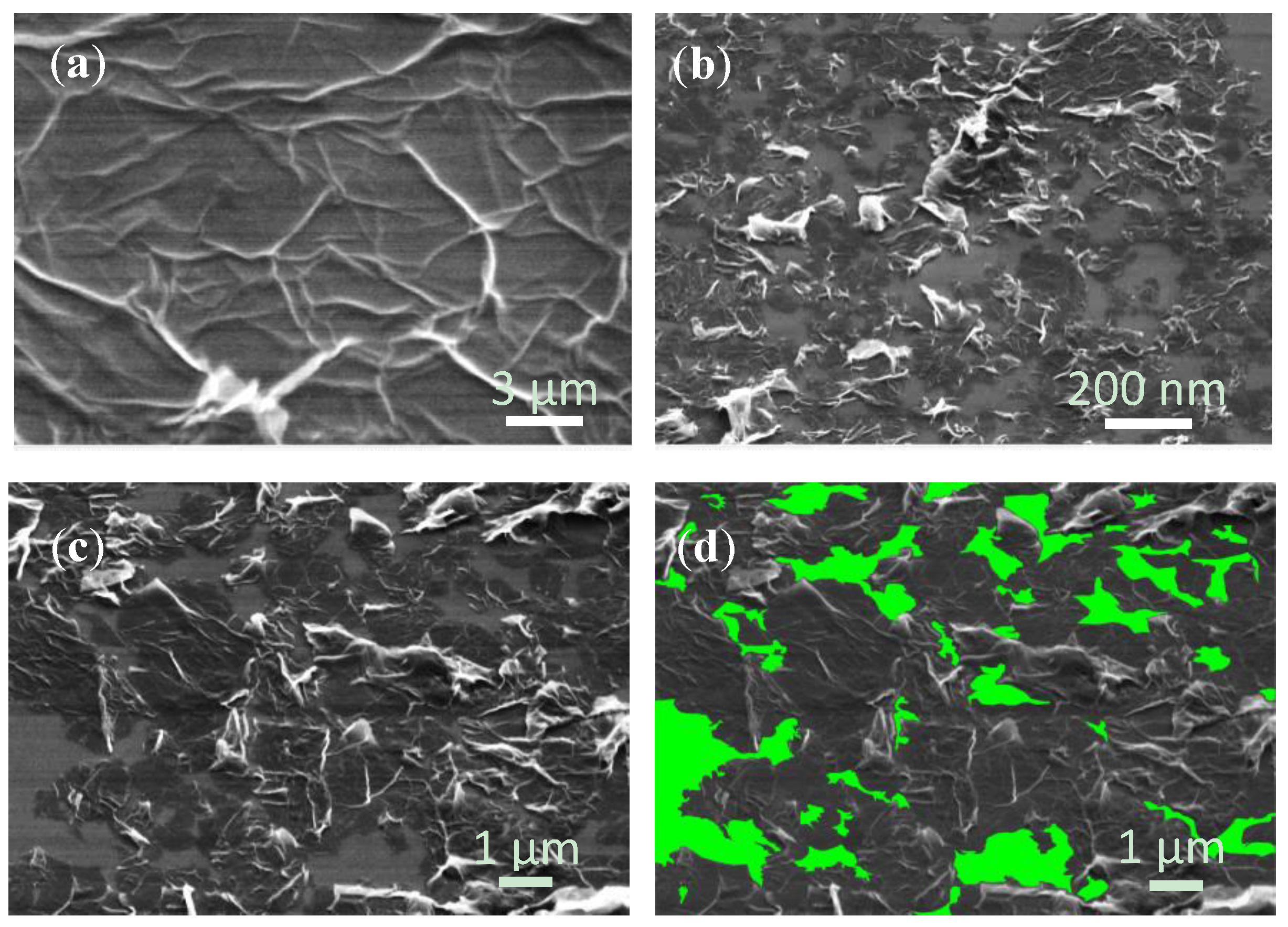
Figure 2a shows the SEM image of the dense MGFs deposited on a silicon wafer along with some graphite nanoparticles. These particles were possibly the residual non-fully exfoliated graphite. The SEM investigation was done on silicon, since a conductive substrate was needed to avoid charging, but the same morphology was expected on other substrates. The corresponding high magnification image in
Figure 2b shows a graphene flake with wrinkles, which are typical for the solution proceeded graphene layers [
27]. The neighboring graphene flakes were connected to each other but some bare areas appear between the flakes. The area coverage ratio of the graphene flakes was estimated to be 84.1%–85.3% as shown in the example in
Figure 2c and the corresponding processed image in
Figure 2d. The non-covered area was 14.7%–15.9% and the average size of blank area of 0.01–10 µm
2.
Except of the versatile possibilities of coating of the MGFs on different substrates demonstrated in [
27], in this work we have tested the applicability of the DSA process for the coating on very challenging samples such as highly hydrophobic surfaces such as PTFE, very flexible textiles, the conformal coating on 3D structures, and even with very large curvatures in case of glass fibers with very small diameters.
3.1. Large Area Deposition on Highly Hydrophobic Surfaces
One of the advantages of the DSA compared to the LB process is that it does not need a hydrophilic substrate surface. It can be readily applied to almost any hydrophobic surfaces [
27]. A representative example of the MGFs deposition on a highly hydrophobic surface was demonstrated on PTFE in this work. A contact angle of 103° ± 2° of deionized water on PTFE was measured before the MGFs deposition.
Figure 3a shows the dense MGFs floating on the water surface above the PTFE sample after compression with SDS molecules.
Figure 3b shows the MGFs attached to the PTFE surface (diameter of 4.1 cm) with an area of about 13 cm
2 after lowering the water level. The deposited graphene layer was very homogenous and conductive even without further treatment and annealing.
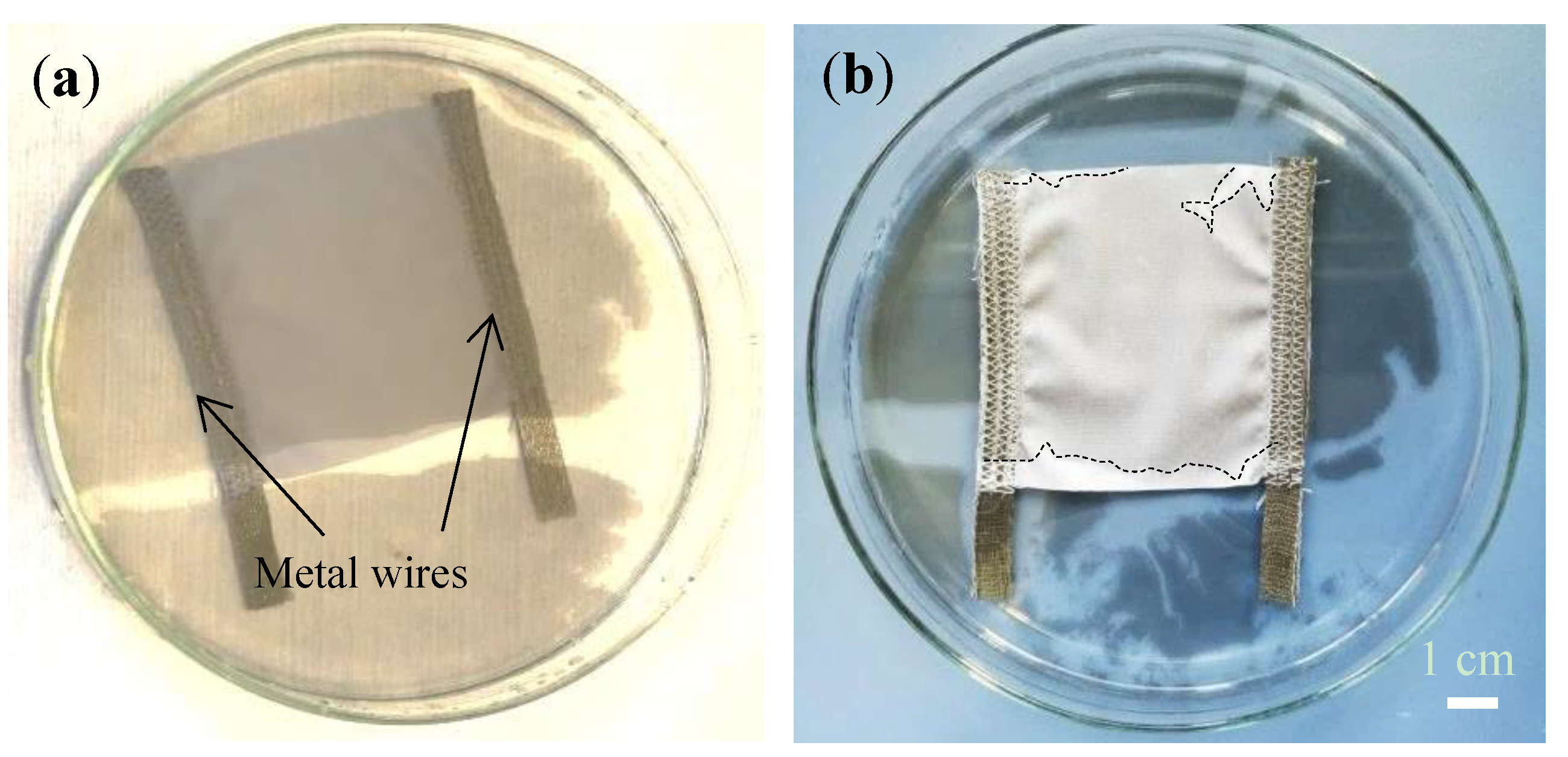
3.2. Deposition on Flexible Textiles
A homogeneous coating of a graphene layer on very flexible substrates such as textiles and carbon fiber [
35] is essential for many applications including e-textile [
36], textile based sensors [
37], etc. Due to the strong compression by the surfactant molecules, the DSA process can be applied to textile materials immersed in water.
Figure 4a shows the cleaned textile with interwoven metal wires being immersed in the water beneath the dense MGFs.
Figure 4b shows the uniform MGFs deposited on the textile surface after drying. The deposited graphene layer was about 30 cm
2 large and showed no visible defects.
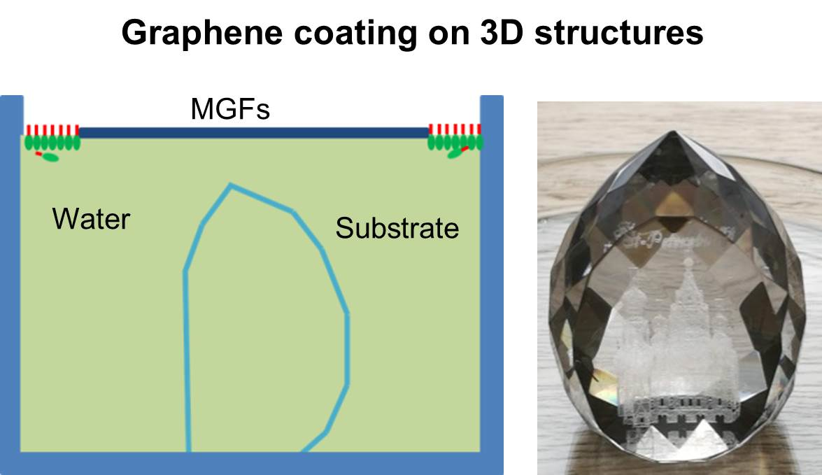
3.3. Conformal Deposition on 3D Structures and Thin Glass Fibers
A conformal coating of the MGFs on complex 3D structures is one of the unique features of the DSA process, mainly due to the smart rearrangement of the SDS molecules and graphene flakes. The graphene flakes fit the contour of the 3D structures and a conformal coating without folding is thereby achieved [
27].
In this work, we have successfully demonstrated a uniform coating of MGFs on 3D objects in case of a laser engraved glass souvenir with many facets. The glass souvenir was placed beneath the MGFs as shown in the
Figure 5a. A conformal and homogeneous coating of the MGFs was achieved on the 3D glass substrate as sketched in
Figure 5b and shown in the photographs in
Figure 5c–e. Despite the complex structure, a very homogeneous and uniform coating of MGFs was achieved on the facets as well as on the flat front window without any folding. In contrast, if a flat graphene layer (like a sheet of paper) is to be attached onto 3D objects, it is impossible to do so without folding. The height of the souvenir was about 4 cm, the lateral broadness about 3 cm, and the diameter of the bottom about 2 cm, so the area coated with MGFs was estimated to be around 35 cm
2. The layer was conductive with resistance of several mega ohm measured between any two points on the graphene even without further treatment and annealing.
It is demonstrated in this work that a conformal coating can also be achieved on bended surfaces with very large curvatures (i.e., small diameters).
Figure 5f illustrates the procedure for the coating of a MGFs on a thin glass fiber. The fiber was pulled out of the water at the area formed with the MGFs, so that the MGFs were attached uniformly on the fiber due to the pressure exerted by the SDS molecules at the edge of the MGFs as sketched in
Figure 5g. Several layer stacks of MGFs were easily realized on the fibers by repeating the process as shown in
Figure 5h, where glass fibers with diameters of 0.42 (upper) and 0.93 mm (lower) were coated with MGFs all around the fibers (the 5 euro cents coin is for comparison). The layer is also conductive even without further treatment and annealing. An adaption of the DSA process could enable graphene coating on longer fibers.
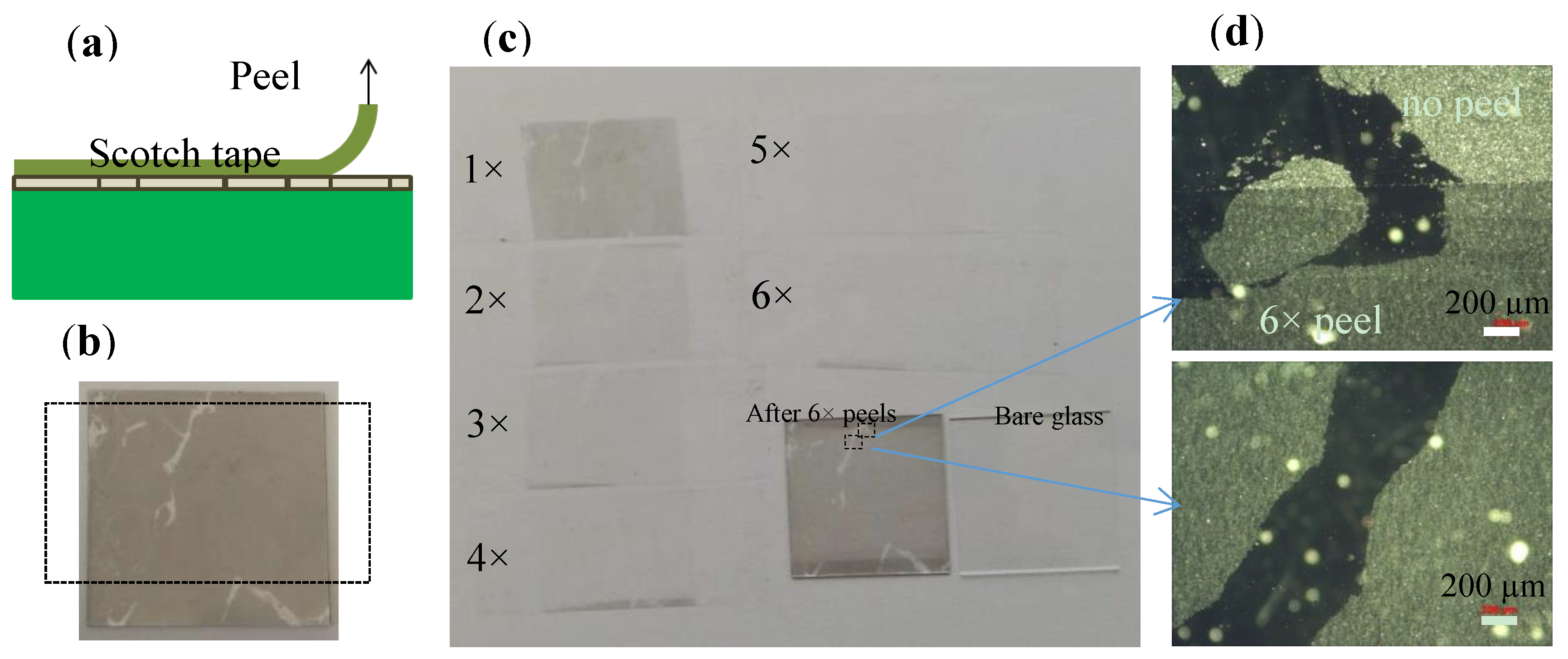
3.4. Adhesion of the MGFs Deposited on Flat Borofloat Glass
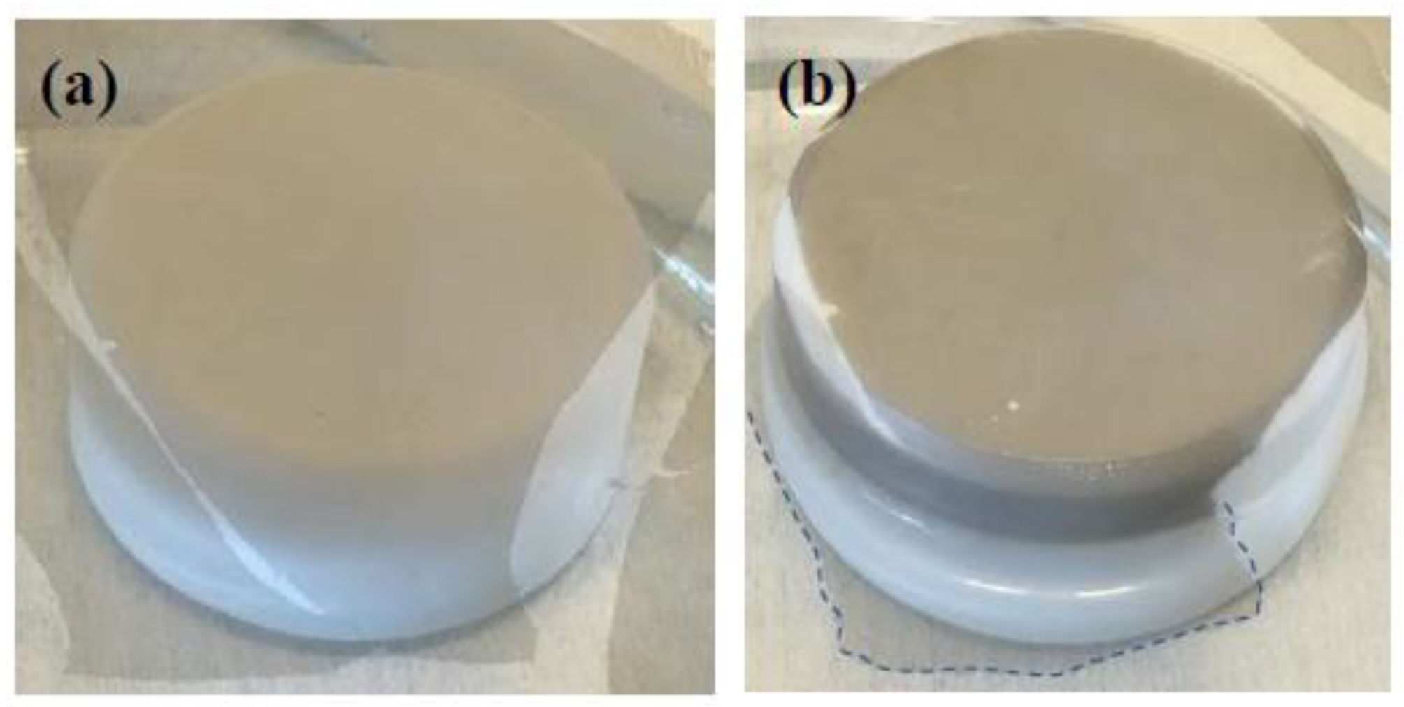
Adhesion of graphene layer on foreign substrates is crucial for almost all applications. Here we present our preliminary results for MGFs deposited on glass substrates using the DSA process. The adhesion of the MGFs deposited on Borofloat glass was tested by scotch tape peel as shown in
Figure 6a. The photo in
Figure 6b shows a 2.5 × 2.5 cm
2 sample partially deposited with MFGs for better visual control. It shows that the first peel effectively removes the highly reflecting particles in the layer, which are well visible in microscope, and corresponds to remaining graphite nanoparticles in the suspension [
27].
The structures of the MGFs on the tapes (with a width of 1.9 cm in
Figure 6c) were still seen for the next two peels, while there was only very faint contrast seen on the tape after the fourth peel, and almost nothing at all can be seen for the fifth and sixth times. However, after 6 peels, a uniform thin film (at the areas originally covered with MGFs on th) remained e Borofloat glass substrate and the structure of the thin film kept the same as previously. The micrographs in
Figure 6d show that the highly reflecting graphite nanoparticles [
27] were mostly removed by the peels, while the graphene flakes stayed on the flat glass substrates. We believe that the good adhesion of the graphene flakes on the glass could be attributed to the van de Waals force between the graphene flakes and the smooth glass surface, since the smooth surface allowed a much better contact between the graphene flakes and the glass substrate, so that a large van de Waals force exists between them.
The scotch tape peel tests give strong evidence that the MGFs has a good adhesion on the flat glass substrates. Upon further selection process to filter out the graphite nanoparticles, a better MGFs with super adhesion could be produced. These peel tests demonstrated the good adhesion of the graphene flakes deposited on the flat glass surface. However, it is generally known that the adhesion of any coating depends strongly on the surface properties (roughness, chemical bonding, etc.) of the substrates, and has to be investigated for each of the targeting substrates individually.
4. Outlook
The advantage of the DSA process is that it is able to deposit pure graphene thin layer onto targeting substrate, and there is no surface functionalization of the targeting substrates required and it is possible to only use ethanol, graphene flakes and water for the suspension. It is a binder-free coating in comparison to other approaches [
38,
39], and the ethanol and water are vaporized completely during the drying. During the compression, the SDS molecules stay at the edge of the MGFs and beneath the water at the place where they are dispersed. The substrate can be placed far away from this point, so that the SDS molecules are not able to reach the substrate during the deposition and a very pure graphene layer can be deposited on the substrate. Such a pure graphene layer is essential for many applications; for example, for microelectronics, sensors, and electrodes for Li-ion batteries.
The deposition is very fast; usually the pumping of water can be done at a rate of about 2 cm/min in the vertical direction. This does not depend on the lateral size of the sample, so large flat areas can be deposited with MGFs within a minute.
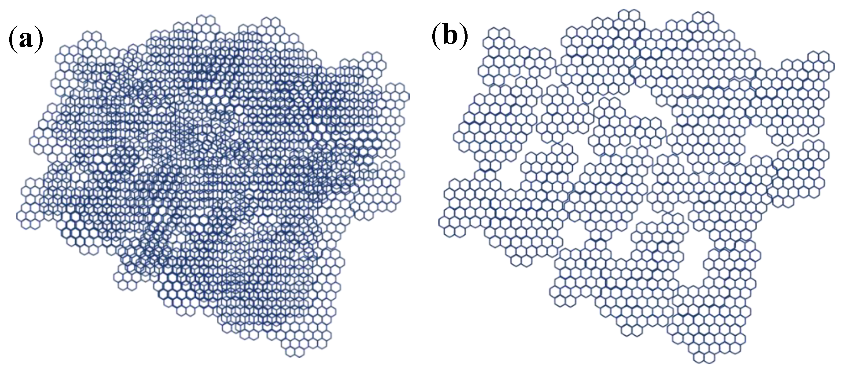
The DSA process is able to compress the graphene flakes so that they are linked to each other at the edges, with some bare spaces between neighboring flakes due to the irregular shape as shown in the schematic view in
Figure 7a. It has been demonstrated that these bare spaces get closed if the process is repeated and multilayer of MGFs are deposited [
27]. An ultrathin membrane can be formed as shown in the schematic view in
Figure 7b. Theoretically, the blank area of membranes consisting of multilayers of MGFs can be estimated from that of the monolayer, and the values are listed in
Table 1. If the average size of the blank area is 0.01 µm
2, seven layers of MGFs are needed in order to get it down to sub-nm range (an average size of the blank area below 1 × 10
−6 µm
2). For the blank area at the maximum of 10 µm
2 (three orders higher than 0.01 µm
2), a further three layers of MGFs are needed to get a closed membranes. In both cases, the thickness of the membranes is below 10 nm if the graphene flakes consist only with one atomic layer of carbon (thickness of ~0.3 nm).
These closed ultrathin membranes (or coating) can be used for high performance molecular sieving purposes, in which the membrane allows small molecules such as H
2 and H
2O to pass [
40,
41], while remaining impermeable to larger molecules such as CH
4, ethanol [
42] and ions (Na
+, Cl
−, Mg
2+, Ca
2+, etc.) [
43].
Such ultrathin membranes are required for gas separation and can also be used for reverse osmosis in water desalination and purification. The ultrathin membrane allows a high flux at very low pressure and will significantly reduce the power consumption of the process [
40]. The DSA process could contribute to the scalable fabrication of ultrathin membranes.
Furthermore, such impermeable coatings on 3D metal parts are expected to have the ultimate anti-corrosion effect [
14,
15,
16]. The main reason for metal (alloy) corrosion is an electrochemical process, which occurs between two metals or phases with different electrochemical potentials in the presence of an electrolyte. Thus a micro electrochemical cell is formed, with one phase acting as anode and the other as cathode. The metal at the anode oxidizes and corrodes by releasing ions. With the hermetic graphene layers deposited under pure conditions (deionized water), it is expected that no electrochemical process on the metal surface can take place, since no electrolyte can be formed on the surface due to the absence of salts, and no salts can pass through the hermetic graphene coating during the operation. In comparison with other anti-corrosion coatings, the graphene layers are ultra-thin in the nm-range, and it is resistant to many other aggressive chemicals such as strong acids and alkalis. Furthermore, graphene is thermally stable up to 500 °C in air and about 2700 °C in vacuum [
44], so such an anti-corrosion coating might be used for critical parts working in extreme hazardous conditions.
Owing to the process compatibility to other 2D materials, the DSA process might be used for the large-scale thin film deposition of other 2D materials as well, and will greatly contribute to application of 2D materials.
5. Summary
In this work it is demonstrated that the DSA process can be used to deposit conformal graphene layers on highly hydrophobic substrates such as PTFE, on flexible textiles, on complex 3D objects, and even on single glass fibers with small diameters as low as 0.42 mm. Together with our former work, a full spectrum of the DSA process for MGFs deposition has been demonstrated.
The DSA process works without explosive gases, vacuum, high temperature, or special equipment, and only non-toxic environmentally friendly materials are used. This process allows uniform deposition of MGFs on almost any substrates such as flexible transparent plastic foils, metal sheets, glass substrates, silicon wafers with or without SiO2, and rough surfaces for the above-listed applications. Particularly, the DSA process allows a uniform and conformal coating on complex 3D structures, which opens many applications of the low-cost graphene feedstocks such as anti-corrosion coating on critical parts working in extreme conditions, functional coating on optical components including “free-form” optics, and antistatic coating.
The DSA process allows MGFs to be repeatedly deposited on the same substrate, that is, to prepare uniform multilayers with well-ordered graphene flakes within each layer stack. This allows a precise layer thickness and morphology control; for example, to produce ultrathin membranes for highly efficient water desalination and gas separation applications, as well as impermeable anti-corrosion graphene coatings on 3D parts used at extreme conditions (corrosive, high temperature, etc.).
We expect that the DSA process will greatly contribute to large-scale high performance applications of low-cost graphene feedstocks and other 2D materials, and is industrial compatible to trigger scalable applications up to the m2-range. The good adhesion of the MGFs on flat substrates demonstrated in this work is another key point for up-scalable applications of the low-cost graphene flakes.


