Article

Hydrothermal Synthesis of Protective Coating on Mg Alloy for Degradable Implant Applications

1
Key Laboratory of Superlight Material and Surface Technology, Ministry of Education, College of Material Science and Chemical Engineering, Harbin Engineering University, Harbin 150001, China
2
Department of Materials Physics and Chemistry, Harbin Institute of Technology, Harbin 150001, China
*
Authors to whom correspondence should be addressed.
Coatings 2019, 9(3), 160; https://doi.org/10.3390/coatings9030160
Submission received: 26 January 2019 / Revised: 21 February 2019 / Accepted: 26 February 2019 / Published: 28 February 2019
(This article belongs to the Special Issue Surface Engineering of Light Alloys)

Abstract

:
Biodegradable magnesium (Mg) alloys are known as “the new generation of biomedical metal materials”. However, high degradation rates restrict their clinical application. To overcome this issue, a new and simple method for producing of protective coating based on hydrothermal synthesis at 200 °C in 0.5 M NaHCO3 was elaborated. The microstructure, elemental and phase composition of the produced films were examined by scanning electron microscope (SEM), X-ray energy-dispersive spectrometer (EDS) and X-ray diffraction (XRD). The mechanical strength of the protective coating was evaluated by grid scribing method. The corrosion protection effect was evaluated using linear sweep voltammogram (LSV) and electrochemical impedance spectroscopy (EIS) methods in the simulated body fluid (SBF). Since the corrosion process is accompanied by stoichiometric evolution of hydrogen, the amount of the latter was measured to quantify the overall corrosion rate. Both the coatings morphology and phase composition were sensitive to the treatment duration. The coating formed after 0.5 h was loose and mainly consisted of spherical flower-like Mg5(CO3)4(OH)2·4H2O accompanied by small amounts of Mg(OH)2. The treatment duration of 3 h resulted in a thicker compact coating composed mainly of irregular granular MgCO3 as well as Mg(OH)2. The coating providing the most effective protection and uniform corrosion was achieved by 2 h treatment at 200 °C.

1. Introduction

Mg alloys have attracted much attention for their potential use as a new class of biodegradable medical implant materials, as they possess good biocompatibility [1]. Mg alloy are biodegradable, and their degradation products can be excreted through human metabolism. Furthermore, Mg is an essential element for human organisms, which could have stimulatory effects on the bone grafting. The density and the elastic modulus of Mg alloys are close to those of natural bones [2]. Therefore, Mg alloys are known as “the new generation of biomedical metal materials” [3]. The biological applications of Mg alloys are limited mainly due to their too rapid degradation rate for most implanted devices [4,5]. Although some studies related to the corrosion/degradation behavior of Mg and Mg alloys have been intensively carried out [6], further research is still needed to improve their corrosion characteristics and surface properties.
To improve the corrosion resistance of Mg alloys, surface modification has become the research focus of medical Mg alloys [7]. Chemical conversion coatings [8,9], electrochemical coatings [10,11], polymer coatings [12,13], ceramic coatings [14,15], ion implantation coatings [16,17], composite coatings [18,19] etc. improve the corrosion performance of Mg alloys. The drawbacks of these methods are often complicated process, limited corrosion protection, poor biocompatibility and poor adhesion [20,21,22,23,24]. While passivation of the Mg surface by oxidation is a very simple process, the spontaneously formed oxide coating is loose and does not provide effective corrosion protection. Alkaline heat treatment, however, is a simple method which effectively improves the corrosion resistance of Mg alloys because of the compact oxide film that forms [25]. As a special chemical method, hydrothermal treatment has been gradually introduced into the corrosion prevention of Mg alloys in recent years [26,27]. In this study, we applied a hydrothermal treatment in aqueous NaHCO3 solution to the high-performance biomedical Mg6Ho0.5Zn alloy.
The selected substrate Mg6.659Ho0.536Zn0.005Fe0.002Ni0.007Cu, wt.% extruded alloy, is a promising biodegradable medical material [28]. Nano-spaced and solute-segregated basal plane stacking faults (SFs) with an extremely large aspect ratio, can be formed and distributed uniformly throughout the fine dynamic recrystallized (DRXed) grains in the as-extruded Mg6Ho0.5Zn alloy by adding Ho and Zn and controlling their ratio as well as appropriate preparation processing parameters. Compared with alloys possessing classic microstructure, the new alloy with profuse SFs exhibits uniform in-vitro and in-vivo corrosion behavior, low corrosion rate and optimal mechanical properties. In addition, the Mg6Ho0.5Zn alloy shows no significant toxicity to Saos-2 cells.
In this paper, the effect of the hydrothermal treatment duration on the morphology, composition, mechanical and electrochemical properties of the protective coating formed on the Mg6Ho0.5Zn substrate surface were investigated. It should be noted that the hydrothermal treatment may not be limited only to the Mg6Ho0.5Zn alloy, but might be suitable for other Mg alloys as well.

2. Materials and Methods

2.1. Samples Preparation

The alloy with nominal composition Mg6.659Ho0.536Zn0.005Fe0.002Ni0.007Cu, wt.% and its special structure and outstanding corrosion behavior was reported [29]. The substrate samples were ground and polished with SiC abrasive papers from P120 down to P2000 to achieve a smooth surface and get rid of impurity layer and then degreased with ethanol and acetone (1:1) in ultrasonic bath for 10 min, followed by drying in the air.
Four sets of samples were prepared by hydrothermal treatment in 0.5 M NaHCO3 aqueous solution at 200 °C in the autoclave for 0.5, 1, 2 and 3 h, followed by drying at 200 °C for 1 h. These hydrothermally treated samples were designated as HT0.5, HT1, HT2 and HT3 respectively.

2.2. Characterization

The morphology and phase composition of the coatings were examined by scanning electron microscope (SEM, Quanta 200 FEG, FEI, Hillsboro, OR, USA) equipped with X-ray energy-dispersive spectrometer (EDS, Quanta 200 FEG, FEI, Hillsboro, OR, USA) and X-ray diffraction (XRD, D/MAX-Ultima Ⅲ, Rigaku Corporation, Tokyo, Japan).
To test the mechanical strength of the coating, a grid was scribed on the sample surface using a sharp blade and controlled by SEM.
Linear sweep voltammogram (LSV) and electrochemical impedance spectroscopy (EIS) measurements were conducted in the simulated body fluid (SBF) using PGSTAT302N potentiostat (Metrohm Autolab, Utrecht, The Netherlands). The composition of the SBF is depicted in Table 1. The SBF was buffered with Tris-HCl and the pH 7.4 was set. A three-electrode cell set-up was used, with the tested sample as the working electrode (WE), a platinum wire as the counter electrode (CE) and a saturated calomel electrode (SCE) as the reference electrode (RE). Prior to electrochemical measurements, samples were kept in the SBF for 0.5 h. LSV was conducted in the potential range from −300 to 300 mV vs open circuit potential (OCP) at 2 mV/s. EIS was performed at OCP, and 10 mVRMS AC excitation signal amplitude in the frequency range from 100 kHz to 10 mHz.
Long-term corrosion behavior was evaluated by immersion in SBF at 37 ± 0.5 °C for 5 days. The evolved hydrogen was continuously collected by means of the funnel and the burette above the sample. To compensate the pH shift due to hydrogen evolution, the SBF was replaced every 36 h and the SBF amount was controlled to be 30 mL/cm2 of the sample surface.

3. Results and Discussion

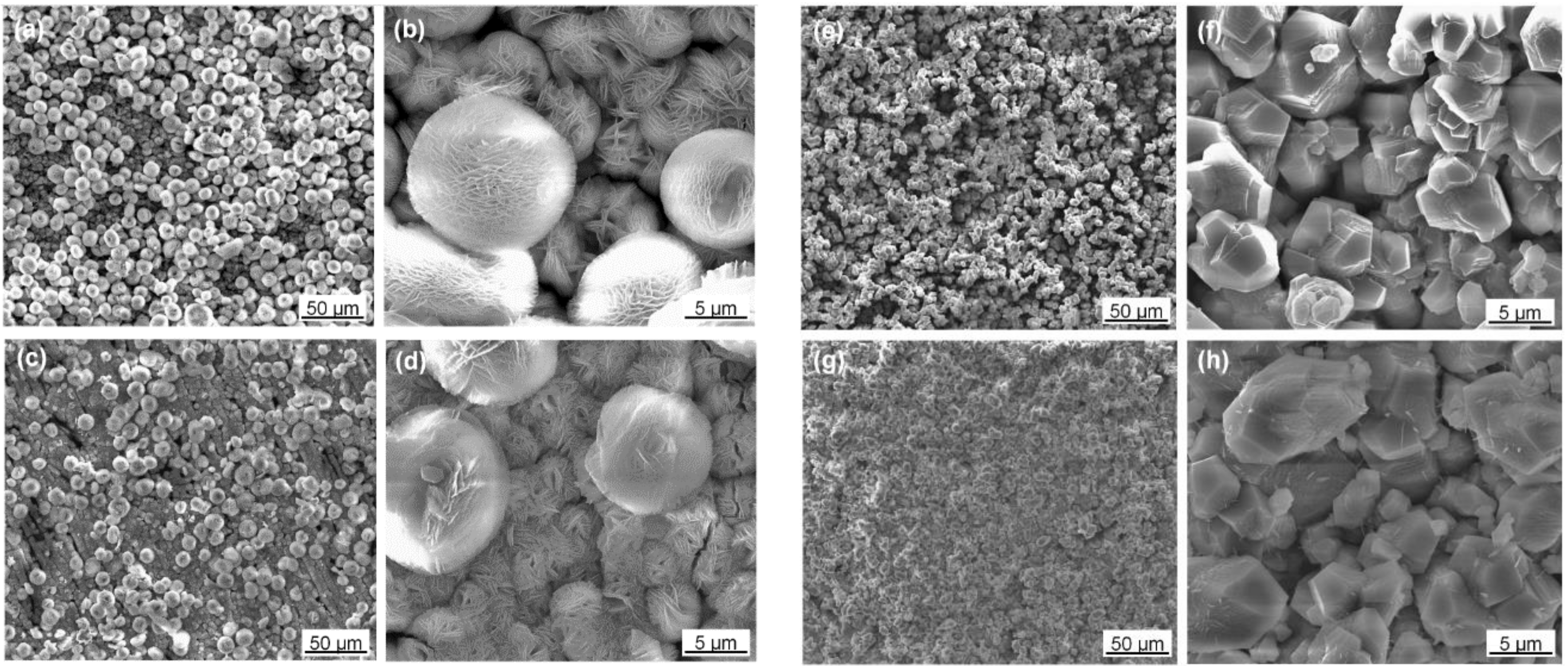
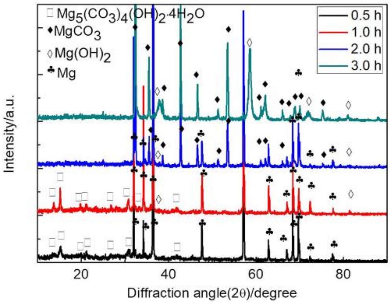
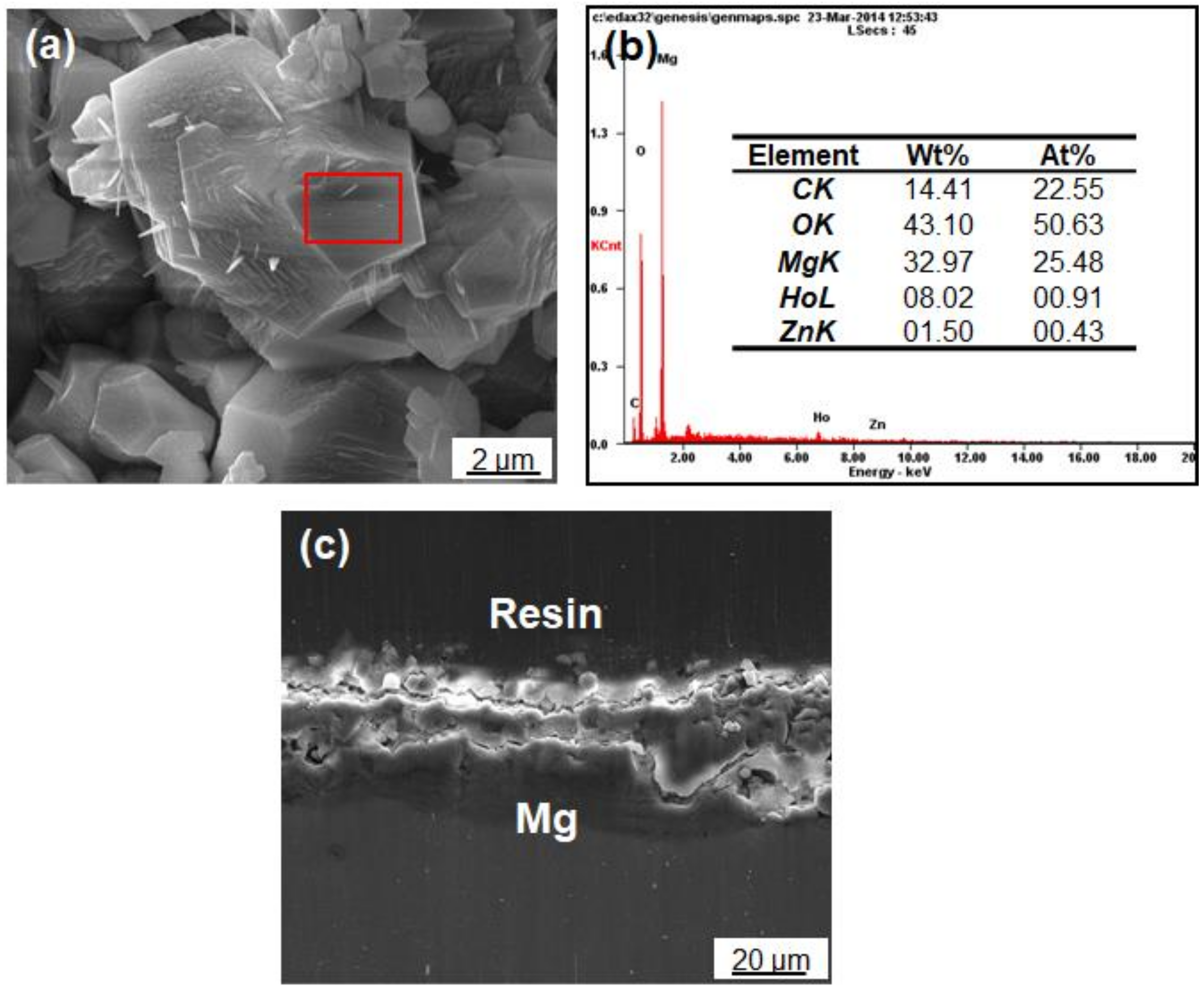
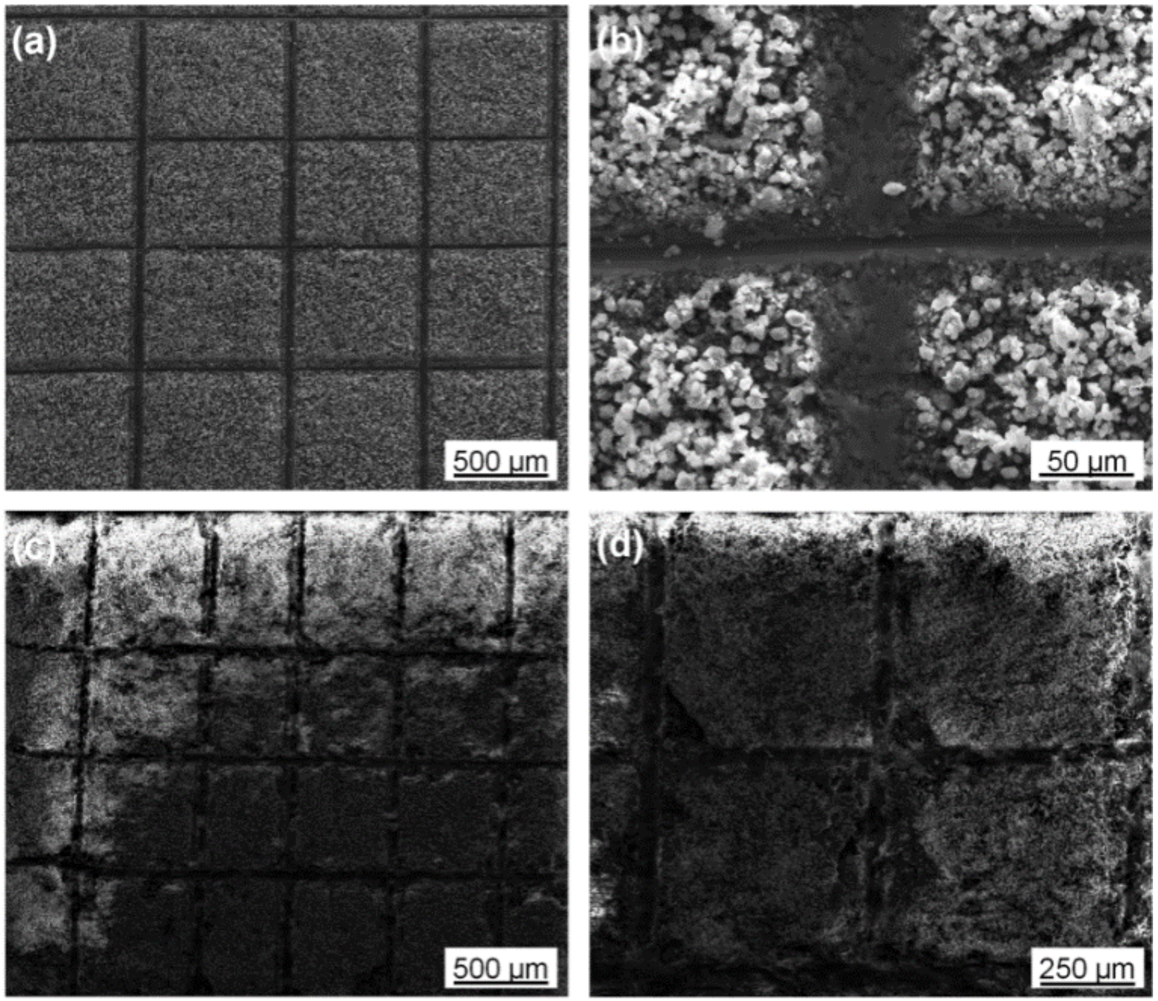
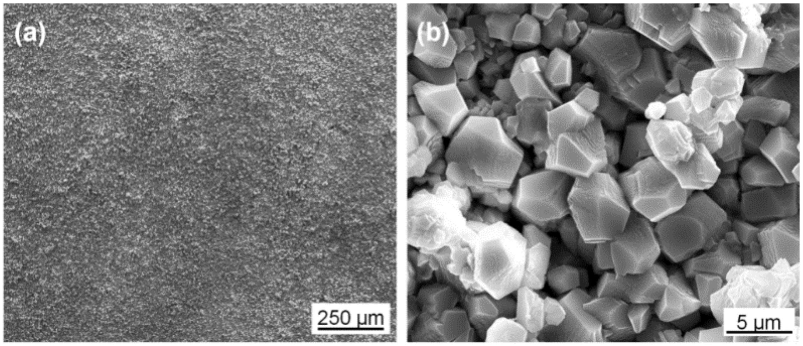
3.1. Morphology and Composition

Figure 1 shows SEM micrographs of the four samples after hydrothermal treatment with different durations. Two distinguishable morphologies were formed: the coating of the samples HT0.5 and HT1 consisted of numerous spheres with the diameter ranging from 4 to 10 μm. Smaller spheres composed compactly aggregated layer, while larger spheres were scattered on the compact layer surface (Figure 1a–d). The spheres itself are composed of thin nano-flakes. Remarkably, the nano-flakes grew together forming rather dense spherical particles once the treatment duration was prolonged. The morphology was changed cardinally after 2 h of the treatment (sample HT2—Figure 1e,f): the surface was composed of numerous irregular particles of about 3–5 µm. The compactness and uniformity of the coating were also enhanced. Further prolongation of the synthesis time does not change the morphology very much: the film got denser and more compact (sample HT3—Figure 1g,h).
HT0.5 and HT1 mainly consisted of Mg5(CO3)4(OH)2·4H2O, as it can be seen from XRD patterns (Figure 2). Diffraction peaks of these two samples also indicated the presence of small Mg(OH)2 quantities. In contrast to this, the main phase composition of the HT2 and HT3 samples was MgCO3 with a few Mg(OH)2 inclusions. Thus, the duration of the hydrothermal treatment influences both the morphology and the composition of the formed coating.
The film thickness build-up can also be followed by XRD patterns. Thus, the intensity of Mg diffraction peaks, which come from the substrate alloy, are roughly the same for the HT0.5 and HT1 samples, indicating, that the coating thickness is also comparable. In the case of the HT2 sample, the intensity of the Mg diffraction peaks drops significantly, indicating increase of the coating thickness, as well as its compactness. It is worth noting that the different phase may have different X-ray absorption behavior. Finally, the HT3 sample shows no Mg diffraction peaks, thus the formed coating is thicker, than that of the HT2 sample. These observations also agree with the morphology change detected by SEM.
To support the XRD data, elemental analysis of the HT2 sample was carried out by SEM-EDS, as shown in the Figure 3a,b. The C/O atom ratio was 1:2.25, which roughly represents the MgCO3 phase detected by XRD. The cross-sectional morphology of this hydrothermal film was also observed by SEM, as shown in the Figure 3c and the coating thickness amounted to 15–20 μm. Considering an in-situ formation of the coating, a good adhesion of the carbonate layer to the substrate alloy can be assumed. This is indirectly confirmed by the absence of cracks and caves.

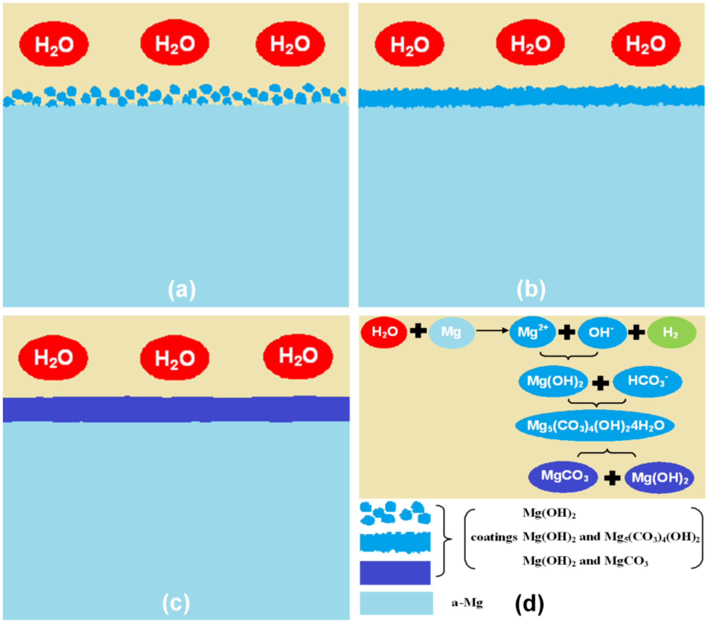
3.2. Formation Mechanism

Based on the observations made, the formation of the coating can be divided into three stages: nucleation, transformation and densification, as schematically shown in the Figure 4. First, Mg2+ and OH are formed as products of redox reaction between water and magnesium metal with corresponding half-reactions:
2 H 2 O   +   2 e H 2   +   2 OH
Mg     2 e Mg 2 +
The rates of these reactions are crucial in defining the overall coating nucleation rate:
Mg 2 +   +   2 OH Mg ( OH ) 2
Since the reaction conditions accelerate the Mg oxidation by water, the nucleation rate is rather high, which results in the loose spherical Mg(OH)2 particles (Figure 4a). Since the formed coating possesses many channels, the electrolyte can penetrate it and stands in the direct contact to the metallic substrate. As a result, such coating cannot provide enough protection against corrosion. During the transformation phase (Figure 4b) the carbonate ions partially substitute hydroxide forming mixed hydroxycarbonate:
5 Mg ( OH ) 2   +   4 HCO 3 Mg 5 ( CO 3 ) 4 ( OH ) 2 · 4 H 2 O   +   4 OH
The transformation of the coating may occur in the whole bulk of the Mg(OH)2 as the non-converted coating can be penetrated by the electrolyte as mentioned above. The hydroxycarbonate carbonate decomposes due to its instability:
Mg 5 ( CO 3 ) 4 ( OH ) 2 · 4 H 2 O 4 MgCO 3   +   Mg ( OH ) 2   +   4 H 2 O
forming magnesium carbonate and magnesium hydroxide, while the latter, again, can react with carbonate ions. The MgCO3 layer is compact and uniform.

3.3. Mechanical Strength

The coating compactness increases with the treatment duration, however, there is a trend off between the compactness, which is crucial for the efficient corrosion protection, and mechanical strength, which is important for the long-term stability of the coating. The adhesion of the coating was tested for the samples HT2 and HT3 according to the method described in the experimental section. Figure 5 depicts SEM micrographs of the HT2 (Figure 5a,b) and HT3 (Figure 5c,d) samples after the strength test. The HT2 coating remained unchanged, maintaining its compact structure. No further damages of the coating could be found at the cut sites, thus it can be concluded that the coating exhibits sufficient mechanical strength and adhesion to the metal substrate. This is not the case for the HT3 sample, where obvious delamination occurred. Thus, it is clear that the thicker coating loses its mechanical strength, followingly losing its corrosion protective properties. Based on this, the hydrothermal treatment duration of 2 h is the optimum treatment duration.

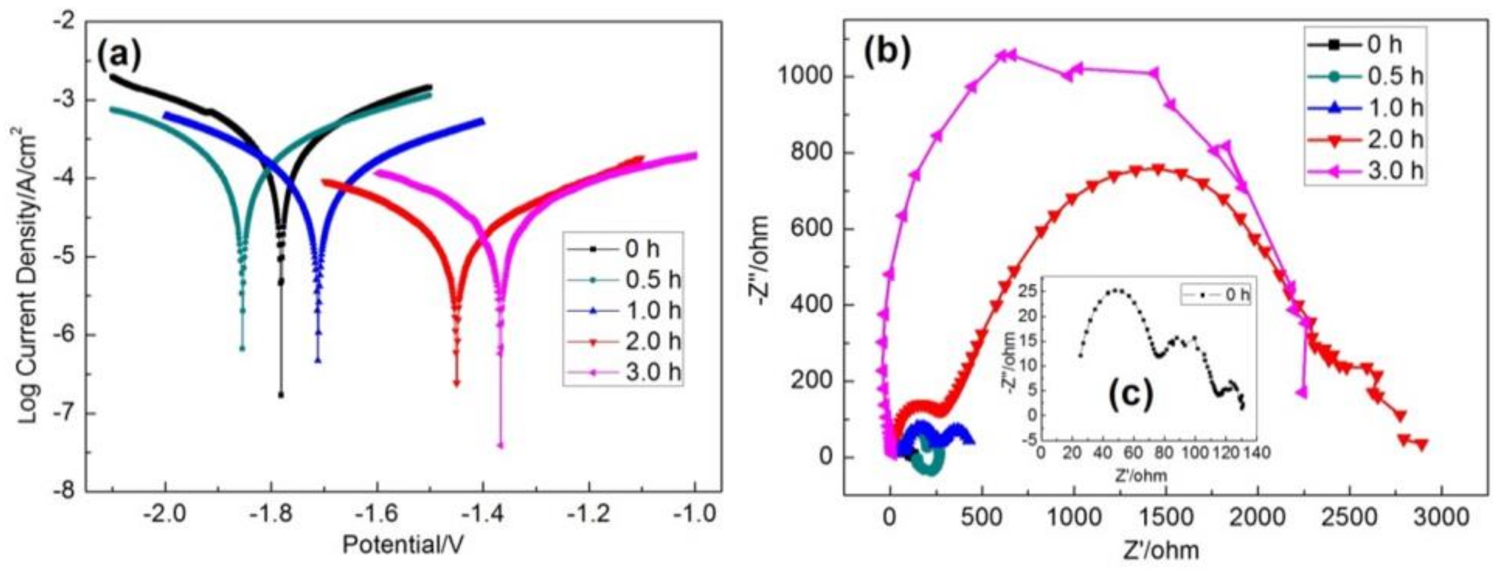
3.4. Electrochemistry

Break-through potential of the samples was determined by means of LSV. Prior to polarization, samples were conditioned at OCP for 0.5 h. The break-through potential (Ecorr) and corrosion current density (Jcorr) were derived from the Tafel-type plot (Figure 6a). The derived data is summarized in Table 2.
The breakthrough potential shifts in the anodic direction with increased treatment time except for the HT0.5. The same trend is valid for the corrosion current density. The corrosion current is caused by Mg oxidation and is, thus, a good indicator of corrosion stability: as less the current density is, as more efficient the correction protection is. Therefore, the corrosion rate of the HT3 sample was 14 times less, than that of the untreated substrate and the breakthrough potential shifted by 0.426 V anodically.
To support the LSV data, charge transfer resistance (Rct) values were evaluated by means of EIS. Figure 6b,c shows Nyquist plots of the untreated substrate and samples HT0.5, HT1, HT2 and HT3. Samples HT1 and HT2 have at least two time constants: the high frequency capacitive loop is associated with Rct and the low frequency loop is associated with electrolyte penetration, including uptake of water and intrusion of ions. Spectrum of the HT0.5 sample additionally includes pseudo-inductive loop at low frequencies. It can be related with adsorption of Mg+ or Mg2+ at the Mg surface, thus indicating corroded sample surface. Without comprehensive analysis of the EIS data it can be indicated, that the Rct greatly increases with increased sample treatment duration, which in turn, is a sign of enhanced corrosion protection [30,31,32]. The sample HT3 does only show one time constant, which suggests that the coating is compact enough, so that no electrolyte penetration is detectable on this way.

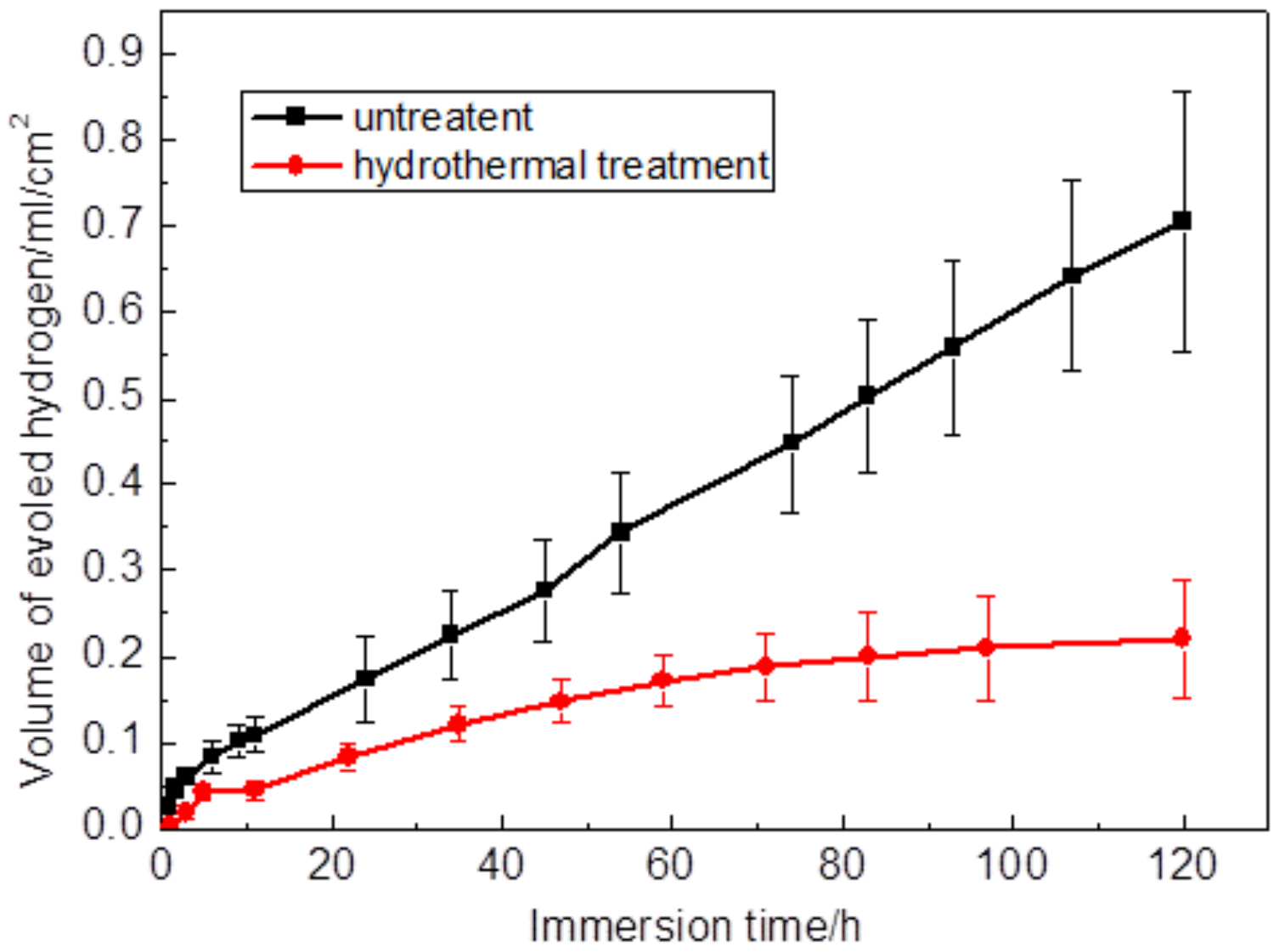
3.5. Immersion Corrosion of Coating

Since the sample HT2 showed satisfactory short-term performance and stability, it was chosen for the long-term performance test in SBF at 37 °C for 5 days. The experiment was conducted as described in the experimental section. The obtained data is shown in the Figure 7. The overall corrosion reaction of Mg at its free corrosion potential can be expressed as follows [33,34]:
Mg   +   2 H 2 O Mg 2 +   +   2 OH   +   H 2
Thus, one mole of the oxidized Mg corresponds to one mole of evolved hydrogen and measuring its volume enables determining of the Mg weight loss. The quantity of the dissolved hydrogen was neglected.
After 120 h the quantity of the evolved hydrogen reached a mark at 0.7 mL/cm2, whereas that of the HT2 was slightly above 0.2 mL/cm2. This proves the fact that the coated sample also shows resistance against corrosion in the course of a long-term corrosive load. The corrosion rate of the untreated sample was constant during the experiment duration of 120 h, while that of the HT2 sample was continuously decreasing. The drop of the corrosion rate in the case of the HT2 may indicate additional surface passivation or local establishment of conditions, which slow down the kinetics of the Mg oxidation. Figure 8a,b shows the HT2 coating morphology after the long-term test. It remained almost unchanged as compared to the freshly prepared sample (Figure 1e,f): the coating is still uniform and compact completely covering the metal surface with no voids or cracks.

4. Conclusions

In the present study, we proposed a simple, fast and effective method of biomedical Mg6Ho0.5Zn alloy protection by means of in-situ hydrothermal growth of protective coating in 0.5 M NaHCO3 at 200 °C. The morphology and the phase composition of such grown coating may be influenced by varying the treatment duration. A thin film mainly consisting of spherical flower-like Mg5(CO3)4(OH)2 · 4H2O particles resulted after 0.5 h of the hydrothermal treatment. Increasing the treatment duration up to 3 h results in a compact thick film consisting of irregular granular MgCO3 as well as some Mg(OH)2. By means of comprehensive evaluation of the mechanical and electrochemical coating properties, the treatment duration of 2 h was found to be the optimum treatment duration. Longer processing leads to deterioration of the coating mechanical properties. The protective coating may slow down the penetration of detrimental anions, such as Cl, thus making the alloy corrode uniformly and slowly in-vivo as well.

Author Contributions

Conceptualization, J.Z. and S.L.; Methodology and Software J.X., Z.L. and L.Z.; Investigation and Data Curation, R.W., L.H. and M.Z.; Writing—Original Draft Preparation, J.X. and L.Z.; Writing—Review and Editing and Supervision, J.Z.

Funding

The research was funded by National Natural Science Foundation of China (No. 51871069), Natural Science Foundation of Heilongjiang Province of China (No. E2017030) and Foundation of State Key Laboratory of Rare Earth Resources Utilization (No. RERU2018017).

Conflicts of Interest

The authors declare no conflict of interest.

References

  1. Zhao, D.; Witte, F.; Lu, F.; Wang, J.; Li, J.; Qin, L. Current status on clinical applications of magnesium-based orthopedic implants: A review from clinical translational perspective. Biomaterials 2017, 112, 287–302. [Google Scholar] [CrossRef] [PubMed]
  2. Husak, Y.; Solodovnyk, O.; Yanovska, A.; Kozik, Y.; Liubchak, I.; Ivchenko, V.; Mishchenko, O.; Zinchenko, Y.; Kuznetsov, V.; Pogorielov, M. Degradation and in vivo response of hydroxyapatite-coated Mg alloy. Coatings 2018, 8, 375. [Google Scholar] [CrossRef]
  3. Tian, P.; Liu, X. Surface modification of biodegradable magnesium and its alloys for biomedical applications. Regen. Biomater. 2015, 2, 135–151. [Google Scholar] [CrossRef] [PubMed]
  4. Sanchez, A.H.M.; Luthringer, B.J.; Feyerabend, F.; Willumeit, R. Mg and Mg alloys: How comparable are in vitro and in vivo corrosion rates: A review. Acta. Biomater. 2015, 13, 16–31. [Google Scholar] [CrossRef] [PubMed]
  5. Han, P.; Cheng, P.; Zhang, S.; Zhao, C.; Ni, J.; Zhang, Y.; Zhong, W.; Hou, P.; Zhang, X.; Zheng, Y.; et al. In vitro and in vivo studies on the degradation of high-purity Mg (99.99 wt.%) screw with femoral intracondylar fractured rabbit model. Biomaterials 2015, 64, 57–69. [Google Scholar] [CrossRef] [PubMed]
  6. Esmaily, M.; Svensson, J.E.; Fajardo, S.; Birbilis, N.; Frankel, G.S.; Virtanen, S.; Arrabal, R.; Thomas, S.; Johansson, L.G. Fundamentals and advances in magnesium alloy corrosion. Prog. Mater. Sci. 2017, 89, 92–193. [Google Scholar] [CrossRef]
  7. Gu, X.N.; Li, S.S.; Li, X.M.; Fan, Y.B. Magnesium based degradable biomaterials: A review. Front. Mater. Sci. 2014, 8, 200–318. [Google Scholar] [CrossRef]
  8. Pan, C.J.; Pang, L.Q.; Hou, Y.; Lin, Y.B.; Gong, T.; Liu, T.; Ye, W.; Ding, H.Y. Improving corrosion resistance and biocompatibility of magnesium alloy by sodium hydroxide and hydrofluoric acid treatments. Appl. Sci. 2016, 7, 33. [Google Scholar] [CrossRef]
  9. Sun, W.; Zhang, G.; Tan, L.; Yang, K.; Ai, H. The fluoride coated AZ31B magnesium alloy improves corrosion resistance and stimulates bone formation in rabbit model. Mater. Sci. Eng. C 2016, 63, 506–511. [Google Scholar] [CrossRef] [PubMed]
  10. Zhou, Y.R.; Zhang, S.; Nie, L.L.; Zhu, Z.J.; Zhang, J.Q.; Cao, F.H.; Zhang, J.X. Electrodeposition and corrosion resistance of Ni–P–TiN composite coating on AZ91D magnesium alloy. Trans. Nonferrous Met. Soc. China 2016, 26, 2976–2987. [Google Scholar] [CrossRef]
  11. Liu, Y.; Xue, J.; Luo, D.; Wang, H.; Gong, X.; Han, Z.; Ren, L. One-step fabrication of biomimetic superhydrophobic surface by electrodeposition on magnesium alloy and its corrosion inhibition. J. Colloid. Interface. Sci. 2017, 491, 313–320. [Google Scholar] [CrossRef] [PubMed]
  12. Badruddoza Dithi, A.; Nezu, T.; Nagano-Takebe, F.; Hasan, M.; Saito, T.; Endo, K. Application of solution plasma surface modification technology to the formation of thin hydroxyapatite film on titanium implants. Coatings 2019, 9, 3. [Google Scholar] [CrossRef]
  13. Liu, J.; Xi, T. Enhanced anti-corrosion ability and biocompatibility of PLGA coatings on Mg–Zn–Y–Nd alloy by BTSE-APTES pre-treatment for cardiovascular stent. J. Mater. Sci. Technol. 2016, 32, 845–857. [Google Scholar] [CrossRef]
  14. Çelik, İ. Structure and surface properties of Al2O3-TiO2 ceramic coated AZ31 magnesium alloy. Ceram. Int. 2016, 42, 13659–13663. [Google Scholar] [CrossRef]
  15. Ji, M.K.; Oh, G.; Kim, J.W.; Park, S.; Yun, K.D.; Bae, J.C.; Lim, H.P. Effects on antibacterial activity and osteoblast viability of non-thermal atmospheric pressure plasma and heat treatments of TiO2 nanotubes. J. Nanosci. Nanotechnol. 2017, 17, 2312–2315. [Google Scholar] [CrossRef] [PubMed]
  16. Jin, W.; Wu, G.; Feng, H.; Wang, W.; Zhang, X.; Chu, P.K. Improvement of corrosion resistance and biocompatibility of rare-earth WE43 magnesium alloy by neodymium self-ion implantation. Corros. Sci. 2015, 94, 142–155. [Google Scholar] [CrossRef]
  17. Cheng, M.; Qiao, Y.; Wang, Q.; Qin, H.; Zhang, X.; Liu, X. Dual ions implantation of zirconium and nitrogen into magnesium alloys for enhanced corrosion resistance, antimicrobial activity and biocompatibility. Colloids. Surf. B Biointerfaces 2016, 148, 200–210. [Google Scholar] [CrossRef] [PubMed]
  18. Wei, Z.; Tian, P.; Liu, X.; Zhou, B. In-vitro, degradation, hemolysis, and cytocompatibility of PEO/PLLA composite coating on biodegradable AZ31 alloy. J. Biomed. Mater. Res. B Appl. Biomater. 2015, 103, 342–354. [Google Scholar] [CrossRef] [PubMed]
  19. Tian, P.; Xu, D.; Liu, X. Mussel-inspired functionalization of PEO/PCL composite coating on a biodegradable AZ31 magnesium alloy. Colloids. Surf. B Biointerfaces 2016, 141, 327–337. [Google Scholar] [CrossRef] [PubMed]
  20. Tian, P.; Liu, X.; Ding, C. In vitro degradation behavior and cytocompatibility of biodegradable AZ31 alloy with PEO/HT composite coating. Colloids. Surf. B Biointerfaces 2015, 128, 44–54. [Google Scholar] [CrossRef] [PubMed]
  21. Dong, K.; Song, Y.; Shan, D.; Han, E.H. Corrosion behavior of a self-sealing pore micro-arc oxidation film on AM60 magnesium alloy. Corros. Sci. 2015, 100, 275–283. [Google Scholar] [CrossRef]
  22. Wu, G.; Gong, L.; Feng, K.; Wu, S.; Zhao, Y.; Chu, P.K. Rapid degradation of biomedical magnesium induced by zinc ion implantation. Mater. Lett. 2011, 65, 661–663. [Google Scholar] [CrossRef]
  23. Amaravathy, P.; Rose, C.; Sathiyanarayanan, S.; Rajendran, N. Evaluation of in vitro bioactivity and MG63 oesteoblast cell response for TiO coated magnesium alloys. J. Sol-Gel. Sci. Technol. 2012, 64, 694–703. [Google Scholar] [CrossRef]
  24. Zhao, J.; Chen, L.J.; Yu, K.; Chen, C.; Dai, Y.L.; Qiao, X.Y.; Yan, Y.; Yu, Z.M. Effects of chitosan coating on biocompatibility of Mg–6%Zn–10%Ca3(PO4)2 implant. Trans. Nonferrous Met. Soc. China 2015, 25, 824–831. [Google Scholar] [CrossRef]
  25. Gu, X.N.; Zheng, W.; Cheng, Y.; Zheng, Y.F. A study on alkaline heat treated Mg–Ca alloy for the control of the biocorrosion rate. Acta Biomater. 2009, 5, 2790–2799. [Google Scholar] [CrossRef] [PubMed]
  26. Zhu, Y.; Wu, G.; Zhang, Y.H.; Zhao, Q. Growth and characterization of Mg(OH)2 film on magnesium alloy AZ31. Appl. Surf. Sci. 2011, 257, 6129–6137. [Google Scholar] [CrossRef]
  27. Peng, F.; Li, H.; Wang, D.; Tian, P.; Tian, Y.; Yuan, G.; Xu, D.; Liu, X. Enhanced corrosion resistance and biocompatibility of magnesium alloy by Mg–Al-layered double hydroxide. ACS. Appl. Mater. Interfaces. 2016, 8, 35033–36044. [Google Scholar] [CrossRef] [PubMed]
  28. Zhang, L.; Zhang, J.; Xu, C.; Jing, Y.; Zhuang, J.; Wu, R.; Zhang, M. Formation of stacking faults for improving the performance of biodegradable Mg–Ho–Zn alloy. Mater. Lett. 2014, 133, 158–162. [Google Scholar] [CrossRef]
  29. Jiao, Y.; Zhang, J.; Kong, P.; Zhang, Z.; Jing, Y.; Zhuang, J.; Wang, W.; Zhang, L.; Xu, C.; Wu, R.; et al. Enhancing the performance of Mg-based implant materials by introducing basal plane stacking faults. J. Mater. Chem. B 2015, 3, 7386–7400. [Google Scholar] [CrossRef]
  30. Dan, S.; Ma, A.B.; Jiang, J.; Lin, P.; Yang, D.; Fan, J. Corrosion behavior of equal-channel-angular-pressed pure magnesium in NaCl aqueous solution. Corros. Sci. 2010, 52, 481–490. [Google Scholar]
  31. Yao, C.; Lv, H.; Zhu, T.; Zheng, W.; Yuan, X.; Gao, W. Effect of Mg content on microstructure and corrosion behavior of hot dipped Zn–Al–Mg coatings. J. Alloys. Compd. 2016, 670, 239–248. [Google Scholar] [CrossRef]
  32. Mosiałek, M.; Mordarski, G.; Nowak, P.; Simka, W.; Nawrat, G.; Hanke, M.; Socha, R.P.; Michalska, J. Phosphate–permanganate conversion coatings on the AZ81 magnesium alloy: SEM, EIS and XPS studies. Surf. Coat. Technol. 2011, 206, 51–62. [Google Scholar] [CrossRef]
  33. Zhou, W.; Shan, D.; Han, E.H.; Ke, W. Structure and formation mechanism of phosphate conversion coating on die-cast AZ91D magnesium alloy. Corros. Sci. 2008, 50, 329–337. [Google Scholar] [CrossRef]
  34. Lu, F.; Ma, A.; Jiang, J.; Guo, Y.; Yang, D.; Song, D.; Chen, J. Significantly improved corrosion resistance of heat-treated Mg–Al–Gd alloy containing profuse needle-like precipitates within grains. Corros. Sci. 2015, 94, 171–178. [Google Scholar] [CrossRef]
Figure 1. SEM micrographs of samples HT0.5 (a,b), HT1 (c,d), HT2 (e,f) and HT3 (g,h) prepared by hydrothermal treatment in 0.5 M NaHCO3 at 200 °C for 0.5, 1, 2 and 3 h respectively.
Coatings 09 00160 g001
Figure 2. XRD patterns of samples HT0.5, HT1, HT2 and HT3 prepared by hydrothermal treatment in 0.5 M NaHCO3 at 200 °C for 0.5, 1, 2 and 3 h respectively.
Coatings 09 00160 g002
Figure 3. (a) SEM micrograph; (b) elemental composition; and (c) cross–section micrograph of the HT2 sample.
Coatings 09 00160 g003
Figure 4. Schematic representation of the suggested coating formation mechanism: (a) nucleation; (b) transformation; (c) densification; (d) overall coating formation mechanism.
Coatings 09 00160 g004
Figure 5. SEM micrographs of the samples HT2 (a,b) and HT3 (c,d) after adhesion test.
Coatings 09 00160 g005
Figure 6. (a) Polarization curves and (b,c) Nyquist plots of untreated samples and samples HT0.5, HT1, HT2 and HT3 prepared by hydrothermal treatment in 0.5 M NaHCO3 at 200 °C for 0.5, 1, 2 and 3 h respectively.
Coatings 09 00160 g006
Figure 7. Amount of evolved hydrogen as function of time for HT2 and an untreated sample.
Coatings 09 00160 g007
Figure 8. SEM micrographs of the samples HT2 (a,b) after static immersion in SBF solution at 37 °C for 5 days.
Coatings 09 00160 g008
Table 1. Composition of the simulated body fluid (SBF).
ComponentMassDegree of Purity [%]
NaCl8.035 g/L99.5
NaHCO30.355 g/L99.5
KCl0.225 g/L99.5
K2HPO4 · 3H2O0.231 g/L99.0
MgCl2 · 6H2O0.311 g/L98.0
C(HCl) = 1 M39 mL
CaCl20.292 g/L95.0
Na2SO40.072 g/L99.0
Tris6.118 g/L99.0
Table 2. Jcorr and Ecorr of the samples HT0.5, HT1, HT2 and HT3.
Hydrothermal Time [h]Jcorr [A/cm2]Ecorr [V]
02.015 × 10⁻⁴−1.793
0.51.114 × 10−4−1.854
16.765 × 10⁻⁵−1.712
22.129 × 10⁻⁵−1.450
32.896 × 10⁻⁵−1.367

