Article

Laser Surface Blasting of Granite Stones Using a Laser Scanning System

1
Department of Applied Physics, University of Vigo, EEI, Lagoas-Marcosende, 36310 Vigo, Spain
2
Department of Materials Engineering, Applied Mechanics and Construction, University of Vigo, EEI, Lagoas-Marcosende, 36310 Vigo, Spain
*
Author to whom correspondence should be addressed.
Coatings 2019, 9(2), 131; https://doi.org/10.3390/coatings9020131
Submission received: 3 December 2018 / Revised: 28 January 2019 / Accepted: 18 February 2019 / Published: 19 February 2019
(This article belongs to the Special Issue Surface Treatment by Laser-Assisted Techniques)

Abstract

:
Granite stones are the most abundant rock of the crust. Due to their beauty, durability, and virtually zero maintenance, they have been used widely since ancient times in all types of construction, as a structural or decorative element. Commonly, this material is used with a polished finishing, but there has been an increased interest in giving it a rustic aspect, mainly for decorative or functional reasons, e.g., to reduce slipping. Rough surfaces are usually produced by means of bush hammering, but this is an extremely noisy and inefficient process. In this work we have explored the capabilities and limits of a laser blasting process assisted by a scanning system in order to produce precise and controllable roughness on two varieties of granite plates. It was found that laser blasting of thin granite tiles can be accomplished with processing widths up to 250 mm at medium-low laser power, obtaining a rustic aspect suitable for use in façades, paving, or flooring. Moreover, laser scanner systems are capable of enhancing the productivity of this process up to ten times greater than that found in previous works.

1. Introduction

Granite stones are one of the most suitable materials for construction due to their beauty, durability, and low maintenance. This is a manifestly crystalline rock with an interlocking structure. Its composition depends on the exact variety of granite, but in general it is mainly composed of feldspar, quartz, a small amount of mica, and minor accessory minerals (such as zircon, apatite, magnetite, ilmenite, or sphene) [1]. These materials have a greater strength than marble, sandstone, or limestone and therefore are more difficult to machine [2].
The international trade of granite was valued at around $2.5 billion in 2016 [3], with an estimated production of 20 million tons. From a commercial point of view, the maximum usage of granite is in paving, internal and external flooring, and façades [4].
Surface finish is one of the major concerns related to the application of natural stones. Different finishes will provide different aesthetic value, durability, or slip resistance. A polished finish is commonly used for internal flooring and tiling, while on the other hand, a rough finish, e.g., a bush hammered finish, is used to create a non-slip surface, ideal for high traffic outdoor areas or to give a rustic aspect employed on feature cladding and cobblestones.
Bush hammering is the most employed technique to give a rough surface finish to granites. It consists of beating the stone using a hammer designed specifically for this application, so some material is removed from the surface. Despite its wide application, it possesses some disadvantages: The level of noise is high (>120 dB), the powder generation is pronounced, the minimum thickness to apply this method is restricted to high values (typically higher than 25 mm), and the cost of the process is increased by the replacement of worn-out tools.
In order to overcome these drawbacks, laser technology seems to be a good choice since it has already demonstrated its capability to treat different building materials such as concrete, natural stones, tiles, and rocks [5]. For example, some authors have focused on surface texturing of concrete by laser scabbling [6,7,8] or in marble [9]. Regarding granite, a polished surface was laser treated to be transformed into a non-slip surface by generating micro-craters [10,11] on it. The laser blasting of granite has been previously reported [12,13], which consisted of material being removed from its surface by a laser beam. Moreover, no mechanical stresses are induced on the plate, so thin tiles can be treated and wasted powder and noise is greatly reduced compared to conventional bush hammering.
Infrared lasers are typically employed for processing granite. The most common are Nd:YAG, diode, and CO2 lasers, but CO lasers are also used [14]. A Nd:YAG laser is commonly utilized for surface treatments [15] and for producing craters [10]. On the other hand, drilling [16] and surface treatment [12,13] are also carried out by a diode laser. However, CO2 lasers are most commonly employed for processing granite. Valente et al. [16] demonstrated that a CO2 laser is more efficient than diode lasers for drilling white granite and it was assumed to be due to a higher absorption. Laser cutting of granite by CO2 laser was recently reported in [17]. Drilling of granite submerged in water [18] and surface treatment [9] has also been carried out by CO2 lasers.
The main limitation of laser technology for surface treatments (and particularly for laser blasting) is related to their difficulty in treating large areas due to the reduced dimensions of the spot size of a focused laser beam. However, the combination of high-power laser sources and scanning systems used in laser treatments, such as laser hardening [19], microstructuring [10], and more recently in laser cladding [20], can overcome the low productivity of laser blasting process.
In the present work, we investigated laser blasting process assisted by scanning systems on two varieties of granite. Therefore, the aim of this work was to present an in-depth study of the influence of the processing parameters (laser power, P, transverse speed (velocity in the Y-direction, v1) and scanning speed (velocity in the X-direction, v2)) on the roughness and quality of the finished surface for non-slip applications, as determined by advanced statistical methods.

2. Materials and Methods

2.1. Materials

The materials used in the experiments were two different granite plates: A white granite (called White Alba granite) and a black granite (a gabbro called Black South Africa granite). Both granites have a medium size grain, are compact, and exhibit an irregular fracture.
Plates of 350 mm × 250 mm × 10 mm and an initial average surface roughness of Ra = 0.22 μm and Ra = 0.068 μm for the white and black granites, respectively, were used in the laser blasting experiments.

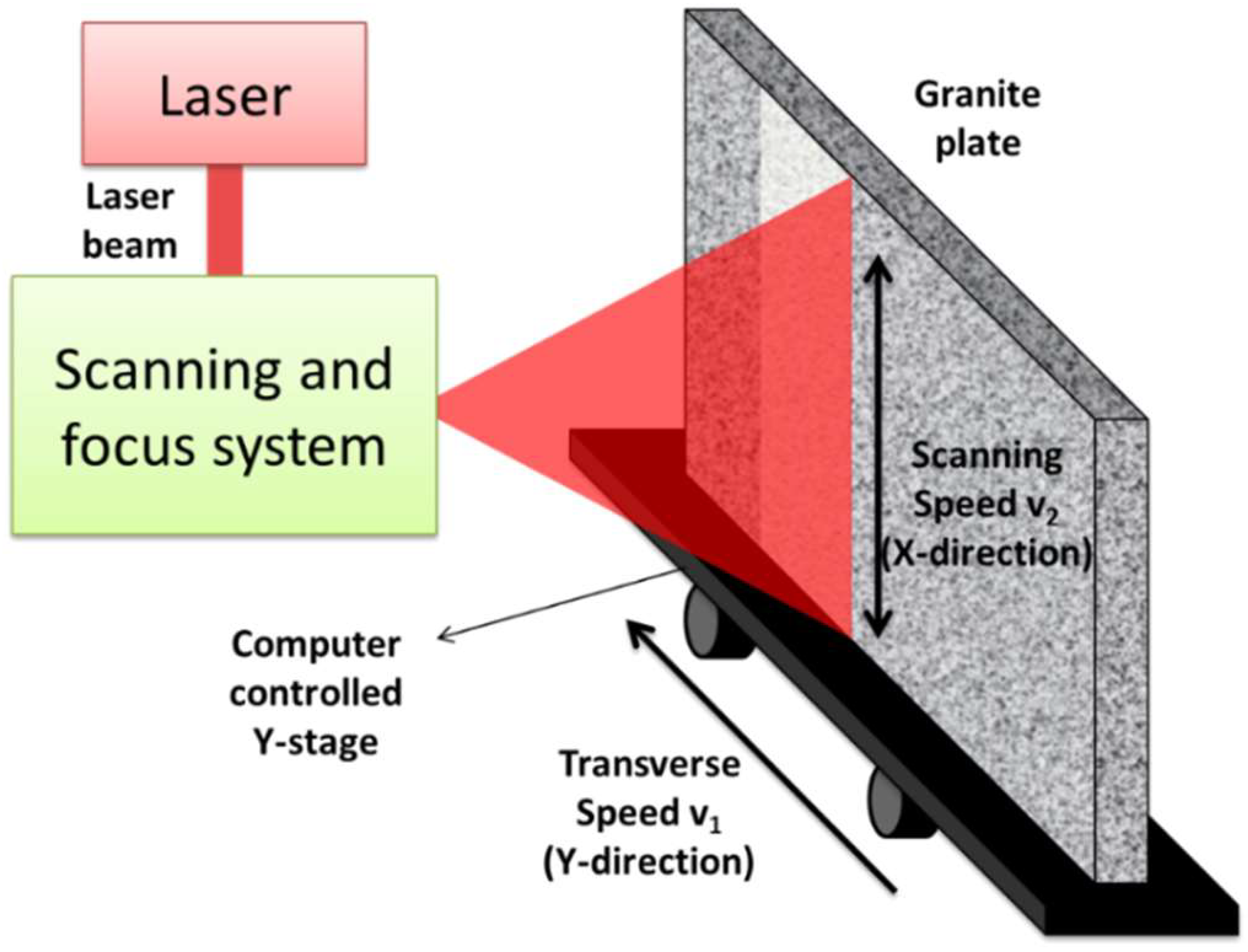
2.2. Experimental Procedures

The laser treatment was performed using a 3.5 kW CO2 slab laser (Rofin-Sinar DC035, Hamburg, Germany), emitting a TEM00 CW laser beam at a 10,600 nm wavelength. The laser beam was focused onto the surface of the sample using a lens with a 710 mm focal length, thus achieving a laser focal spot diameter of 0.56 mm. In order to perform a wide surface treatment, the laser beam was scanned over the sample, in all cases, in air at atmospheric pressure.
Figure 1 shows an illustration of the experimental set-up employed for the laser treatments. To perform a fast and wide surface treatment, a special designed polygon mirror scanner was implemented to produce a high-speed deflection of the laser beam in one direction (e.g., X-direction). On the other hand, the scanned laser beam was moved along a perpendicular direction (e.g., Y-direction) by means of a computer numerically controlled table. Using this scanning system, the laser beam was deflected up to 450 mm in the X-direction along the sample, therefore, tiles were processed in only one pass along the whole X-direction, while the scanned laser beam was moved at a constant rate in the Y-direction.
A full factorial design (FFD) approach was developed to screen out the key variables (laser power, P; transverse speed (velocity in the Y-direction, v1); and scanning speed (velocity in the X-direction, v2) which significantly influence the response variables (average roughness of samples, Ra and a quality factor, Q). Two levels (designated “+” and “−”) for each of the four processing parameters were investigated, as summarized in Table 1. The processing parameters for the full factorial design were selected based on preliminary tests performed at the laboratory (not included here). Only factors with p < 0.05 were considered significant. In a full factorial experiment, responses were measured at all combinations (i.e., conditions at which the responses were measured) of the experimental factor levels. Using an analysis of variance (ANOVA) scheme, those factors having a significant effect on the response variables were identified. Additionally, a regression model was used to estimate the response values as a function of the significant variables. This experimental strategy allowed the determination of the influence of a reduced number of different laser parameter combinations without decreasing the accuracy of the results. Please consult [21] for more details about the mathematical procedure.

2.3. Sample Characterization

Selected samples were inspected in frontal view to the laser treated area by means of an optical stereoscopic microscope (Nikon SMZ-10A, Tokyo, Japan) coupled to a photographic system in order to record and store images.
Roughness was measured by a surface roughness gauge (TESA Rugosurf 10G, Renens, Switzerland) in several locations of the treated areas. Then, an average value for the average roughness (Ra) was extracted to characterize the surface finishing after the laser treatment. Measurements were made in accordance with the recommendations specified by the International Standard ISO 4288:1996 [22].
In order to study the influence of laser radiation on the granite, laser treated and untreated samples of granite were analyzed by Raman spectroscopy. Raman reflection spectra were acquired by means of a spectrometer (Horiba Jobin Yvon LAbRam-HR800, Kyoto, Japan) equipped with an Ar laser excitation source (488 nm) and coupled with a microscope.
Finally, the quality of the laser blasted samples was evaluated by means of a quality factor (designated Q Factor) which takes into account different variables such as: melting of the surface; processing speed; laser power; amount of residue; removed material; roughness; and visual appearance.
Therefore, the following expression was used:
Q = X 0 ( 20 X 1 + 7.5 X 2 + 7.5 X 3 + 5 X 4 + 5 X 5 + 30 X 6 + 25 X 7 )
The possible values for each variable are summarized in Table 2. The importance of each variable was weighted by a factor associated with its relevance on the final application, then, roughness, visual appearance, and detection of notorious melting of the surface were selected as the most relevant parameters determining the quality of samples for its application to produce non-slipping surfaces. On the other hand, the other variables are related with the laser process itself. Therefore, they are less important than the others, but still relevant.

3. Results

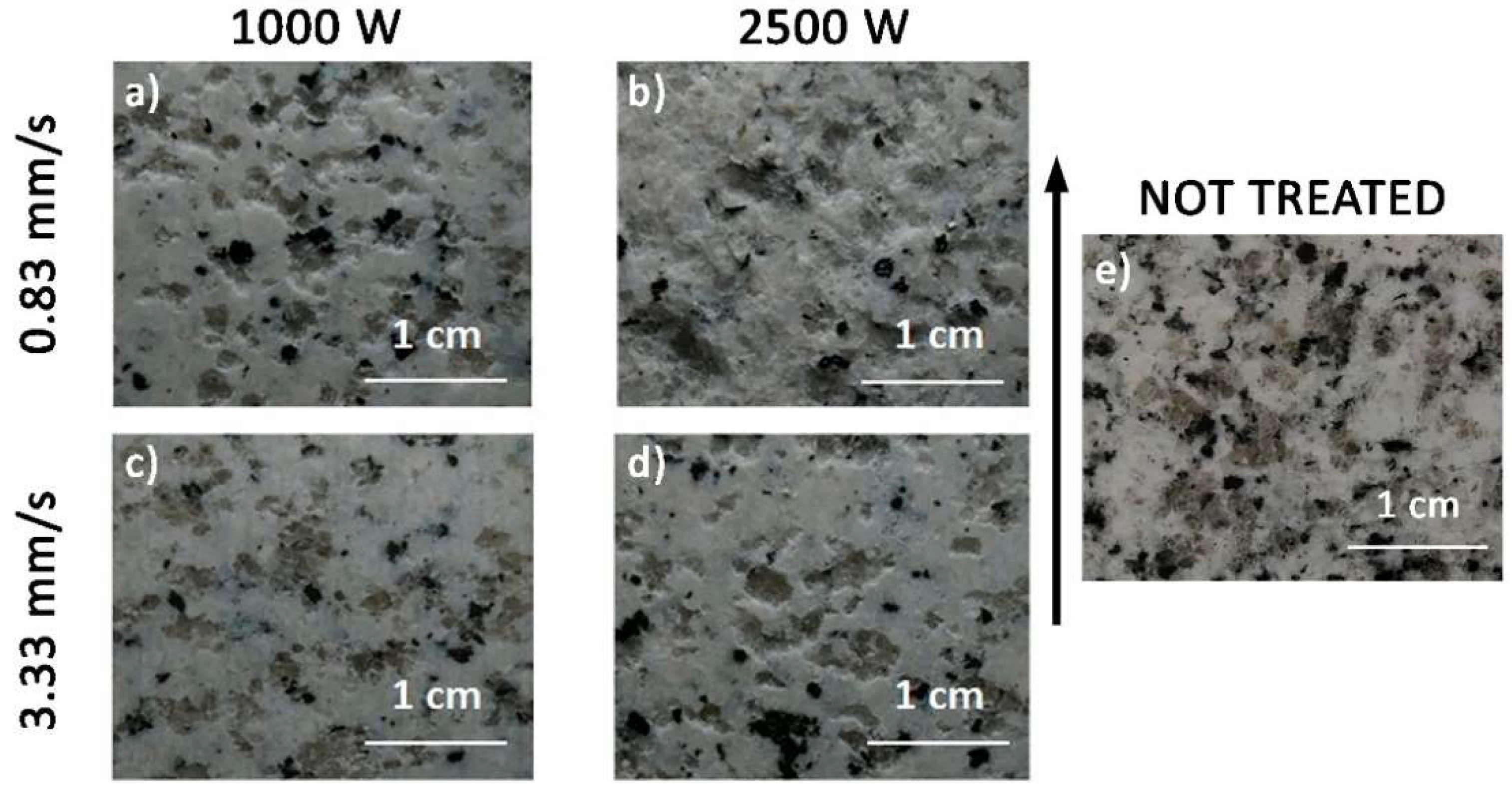
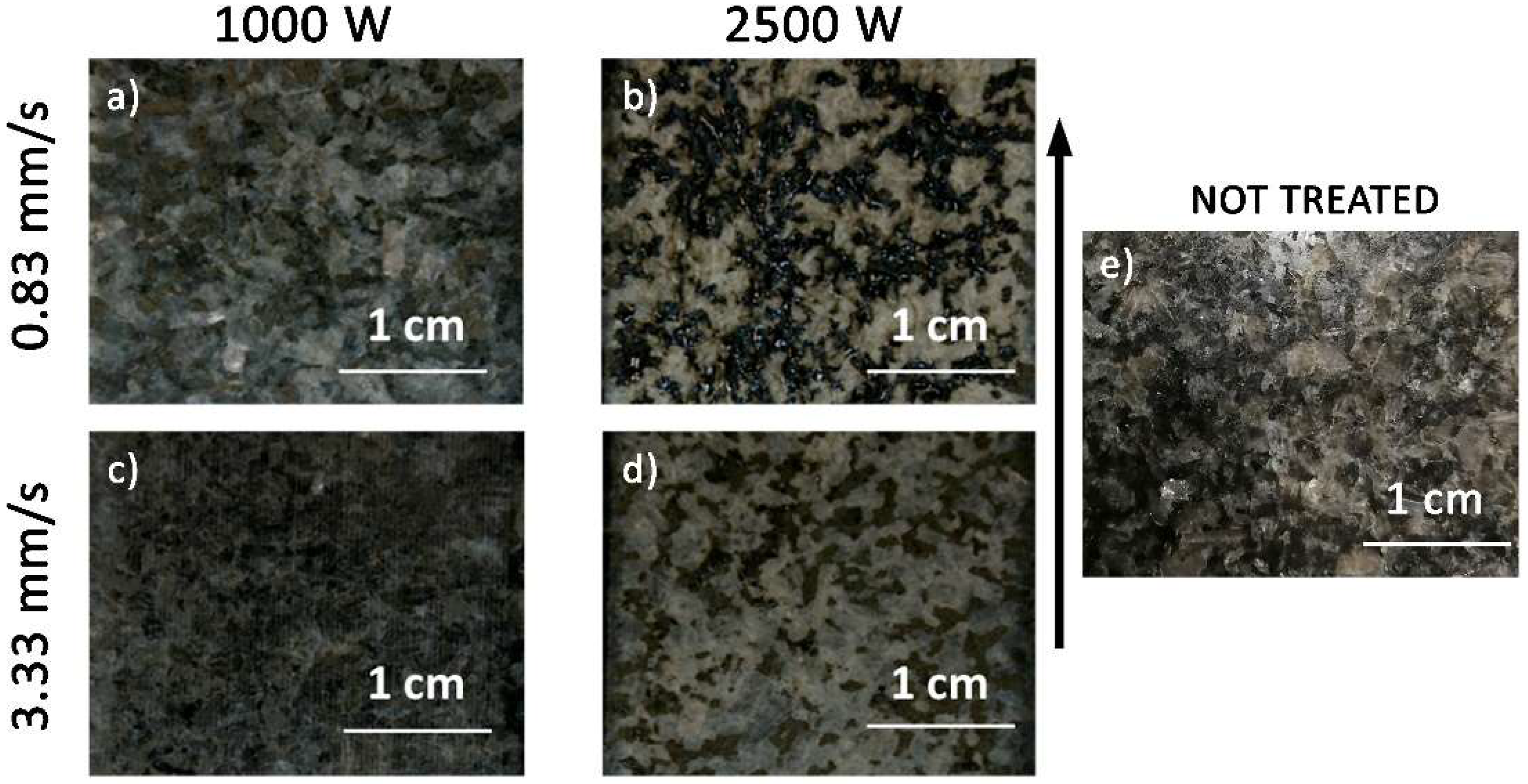
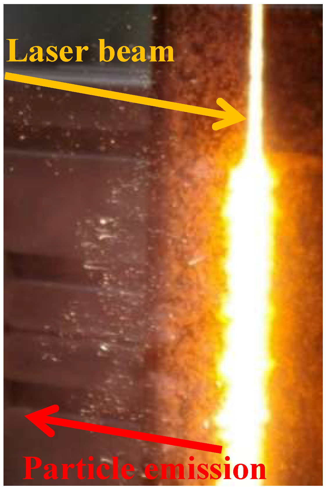
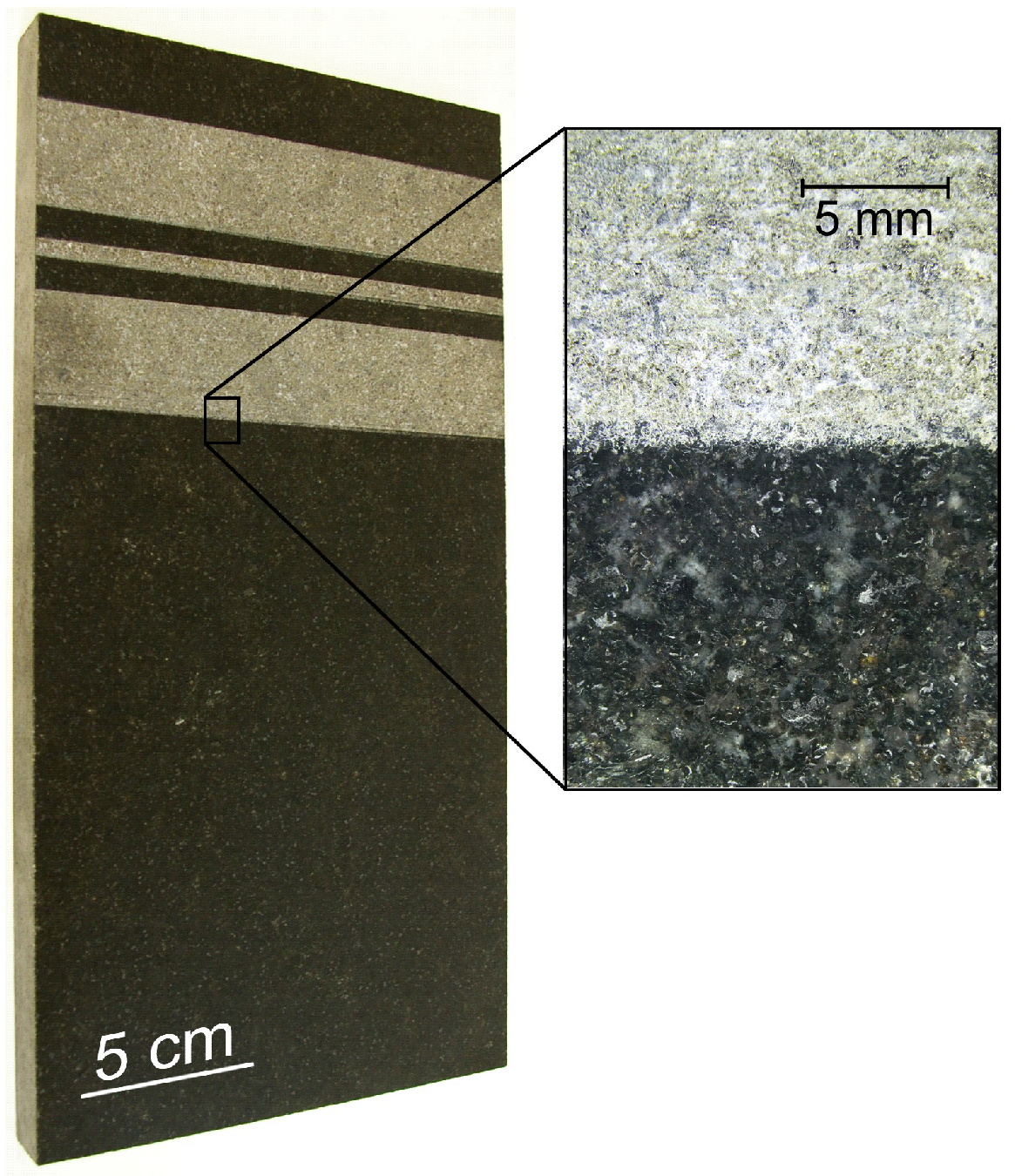
3.1. Processing Results

The utilization of a laser beam in conjunction with a scanning system allows for the treatment of large areas. Processing results indicate that 250 mm in length (x-axis) can be treated in one pass using the experimental setup developed in this work. As seen in Figure 2 and Figure 3, treated surfaces exhibit a homogenous aspect and a rustic aspect. The maximum productivity reached during the experimental tests was around 3 m2/h for both granites. This processing rate is approximately ten times higher as compared to those results found in the literature [12,13]. It should be noted that the working rate using conventional methods, such as a rotary bush hammer, is around 15–20 m2/h. In order to reach and surpass these figures, advantages of laser processing should be exploited, e.g., working in parallel with multiple laser beams or employing high brightness laser sources.
On the other hand, roughness values as high as 20 μm were reached during the processing of both granites. These values are smaller than in the case of conventional methods such as flaming (75 μm) or bush hammering (125 μm).
The interaction of a laser beam with rocks can spall, melt, or vaporize them as the energy transferred to the material raises its temperature locally. Literature data indicate that the most efficient rock removal mechanism is the thermal-spallation due to the lower temperature required as compared to melting or vaporization [23].
The scanning of a laser beam focused onto the surface of both granites, under an average irradiance of 10,960 W/mm2, tends to produce the spallation of the surface, as depicted in Figure 4 for the black granite. This irradiance causes an increment in temperature which can be approximately calculated for a semi-infinite, homogeneous solid [24] by Equation (2):
T ( x ,   y ,   z ,   t ) = T 0 + Q 2 π k x 2 + y 2 + z 2 exp ( v ( w + x 2 + y 2 + z 2 ) 2 α )
where T—temperature; T0—ambient temperature; Q—laser power; v—travel speed of the laser beam; x/y/z—distances in the x, y, and z directions; w—distance in the x direction in a moving coordinate of speed v (w = xvt); α—thermal diffusivity; and k—thermal conductivity.
The increment in the temperature due to the laser scanning produces thermal stresses as given approximately by the well-known equation [25]:
σ x = σ y = E a T 1 ν
where E—Young modulus; a—coefficient of lineal thermal expansion; T—temperature; and ν—Poisson’s ratio.
As seen, thermal stress, and in consequence the spallation, is proportional to the temperature reached in the interaction region. These stresses are quite significant in granites due to their low thermal conductivity and high linear thermal expansions. The spalling/cracking is formed when the thermal stresses beneath the surface reach the tensile strength of the granite [10]. At this stage, flakes or particles are emitted from the surface in a normal direction as seen in Figure 4. It was observed that part of the flakes (up to 1–2 mm in length) can be melted and remain lightly adhered to the surface of the treated area during the processing at high laser powers and low scanning and traverse speeds as depicted in Figure 5.
During the processing of both granites, a slight melting of the surface can be observed. However, this effect is quite selective. Quartz and feldspar tends to be highly fractured, mainly in the white granite, however, mica tends to be essentially melted as corroborated by Raman analyses in processed samples of white granite (Figure 6). As noted, mica (annite) is in a glassy state.
The melting process of mica is quite different in both granites. In the white granite, mica is only slightly melted and tends to form micrometric drops in order to minimize its surface energy (Figure 7a). On the other hand, mica particles in the black granite are massively melted and tend to form large drops, while feldspar and quart tends to bleach (Figure 7b).

3.2. Roughness Results
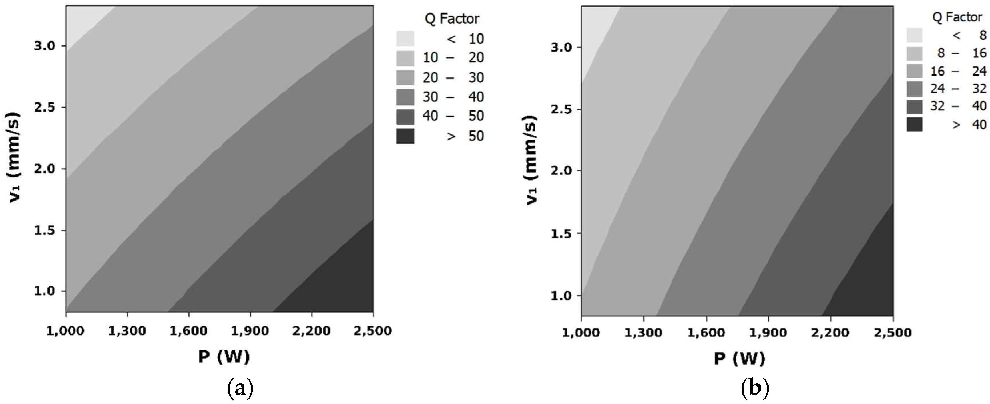
As previously discussed, the appearance of the treated surfaces strongly depends on the processing parameters. The analysis of the full factorial design reveals laser power and transverse speed as the most statistically significant factors affecting the roughness during the processing of both granites. Influence of the scanning speed can be neglected for the range of values studied in this work. The response surfaces for the average roughness have been calculated as:
R a ( μ m ) = 10.72 + 0.0118 P + 5.8375 v 1 + 6.8 × 10 5 v 2   ( White   granite )
R a ( μ m ) = 11.00 + 0.0395 P 3.4152 v 1 7.9 × 10 5 v 2   ( Black   granite )
Only terms up through Order 1 were included in the model for simplicity, and plotted in Figure 8 and Figure 9.
As seen during the processing of both granites, the average roughness of the samples is increased by means of the increment of the laser power and by the reduction of the transverse and scanning speed. The effect of the reduction of the scanning speed is much less compared to the traverse speed. This can be explained under the basis of Equations (2) and (3). Utilization of high laser powers and low speeds produces large temperatures and, in consequence, high thermal stresses. The higher the thermal stresses, the more efficient the laser blasting process, and the sample exhibits a larger roughness.

3.3. Quality Factor

A quality factor was proposed to evaluate the performance of the laser blasting process on the studied materials using the guidelines given in Section 2.3. The results of the full factorial design show that laser power and transverse speed are the statistically significant factors affecting the quality of the blasting. Influence of the scanning speed can be neglected for the range of values studied in this work. The response surfaces for the quality factor have been calculated as:
Q = 23.39 + 0.0168   P 11.11   v 1 + 8.5 × 10 6   v 2   ( White   granite )
Q = 15.26 + 0.0177   P 6.16   v 1 6.17 × 10 5   v 2   ( Black   granite )
Only terms up through Order 1 were included in the model for simplicity and plotted in Figure 10.
The quality obtained during the processing of the black granite is inferior to the quality obtained for the white granite. In both cases, the quality is increased by the increment of the laser power and the decrement of the transverse speed. Evolution of the quality as a function of the processing parameters is quite similar in both granites.
Laser blasting with the scanning system can be also employed in other kind of granites. Figure 11 shows a polished plate of Black Zimbabwe granite with three bands of non-slipping surface. They were made using 1000 W of laser power and 2 mm/s of transverse speed. Therefore, the CO2 laser demonstrated its capability to produce a rustic non-slip surface on different kinds of granites.

4. Conclusions

A laser blasting process assisted by a scanning system has been used to treat the surface of thin granite tiles (10 mm). Using a moderate laser power (1 kW) this system allows blasting the surface of granite plates with processing widths of 250 mm. Processing conditions required to tailor the surface roughness and quality of results were determined using statistical methods. The quality of the laser blasted samples was evaluated by means of a quality factor (designated Q Factor) which takes into account different variables such as: melting of the surface; processing speed; laser power; amount of residue; removed material; roughness; and visual appearance. Laser power and traverse speed were found to be the most relevant processing parameters. Surface quality and roughness are both increased with the laser power and decreased with the traverse speed.
The obtained results show a way to maximize roughness and quality and reveal that the efficiency of the process is up to ten times higher than in prior works found in the literature using lasers.
Comparing to existing mechanical methods for granite blasting, such as bush hammering, the laser blasting process assisted by a scanning system here applied, shows several advantages: the level of noise is almost negligible compared with the 120 dB reached when using mechanical means; the laser blasting process allows blasting granites of just 10 mm, compared to the minimum thickness of 25 mm required to apply the bush hammering method; the amount of powder generated during the bush hammering is much higher than the one produced by the laser blasting technique.
Different kinds of granites (White Alba, Black South Africa and Black Zimbabwe) were successfully treated by means of a high-power CO2 laser assisted by a scanning system, obtaining a rustic appearance surface suitable to be used in façades, paving, or flooring.

Author Contributions

Conceptualization, J.d.V. and J.P. (Juan Pou); Data Curation, J.d.V. and A.R.; Formal Analysis, A.R. and F.Q.; Investigation, J.P. (Joaquín Penide), J.d.V., R.S. and M.B.; Methodology, R.C.; Validation, F.L.; Writing—Original Draft Preparation, J.P. (Joaquín Penide); Writing—Review & Editing, A.R., F.L. and J.P. (Juan Pou).

Funding

This work was partially supported by the Xunta de Galicia (ED431B 2016/042, ED481D 2017/010, and ED481B 2016/047-0).

Acknowledgments

The authors wish to thank the technical staff from CACTI (University of Vigo) for their help with sample characterization and Marcos Nogueiras for technical assistance with the scanner system at early stages of the work. We would especially like to acknowledge Eduardo García from Cupastone for providing the granite samples and for his support along the whole work.

Conflicts of Interest

The authors declare no conflict of interest. The funders had no role in the design of the study; in the collection, analyses, or interpretation of data; in the writing of the manuscript, or in the decision to publish the results.

References

  1. Blatt, H.; Tracy, R.; Owens, B. Petrology: Igneous, Sedimentary, and Metamorphic, 3rd ed.; W. H. Freeman: New York, NY, USA, 2005. [Google Scholar]
  2. Goodman, R.E. Introduction to Rock Mechanics, 2nd ed.; Wiley: New York, NY, USA, 1989. [Google Scholar]
  3. United Nations Comtrade Database. Available online: https://comtrade.un.org/ (accessed on 3 December 2018).
  4. Taylor, H.A. Compendium of World Dimension Stone Data; Marble Institute of America: Oberlin, OH, USA, 2010. [Google Scholar]
  5. Wignarajah, S. New horizons for high power lasers: Applications in civil engineering. In High-Power Lasers in Civil Engineering and Architecture, Proceedings of International Forum on Advanced High Power Lasers & Applications (AHPLA), Osaka, Japan, 1–5 November 1999; Nakai, S., Hackel, L.A., Solomon, W.C., Eds.; SPIE: Bellingham, WA, USA, 2000; pp. 34–44. [Google Scholar] [CrossRef]
  6. Dowden, J.; Lazizi, A.; Johnston, E.; Nicolas, S. A thermoelastic analysis of the laser scabbling of concrete. J. Laser Appl. 2001, 13, 159–166. [Google Scholar] [CrossRef]
  7. Lobo, L.M.; Williams, K.; Johnson, E.P.; Spencer, J.T. Particle size analysis of material removed during CO2 laser scabbling of concrete for filtration design. J. Laser Appl. 2002, 14, 17–23. [Google Scholar] [CrossRef]
  8. Peach, B.; Petkovski, M.; Blackburn, J.; Engelberg, D.L. An experimental investigation of laser scabbling of concrete. Constr. Build. Mater. 2015, 89, 76–89. [Google Scholar] [CrossRef] [Green Version]
  9. Kosyrev, F.K.; Rodin, A.V. Laser destruction and treatment of rocks. In ALT ’01 International Conference on Advanced Laser Technologies, Proceedings of Advanced Laser Technologies (ALT ’01), Constanta, Romania, 11–14 September 2001; Dumitras, D.C., Dinescu, M., Konov, V.I., Eds.; SPIE: Bellingham, WA, USA, 2002; pp. 166–171. [Google Scholar] [CrossRef]
  10. Hauptmann, J.; Wiedemann, G. Laser microstructuring of polished floor tiles. Key Eng. Mater. 2003, 250, 262–267. [Google Scholar] [CrossRef]
  11. Panzner, M.; Lenk, A.; Wiedemann, G.; Hauptmann, J.; Weiss, H.J.; Ruemenapp, T.; Morgenthal, L.; Beyer, E. Laser processing of siliceous materials. In High-Power Laser Ablation III, Proceedings of High-Power Laser Ablation, Santa Fe, NM, USA, 24–28 April 2000; Phipps, C.R., Ed.; SPIE: Bellingham, WA, USA, 2000; pp. 621–634. [Google Scholar] [CrossRef]
  12. Pou, J.; Trillo, C.; Soto, R.; Doval, A.F.; Boutinguiza, M.; Lusquiños, F.; Quintero, F.; Pérez-Amor, M. Laser blasting—A new method for surface treatment of dimension stones. Key Eng. Mater. 2003, 250, 247–252. [Google Scholar] [CrossRef]
  13. Pou, J.; Trillo, C.; Soto, R.; Doval, A.F.; Boutinguiza, M.; Lusquiños, F.; Quintero, F.; Pérez-Amor, M. Surface treatment of granite by high power diode laser. J. Laser Appl. 2003, 15, 261–266. [Google Scholar] [CrossRef]
  14. Bukatyj, V.I.; Perfil’ev, V.O. Effect of laser radiation on granite and marble. Fiz. Khim. Obrab. Mater. 2000, 4, 39–42. [Google Scholar]
  15. Breaban, F.; Coutouly, J.F.; Braud, F.; Deprez, P. Nd:YAG laser beam-material interactions for marking and engraving: Application to alumina and granite. Lasers Eng. 2015, 30, 1–13. [Google Scholar]
  16. Guedes Valente, L.C.; Pérez, M.A.A.; Gouvêa, P.M.P.; Martelli, C.; De Avillez, R.R.; Braga, A.M.B. Energy efficiency of drilling granite and travertine with a CO2 laser and 980 nm diode laser. Appl. Phys. Mater. Sci. Process. 2013, 110, 639–642. [Google Scholar] [CrossRef]
  17. Riveiro, A.; Mejías, A.; Soto, R.; Quintero, F.; Del Val, J.; Boutinguiza, M.; Lusquiños, F.; Pardo, J.; Pou, J. CO2 laser cutting of natural Granite. Opt. Laser Technol. 2016, 76, 19–28. [Google Scholar] [CrossRef]
  18. Kobayashi, T.; Nakamura, M.; Kubo, S.; Ichikawa, M. Drilling a hole in granite submerged in water by use of CO2 laser. J. Pet. Technol. 2010, 62, 48–51. [Google Scholar] [CrossRef]
  19. Lusquiños, F.; Conde, J.C.; Bonss, S.; Riveiro, A.; Quintero, F.; Comesaña, R.; Pou, J. Theoretical and experimental analysis of high power diode laser (HPDL) hardening of AISI 1045 steel. Appl. Surf. Sci. 2007, 254, 948–954. [Google Scholar] [CrossRef]
  20. Nogueiras, M.; Penide, J.; Comesaña, R.; Del Val, J.; Quintero, F.; Boutinguiza, M.; Lusquiños, F.; Pou, J. Feasibility study of wide band laser surface treatment. Phys. Procedia 2013, 41, 356–361. [Google Scholar] [CrossRef]
  21. Montgomery, D.C. Design and Analysis of Experiments, 8th ed.; Wiley: New York, NY, USA, 2012. [Google Scholar]
  22. ISO 4288:1996 Geometrical Product Specifications (GPS)—Surface Texture: Profile Method—Rules and Procedures for the Assessment of Surface Texture; International Organization for Standardization: Geneva, Switzerland, 1996.
  23. Xu, Z.; Reed, C.B.; Konercki, G.; Parker, R.A.; Gahan, B.C.; Batarseh, S.; Graves, R.M.; Figueroa, H.; Skinner, N. Specific energy for pulsed laser rock drilling. J. Laser Appl. 2003, 15, 25–30. [Google Scholar] [CrossRef]
  24. Eagar, T.W.; Tsai, N.S. Temperature fields produced by traveling distributed heat sources. Weld. J. 1983, 62, 346–355. [Google Scholar]
  25. Callister, W.D.; Rethwisch, D.G. Materials Science and Engineering: An Introduction, 8th ed.; Wiley: New York, NY, USA, 2011. [Google Scholar]
Figure 1. Illustration of the experimental set-up.
Coatings 09 00131 g001
Figure 2. Images showing the aspect of the treated white granite as a function of the laser power and the transverse speed (ad). The black arrow indicates the direction of the “fast” scan speed. (e) Image of not treated granite surface.
Coatings 09 00131 g002
Figure 3. Images showing the aspect of the treated black granite as a function of the laser power and the transverse speed (ad). The black arrow indicates the direction of the “fast” scan speed. (e) Image of not treated granite surface.
Coatings 09 00131 g003
Figure 4. Emission of particles from the irradiated surface produced by thermal stresses induced in the black granite.
Coatings 09 00131 g004
Figure 5. Flakes formed during the laser blasting of white granite remain adhered to the surface due to their melting.
Coatings 09 00131 g005
Figure 6. Raman spectrum for the different phases distinguished in the black granite prior and after the laser blasting process.
Coatings 09 00131 g006
Figure 7. Localized melting observed in the (a) white and (b) black granites.
Coatings 09 00131 g007
Figure 8. Contour plot of average roughness Ra (μm) versus (a) laser power (P) and transverse speed (v1), and (b) laser power (P) and scanning speed (v2) during the processing of white granite.
Coatings 09 00131 g008
Figure 9. Contour plot of average roughness Ra (μm) versus (a) laser power (P) and transverse speed (v1), and (b) laser power (P) and scanning speed (v2) during the processing of black granite.
Coatings 09 00131 g009
Figure 10. Quality factor evolution as a function of the laser power (P) and transverse speed (v1) for the processing of the (a) white granite and (b) black granite.
Coatings 09 00131 g010
Figure 11. Image of a plate of Black Zimbabwe granite with three non-slip bands made by laser blasting and a detail of the transition from polished to laser treated surface.
Coatings 09 00131 g011
Table 1. Factors and levels for the 23 full factorial design.
Laser Power, P (W)Transverse Speed, v1 (mm/s)Scanning Speed, v2 (mm/s)
+++
100025000.833.33100,000200,000
Table 2. Possible values of those parameters involved in the definition of the quality of the laser blasted surfaces.
ParametersPossible Values
HighIntermediateLow
Blast (X0)10.50.1
Melting (X1)0.10.51
Processing speed (X2)10.50.1
Processing power (X3)10.50.1
Residues (X4)0.10.51
Removed material (X5)0.10.51
Roughness (X6)10.50.1
Appearance (X7)10.50.1

