Article

Influence of Sealing Treatment on the Corrosion Resistance of PEO Coated Al-Zn-Mg-Cu Alloy in Various Environments

1
National Key Laboratory of Science and Technology for National Defence on High-strength Structural Materials, Central South University, Changsha 410083, China
2
Department of Mechanical and Energy Engineering, Shaoyang University, Shaoyang 422000, China
*
Authors to whom correspondence should be addressed.
Coatings 2019, 9(12), 867; https://doi.org/10.3390/coatings9120867
Submission received: 22 November 2019 / Revised: 10 December 2019 / Accepted: 13 December 2019 / Published: 16 December 2019

Abstract

:
In the present work, a coating was prepared on an Al alloy substrate by plasma electrolytic oxidation (PEO). To seal the micro defects in the oxide scale, a siloxane layer was prepared on the PEO coating by sol gel method. The polymer sealant was synthesized from Tetraethoxy silane (TEOS) and methacryloxy propyl trimethoxyl silane (MPTES). The chemical structure of the polymer was studied by Fourier transform infrared spectroscopy (FTIR). The morphologies and microstructure of the PEO coating and siloxane coating were investigated by scanning electron microscopy (SEM). The results showed that siloxane formed a continuous layer on the surface and effectively sealed the micro defects. The corrosion behavior of the coatings in three different corrosion solutions (NaCl, HCl, and NaOH) was examined by electrochemical impedance spectroscopy and potentiodynamic polarization. The corrosion resistance of the sealed coatings was superior to that of the PEO coating because it prevented the penetration of corrosive solutions. The corrosion resistance of the sealed coatings was found to decrease with increasing electrolyte concentration. The work demonstrated that siloxane sealing may greatly enhance the corrosion resistance of Al-based PEO coating in acidic, neutral, and alkaline environments.

1. Introduction

Aluminum alloys are widely used in many engineering applications due to their superior performance. But in corrosive environments such as humid, acidic, and alkaline environments, aluminum alloys are prone to corrosion [1,2,3,4]. To protect or mitigate corrosion processes, protective coatings are typically applied to metal surfaces. Plasma electrolytic oxidation (PEO) is considered to be an environmentally friendly coating process mainly focused on the improvement of wear [5,6] and corrosion resistance [7,8].
PEO is a complex process that combines the diffusion of elements in electrolyte with electrophoresis, ion transport in discharge channels, and electrochemical oxidation at the metal surface [9,10,11]. In this process, there are inevitable phenomena such as the discharging process, the solidification process, mechanical stresses, and gas evolution. All of these cause micro defects (pores or cracks) in the structure of PEO coatings. Through these defects, corrosive media can easily penetrate the substrate and reduce the corrosion resistance of the coating system. To prevent the infiltration of the corrosion media and enhance the corrosion resistance of the PEO coating, sealing treatment is required.
The most conventional sealing methods are dichromate, nickel acetate, boiling water, and cold nickel fluoride. However, hot water sealing requires high energy consumption, nickel fluoride sealing is expensive, and Cr (VI) used for dichromate sealing is recognized as toxic [12,13,14]. Recently, many green sealing methods have been proposed. A.C. Bouali et al. [15] proposed a novel approach of achieving active corrosion protection by means of layered double hydroxide (LDH) conversion sealing for PEO coatings. Nguyen Van Phuong [16] reported that sealing treatments of the PEO coating on AZ31 Mg alloy in either cerium or phosphate solution can decrease corrosion current density and delay corrosion initiation during the immersion test in 0.5 M NaCl solution. S.V. Gnedenkov et al. [17] showed that using superdispersed polytetrafluoroethylene (PTFE) powder to seal the porous part of the PEO coating significantly improves the anticorrosion properties of magnesium implant in physiological solution. Siloxane based sol-gel sealing on an anodized aluminum coating was also studied to improve the corrosion resistance. Whelan et al. [18] formed a silane-based sol-gel sealing layer on anodized aluminum and indicated that the sol-gel sealer prepared from organically modified silane showed significantly better corrosion performance than the purely inorganic systems. Wojciechowski et al. [19] found that Al–O–Si covalent bonds were created due to the condensation reaction between the anodized aluminum and silane compounds, and the silane coating showed the best anti-corrosion properties. However, the corrosion resistance of the siloxane sealed PEO coatings in different corrosion solution has not been reported yet.
In the present work, the PEO coatings were prepared in electrolyte of silicate systems on the MAO240H-IV AC power equipment and sealed with siloxane polymer. The siloxane polymer had been synthesized from Tetraethoxysiloxane (TEOS) and methacryloxy propyl trimethoxyl siloxane (MPTES). Using sol-gel technique, siloxane polymer was coated on the PEO coating to form a composite coating on an Al-based alloy. The influence of the siloxane layer on the corrosion behavior of this coating in various environments (acidic, neutral, and alkaline solutions) was investigated by electrochemical experiments. Sealing treatment can effectively improve the corrosion resistance of PEO coatings in different corrosion solutions, thus verifying the effectiveness of siloxane sealants in different corrosion solutions and expanding its application scope.

2. Experimental Procedures

2.1. Materials

An Al–Zn–Mg–Cu alloy was used in this study. The composition of this alloy is listed in Table 1. The samples were shaped as a plate with dimensions of 50 mm × 50 mm × 2 mm. The surface of the samples was ground with up to 1200 grit SiC abrasive papers, cleaned with distil water and methanol, and then dried with flowing hot air prior to PEO treatment.

2.2. Preparation of the PEO Coating

The PEO coatings were prepared in 10 g/L Na2SiO3, 7.5 g/L Na3PO4 and 6 g/L NaOH solution in the MAO240H-IV AC power. The parameters were as follows: Voltage, 560 V; frequency, 650 Hz; duty cycle, 17%; and pulse width, 307 µs. The current varied with oxidizing duration during the PEO process. The electrolyte temperature was maintained below 35 °C by a cooling water circulation system. The treatment time was 15 min.

2.3. Sealing Treatment

The following process was used for sealing the PEO coating in this paper. First, 40 mL of tetraethoxy silane (TEOS) solution in 60 mL of ethanol was stirred at 25 °C for 10 min. Then, 12 mL of methacryloxy propyl trimethoxyl silane (MPTES) and nitric acid (the mass fraction was about 68%, analytically pure) were added to obtain the desired PH value (3.5). The mixture solution was stirred at 25 °C for 45 min. Lastly, 10 mL of distilled water was added; the mixture was stirred at 25 °C for 24 h and aged above 72 h before use. The PEO samples were put into the obtained mixtures for 1 min and cured in an oven in a vertical position at 80 °C for 40 min. (All of the solutions were purchased from Aladdin Industrial Corporation (Shanghai, China) and were used without further modification.)

2.4. Characterization Analysis of the Coatings

The surface and cross-section morphologies of the specimens were observed by SEM (Serion 200 and Quanta-200, Thermo Fisher Scientific, Waltham, MA, USA) with an accelerating voltage of 20 kV. The distribution of chemical elements on the coating was analyzed by the accessory EDS analysis of SEM.
Siemens X-ray diffract meter D5000 (Cu kα radiation) was used to identify the phase constitution of the PEO coating. The X-ray generator settings were 36 kV and 30 mA with a scan speed of 4°/min and a scan range from 20° to 80° (in 2θ).
The chemical structure of the siloxane layer was studied by Fourier transform infrared spectroscopy (FTIR). FTIR spectra were collected on a Nicolet 6700 spectrometer (Thermo Fisher Scientific). For carrying out this test, samples were ground and amalgamated with dry IR-grade KBr in a mortar to form pellets.

2.5. Electrochemical Measurements

The electrochemical experiments were performed in HCl, NaCl, and NaOH solution at 25 °C. A MULTI AUTOLAB M204 electrochemical workstation (Metrohm, Herisau, Switzerland) was used to collect the potentiodynamic polarization curves and electrochemical impedance spectroscopy (EIS) spectra. The electrochemical test consisted of a three-electrode electrochemical cell; the coated samples were used as the working electrode, the counter electrode was a platinum plate, and the reference electrode was a saturated calomel electrode (SCE). The area of the working electrode was 1 cm2. Before starting all electrochemical measurements, all samples were immersed for 30 min to keep the open circuit potential almost constant.
A scanning rate of 0.2 mv/s was applied for potentiodynamic polarisation measurements to study the corrosion potential and corrosion current density. The EIS measurements were carried out over a frequency of 105–10−2 Hz, and the applied sinusoidal signal amplitude was 10 mV. Three parallel experiments were prepared for each coating, and the middle one among the three obtained curves was selected.

3. Results and Discussion

3.1. Formation Mechanism of Siloxane Layer

According to the hydrolysis and condensation reaction, MPTES and TEOS could form a continuous siloxane layer on the surface of the PEO coating by sol-gel treatment. The hydrolysis and condensation processes are indicated in Scheme 1 [20,21]. Under the promotion of nitric acid, Si–OH bonds were formed in the hydrolysis reaction between alkoxy groups (Si–O–CH2CH3) and water molecules. After hydrolysis, a network of siloxane (Si–O–Si) bonds formed in the subsequent condensation reaction between Si–OH or between the Si–OH and Si–O–R [22,23].
Figure 1 depicts the FTIR spectra of the siloxane layer. The peak of the OH group in the vicinity of 3400 cm−1 indicated that MPTES and TEOS had a hydrolysis reaction [24,25]. The subsequent peaks at 2960 and 2929 cm−1 could be assigned to –CH3 (asymmetric stretching) and CH2– (asymmetric stretching) groups [25]. In the low-frequency region, the peaks at 1739.5 and 1701 cm−1 could be attributed to the –COO stretching vibration and symmetrically stretched vibration, respectively, and the peak at 1637.58 cm−1 could be the C=C-stretching vibration from MPTES [26,27]. Additionally, the characteristic absorption bands for Si–O–Si appeared at 1058 and 787 cm−1, indicating that the condensation reaction occurred between MPTES and TEOS [25,28]. The peak at 937 cm−1 showed that there were a few Si–O–CH2CH3 groups that remained [22,29].

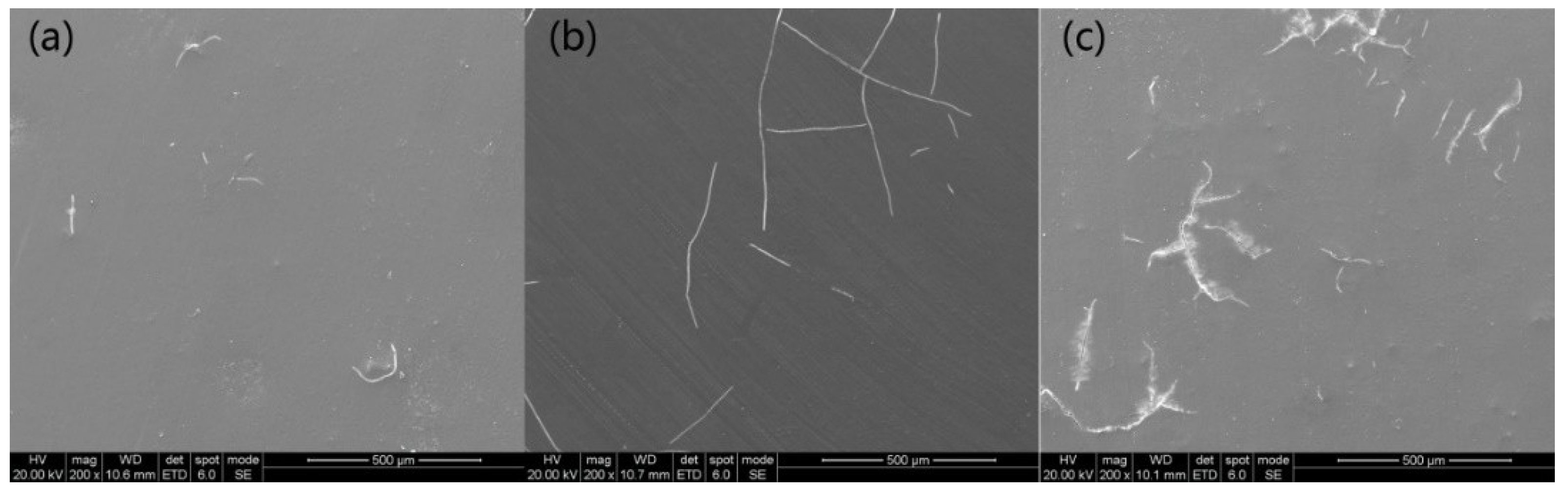
3.2. Morphologies of the Coatings

Figure 2 shows XRD spectra of the PEO coating. It shows that the coating on the sample was mainly composed of γ-Al2O3 phases; no peaks of α-Al2O3 were found in the coating. The appearance of strong peaks of aluminum are attributed to the penetration of X-rays into the substrate due to the porous structure of the PEO coating. Figure 3a shows the SEM surface image of the PEO coating. Many micro pores could be observed on the coating surface. From the cross-section morphology in Figure 3c, there was a porous region at the substrate/coating interface, thus the corrosive mediums could easily penetrate into the substrate/coating interface.
Figure 3b shows the surface of the PEO sample with siloxane sealing. The micro defects were sealed by the siloxane layer completely. According to the cross-sectional morphology (as shown in Figure 3d), the siloxane coating was tightly bonded to the PEO coating. The thickness of the siloxane coating was about 5 µm. After the siloxane layer was removed, the silicon elements filled to the micro pores, as shown in Figure 4, indicating that the siloxane coating had a good sealing effect on the PEO coating.

3.3. Electrochemical Corrosion Behaviour

The corrosion resistance of the PEO samples with and without siloxane sealing in different corrosion solution was studied by potentiodynamic polarization and electrochemical impedance spectroscopy (EIS) plots.

3.3.1. Potentiodynamic Polarization Analysis

Figure 5 represents the potentiodynamic polarization curves of the PEO samples with and without siloxane sealing in three corrosion solutions. The corrosion potential (Ecorr), current densities (icorr), anodic/cathodic Tafel slopes (βα and βc), polarization resistance (Rp), and corrosion rate (νcorr) were calculated using the special analysis software of Metrohm Autolab Nova electrochemical work station. The test results are listed in Table 2.
According to Figure 5 and Table 2, in the same corrosion solution, the icorr of the PEO coating with siloxane sealing were lower than the unsealed one. It was about two orders lower in the 1 M HCl solution, three orders lower in the 0.3 M NaCl solution, and nearly two orders lower in the 0.05 M NaOH solution. Meanwhile, the Ecorr of the PEO coating with siloxane sealing were more positive, and the Rp were greater. The reason for this change is that the micro defects of the PEO coating were sealed by siloxane polymer sealant, which greatly reduced the current density of the sealing coating. Figure 6 displays the surface morphologies of the coatings after a potentiodynamic polarization test in 1 M HCl solution. As shown in Figure 6a,b, the coating without sealing was obviously corroded after the dynamic polarization measurement, and obvious corrosion pits appeared on the surface of some large micro pores, as indicated by the arrow in Figure 6a. For the siloxane sealing PEO coating, only some micro cracks appeared on the siloxane layer, and the coating remained intact, as shown in Figure 6c,d. This suggests that the siloxane sealing PEO coating provided better corrosion resistance, especially in acid and alkaline solutions; the corrosion rate decreased about 100 times.
In addition, due to changes in pH and Cl ion concentration in the corrosion solution [3,4], the icorr of the siloxane sealing PEO coating increased, and the Ecorr and Rp decreased, as the concentration of the solution increased. The reason for this change is that the corrosion solution passed through the micro defects of the siloxane layer, causing the layer to crack. The corrosive medium diffused to the interior of the crack, increasing the corrosion current density. As shown in Figure 7, in HCl solution, the number of cracks increased with the corrosion concentration increase, and staggered cracks even appeared, which shows that, as the concentration of the HCl solution increased, the corrosion damage became more serious. A similar situation also occurred in the other two corrosion solutions.
The corrosion performance of the siloxane sealing PEO coating in different corrosion solutions was found to decrease in the following order:
NaOH > HCl > NaCl

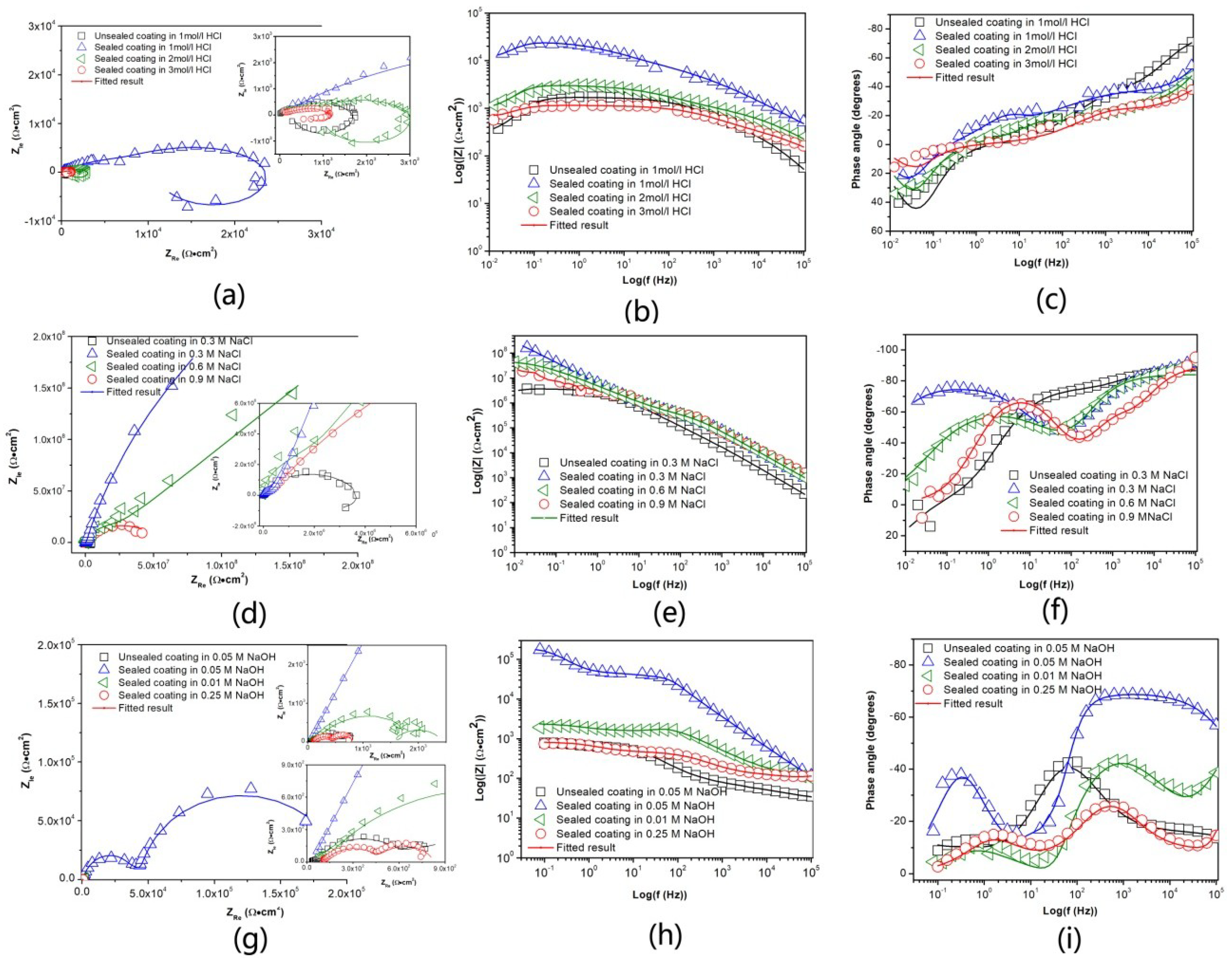
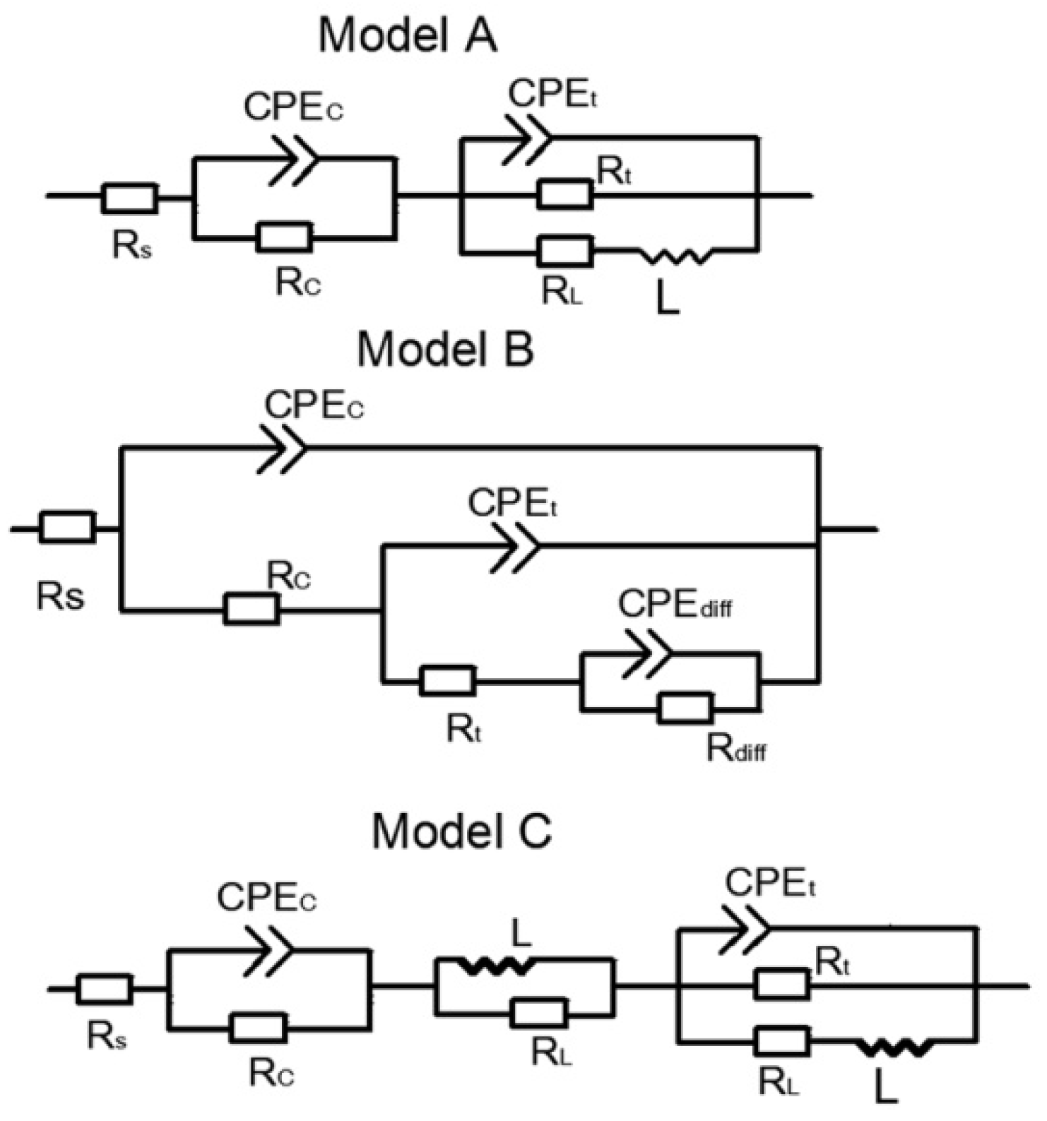
3.3.2. Electrochemical Impedance Spectroscopy (EIS) Analysis

The EIS spectra of the PEO coating with and without siloxane sealing in different corrosion solution are displaed in Figure 8.
In the same corrosion solution, the capacitive loop radius and low frequency impedance (Zlf) values (as shown in the Nyquist and Bode plots in Figure 8) of the siloxane sealing coating were much larger than those of the unsealed one. Zlf can be employed to directly evaluate the corrosion performance of coated samples [30,31,32]. Zlf of samples in different corrosion solutions are listed in Table 3. The Zlf value of the PEO coating with siloxane sealing increased from 1113 to 22,000 Ω·cm2 in the 1M HCl solution, 3.4 × 10⁶ to 1.9 × 10⁷ Ω·cm2 in the 0.3 M NaCl solution, and 851 to 1.74 × 10⁵ Ω·cm2 in the 0.05 M NaOH solution. For the siloxane sealing PEO coatings, the impedance spectra were similar in the same corrosion solution, as shown in Figure 8. However, with the change of pH and Cl ions concentration, the radius of the capacitive loop in the Nyquist diagram was reduced, the Zlf decreased, and the phase angle also decreased as the concentration of the solution increased.
To further analyze the impedance data, the EIS plots were analyzed by Zview software (Zview version: 3.1). Due to surface heterogeneity, roughness, current, and potential distributions associated with electrode geometry, constant phase elements (CPEs) were used to substitute for the capacitances in the equivalent circuit fitting procedure. Based on goodness of fit (the relative standard error within 10% (error % < 10%), or the sum of the squares of the residuals is in the order of 10−3), three typical equivalent circuits were proposed, as shown in Figure 9. Here, Rs, Rc, Rt, and Rdiff represent solution resistance, electrolyte resistance in the coatings, charge transfer resistance, and diffusion resistance, respectively. CPEc, CPEt, and CPEdiff stand for coating capacitance, double-layer capacitance, and diffusion capacitance, respectively. RL and L represent the inductive elements corresponding to the inductive loop. The impedance of CPE is defined as [33,34]:
Z CPE = 1 Y 0 ( j ω ) n
where “Y0” is the CPE constant, “ω” is the angular frequency, “j” is the imaginary number, and “n” is the CPE power. The values of capacitances, Cc and Ct, were calculated from the following equations [35]:
C c = Y 0 1 n ( 1 R s + 1 R c ) ( n 1 ) n
C dl = Y 0 1 n ( 1 R s + 1 R t ) ( n 1 ) n
As shown in Figure 8a–c, the EIS of the unsealed PEO coating in HCl solution consists of three loops; (i) a first capacitive loop at high frequencies (HFs), (ii) a second capacitive loop at intermediate frequencies (IFs), and (iii) an inductive loop at low frequencies (LFs). The appearance of two capacitive loops indicated that the corrosive medium passed through the surface of the coating. The micro defects in the coating were a relatively “occlusion” region, and the mass transfer process became difficult when the active ions in the solution diffused to the defects in the coating. Therefore, the EIS showed a capacitive loop at IFs. For the large inductive loop at LFs, it originated from the disturbance induced by the redissolution of the oxide layer [36,37]. Model A in Figure 9 could well fit the EIS. In the equivalent circuits, for the sealed PEO coatings, the EIS also consisted of three loops in the HCl solution. Taking account of the sealing effect of the siloxane layer, the first capacitive loop at HFs belongs to the siloxane layer. Model A also could well fit the EIS.
In the NaCl solution, Model A could well fit the EIS of the unsealed PEO coating, as shown in Figure 7d,e,f. However, the EIS of the siloxane sealing coating changed a lot; the inductive loop disappeared. Model B was introduced to fit the experiment data. Owing to the strong blocking effect of the saline coating, the capacitive arc could not be observed in the Nyquist plots, as shown in Figure 8d.
In NaOH solution, Model C with nine circuit element was proposed to fit the data. An inductive loop caused by dissolution of alumina appears at an intermediate frequency, suggesting that the corrosion ions had reached the PEO coating/substrate interface, and a corrosion reaction had taken place, leading to the foaming and falling off of the siloxane layer and PEO coating. The other two capacitive loops belong to the siloxane layer and the PEO coating, respectively.
All the fitted EIS spectra based on the equivalent circuits are shown in Figure 8 as the solid lines. The fitted results for typical electrical parameters are listed in Table 4. Cc is considered to be related to the water resistance of the coatings and Rc represents the total resistance of the electrolyte in the micro pores or capillary channels [30]. Rt and Ct measure the total number of active sites for electrochemical corrosion reactions at the metal/electrolyte interface, reflecting the development of a double-layer at the metal/electrolyte interface and the progress of the corrosion reaction [35]. Lower Cc, Ct and higher Rc, Rt values indicate the better corrosion resistance of the coating.
According to Table 4, compared with PEO coating, the Cc, Ct values of the siloxane sealing PEO coating decreased, and Rc, Rt increased significantly. For the siloxane sealing PEO coating, with the increase of the concentration of the corrosive solution, the values of Cc, Ct decreased significantly, and the values of Rc, Rt increased, especially in the NaOH solution.
It can be concluded that the corrosion resistance of the siloxane sealing PEO coating was superior to that of the PEO coating, and the corrosion resistance of the siloxane sealing PEO coatings decreased with increasing concentration of the corrosion medium. These results agreed well with the previous results of the potentiodynamic polarization test.

4. Conclusions

(1)
The PEO coating formed on an Al–Zn–Mg–Cu alloy had many micro defects, such as pores and cracks. The coating was easily permeated by electrolyte and reduced corrosion resistance.
(2)
A silane polymer sealant was synthesized from MPTES and TEOS, effectively filling these micro defects and forming a continuous siloxane layer on the PEO coating by sol-gel technology.
(3)
Compared to the unsealed PEO coating, the corrosion resistance of the PEO coating sealed with siloxane was significantly improved in acidic, neutral, and alkaline environments due to the sealing effect of the siloxane layer. The corrosion resistance of the sealed coatings was found to decrease with increasing electrolyte concentration.

Author Contributions

Conceptualization, D.Z. and Z.L.; Data Curation, D.Z. and J.W.; Formal Analysis, D.Z.; Funding Acquisition, Z.L.; Investigation, D.Z.; Methodology, D.Z.; Project Administration, Z.L. and S.B.; Software, D.Z. and J.W.; Supervision, D.Z.; Validation, D.Z.; Writing–Original Draft, D.Z.; Writing–Review and Editing, D.Z., Z.L. and S.B. All authors have read and agreed to the published version of the manuscript.

Funding

This research was funded by the National Key Research and Development Program of China (2016YFB0300900), the National Key Fundamental Research Project of China (2012CB619506–3), the Natural Science Foundation of China (51171209), and the 2011 Program of Ministry of Education of China.

Acknowledgments

The authors are grateful for financial support from the National Key Research and Development Program of China (2016YFB0300900), the National Key Fundamental Research Project of China (2012CB619506–3), Natural Science Foundation of China (51171209), 2011 Program of Ministry of Education of China.

Conflicts of Interest

There are no conflicts of interest to declare.

References

  1. Priputen, P.; Palcut, M.; Babinec, M.; Mišík, J.; Černičková, I.; Janovec, J. Correlation between Microstructure and Corrosion Behavior of Near-Equilibrium Al-Co Alloys in Various Environments. J. Mater. Eng. Perform. 2017, 26, 3970–3976. [Google Scholar] [CrossRef]
  2. Palcut, M.; Priputen, P.; Kusý, M.; Janovec, J. Corrosion behaviour of Al–29at%Co alloy in aqueous NaCl. Corros. Sci. 2013, 75, 461–466. [Google Scholar] [CrossRef]
  3. Palcut, M.; Ďuriška, L.; Špoták, M.; Vrbovský, M.; Gerhátová, Ž.; Černičková, I.; Janovec, J. Electrochemical corrosion of Al-Pd alloys in HCl and NaOH solution. J. Min. Metall. Sect. B 2017, 53, 333–340. [Google Scholar] [CrossRef] [Green Version]
  4. Ma, J.; Wen, J.; Li, Q.; Zhang, Q. Electrochemical polarization and corrosion behavior of Al–Zn–In based alloy in acidity and alkalinity solutions. Int. J. Hydrog. Energy 2013, 38, 14896–14902. [Google Scholar] [CrossRef]
  5. Javidi, M.; Fadaee, H. Plasma electrolytic oxidation of 2024-T3 aluminum alloy and investigation on microstructure and wear behavior. Appl. Surf. Sci. 2013, 286, 212–219. [Google Scholar] [CrossRef]
  6. Arrabal, R.; Mohedano, M.; Matykina, E.; Pardo, A.; Mingo, B.; Merino, M.C. Characterization and wear behaviour of PEO coatings on 6082-T6 aluminium alloy with incorporated α-Al2O3 particles. Surf. Coat. Technol. 2015, 269, 64–73. [Google Scholar] [CrossRef]
  7. Dehnavi, V.; Shoesmith, D.W.; Luan, B.L.; Yari, M.; Liu, X.Y.; Rohani, S. Corrosion properties of plasma electrolytic oxidation coatings on an aluminium alloy-The effect of the PEO process stage. Mater. Chem. Phys. 2015, 161, 49–58. [Google Scholar] [CrossRef]
  8. Fadaee, H.; Javidi, M. Investigation on the corrosion behaviour and microstructure of 2024-T3 Al alloy treated via plasma electrolytic oxidation. J. Alloy. Compd. 2014, 604, 36–42. [Google Scholar] [CrossRef]
  9. Matykina, E.; Arrabal, R.; Mohamed, A.; Skeldon, P.; Thompson, G.E. Plasma electrolytic oxidation of pre-anodized aluminium. Corros. Sci. 2009, 51, 2897–2905. [Google Scholar] [CrossRef]
  10. Hussein, R.O.; Northwood, D.O.; Nie, X. Processing microstructure relationships in the plasma electrolytic oxidation (PEO) coating of a magnesium alloy. Mater. Sci. Appl. 2014, 5, 124–139. [Google Scholar] [CrossRef] [Green Version]
  11. Martin, J.; Leone, P.; Nomine, A.; Veys-Renaux, D.; Henrion, G.; Belmonte, T. Influence of electrolyte ageing on the Plasma Electrolytic Oxidation of aluminium. Surf. Coat. Technol. 2015, 269, 36–46. [Google Scholar] [CrossRef]
  12. Hu, N.; Dong, X.; He, X.; Browning, J.F.; Schaefer, D.W. Effect of sealing on the morphology of anodized aluminum oxide. Corros. Sci. 2015, 97, 17–24. [Google Scholar] [CrossRef] [Green Version]
  13. Lee, J.; Kim, Y.; Jang, H.; Chung, W. Cr2O3 sealing of anodized aluminum alloy by heat treatment. Surf. Coat. Technol. 2014, 243, 34–38. [Google Scholar] [CrossRef]
  14. Shahzad, M.; Chaussumier, M.; Chieragatti, R.; Mabru, C.; Rezai-Aria, F. Effect of sealed anodic film on fatigue performance of 2214-T6 aluminum alloy. Surf. Coat. Technol. 2012, 206, 2733–2739. [Google Scholar] [CrossRef] [Green Version]
  15. Bouali, A.C.; Straumal, E.A.; Serdechnova, M.; Wieland, D.C.F.; Starykevich, M.; Blawert, C.; Hammel, J.U.; Lermontov, S.A.; Ferreira, M.G.S.; Zheludkevich, M.L. Layered double hydroxide based active corrosion protective sealing of plasma electrolytic oxidation/sol-gel composite coating on AA2024. Appl. Surf. Sci. 2019, 494, 829–840. [Google Scholar] [CrossRef]
  16. Van Phuong, N.; Fazal, B.R.; Moon, S. Cerium- and phosphate-based sealing treatments of PEO coated AZ31 Mg alloy. Surf. Coat. Technol. 2017, 309, 86–95. [Google Scholar] [CrossRef]
  17. Gnedenkov, S.V.; Sinebryukhov, S.L.; Zavidnaya, A.G.; Egorkin, V.S.; Mashtalyar, D.V.; Sergienko, V.I.; Yerokhin, A.L.; Matthews, A. Composite hydroxyapatite–PTFE coatings on Mg–Mn–Ce alloy for resorbable implant applications via a plasma electrolytic oxidation-based route. J. Taiwan. Inst. Chem. E 2014, 45, 3104–3109. [Google Scholar] [CrossRef]
  18. Whelan, M.; Cassidy, J.; Duffy, B. Sol-gel sealing characteristics for corrosion resistance of anodised aluminium. Surf. Coat. Technol. 2013, 235, 86–96. [Google Scholar] [CrossRef]
  19. Wojciechowski, J.; Szubert, K.; Peipmann, R.; Fritz, M.; Schmidt, U.; Bund, A.; Lota, G. Anti-corrosive properties of siloxane coatings deposited on anodised aluminium. Electrochim. Acta 2016, 220, 1–10. [Google Scholar] [CrossRef]
  20. Alyamac, E.; Gu, H.; Soucek, M.D.; Qiub, S.; Buchheit, R.G. Alkoxysi-lane oligomer modified epoxide primers. Prog. Org. Coat. 2012, 74, 67–81. [Google Scholar] [CrossRef]
  21. Matˇejka, L.; Strachota, A.; Plestil, J.; Whelan, P.; Syeinhart, M.; Slouf, M. Epoxy networks reinforced with polyhedral oligomeric silsesquiox-anes (POSS) Structure and morphology. Macromolecules 2004, 37, 9449–9450. [Google Scholar] [CrossRef]
  22. Hu, J.M.; Liu, L.; Zhang, J.Q.; Cao, C.N. Electro deposition of siloxane films on aluminum alloys for corrosion protection. Prog.Org. Coat. 2007, 58, 265–271. [Google Scholar] [CrossRef]
  23. Chruściel, J.J.; Leśniak, E. Modification of epoxy resins with functional siloxanes, polysiloxanes, silsesquioxanes, silica and silicates. Prog. Polym. Sci. 2015, 41, 67–121. [Google Scholar] [CrossRef]
  24. Jothi, K.J.; Palanivelu, K. Synergistic effect of siloxane modified nano-composites for active corrosion protection. Ceram. Int. 2013, 39, 7619–7625. [Google Scholar] [CrossRef]
  25. Pena-Alonso, R.; Rubio, F.; Rubio, J.; Oteo, J.L. Study of the hydrolysis and condensation of γ-aminopropyltriethoxysiloxane by FT-IR spectroscopy. J. Mater. Sci. 2007, 42, 595–603. [Google Scholar] [CrossRef]
  26. Liu, Q.; Kang, Z.X. One-step electrodeposition process to fabricate superhydrophobic surface with improved anticorrosion property on magnesium alloy. Mater. Lett. 2014, 137, 210–213. [Google Scholar] [CrossRef]
  27. Han, M.; Go, S.; Ahn, Y. Fabrication of super-hydrophobic surface on magnesium substrate by chemical etching. Bull. Korean Chem. Soc. 2012, 33, 1363–1366. [Google Scholar] [CrossRef] [Green Version]
  28. Bakhshandeh, E.; Jannesari, A.; Ranjbar, Z.; Sobhani, S.; Saeb, M.R. Anti-corrosion hybrid coatings based on epoxy–silicanano-composites: Toward relationship between the morphologyand EIS data. Prog. Org. Coat. 2014, 77, 1169–1183. [Google Scholar] [CrossRef]
  29. Jiang, H.; Zheng, Z.; Wang, X. Kinetic study of methyltriethoxysiloxane (MTES) hydrolysis by FTIR spectroscopy under different temperatures and solvents. Vib. Spectrosc. 2008, 46, 1–7. [Google Scholar] [CrossRef]
  30. Jiang, M.Y.; Wu, L.K.; Hu, J.M.; Zhang, J.Q. Silane-incorporated epoxy coatings on aluminum alloy (AA2024). Part 1: Improved corrosion performance. Corros. Sci. 2015, 92, 118–126. [Google Scholar]
  31. Bierwagen, G.; Tallman, D.; Li, J.P.; He, L.Y.; Jeffcoate, C. EIS studies of coated metals in accelerated exposure. Prog. Org. Coat. 2003, 46, 148–157. [Google Scholar] [CrossRef]
  32. Touzain, S.; le Thu, Q.; Bonnet, G. Evaluation of thick organic coatings degradation in seawater using cathodic protection and thermally accelerated tests. Prog. Org. Coat. 2005, 52, 311–319. [Google Scholar] [CrossRef]
  33. Wen, L.; Wang, Y.; Zhou, Y.; Ouyang, J.H.; Guo, L.; Jia, D. Corrosion evaluation of microarc oxidation coatings formed on 2024 aluminum alloy. Corros. Sci. 2010, 52, 2687–2696. [Google Scholar] [CrossRef]
  34. Shen, D.; He, D.; Liu, F.; Guo, C.; Cai, J.; Li, G.; Ma, H. Effects of ultrasound on the evolution of plasma electrolytic oxidation process on 6061Al alloy. Ultrasonics 2014, 54, 1065–1070. [Google Scholar] [CrossRef]
  35. Yuan, X.; Yue, Z.F.; Chen, X.; Wen, S.F.; Li, L.; Feng, T. The protective and adhesion properties of silicone-epoxy hybrid coatings on 2024 Al-alloy with a silane film as pretreatment. Corros. Sci. 2016, 104, 84–97. [Google Scholar] [CrossRef]
  36. Beaufort, L.; Benvenuti, F.; Noels, A.F. Iron (II)–ethylene polymerization catalysts bearing 2,6-bis(imino)pyrazine ligands: Part I. Synthesis and characterization. J. Mol. Catal. A Chem. 2006, 260, 210–214. [Google Scholar] [CrossRef]
  37. El Rehim, S.S.A.; Hassan, H.H.; Amin, M.A. Corrosion inhibition of aluminum by 1,1 (lauryl amido) propyl ammonium chloride in HCl solution. Mater. Chem. Phys. 2001, 70, 64–72. [Google Scholar] [CrossRef]
Scheme 1. Hydrolysis - condensation reactions of MPTES and TEOS.
Coatings 09 00867 sch001
Figure 1. FTIR spectra of the sealing layer.
Coatings 09 00867 g001
Figure 2. XRD patterns of the plasma electrolytic oxidation (PEO) coating on the Al-Zn-Mg-Cu alloy.
Coatings 09 00867 g002
Figure 3. (a) Surface morphology of PEO coating; (b) Surface morphology of siloxane sealing coating; (c) cross section morphology of PEO coating; (d) cross section morphology of siloxane sealing coating.
Coatings 09 00867 g003
Figure 4. (a) Surface morphology of siloxane sealing PEO coating after removing the siloxane layer; (b,c) the mixed elemental dot map of (a).
Coatings 09 00867 g004
Figure 5. Potentiodynamic polarization curves of unsealed and sealed coatings: (a) in HCl solution; (b) in NaCl solution; (c) in NaOH solution.
Coatings 09 00867 g005
Figure 6. Surface morphologies of the coatings after the potentiodynamic polarization test in 1 M HCl solution: (a) PEO coating; (b) High magnification morphology for the selected area of (a); (c) Sealed PEO coating; (d) High magnification morphology for the selected area of (c).
Coatings 09 00867 g006
Figure 7. Surface morphologies of the Sealed PEO coating after the potentiodynamic polarization test in (a) 1M HCl solution; (b) 2M HCl solution; (c) 3M HCl solution.
Coatings 09 00867 g007
Figure 8. Electrochemical Impedance Spectroscopy (EIS) plots for the coatings in different corrosion solution: (ac) Nyquist and Bode plots in HCL, (df) Nyquist and Bode plots in NaCl, (gi) Nyquist and Bode plots in NaOH.
Coatings 09 00867 g008
Figure 9. Proposed equivalent circuit models to conduct curve fitting for the EIS data. (CPEc, CPEt, and CPEdiff stand for coating capacitance, double-layer capacitance, and diffusion capacitance, respectively).
Coatings 09 00867 g009
Table 1. Chemical composition of investigated alloys (mass fraction, %).
ZnMgCuCrFeSiAl
6.282.191.60.150.4–0.60.4–0.6Bal.
Table 2. Corrosion dynamics parameters of samples in different solutions.
SampleCorrosion SolutionEcorr (Vvs SCE)icorr (A/cm²)βα (mV/decade)βc (mV/decade)Rp (Ω)νcorr (mm/year)
In HCl
Unsealed coating1 M−0.701.36 × 10−40.070.421302.32
Sealed coating 1 M−0.686.30 × 10−60.110.4259960.073
Sealed coating2 M−0.726.27 × 10−50.430.5216360.72
Sealed coating3 M−0.752.60 × 10−40.830.233043.02
In NaCl
Unsealed coating0.3 M−0.668.33 × 10−80.041.12.7 × 105 9.7 × 10⁻⁴
Sealed coating 0.3 M−0.454.54 × 10−110.010.331.1 × 106 2.4 × 10⁻⁵
Sealed coating0.6 M−0.718.41 × 10−100.020.459.7 × 106 3.2 × 10⁻⁵
Sealed coating0.9 M−0.662.73 × 10−90.0020.443.4 × 105 4.4 × 10⁻⁵
In NaOH
Unsealed coating0.05 M−1.453.08 × 10−40.250.14 1253.58
Sealed coating 0.05 M−1.362.83 × 10−60.260.13 1.3×1040.033
Sealed coating0.1 M−1.381.45 × 10−40.300.17 3061.78
Sealed coating0.25 M−1.404.35 × 10−30.750.26 3428.5
Table 3. The low-frequency impedance (Zlf, at 0.1 Hz) of samples in different solution.
SamplesCorrosion Solution|Zlf0.1Hz| (Ω·cm2)
In HCl
Unsealed coating1 M1113
Sealed coating 1 M2.2 × 105
Sealed coating2 M2488
Sealed coating3 M1041
In NaCl
Unsealed coating0.3 M3.4 × 106
Sealed coating 0.3 M1.9 × 107
Sealed coating0.6 M6.2 × 107
Sealed coating0.9 M4.24 × 107
In NaOH
Unsealed coating0.05 M851
Sealed coating 0.05 M1.74 × 105
Sealed coating0.1M2348
Sealed coating0.25 M810
Table 4. The fitted results of EIS data simulations for samples in HCL solution.
SamplesCorrosion Solution Rc (Ω·cm2)Cc (F·cm−2)Rt (Ω·cm2)Ct (F·cm−2)
In HCl
Unsealed coating1 M2706.3 × 10−814499.6 × 10−5
Sealed coating 1 M1.16 × 1049.4 × 10−101.36 × 1041.6 × 10−7
Sealed coating2 M9672.9 × 10−921185.4 × 10−7
Sealed coating3 M5615.5 × 10−8587.62.8 × 10−6
In NaCl
Unsealed coating0.3 M8.3 × 1046.8 × 10−93.6 × 1061.4 × 10−10
Sealed coating 0.3 M4.1 × 1061.2 × 10−92.4 × 1088.8 × 10−12
Sealed coating0.6 M2.1 × 1062.4 × 10−91.9 × 1082.7 × 10−10
Sealed coating0.9 M4.4 × 1058.4 × 10−95.4 × 1071.32 × 10−9
In NaOH
Unsealed coating0.05 M2.3 × 1046.6 × 10−64011.7 × 10−5
Sealed coating 0.05 M3.4 × 1059.2 × 10−93.1 × 1045.3 × 10−8
Sealed coating0.1 M24681.9 × 10−810047.9 × 10−7
Sealed coating0. 25 M11753.4 × 10−71052.7 × 10−6

