1. Introduction
Modern rhinoplasty involves restoring both the external appearance of the nose and the functionality. Both procedures are equally important and for this, all functional abnormalities of the nose should be corrected in the same surgical procedure. The lateral nasal osteotomy is performed almost in all rhinoplasties.
To elucidate critical information for the biomechanics of the nose several researchers resort to FEM (Finite Element Method) analysis as a powerful modeling tool. Different surgical procedures, in the field of rhinoplasty, can be found in literature [
1,
2,
3,
4,
5,
6]. For instance, Huang et al. [
1,
2] had simulated the surgical correction of cleft lip nasal deformity and the cleft lip rhinoplasty procedure in terms of stresses developed on several parts of the nose. FEM was also employed for modelling of the nasal septum with a view to facilitating the proper septal realignment and reconstruction [
3]. FE analyses (FEA) of certain deformities of nose such as the inverted-V and the support of the nasal tip [
4,
5,
6] were also reported.
Nevertheless, the lateral nasal osteotomy which constitutes a key step in almost all surgical procedures in rhinoplasty, has not been simulated yet by FEA methodologies. Due to this lack in literature, the main motivation of this study was to establish a FEA-based methodology so as to simulate the lateral nasal osteotomy surgical procedure. The main underlying goal was to determine the stress distributions and deformations in the surgical instrument (osteotome) used, so as to predict the wear status of the instrument. Osteotomes, as a bone-cutting instruments applied in osteotomies during nasal bone surgical operations, are subjected to repetitive impact loads leading to a sudden and unexpected fatigue failure during their usage. As a result, worn osteotome replacement during a surgical operation is necessary, affecting the smooth handling of the scheduled surgical procedures and risking leaving a metal fragment in the patient and thus disturbing the good postoperative course of the patient.
It should be mentioned that FEM analysis of surgical instruments used in rhinoplasty has been given little attention by researchers, in contrast to the biomechanical analysis of the nose. Ghassemi et al. [
7] have compared a diamond instrument with a curved osteotome for performing a lateral nasal osteotomy in a clinical study. However, there was no accompanying FEM study, whereas the quality of the osteotomy was checked only visually. Experimental studies on the quality of the osteotomes in terms of sharpness have been reported [
8,
9] but again without any FE analysis of the surgical procedures.
In summary, this work aims at developing a FEA-based methodology in order to predict the osteotome wear status during lateral nasal bone surgery. In this context, a FEA model was developed using ANSYS software in order to simulate dynamically the osteotome penetration into the nasal bone. The dependence upon the accumulated number of impacts’ fatigue strength was a variable parameter in the developed FEA-model. To simulate the crack formation and propagation in both materials (osteotome and nasal bone), it is presumed that the developed von Mises stresses have to exceed the maximum fatigue stress limit. For the osteotome material examined, the latter parameter (fatigue stress limit) was experimentally determined by conducting perpendicular impact tests supported by appropriate FEM calculations [
10,
11]. Based on the developed methodology, the critical number of impacts for a preventive replacement of the osteotome before its extensive fracture can be determined. The latter depends upon the osteotome material properties and geometry. A depiction of fracture patterns in both the osteotome and nasal bone is also feasible by the employment of this FEA-supported methodology.
2. Materials and Methods
2.1. Lateral Nasal Osteotomy Surgical Procedure to be Modelled by FEM
Traditional methods of performing osteotomies rely on making low, symmetrical lateral bony cuts along the nasal bone. To perform a lateral nasal osteotomy two techniques are commonly used by surgeons, the internal continuous osteotomy (linear technique) and the external perforating osteotomy. The latter method results in extensive edema and significant injury of the nasal mucosa [
12]. Therefore, the preferred method of most surgeons is internal continuous osteotomy and was thus chosen to be modeled by FEM for this study.
The surgical maneuvers, when performing an internal continuous lateral osteotomy follow a certain pattern (learning curve) [
13].
Figure 1 shows the different curves for such a lateral nasal osteotomies (low-to-low, low-to-high, high-to-low-to-high), along with a schematic representation of a continuous (internal) lateral nasal osteotomy. The most widely accepted path of the internal continuous lateral osteotomy follows a low-to-low pathway. Although this approach is standard, it should be mentioned that the selection of osteotomy type is evaluated individually for every patient [
13]. The osteotome is used to perform a transnasally (continuous) bony cut, creating a single fracture along the lateral portion of the nasal bones.
Therefore, as a case study, the virtual cut of the nasal bone in the FE model was planned by performing a low-to-low lateral osteotomy. A straight osteotome was chosen as the surgical instrument. The nasal bone has a small thickness (ca. 0.25mm) and is a very fragile bone. Therefore, during the lateral osteotomy, the instrument is placed vertical to the thickness of the nasal bone (
Figure 1) and repetitive impacts are exercised on the osteotome by the surgeon using a special mallet resulting in a progressive bone fracture.
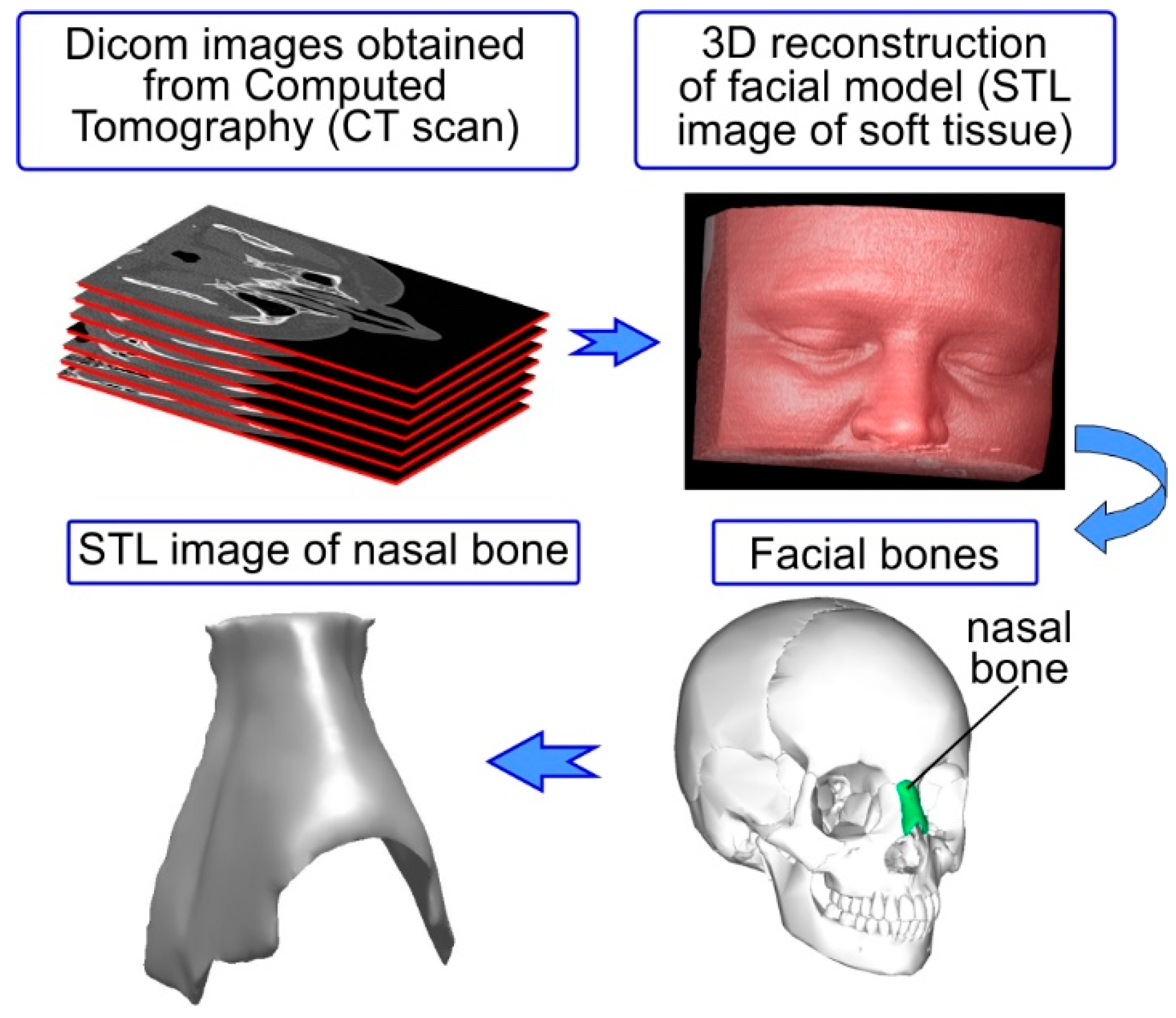
For simulating this procedure precisely, it is necessary to have the actual geometry of the nasal bone depicting the critical features such as bone thickness and bony nasal pyramid projection. In
Figure 2 schematic representation of the methodology followed in this study for accurately simulating the lateral osteotomy is depicted. The first step was to accurately capture the nose geometrical features in order to have a realistic nasal bone model. This was achieved by using a computed tomography (CT) scan. Subsequently, the geometry of the osteotome was appropriately measured to capture critical characteristic of the cutting edge of the instrument and designed in a 3D CAD (Computer Aided Design)-software (Autodesk Inventor 2017). The osteotome’s material properties were necessary as input data for the FE model. This information was attained after conducting experiments using an impact tester to obtain the Woehler diagram of the material, depicting the fatigue stress limits of the osteotome. Appropriate boundary conditions were applied in the FE model of the osteotome and nasal bone (which are discussed in detail in the subsequent sections). The results obtained, allowed the visual depiction of von Mises stress fields and the fracture patterns of both the osteotome and the nasal bone. Finally, the validation of the FEM-calculated results was performed by comparison with experimental results and clinical data for the osteotome.
2.2. Construction of Nasal Bone Model
A high-resolution, maxillofacial, computed tomography scan of a single adult female patient was used to generate the soft-tissue and bone reconstructions of the nasal model using image processing software (InVesalius 3.1.1). To attain this target, dicom images obtained by computed tomography of a human head were used (see
Figure 3). A medical CT Scanner (AQUILION 16 manufactured by Toshiba) was used. The entire head was sliced at 0.6-mm intervals. Standard and approved clinical techniques were used to obtain the desired CT scan.
The 3D geometrical model of the nasal bone was created through computer-based image reconstruction. More specifically, the dicom images (around 160 dicom images which were compiled into a 3D stack) were segmented to distinguish between the nasal bone and the rest of the facial model (soft tissue). This segmentation function used the image’s (dicom file) gray-scale range to create boundaries (adaptive segmentation technique). The polarity rule was applied in boundary topology to indicate which part was included and which part was excluded. The next step, after the segmentation of the images and the creation of appropriate boundary conditions, was the digital stacking of the dicom images so as to create a 3D geometrical volume of the nasal bone for visualization, measurements, and quantitative analysis (see
Figure 3). In this step the 3D-geometrical depiction of the nasal bone can be derived by connecting the boundaries from all image slices. A polygon-based 3D geometrical depiction can thus be created (STL (Stereolithography) file from the defined object boundaries). This polygon based 3D model was comprised of faces in form of triangles and polygons. Each triangular face had 3 points (x, y, z) for the 3 corners thus creating a set of points (point cloud) which can be connected with each other to form a triangulated mesh. This polygonal-based 3D surface model of the nasal bone served only for qualitative analysis and visual depiction.
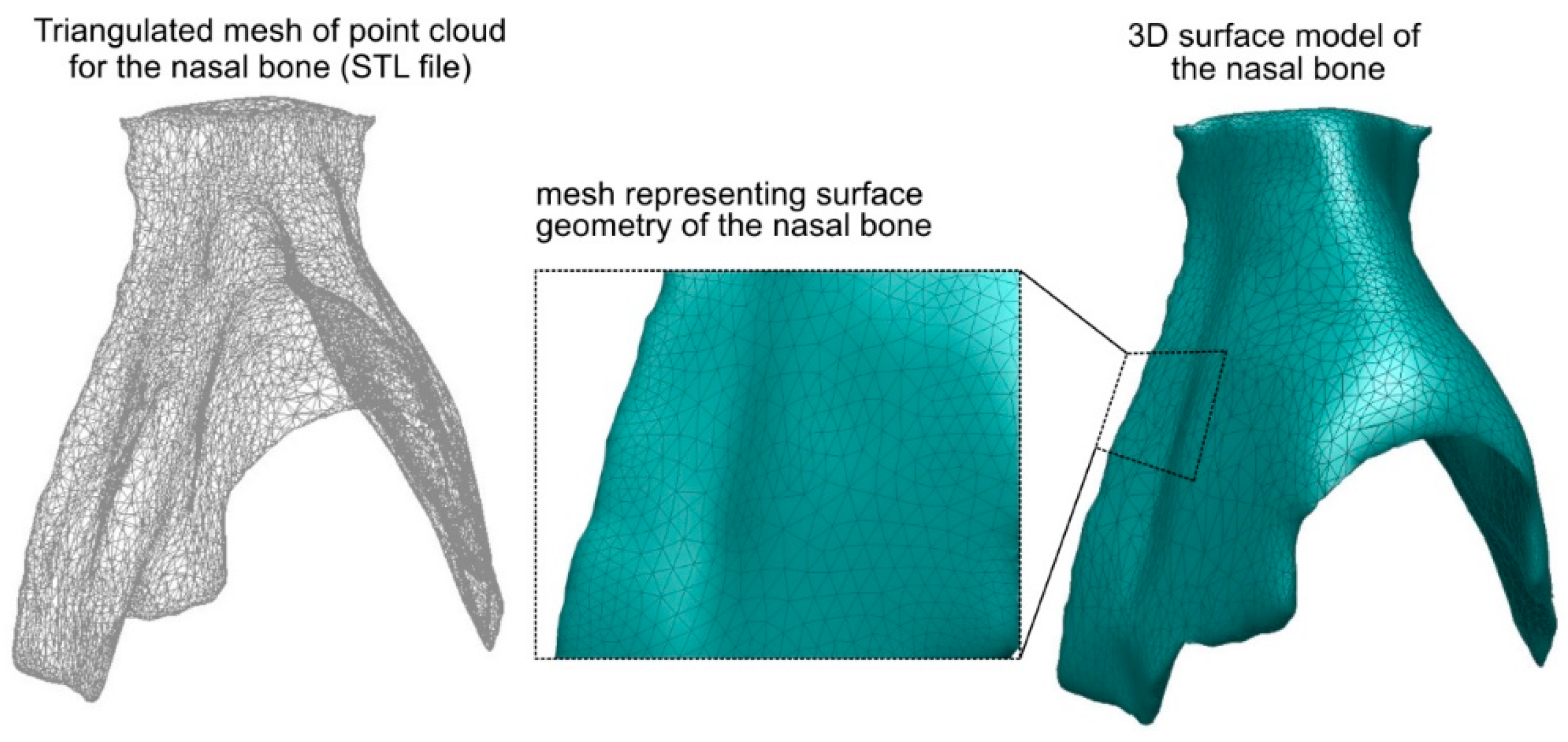
The next step was to create the 3D-surface of the nasal bone in order to insert it in the FEA model (see
Figure 4). For this reason the STL file was processed (Autodesk Meshmixer) to control the final number of triangular faces and therefore reduce the file size. The goal was to simplify and smooth the 3D geometrical model of the nasal bone while simultaneously retaining a high degree of resolution, i.e., keeping the 3D geometry of the model as close as possible to the original. It should be mentioned that the 3D digital images, depicted in the STL file, cannot be directly imported in most of the commercial FE software packages. Thus, the 3D polygonal model (STL file) was converted to a 3D surface model (see
Figure 4). More specifically, the STL surface of the nasal bone was exported and translated to computer-aided drawing (CAD) data. Analytically, it was first imported in a CAD software package as a *.dxf file where the triangular faces of the STL surface were replaced with solid surfaces creating a 3D surface model. The 3D surface model was processed so as to exclude any damaged triangle surface (e.g surfaces that intersected or that are abnormal) and create a fault-free 3D surface model of the nasal bone. Subsequently, this 3D surface model of the nasal bone was translated to *.SAT file and imported into a finite element analysis program (ANSYS 18.0) creating the final 3D solid model of the nasal bone. This procedure has successfully been applied for creating 3D models of metal foam [
14,
15].
2.3. Geometry and Mechanical Properties of the Osteotome
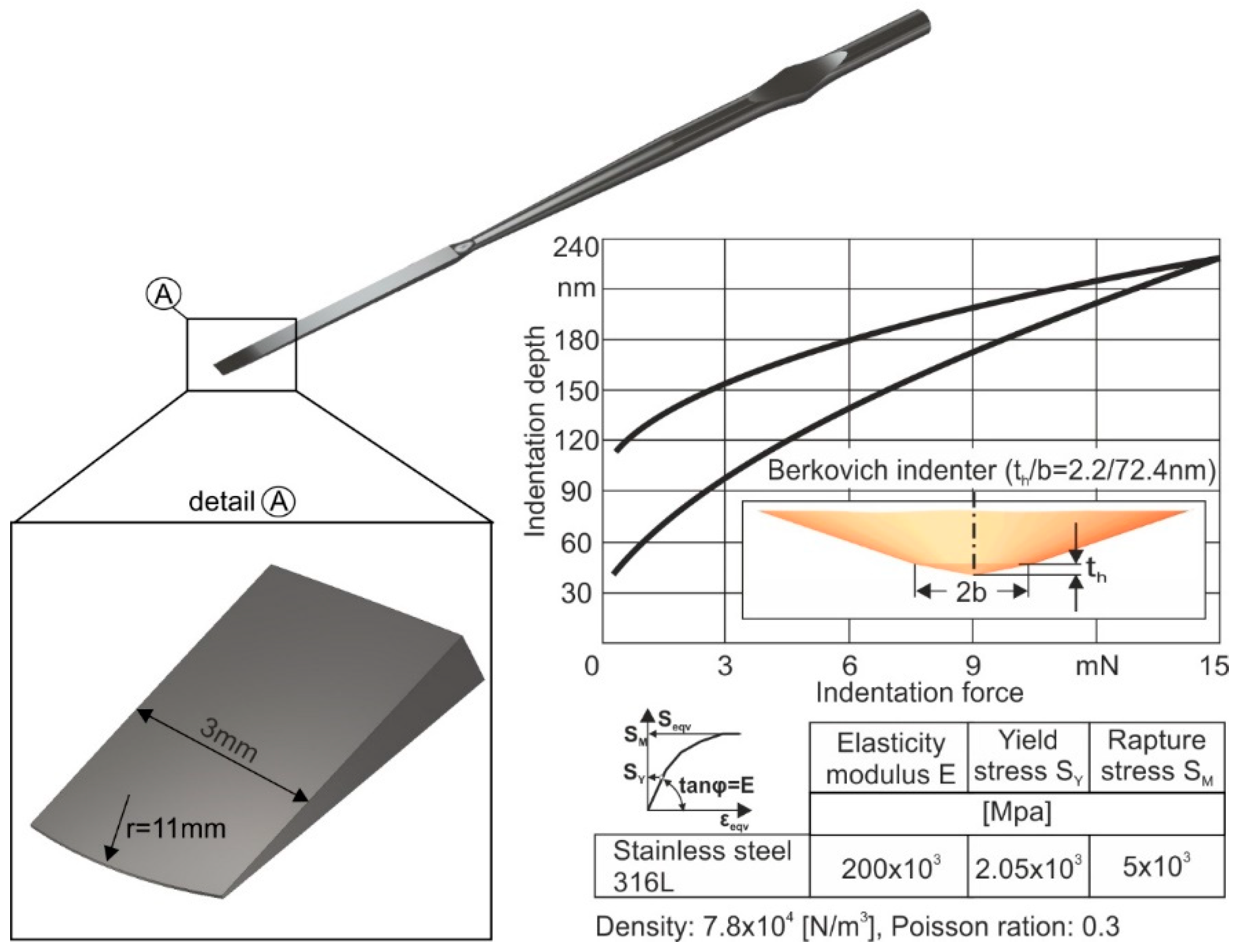
The instrument geometry and its mechanical properties were modeled next. A 3-mm straight osteotome, commonly used for rhinoplasty surgical procedures, was used as a case study in this work. The geometry of the straight osteotome along with its mechanical properties applied in the developed FEA-model, are shown in
Figure 5. As a reference material for the osteotome, a stainless steel 316L was considered. For determining its mechanical properties, nanoindentations were conducted using a FISCHERSCOPE H100 device, coupled with appropriate FEM-simulations [
16]. For excluding the specimen roughness effect on the results accuracy, 30 measurements per nanoindentation were carried out, thus stabilizing the moving average of the indentation depth versus the indentation force. The load-displacement diagram as well as the extracted mechanical characteristics are shown in the right part of
Figure 5.
For investigating the potential of the instrument material to withstand the repetitive dynamic loads as it penetrates the nasal bone, it is necessary to know its fatigue strength. The fatigue strength of 316L stainless steel was assessed via perpendicular impact tests and appropriate FEM simulations [
10,
11]. The impact tester device was designed and manufactured by the Laboratory for Machine Tools and Manufacturing Engineering of the Aristotle University of Thessaloniki in conjunction with the company Impact-BZ (see
Figure 6a) (London, UK) [
17]. A ceramic ball of 5 mm diameter penetrates repetitively into the specimen under an adjustable maximum load. With the aid of a proportional, integral and differential (PID) controller, the output voltage of a variable transformer, through a direct current (DC) motor is adjusted to attain constant impact force peaks throughout the entire test duration. Moreover, measurements of current, forces, temperatures, and further process parameters are conducted and monitored.
A characteristic imprint, scanned by white light via confocal microscopy, at a load of 15 N after 10
6 impacts is shown in
Figure 6b. The material removal starts at a remaining imprint depth of approximately equal to the double of the insert’s arithmetic roughness Ra. This happens for avoiding the interpretation of surface asperity’s damages as material damages. The critical impact force for fatigue damage initiation after 10
6 impacts for stainless steel 316L amounts to 15 N. A way to present fatigue data of the stainless steel 316L is offered by the Smith-like diagram, where both S
max and S
min are plotted as a function of the mean stress S
m. Smith diagram presents the maximum load alterations versus its mean value for a fatigue safe operation of a stressed material (see
Figure 6c). The Woehler diagram applied in the present study illustrates the fatigue safe maximum stress versus the number of repetitive loads alternating from zero up to a maximum value. The latter diagram is important in order to know the fatigue failure stress of stainless steel 316L after a certain accumulated number of impacts. The dependent critical fatigue stress upon the accumulated number of impacts of the osteotome was used as an input parameter in the developed FEA-model for describing its wear evolution during its impact with the nasal bone, as it will be further explained.
2.4. The Developed FEA-Model
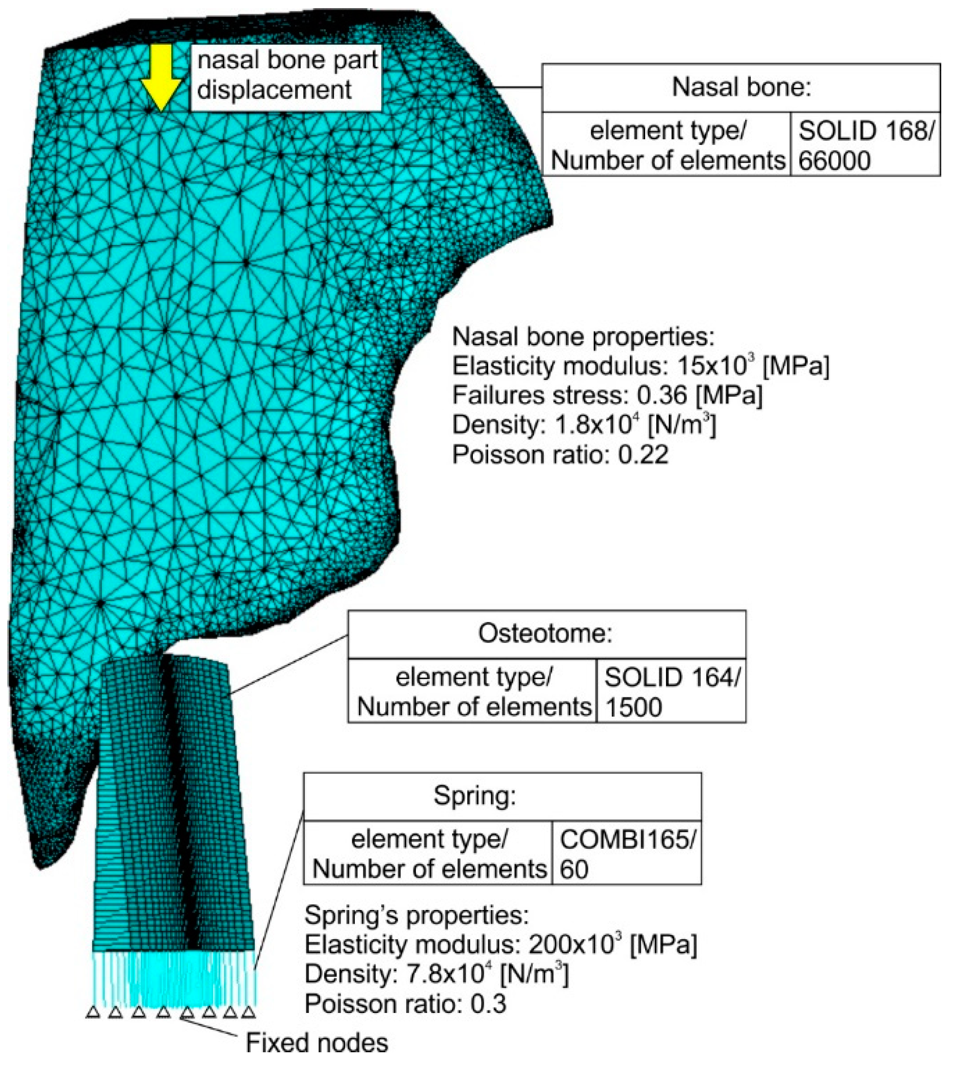
The developed FEA-model and the corresponding discretisations of all model parts are shown in
Figure 7. Convergence studies were conducted to determine the optimal mesh density and attain a mesh independent grid [
18]. Dependent upon the employed material, different solid elements were used. In the case of nasal bone due to its irregular shape, solid elements possessing a pyramid geometry were necessary to be used (solid 168) for generating the meshed volume. Moreover, rectangle solid elements (solid 164) were applied in the case of the instrument. In the osteotome center, where the impact takes place, the discretisation network is denser. Since both solid element types, which are the only available solid elements for an explicit dynamic analysis in ANSYS software, do not support the calculation of the developed forces during impact at different times, a different element type was used.
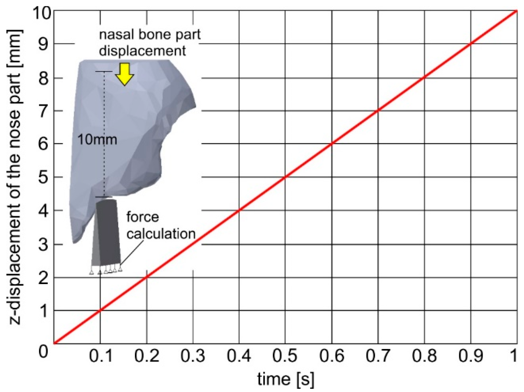
More specifically, linear elastic spring elements were generated (combi165) as a connection between the instrument elements and the fixed nodes in its bottom surface describing the boundary conditions. The spring stiffness was set equal to the osteotome’s elasticity modulus. By using the elastic spring elements, the developed impact loads at each time can be determined. Due to the usage of the spring elements in the instrument, a reverse parts’ motion was simulated by the developed FEA-model compared to the real one, leading to the osteotome and nasal bone fracture. In this way, it was assumed that instead of the osteotome, the nasal bone is moving against the instrument. The time course of the nasal bone displacement is linked to a certain curve as shown in
Figure 8. Every impact was considered to last 0.1 s. The following nonlinear equations [M]{ü}+ [K]{u}=[F], where [M] and [K] are the mass and stiffness matrix, governing the impact between the osteotome and the nasal bone, were solved using an iterative solution method. The equilibrium differential equations are integrated for incremental solution time steps of few milliseconds. Due to the employed explicit method, linear change in displacement over the time of each solution step between t
n and t
n+dt was considered. All solution steps were well-converged, indicating that all relevant equations have dropped below the default residual target of 10
−5 [
19,
20].
In the developed FEA-model, a surface-to-surface contact was applied for describing the interface between the nasal bone and the instrument. In addition, an eroding contact was applied between instrument and nasal bone material [
21,
22]. In this way, elements involved in the contact definition are subjected to erosion (element deletion) according to a material failure criterion and not directly due to the eroding contact restrictions. The contact surface is updated as external elements are deleted. More specifically, in the FEM-calculations performed, it was assumed that each solid element of the osteotome can withstand an applied load, which leads to stresses lower than its critical fatigue stress. If the developed element stress during impact exceeds the critical fatigue stress, then the element is deleted for simulating the crack and debris formation. In the osteotome case, the critical fatigue stress for osteotome element deletion is a variable parameter dependent upon the accumulated number of impacts. This parameter was approached by calculating its Woehler diagram via perpendicular impacts tests and appropriate FEM simulation (see
Figure 6) [
10]. Moreover, in the case of the nasal bone, the failure stress for element deletion was kept constant considering already published results [
23,
24,
25]. In the FEA-model developed, the instrument material was described with piecewise linear plasticity and strain rate independent law (see
Figure 5), whereas the nasal bone as an elastic material with failure. The density of the nasal bone was determined considering the results shown in the computed tomography (Hounsfield Unit (HU)) and a related diagram describing a correlation between HU and mass density of bone [
26,
27]. The density value was set to 1900 kg/m
3. Bone was assigned to cortical bone properties (Young modulus: 15 GPa and Poisson ratio: 0.22) [
23,
24,
25].
3. Analytical Results
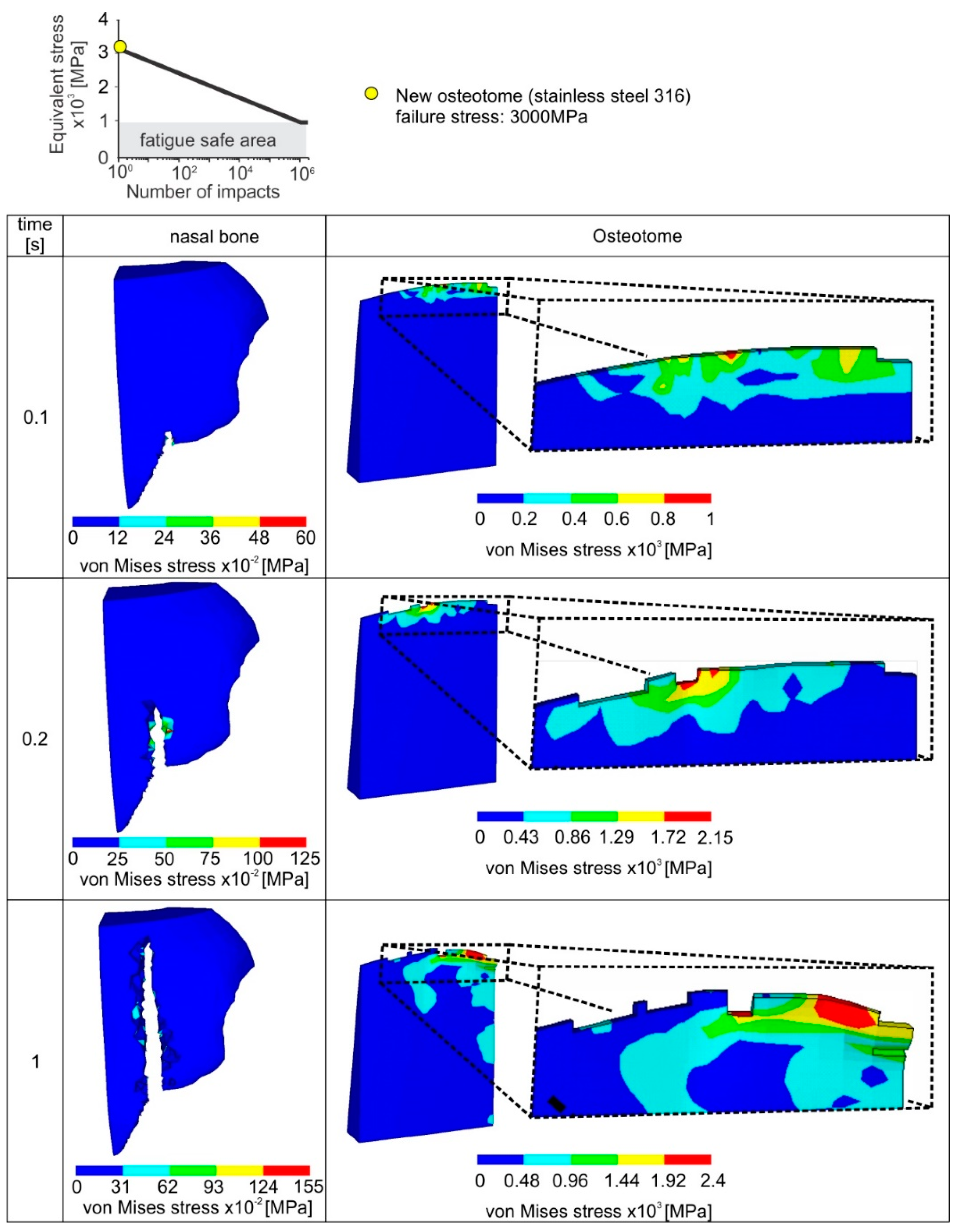
An analytical description of the progressive instrument and nasal bone failure during the first accumulated 10 impacts via the developed FEA-model is shown in
Figure 9. It was considered that each impact lasts 0.1 s. According to the diagram in
Figure 8, every impact is associated with nasal bone fracture of 1 mm. As the osteotome penetrates deeper into the nasal bone, the developed stresses are increased. If the developed maximum stress during the impact is larger than the element critical fatigue stress determined by the instrument Wohler diagram, the failure criterion is met and the related element is deleted.
The critical fatigue stress for fatigue damage initiation of a new instrument amounts to 3 GPa (see upper part of
Figure 9). Due to the increased fatigue properties of the new osteotome, only slight damages appear in the osteotome tip. In this way, after a cutting length of 10 mm (10 impacts), the wear of the osteotome amounts only to approximately 200 μm. The cutting ability of the osteotome remains unaffected, minimizing the risk of postoperative complications. In the same figure, the surface integrity of the fractured nasal bone is depicted. The latter is significantly affected by the osteotome tip geometry.
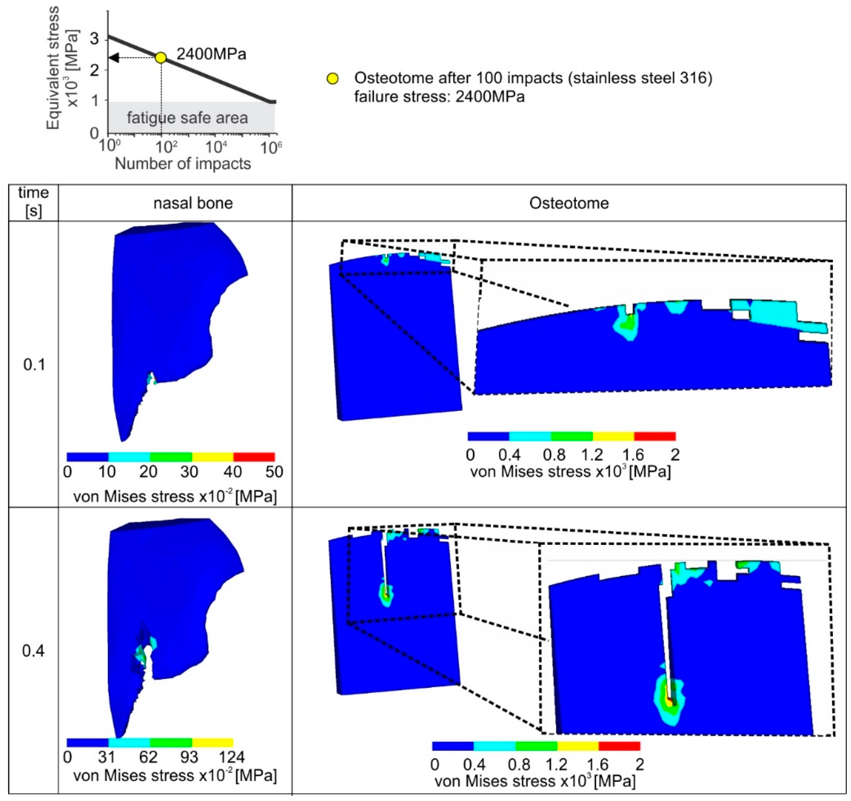
When an already used osteotome is employed after an accumulated number of 100 impacts, then a percentile decrease of 20% of the pristine critical fatigue stress for element deletion occurs according to the applied stainless steel’s Woehler diagram (see upper part of
Figure 10). According to the results shown in
Figure 10, a comparably larger amount of elements are overloaded in a case of an already used osteotome. It has to be pointed out that in each incremental solution step the contact between the osteotome and the nasal bone is updated after the elements’ deletion. As a consequence, the instrument wear propagates quickly, i.e., after 104 impacts and the developed wear width is over 2 mm. Moreover, owing to the damaged instrument tip after 104 impacts, the surface topography of the fractured nasal bone is characterized by many cracks and intense concavities. Since such a resulting surface of nasal bone, due the usage of a rapidly worn instrument, is associated with potential postoperative problems, the instant replacement of the worn instrument is required.
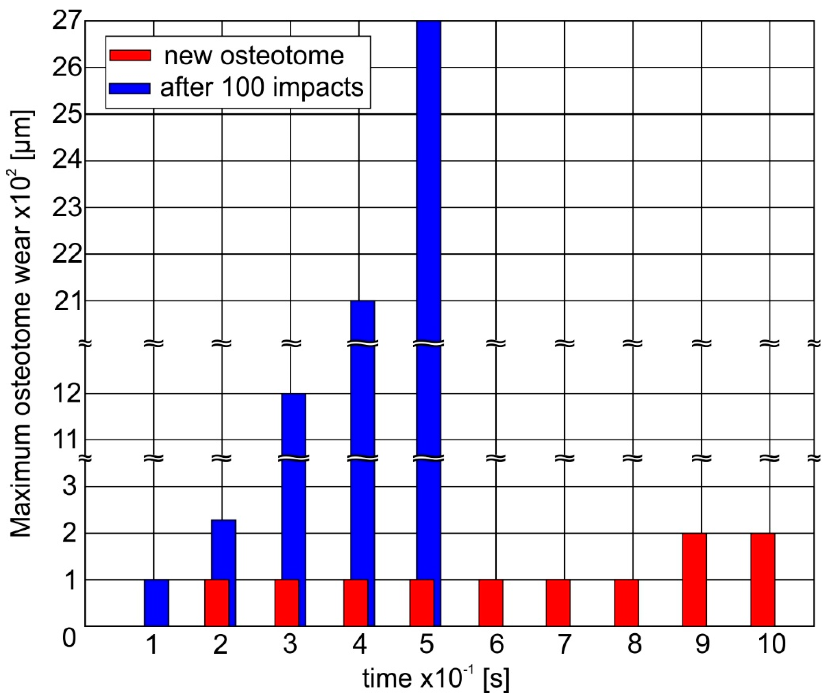
An overview concerning the ability of a new instrument to withstand the impact loads during its penetration into the nasal bone is shown in
Figure 11. It can be observed that the maximum wear at the instrument tip amounts only to 200 μm at the first 10 impacts due to the improved fatigue properties of a new stainless steel instrument. However, after an accumulated number of 100 impacts, the deteriorated fatigue strength of the osteotome results in a rapid wear evolution. Hereupon, a wear width larger than 2 mm develops and the osteotome can be considered as damaged.
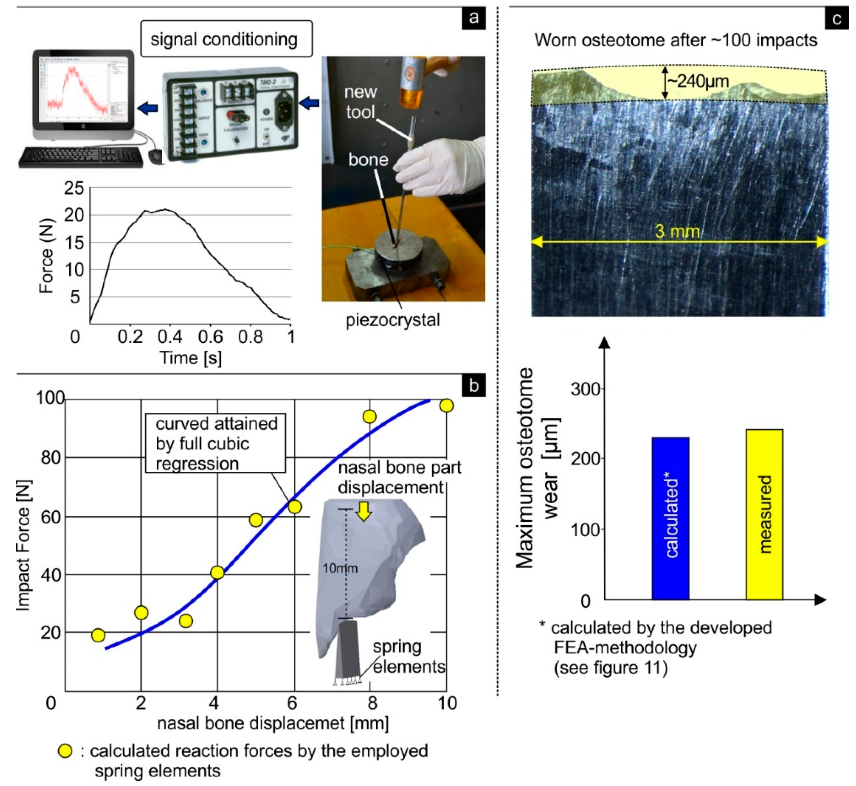
In order to validate the possibility of the FEA methodology developed to predict the osteotome wear status during the nasal bone surgical operation, the following procedure was conducted. In the first step, using a new osteotome manufactured from stainless steel, impacts were conducted on a rib bone of a chicken. The structure and the properties of the bone employed resembles the human nasal bone (which was considered as a cortical bone) [
28]. By integrating a piezocrystal in the base and with the aid of an analog to digital converter, the developed forces for attaining a crack of approximately 1 mm were measured and amounted to approximately 21 N (see
Figure 12a). Moreover, via the applied spring elements in the developed FEA-model, the time-dependent forces can be calculated as a function of the osteotome penetration into the nasal bone. The curve indicated in
Figure 12b was approximated by full cubic regression of the calculated points describing the developed loads at certain impact times. The developed reaction force amounts to approximately 20 N for attaining a penetration depth of 1 mm during the impact. This value is similar to the measured one, verifying the potential of the developed FEA-methodology to predict the osteotome wear status during surgery of the nasal bone.
Figure 12c illustrates a characteristic fracture of the cutting edge of a straight osteotome that was clinically used after ~100 impacts. The fracture pattern resembles that predicted by the FEA model (see
Figure 10). A comparison between the maximum measured wear and the predicted one by the developed FEA-model indicates similar values. Thus, the clinical data attained for the osteotome verify also the accuracy, trustworthiness and reliability of the proposed 3D FEM-based model for predicting the wear status of the osteotome during the nasal osteotomy.
4. Discussion
A lateral nasal osteotomy should be precise, reproducible and avoid irregular fragmentation of the nasal bone [
7,
13]. Although the surgeon’s experience and nasal bone anatomy are factors that need to be considered for obtaining the desired aesthetic outcome and for avoiding postoperative complications, the choice of proper surgical technique and accurate osteotome is considered a more crucial factor by many surgeons [
7,
8]. Many studies have compared the different techniques of nasal osteotomies in terms of edema and postoperative ecchymosis [
7,
29]. Other studies refer to predictability of fracture lines [
29,
30], prevention of the collapse of the nasal bones and prediction of the different fracture patterns of the nasal bone [
4,
5,
31].
However, to the best of our knowledge there are no studies in literature referring to the quality of the surgical instruments, e.g., the osteotome and specifically the cutting edge of the osteotome so as to achieve the desired cosmetic result of the lateral nasal osteotomy. For the first time, a FEA-based methodology is introduced to simulate the lateral nasal osteotomy. The proposed FE model can simulate the fracture patterns of both the nasal bone and osteotome and can offer a visual depiction of the von Mises stress distributions developed. This information can facilitate the proper selection of the osteotome used during the surgical procedure (in terms of geometry and size). Additionally, it can offer valuable information for re-designing osteotomes (e.g., finding critical values and geometries of cutting edge), in order to minimize the damage of nasal bone and consequently minimize post-operative edema.
The decision for replacement of an osteotome is usually taken by the individual surgeon, thus the individual surgeon’s judgment plays a key factor but it also raises certain risks. A worn (reused) osteotome requires more force to be used during the light “tap tap” of the mallet throughout the osteotomy procedure and can lead to extensive and abnormal fracture of the nasal bone (see
Figure 10). This complicates its precise handling by the surgeon and can make it difficult to follow the defined fracture patterns. Moreover the risk of provoking extra undesirable micro-fractures and irregularities in the nasal bone is high as denoted by the FEA-model (
Figure 10). An ideal osteotome allows for less force to be used during the osteotomy, and provides accurate, predictable and reproducible aesthetic and functional outcome [
1,
9]. Moreover, there is less risk of wounding the soft-tissue and causing postoperative complications.
Nowadays, the osteotome is presumed to be a disposable instrument by surgeons. Nevertheless, there is luck of certain protocols and well-defined “correct” frequency for replacing an osteotome. One significant key finding of this research is that the introduced FEA-based methodology can provide a general guideline and suggestions that can afford the rhinoplasty surgeon with important quantitative information, concerning the wear status of the osteotome, so as to maximize its usability and ensure that it will function correctly during critical surgical maneuvers.
The agreement of the FEM-calculated results with the experimental ones (measured by the force to penetrate the bone at a specific length (
Figure 12a,b)) verify that the proposed 3D FE-model is able to generate veritable and trustworthy results on the wear status of the osteotome during a lateral nasal osteotomy. The visual resemblance of the fracture patterns between a clinically used osteotome and those depicted by the FE-model serves as an additional verification of the accuracy of the FEA-based methodology introduced (
Figure 12c). Nevertheless, when considering the fracture pattern of the nasal bone it should be mentioned that the proposed FEA model depicts only the virtual situation. Therefore, supplementary clinical evaluations depicting the nasal bone fracture are needed to validate the fidelity of the FE prediction clinically in the case of the nasal bone.
In summary, the developed FEA-based methodology has potentially important implications for both rhinoplasty surgeons, in term of surgical planning and aesthetic outcome as well as for engineers in terms of instrument/osteotome design.
5. Conclusions
This paper presents a FEA-based methodology for the prediction of osteotome damage status during nasal bone surgical operations. The methodology developed offers a prediction of critical number of impacts which can be used for preventive replacement of the osteotome before its extensive fracture, thus maximizing the osteotome’s usability and ensuring that it will function efficiently and correctly during critical surgical maneuvers. Depiction of fracture patterns and developed von Mises stresses for the osteotome and the nasal bone were also obtained. This information has potentially important implications for rhinoplasty, instrument/osteotome design, surgical planning and aesthetic outcome.
Author Contributions
Conceptualization, G.S.; Investigation, G.S., F.S., A.B., D.S. and H.B.; Methodology, G.S., F.S. and A.B.; Software, G.S., F.S., and A.B.; Supervision, G.S.; Validation, F.S. and D.S.; Writing—original draft, G.S. and F.S.
Funding
This research did not receive any specific grant from funding agencies in the public, commercial, or not-for-profit sectors.
Conflicts of Interest
The authors have no conflict of interest to declare.
References
- Huang, H.; Luo, X.; Cheng, X.; Shi, B.; Li, J. Biomechanical simulation of correcting primary unilateral cleft lip nasal deformity. PLoS ONE 2018, 13, e0199964. [Google Scholar] [CrossRef] [PubMed]
- Huang, H.; Li, Y.; Luo, X.; Cheng, X.; Shi, B.; Li, J. Mechanical analyses of critical surgical maneuvers in the correction of cleft lip nasal deformity. PLoS ONE 2018, 13, e0195583. [Google Scholar] [CrossRef] [PubMed]
- Liong, K.; Lee, S.J.; Lee, H.P. Preliminary Deformational Studies on a Finite Element Model of the Nasal Septum Reveals Key Areas for Septal Realignment and Reconstruction. J. Med. Eng. 2013, 2013, 250274. [Google Scholar] [CrossRef] [PubMed]
- Manuel, C.T.; Harb, R.; Badran, A.; Ho, D.; Wong, B.J.F. Finite Element Model and Validation of Nasal Tip Deformation. Ann. Biomed. Eng. 2017, 45, 829–838. [Google Scholar] [CrossRef] [PubMed][Green Version]
- Tjoa, T.; Manuel, C.T.; Leary, R.P.; Harb, R.; Protsenko, D.E.; Wong, B.J.F. A Finite Element Model to Simulate Formation of the Inverted-V Deformity. JAMA Facial Plast. Surg. 2016, 18, 136–143. [Google Scholar] [CrossRef] [PubMed][Green Version]
- Shamouelian, D.; Leary, R.P.; Manuel, C.T.; Harb, R.; Protsenko, D.E.; Wong, B.J. Rethinking nasal tip support: A finite element analysis. Laryngoscope 2015, 125, 326–330. [Google Scholar] [CrossRef]
- Ghassemi, A.; Aosteyoub, A.; Modabber, A.; Bohluli, B.; Prescher, A. Lateral nasal osteotomy: A comparative study between the use of osteotome and a diamond surgical burr—A cadaver study. Head Face Med. 2013, 9, 41–47. [Google Scholar] [CrossRef]
- Bloom, J.D.; Ransom, E.R.; Antunes, M.B.; Becker, D.G. Quantifying the Sharpness of Osteotomes for Dorsal Hump Reduction. Arch. Facial Plast. Surg. 2011, 13, 103–108. [Google Scholar] [CrossRef][Green Version]
- Ransom, E.; Antunes, M.; Bloom, J.; Becker, D. Quantifying Osteotome Sharpness: Comparing the Major Manufacturers. Otolaryngol. Head Neck Surg. 2012, 146, 707–711. [Google Scholar] [CrossRef]
- Bouzakis, K.-D.; Michailidis, N.; Lontos, A.; Siganos, A.; Hadjiyiannis, S.; Giannopoulos, G.; Maliaris, G.; Erkens, G. Characterization of cohesion, adhesion and creep-properties of dynamically loaded coatings through the impact tester. Z. Met. 2001, 92, 1180–1185. [Google Scholar]
- Bouzakis, K.-D.; Charalampous, P.; Skordaris, G.; Dimofte, F.; Ene, N.M.; Ehinger, R.; Gardner, S.; Modrzejewski, B.S.; Fetty, J.R. Fatigue and adhesion characterization of DLC coatings on steel substrates by perpendicular and inclined impact tests. Surf. Coat. Technol. 2015, 275, 207–213. [Google Scholar] [CrossRef]
- Behrbohm, H. Ästhetisch-funktionelle Rhinoplastik: Laterale Osteotomien-ein Update. Ästhet. Fachbeitrag Face 2014, 3, 26–30. [Google Scholar]
- Behrbohm, H.; Kaschke, O.; Nawka, T.; Swift, A. Ear, Nose, and Throat Diseases with Head and Neck Surgery, 3rd ed.; Thieme Medical Publisher: Stuttgart, Germany, 2014. [Google Scholar]
- Michailidis, N.; Stergioudi, F.; Omar, H.; Tsipas, D.N. FEM modeling of the response of porous Al in compression. Comput. Mater. Sci. 2010, 48, 282–286. [Google Scholar] [CrossRef]
- Michailidis, N.; Stergioudi, F.; Omar, H.; Tsipas, D.N. An image-based reconstruction of the 3D geometry of an Al open-cell foam and FEM modeling of the material response. Mech. Mater. 2010, 42, 142–147. [Google Scholar] [CrossRef]
- Bouzakis, K.-D.; Michailidis, N.; Hadjiyiannis, S.; Skordaris, G.; Erkens, G. The effect of specimen roughness and indenter tip geometry on the determination accuracy of thin hard coatings stress-strain laws by nanoindentation. Mater. Charact. 2002, 49, 149–156. [Google Scholar] [CrossRef]
- Available online: www.impact-bz.com (accessed on 11 December 2019).
- Skordaris, G. Fatigue Strength of Diamond Coating-Substrate Interface Quantified by a Dynamic Simulation of the Inclined Impact Test. J. Mater. Eng. Perform. 2014, 23, 3497–3504. [Google Scholar] [CrossRef]
- ANSYS, Inc. Release 18 documentation.
- Harewood, F.J.; McHugh, P.E. Comparison of the implicit and explicit finite element methods using crystal plasticity. Comput. Mater. Sci. 2007, 39, 481–494. [Google Scholar] [CrossRef]
- Skordaris, G.; Bouzakis, K.-D.; Charalampous, P. A dynamic FEM simulation of the nano-impact test on mono- or multi-layered PVD coatings considering their graded strength properties determined by experimental-analytical procedures. Surf. Coat. Technol. 2015, 265, 53–61. [Google Scholar] [CrossRef]
- Bouzakis, K.-D.; Makrimallakis, S.; Katirtzoglou, G.; Bouzakis, E.; Skordaris, G.; Maliaris, G.; Gerardis, S. Coated tools’ wear description in down and up milling based on the cutting edge entry impact duration. CIRP J. Manuf. Sci. Technol. 2012, 61, 115–118. [Google Scholar] [CrossRef]
- Coto, N.P.; Meira, J.B.C.; Dias, R.B.; Driemeier, L.; de Oliveira Roveri, G.; Noritomi, P.Y. Assessment of nose protector for sport activities: Finite element analysis. Dent. Traumatol. 2012, 28, 108–113. [Google Scholar] [CrossRef]
- Leary, R.P.; Manuel, C.T.; Shamouelian, D.; Protsenko, D.E.; Wong, B.J.F. Finite Element Model Analysis of Cephalic Trim on Nasal Tip Stability. JAMA Facial Plast. Surg. 2015, 17, 413–420. [Google Scholar] [CrossRef] [PubMed]
- Mirzaali, M.J.; Schwiedrzik, J.J.; Thaiwichai, S.; Best, J.P.; Michler, J.; Zysset, P.K.; Wolframac, U. Mechanical properties of cortical bone and their relationships with age, gender, composition and microindentation properties in the elderly. Bone 2016, 93, 196–211. [Google Scholar] [CrossRef]
- Garcia, S.; Schmidt, J.; Ploeg, H. A validation study: Using CT scans to calculate volume, weight and density. In Proceedings of the ISB XXth Congress—ASB 29th Annual Meeting, Cleveland, OH, USA, 31 July–5 August 2005; p. 850. [Google Scholar]
- Schreiber, J.J.; Anderson, P.A.; Hsu, W.K. Use of computed tomography for assessing bone mineral density. Neurosurg. Focus 2014, 37, 1–8. [Google Scholar] [CrossRef] [PubMed]
- Aerssens, J.; Boonen, S.; Lowet, G.; Dequeker, J. Interspecies Differences in Bone Composition, Density, and Quality: Potential Implications for in Vivo Bone Research. Endocrinology 1998, 139, 663–670. [Google Scholar] [CrossRef] [PubMed]
- Gabra, N.; Rahal, A.; Ahmarani, C. Nasal Osteotomies, A Cadaveric Study of Fracture Lines. JAMA Facial Plast. Surg. 2014, 16, 268–271. [Google Scholar] [CrossRef] [PubMed]
- Sabet, F.A.; Najafi, A.R.; Hamed, E.; Jasiuk, I. Modelling of bone fracture and strength at different length scales: A review. Interface Focus 2016, 6, 20150055. [Google Scholar] [CrossRef]
- Siswanto, W.A.; Hua, C.S. Strength Analysis of Human Skull on High Speed Impact. Int. Rev. Mech. Eng. 2012, 6, 1508–1514. [Google Scholar]
© 2019 by the authors. Licensee MDPI, Basel, Switzerland. This article is an open access article distributed under the terms and conditions of the Creative Commons Attribution (CC BY) license (http://creativecommons.org/licenses/by/4.0/).


