Article

Passive Vibration Reduction Analysis of the Mistuned Blisk Deposited Hard Coating Using Modified Reduced-Order Model

Automation School of Binjiang College, Nanjing University of Information Science and Technology, Wuxi 214105, China
*
Authors to whom correspondence should be addressed.
Coatings 2019, 9(12), 812; https://doi.org/10.3390/coatings9120812
Submission received: 11 September 2019 / Revised: 6 November 2019 / Accepted: 7 November 2019 / Published: 2 December 2019
(This article belongs to the Section Thin Films)

Abstract

:
To improve the reliability and safety of the mistuned blisk (integrally bladed disk), a novel strategy for passive vibration reduction by the hard coating was developed, and the vibration and damping characteristics of the HCM (hard-coating mistuned) blisk were investigated in this work. Firstly, by the proposed criterion called FDSD (frequency difference and its standard deviation), a classical reduced-order model established by the component mode synthesis method was modified to carry out modal analysis for high computational efficiency. Then, forced vibration responses of the HCM blisk were achieved by the Rayleigh damping model. Next, a specific benchmark of a mistuned blisk deposited NiCoCrAlY + YSZ hard coating was chosen to conduct numerical calculations, and the results were compared with those obtained from the FOM (full-order model) and experimental test, respectively. Finally, the influence of the hard coating and coating thickness on the mistuned blisk were investigated, in particular.

1. Introduction

The integrally bladed disk (known as the blisk) was first applied to the power turbines of Bristol Siddeley Nimbus engines [1], and it has obtained increasingly widespread use in the design of modern aero-engines. Instead of the traditional assemblies of a disk, some individual, removable blades and dovetail attachments at joints, the blisk was manufactured as the single structure either by welding blades on rotors or by machining entire bladed disks from single pieces of metal. As a result, it features the lesser number of parts, apparent weight saving and reduced aero-dynamic losses, in turn, the practical problems of crack initiation and subsequent propagation on the contact area of the traditional bladed disk assemblies were eliminated effectively [2].
In tuned conditions, the blisk was a rotationally periodic structure with identical blades, and one piece of sector of the blisk was sufficient to conduct the vibration analysis by using cyclic symmetry properties [3,4]. However, some random deviations among the blades occur inevitably due to manufacture errors, wear during engine service and other causes. These blade-to-blade discrepancies, referred to as mistuning, have a drastically larger effect on the forced response than the ideal, tuned design [5]. Generally, the attendant increase of vibration stresses can bring about premature high cycle fatigue (HCF) of the blades, which was a costly and risky issue for aero-engines. It was estimated by the U.S. Air Force that about 55% of fighter jet engine safety Class A mishaps and 30% of all jet engine maintenance costs were due to HCF [6]. Thus, it was very necessary to predict and reduce the maximum blade response as a result of mistuning, and improve the performance and reliability of aero-engines.
It was well known that the vibration damping plays a significant role in the vibration reduction of structures. Due to the absence of the internal vibration damping provided by joints, the blisk was more vulnerable to the high-level vibration than the bladed disk assemblies, even severe resonance when aero-engine works in high gas temperature and pressure environments. Therefore, additional damping treatment was essential to conduct vibration reduction of the mistuned blisk. So far, various dry friction dampers have been used in the bladed disk assemblies because of their simplicity in implementation and superiority in performance, such as the shroud friction dampers [7,8], the under-platform dampers [9,10] and the friction ring dampers [11,12]. However, these traditional dampers were very difficult to apply to the blisk due to its special one-piece structure. Moreover, the vibration reduction technology with viscoelastic damping materials was no longer working well, because it cannot bear the high temperature and its damping capabilities were impacted by the temperature obviously [13]. Therefore, an improved vibration reduction technology with new dampers was very urgent to be developed for the mistuned blisk.
Hard coating was a kind of coating materials prepared by the metal substrate, the ceramic substrate and their mixtures, and it was mainly used as the surface treatment which makes the composite structures have special and superior performance, such as the anti-friction coating (or anti-wear coating) [14,15], the thermal barrier coating [16,17,18] and the anti-corrosive coating [19,20,21], etc. In recent years, the significant mechanical damping capacities of hard coating generated by the friction energy dissipation of internal particles of coating materials [22] have been found by a number of researchers. Subsequently, hard coating was used widely as the vibration dampers to reduce the resonant stress of vibrating structures for its nicer stability and high damping capacities in high temperature [23], such as the titanium plates [24,25,26,27], the cantilever beams [28,29], the cylindrical thin shells [30,31,32] and the individual blades [33,34,35], etc. Moreover, another great advantage of hard coating was that the resonant peaks of the forced response of vibrating structures can be suppressed remarkably without influencing the structural mass and stiffness significantly because of its thin thickness.
In order to apply this vibration reduction technology, the dynamic model and the prediction of vibration characteristics of the HCM blisk need to be investigated, such as the spring-mass models (or lumped parameter models) [36,37,38,39], the beam-plate models (or continuous parameter model) [40,41], and the FEMs (finite element models) [42,43]. In spring-mass models, each sector of the blisk was usually modeled using just one or a few lumped masses connected by springs, and the qualitative results were useful for gaining a rough understanding of the influence of the mistuning on the vibration characterizes of the blisk, most notably the identification of critical blades and the increase in forced response levels which can be caused by mistuning. However, such simple models have limitations when quantitative predictions were of interest for practical applications. The beam-plate models were able to reflect vibration characteristics for a wider class of the mistuned blisk although they still have a restricted range of applicability. In industrial applications, the realistic FEMs featuring high computational accuracy were widely used to avoid the various simplifying assumptions during the modeling process and to seek accurate answers to questions related to the mistuning. However, it was very difficult to investigate vibration characteristics of the mistuned blisk directly by using the realistic FEMs because of the drastically increased number of the DOFs (degrees of freedom).
Several modal reduction methods for the FEM of the mistuned blisk were proposed to reduce the amount of calculation without influencing the computational accuracy significantly. The first-generation ROMs (reduced-order models) were presented on the basis of the CMSM (component mode synthesis method), including the fixed-interface CMSM [44,45,46], the free-interface CMSM [47,48,49], and the hybrid-interface CMSM [50,51]. By using of a developed CMS-based ROM to conduct Monte Carlo simulations, a method to reduce the energy localization in mistuned bladed disks by application-specific blade pattern arrangement was studied efficiently by Hohl and Wallaschek [52]. On the basis of the relationship between tuned and mistuned blisk, a new ROM called SNM (subsets of nominal modes) was developed by Yang and Griffin [53,54], and then used by Beirow et al. [55] to analyze optimization-aided forced response analysis of a mistuned compressor bladed disks. Similarly, based on exact calculation of the response of a mistuned system using response levels for the tuned assembly together with a modification matrix constructed from the frequency response function (FRF) matrix of the tuned system and a matrix describing the mistuning, a new method for the dynamic analysis of mistuned bladed disks was presented by Petrov [56]. Subsequently, a simplified SNM called FMM (fundamental mistuning model) was developed by Feiner and Griffin [57], and then used by Chan and Ewins [58] and Kaneko et al. [59] to study natural characteristics and forced vibration response of the mistuned bladed disks, respectively. In addition, the RM (receptance method) and the CMM (component mode mistuning) method were proposed by Yang and Griffin [60] and Lim et al. [61] to study vibration characteristics of the mistuned bladed disks, respectively. Moreover, on the basis of a reduced-order meshless energy model, vibration characteristics of a 3D annulus of shroudless, mistuned blades attached to a flexible disk were investigated by McGee et al. [62] and Fang et al. [63], respectively.
This work highlights the vibration reduction analysis of the mistuned blisk by the hard coating. In Section 2, the theoretical investigation of forced response of the HCM blisk was conducted. Using the CMSM and the proposed criterion called FDSD, the modified ROM of the HCM blisk was developed to improve the computational efficiency without influencing the accuracy of calculation significantly, and then modal loss factors-the key characteristic representing the damping capacities-were achieved based on the modal strain energy method, next, the forced responses can be achieved using the Rayleigh damping model to obtain damping matrix. In Section 3, a mistuned blisk with depositing NiCoCrAlY + YSZ hard coating on both sides of the blades was taken as the benchmark to conduct vibration analysis, and the obtained results were compared with those from the FOM and experimental investigation with respect to the amount of calculation and the computation accuracy, respectively. Moreover, the influence of the hard coating and coating thickness on the mistuned blisk were investigated in terms of natural frequencies, modal loss factors and forced response.

2. Theoretical Investigation of the HCM Blisk

The solid model of the mistuned blisk considered here was shown in Figure 1. The disk and the blades were assumed as the tuned and mistuned components, respectively; in this work, the blades mistuning were simulated as the blade stiffness deviation or elastic modulus deviation to its nominal value, in fact, it was natural frequency deviation. By the atmospheric plasma spraying (APS) technology, the hard coating marked by blue color was deposited on both sides of all the blades. It should be noted that the HCM blisk was the large and complicated structure, therefore the reliable and modified ROM of the HCM blisk should be developed firstly to improve computational efficiency. The solution procedure for solving forced responses of the HCM blisk by the modified ROM was shown in Figure 2.

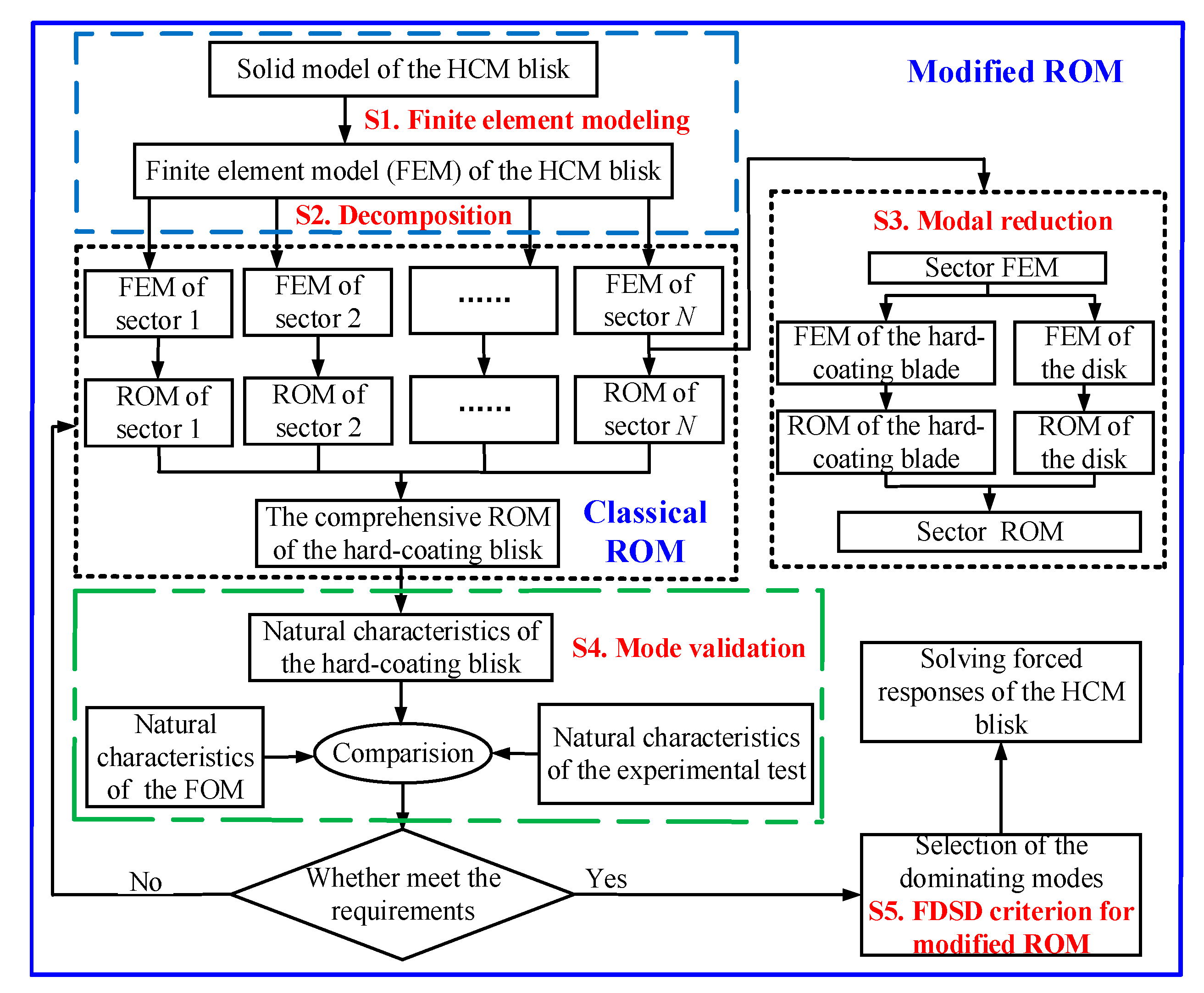
2.1. The Classical ROM of the HCM Blisk

The HCM blisk can be divided into the hard-coating blades (the blades deposited hard coating) and the disk.
The stiffness matrix, mass matrix and displacement vector of the hard-coating blades and disk can be expressed as K b , K ˜ d , M b , M ˜ d , x b and x ¯ d , respectively:
K b = [ K BB b K B Γ b K Γ B b K Γ Γ b ] ,   M b = [ M BB b M B Γ b M Γ B b M Γ Γ b ] ,   x b = { x B b x Γ b }
K ˜ d = [ K ˜ DD d h K ˜ D Γ d h K ˜ Γ D d h K ˜ Γ Γ d h ] ,   M ˜ d = [ M DD d h M D Γ d h M Γ D d h M Γ Γ d h ] ,   x ¯ d = { x ¯ D d x ¯ Γ d }
where, superscripts b and d refer to the hard-coating blades and the disk, respectively; superscript h represents the harmonic order, h 0 and h N / 2 , and N was the number of sectors of the HCM blisk; subscripts B and D represent the internal DOFs of the hard-coating blades and the disk, respectively; and subscript Γ indicates the interface DOFs between the hard-coating blades and the disk.
Based on the configurations and boundary conditions, the component ROM of the hard-coating blades can be developed by using the fixed-interface CMSM. And the equation of motion can be written as
[ M BB b M B Γ b M Γ B b M Γ Γ b ] { x ¨ B b x ¨ Γ b } + [ K BB b K B Γ b K Γ B b K Γ Γ b ] { x B b x Γ b } = { 0 f Γ b }
where, f Γ b represents the interface force between the hard-coating blades and disk. And then, the characteristic equation of the hard-coating blades can be obtained as
( K BB b λ b M BB b ) φ b = 0
where, λ b and φ b refer to the eigenvalues and mode shapes of the hard-coating blades, respectively.
Next, the main mode matrix of the hard-coating blades can be achieved by modal truncation as
Φ b = [ φ b , 1 φ b , 2 φ b , n ]
where, n represents the modal order of the truncated mode of the hard-coating blades.
Moreover, the constraint mode matrix of the hard-coating blades Ψ b were computed by the static problem as
[ K BB b K B Γ b K Γ B b K Γ Γ b ] { Ψ b I } = { 0 R Γ }
where, R Γ contains reaction forces due to the imposed unit displacements, I .
Solving the first block of Equation (6) yields
Ψ b = K BB b 1 K B Γ b
It should be noted that the columns of Ψ b were the solution vectors x of K BB b x = K B Γ b , therefore, the inverse matrix K BB b 1 in Equation (7) need not be computed.
Further, the physical displacement x b of the hard-coating blades was described as
x b = { x B b x Γ b } = [ Φ b Ψ b 0 I ] { p b b p Γ b } = U cb b p b
where, p b represents the modal coordinates of the hard-coating blades, U cb b refers to the modal conversion matrix of the hard-coating blades between the physical and modal coordinates, and I denotes an identity matrix.
Finally, in the absence of the structural coupling between the blades, the reduced mass and stiffness matrices of the hard-coating blades can be derived respectively as
M ¯ cb b = U cb b T M b U cb b = [ I I M b Γ b I M Γ b b I M Γ Γ b ]
K ¯ cb b = U cb b T K b U cb b = [ I Λ b 0 0 I K Γ Γ b ]
{ M b Γ b = M Γ b b T = Φ b T ( M BB b Ψ b + M B Γ b ) M Γ Γ b = Ψ b T ( M BB b Ψ b + M B Γ b ) + M Γ B b Ψ b + M Γ Γ b K Γ Γ b = K Γ Γ b + K Γ B b Ψ b
Based on the free-interface CMSM and the circumferential symmetrical theory, the main mode matrix Φ ˜ d h and constraint mode matrix Ψ ˜ d h of the disk can be obtained respectively as
Φ ˜ d h = [ Φ ˜ d , 1 h Φ ˜ d , 2 h Φ ˜ d , n h ]
Ψ ˜ d h = ( K DD d h ) 1 K D Γ d h
And then, the physical displacement x ¯ d of the disk can be described as
{ x ¯ d = { x ¯ D d x ¯ Γ d } = U cb d { p ˜ d d p ˜ Γ d } = U cb d p ˜ d U cb d = [ ( F I )   B ˜ diag ( Φ ˜ d h ) h = 0 , 1 , H ( F I )   B ˜ diag ( Ψ ˜ d h ) h = 0 , 1 , H 0 F I ]
where, B ˜ diag refers to the pseudo-block diagonal matrix, p ˜ d represents the modal coordinates of the disk, and F denotes the real-valued Fourier matrix [33].
Next, the reduced mass matrix M ˜ cb d and stiffness matrix K ˜ cb d of the disk can be obtained respectively as
M ˜ cb d = [ I M ˜ d Γ d M ˜ Γ d d M ˜ Γ Γ d ]
K ˜ cb d = [ Λ ˜ d 0 0 K ˜ Γ Γ d ]
{ M ˜ d Γ d = M ˜ Γ d d T = B ˜ diag h = 0 , 1 , H [ Φ ˜ d h T ( M ˜ DD d h Ψ ˜ d h + M ˜ D Γ d h ) ] M ˜ Γ Γ d = B ˜ diag h = 0 , 1 , H [ Ψ ˜ d h ( M ˜ DD d h Ψ ˜ d h + M ˜ D Γ d h ) + M ˜ Γ D d h Ψ ˜ d h + M ˜ Γ Γ d h ] K ˜ Γ Γ b = B ˜ diag h = 0 , 1 , H [ K ˜ Γ Γ b h + K ˜ Γ D b h Ψ ˜ d h ]
It should be noted, that the coupling effect between the harmonics in Equation (17) was inexistent because of the orthogonality of the circumferential modes.
Generally, the computational accuracy of the comprehensive ROM was affected by the coordinating conditions. Here, the comprehensive coordinating conditions of the interface displacement and force were used together as
{ x Γ b = x ¯ Γ d f Γ b = f Γ d
Substituting Equations (8) and (14) into Equation (18), the coupling constraint of the components can be obtained as
{ p ˜ d d p ˜ Γ d p b b p Γ b } = [ I 0 0 0 I 0 0 0 I 0 F I 0 ] { p ˜ d p ˜ Γ p b } = T cb p cb
Finally, the reduced mass matrix M cb and stiffness matrix K cb of the HCM blisk can be obtained as
M cb = [ I M ˜ d Γ d 0 M ˜ Γ d d M ˜ Γ Γ d + I M Γ Γ b ( F I ) T ( I M Γ b b T ) 0 ( I M b Γ b ) ( F I ) I ]
K cb = [ Λ ˜ d 0 0 0 K ˜ Γ Γ d + I K Γ Γ b 0 0 0 I Λ b ]
Generally, the blades were more vulnerable than the disk when aero-engines works in harsh conditions. Therefore, the disk and the blades were regarded as the tuned and mistuned component in this work, and the blade mistuning can be simulated by the offsets in modal stiffness Λ (or natural frequency ω ). The mistuned modal stiffness of the r -th mode for the n -th blade Λ ¯ b , n r can be expressed as follows
{ Λ ¯ b , n r = Λ b r + Δ Λ b r = Λ b r + δ n r Λ b r δ n r = ( ω ¯ n r / ω r ) 2 1
where, Λ b r and Δ Λ b r represent the modal stiffness of the hard-coating tuned blisk and the perturbation modal stiffness generated by the mistuning, respectively; δ n r denotes the mistuning coefficients of the n -th blade; ω r and ω ¯ n r denote the natural frequency of the hard-coating tuned and mistuned blisk, respectively.
Finally, the mistuned modal stiffness of the HCM blisk (or Equation (21)) can be rewritten as
K cb = [ Λ ˜ d 0 0 0 K ˜ Γ Γ d + I K Γ Γ b 0 0 0 Bdiag ( diag ( ( ω ¯ n r / ω r ) 2 Λ b r ) ) ]
Without considering the damping, the characteristic equation of the HCM blisk can be achieved as
( K cb λ r M cb ) ψ = 0
where, λ r and ψ r denote the eigenvalue and mode shapes of r -th mode of the HCM blisk.
And then, natural frequencies and mode shapes of the HCM blisk can be respectively achieved as:
λ = [ ω 1 2 ω 2 2 ω r 2 ]
ψ = [ φ 1 φ 2 φ r ]
Moreover, the emphasis of this work was the passive vibration reduction of the mistuned blisk using the damping capacities of hard coating. Therefore, the modal loss factors of the HCM blisk were very meaningful and significant to be evaluated here. To approximate the damping capacities of composite structures well, the energy-based method has been usually used by some researchers, such as Zheng et.al [64] and Curà et.al [65]. By using the MSEM (modal strain energy method), the modal loss factors of the HCM blisk can be given by
η r = ( η c MSE c , r + η b MSE b , r ) / ( MSE c , r + MSE b , r )
where, η b and η c represent the material loss factor of the mistuned blisk and the hard coating, respectively; MSE b , r and MSE c , r refer to the modal strain energy of the mistuned blisk and the hard coating, respectively.
Due to the nicer stability and reliability of the hard coating, the HCM blisk can be approximated as the linear damping system. Thus, the Rayleigh damping model, which has been widely used to capture the damping behavior of the vibrating structures [66], was applied to the HCM blisk due to its simplicity in implementation [67] and de-coupling of the governing equations [68]. Considering Equation (20), that was given by
{ α + β ω r 2 = η r ω r D cb = α M cb + β K cb
where, α and β were the unknown coefficient related to the mass matrix and the stiffness matrix respectively and D cb denotes the undermined damping matrix of the HCM blisk.
Finally, the equation of motion of the HCM blisk considering the damping can be achieved as
( K cb + i D cb ω r 2 M cb ) X cb = F cb
where, ω r represents the undermined natural frequency, X cb and F cb refer to the forced response and the excitation force of the HCM blisk, respectively.

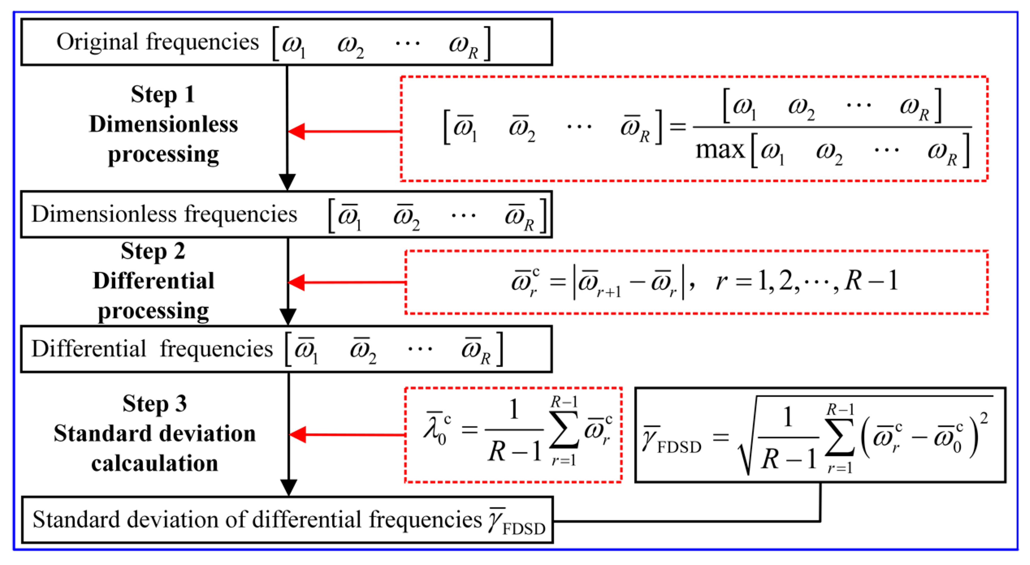
2.2. The Modified ROM of the HCM Blisk

The number of DOFs of the classical ROM was still large actually due to its composites. Therefore, the modified ROM with higher efficiency needs to be developed for forced vibration analysis. The dimension (or the amount of calculation) of the classical ROM, R , was determined by the dimension of main modes of the hard-coating blades U and main modes of the disk V and the dimension of constraint modes W , that can be described as
R = U + V + W
Considering Equation (30), Equations (25) and (26) can be rewritten respectively as
λ = [ ω 1 2 ω U 2 ω U + V 2 ω R 2 ]
ψ = [ φ 1 φ U φ U + V φ R ]
According to the theory of the modal superposition method, the forced response of the HCM blisk X cb can be expressed with a linearly independent mode shapes, that was described as
X cb = q 1 φ 1 + + q U φ U + q U + V φ U + V + q R φ R = r = 1 R q r φ r
where, q r denotes the r -th coefficient corresponding to mode shapes.
The forced response of vibrating structures was dominated by the low-order modes including the closely spaced modes, which can be obtained based on the proposed criterion called FDSD (frequency difference and its standard deviation). The fundamental solution procedure for solving FDSD was plotted in Figure 3, which can be explained as follows: firstly, the maximum value in eigenvalue (original frequencies) vector was searched, then the dimensionless processing of eigenvalue vector was carried out based on the obtained maximum eigenvalue, which was defined as the dimensionless eigenvalue vector; secondly, according to the mathematical difference concept; the difference between two adjacent eigenvalues was solved, the differential eigenvalue vector was then obtained; thirdly, the mean value of differential eigenvalue vector was solved, then the standard deviation of differential eigenvalue vector was obtained, which was defined as the γ ¯ FDSD . It should be noted, that the smaller the FDSD is, the closely spaced the modes will. Especially, the modes are treated as the same when the γ ¯ FDSD equals to zero.
Next, without considering the high-order modes, Equation (33) can be rewritten as
X cb = q 1 φ 1 + q 2 φ 2 + q Y φ Y = r = 1 Y q r φ r , Y R
where, Y represents the modal number of truncated high-order modes of the HCM blisk.
Finally, considering Equation (24), Equation (28) and Equation (34), the forced response of the HCM blisk X cb can be achieved:
X cb = r = 1 R φ ¯ r T F cb φ ¯ r ω r 2 ω 2 + i ω r D r
where, φ ¯ r and ω represents the r -th order regularized mode vectors and the excitation frequency.

3. Benchmark

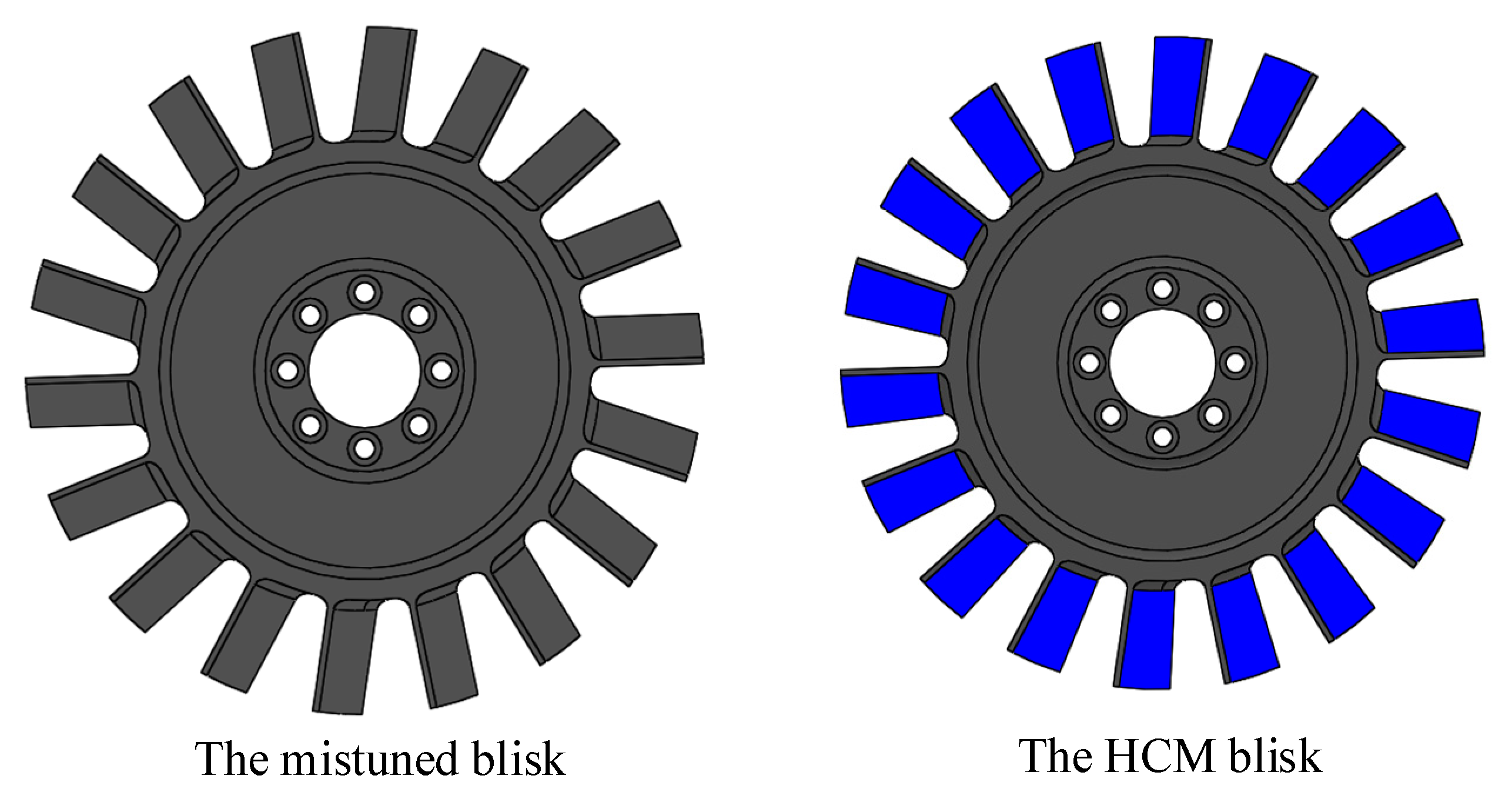
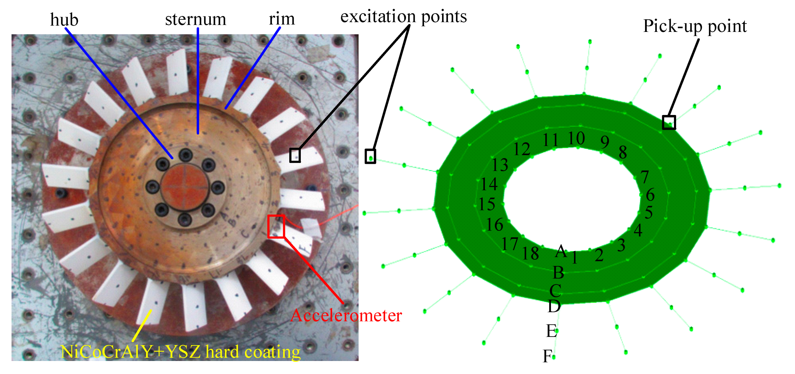
3.1. Research Systems

In this work, the blisk structure made of the carbon structural steel was manufactured as one-piece structure by the wire-electrode cutting technique. The blades were simplified as straight beams with uniform geometries, and the boundary conditions between the blade and disk are rigid. The mixture hard coating named NiCoCrAlY + YSZ was chosen and deposited on both sides of all the blades, whose single-layer coating thickness was defined as 0.1mm here. Moreover, some professional devices used in vibration experiments were listed: the PCB® modal hammer, the LMS SCDAC® mobile front-end, the B&K®-4517 lightweight accelerometer (Spectris, Surrey, the United Kingdom of Great Britain and Northern Ireland) and LMS Test. lab® mobile workstation. For understanding this study well, the fundamental process of vibration experiments for the mistuned blisk and HCM blisk was summarized and shown in Figure 4.
The geometrical and mechanical parameters associated with the mistuned blisk and hard coating were given in Table 1 and Table 2, respectively. Where, the Young’s modulus and loss factor of hard coating were obtained by the identification investigation by an inverse method at room temperature [30], respectively.

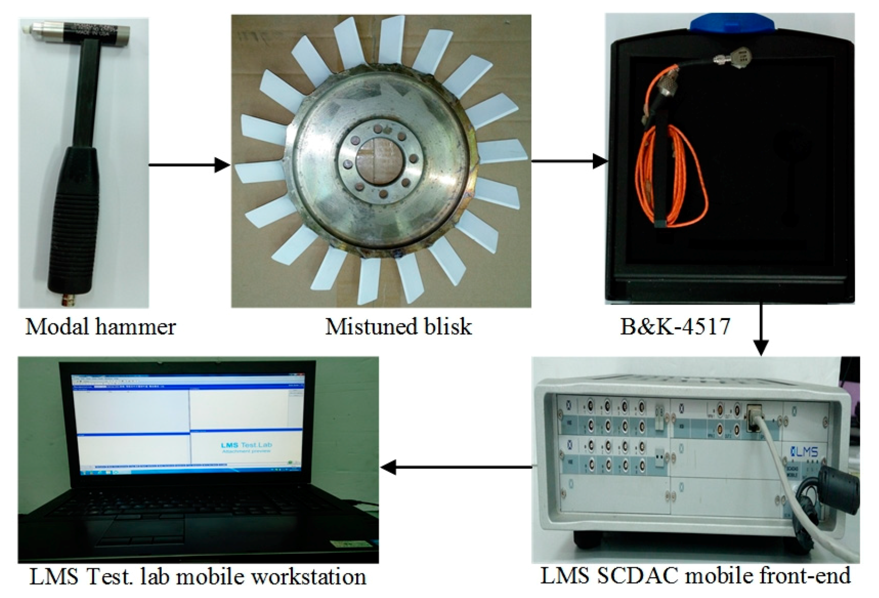
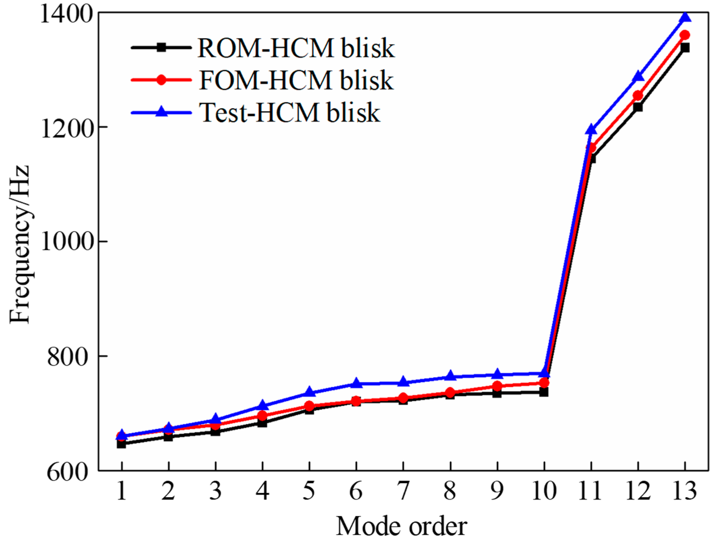
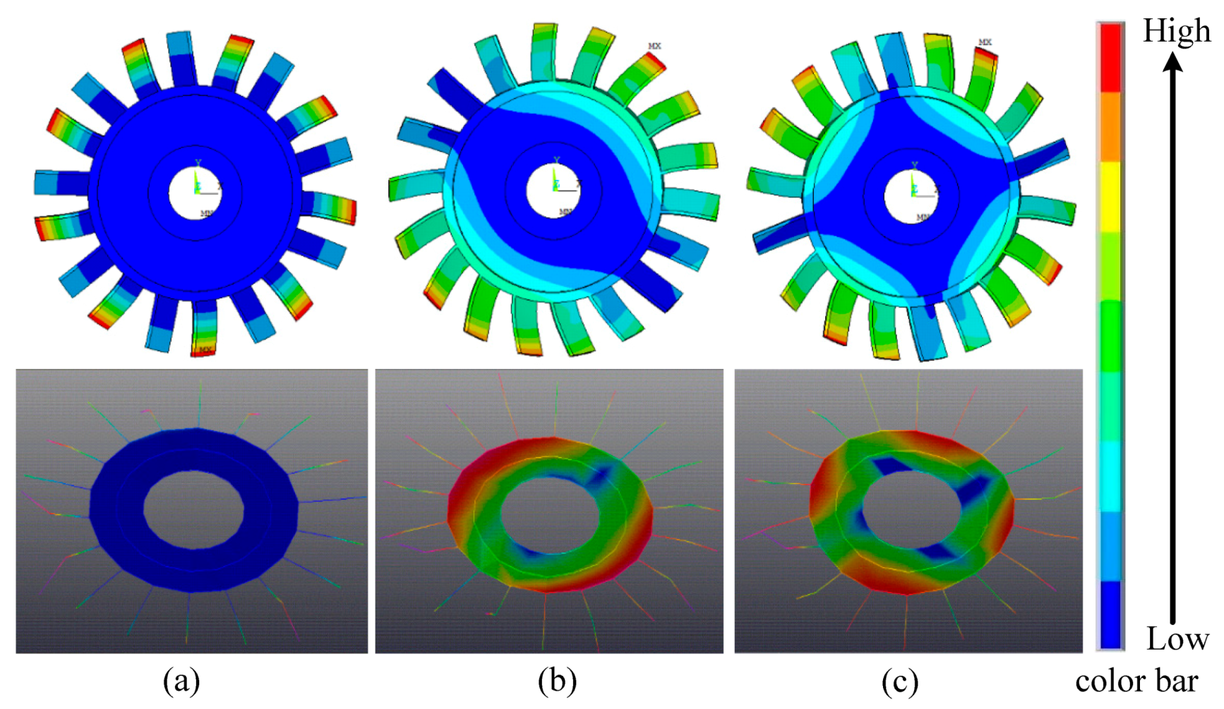
3.2. Mode Validation

In this research, the vibration characteristics of the HCM blisk were solved on the basis of the established FOM and modified ROM. As shown in Figure 5, the excitation force along the axial direction was loaded on the tip of all the blades whose amplitudes were 20N, and the excitation frequency ranges from 600 to 800Hz, and the pick-up point (or the location of accelerometer) was located on one blade root. In addition, the hammer-peening modal test for the HCM blisk was also carried out to solve the vibration characteristics for validating modified ROM, and the experimental details were expressed briefly: firstly, a group of impact (108) points were peened orderly by the PCB® modal hammer; next, the response signals were transferred to the LMS SCDAC® mobile front-end using one B&K®-4517 lightweight accelerometer, which was fixed on the blade root; finally, the data acquisition and analysis were conducted to extract natural frequencies and modal shapes (along the axial direction) in the PolyMAX® module.
Natural frequencies of the HCM blisk obtained by the modified ROM, the FOM and the experimental test were shown in Figure 6. It was observed clearly that the discrepancies of natural frequencies obtained by three different ways were inevitable, those were produced by the decreased number of DOFs of the modified ROM and the random perturbations in experimental conditions. However, the good consistency of the results among each other can be seen as well, especially for low-order modes. It should be noted that the computational accuracy of the modified ROM can be changed by selecting the number of modes.
Mode shapes of the HCM blisk when nodal diameter number n d = 0 , 1 , 2 obtained by the modified ROM and the test were shown in Figure 7. The blue zones represent the location that vibration amplitudes were nearly zero, the yellow and red zones indicate the location that vibration amplitudes were very large, and the green zones denote the location that vibration amplitudes fall in between. It reveals that the strong-coupling vibrations dominate the vibration types of the HCM blisk. It should be noted that the colors distributions of the modified ROM were similar to those of the test, which means the good correlation of both results.

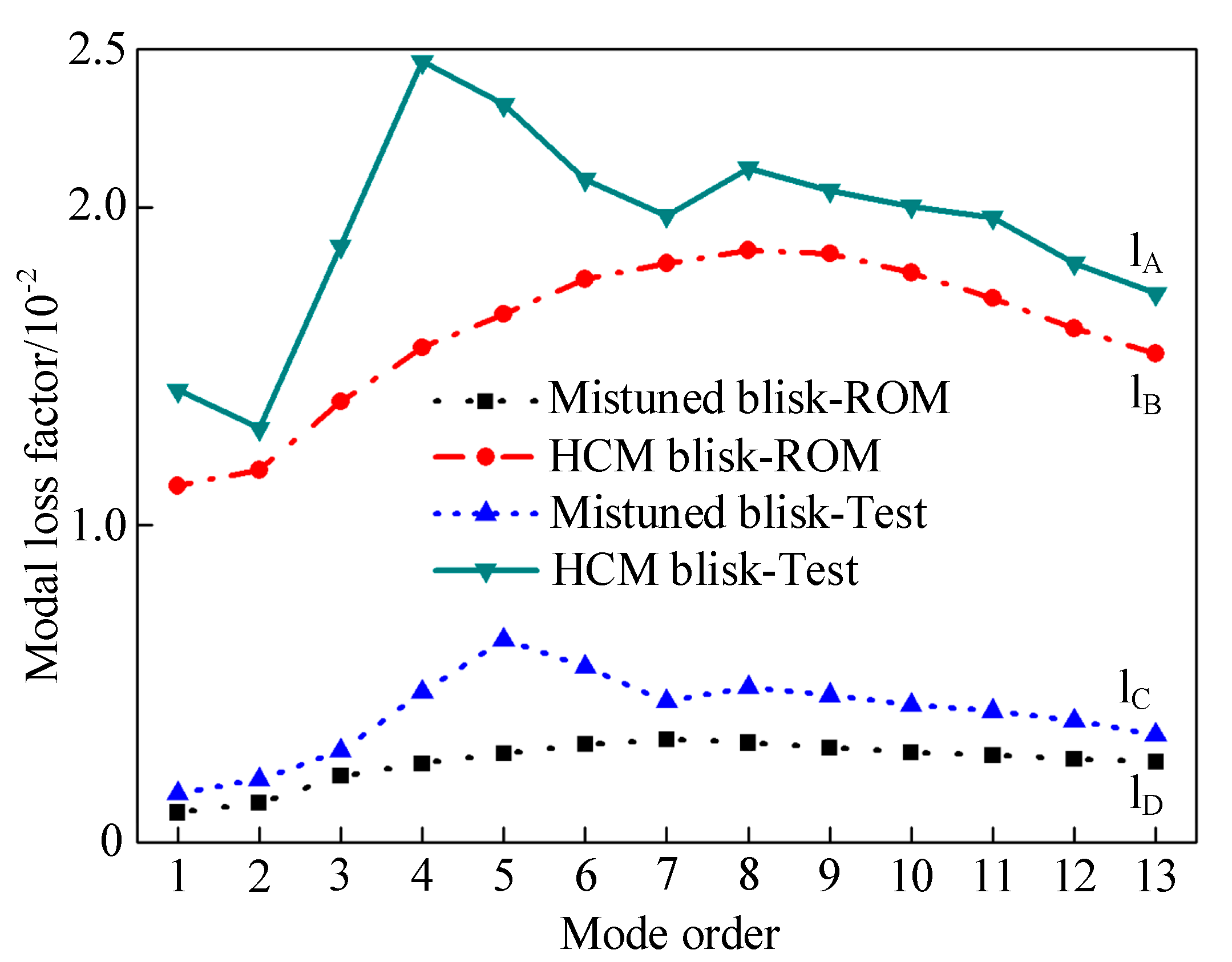
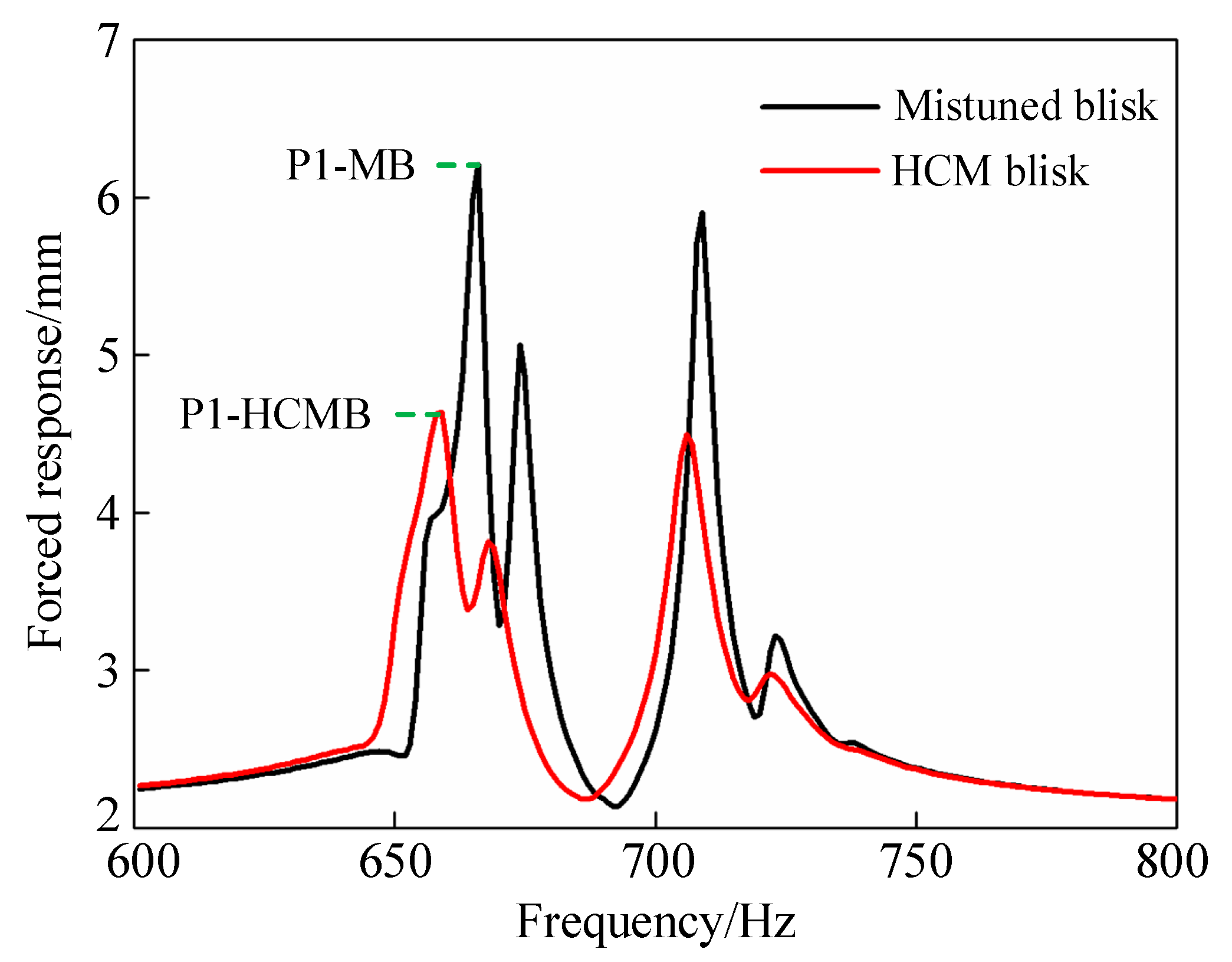
3.3. The Influence of Hard Coating

Natural frequencies of the mistuned blisk and the HCM blisk obtained by the modified ROM and the experimental test were listed in Table 3. Particularly, the change rates of natural frequencies were also calculated to investigate the specific influence of NiCoCrAlY+YSZ hard coating on the mistuned blisk. It reveals that the theoretical and experimental results decrease: natural frequencies obtained by the modified ROM vary within 2.65% generally, and those obtained from the experimental test range from 2.77% to 4.93% approximately. The above results and its variation mean the NiCoCrAlY + YSZ hard coating has a weak influence on natural frequencies.
Modal loss factors of the mistuned blisk and the HCM blisk obtained by the modified ROM and the experimental test were plotted in Figure 8. Due to the defect of existing damping theory and external perturbations in experimental conditions, modal loss factors of the mistuned blisk and the HCM blisk were captured with a large tolerance, that were described as l A l B and l C l D . However, the variation trends of both results were very similar. Moreover, modal loss factors of the HCM blisk increase with more than quadruple, expressed as l A 4 l C and l B 4 l D .The NiCoCrAlY + YSZ hard coating has a favorable effect on the damping capacities of the mistuned blisk.
Forced responses of the mistuned blisk and the HCM blisk obtained by modified ROM were shown in Figure 9. It can be found from vertical axis that resonant responses amplitudes of the mistuned blisk were suppressed apparently, which were expressed as ( P I - HCMB ) < ( P I - MB ) , I = 1 , 2 , 3 , 4 , . Moreover, the resonant frequencies of the mistuned blisk displayed in horizontal axis decrease slightly. In summary, the NiCoCrAlY + YSZ hard coating has a superior vibration reduction performance for the mistuned blisk without altering resonant frequencies significantly.

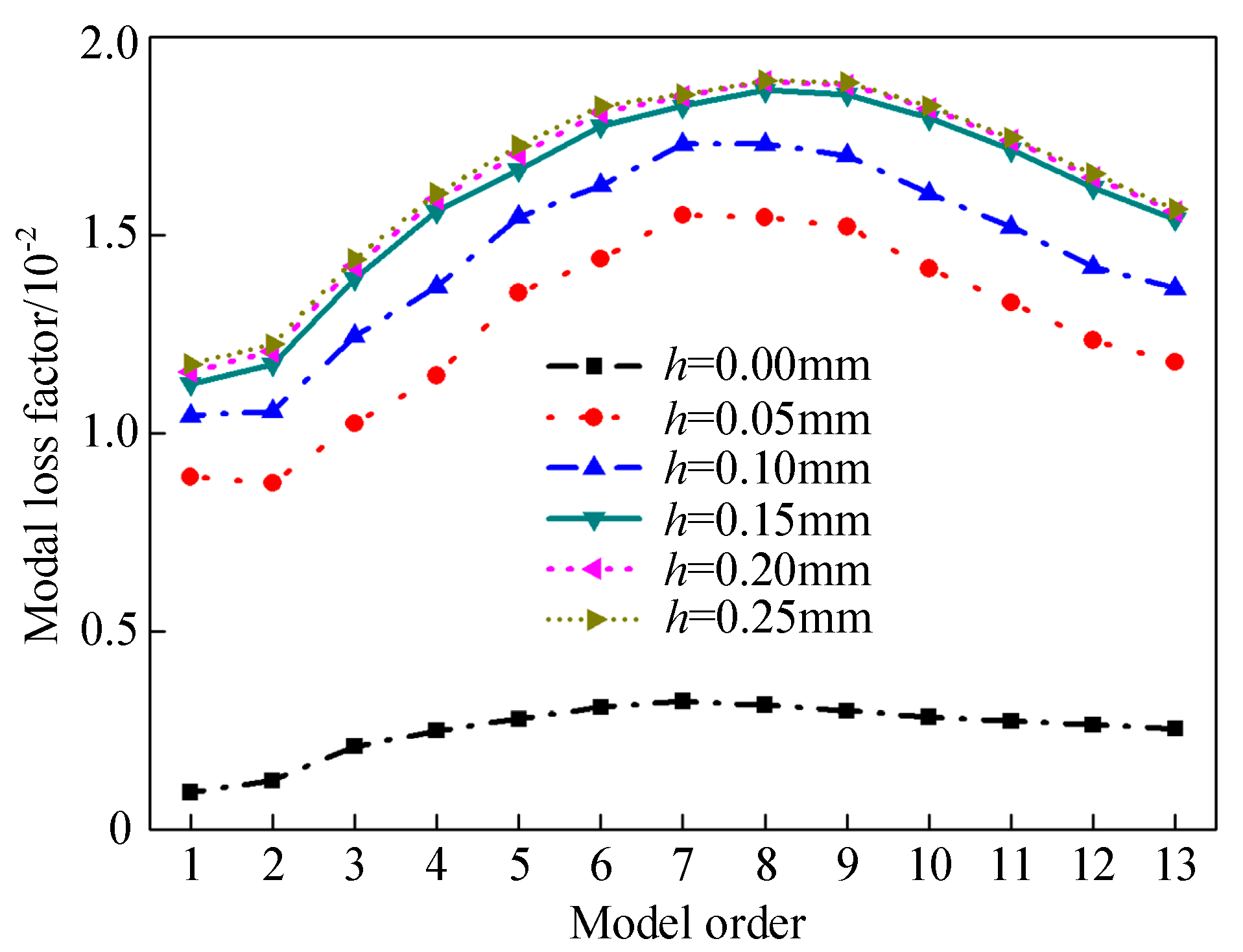
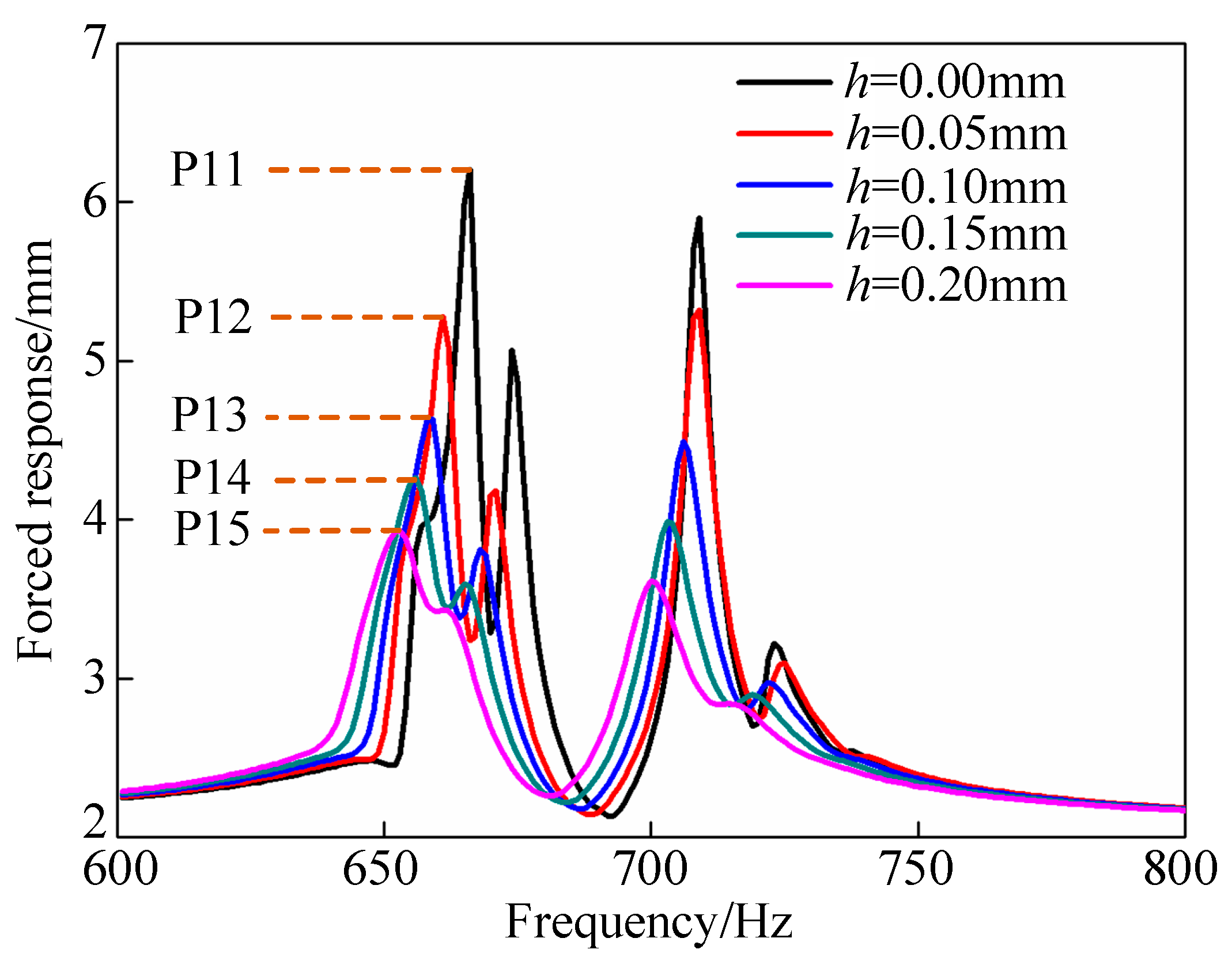
3.4. The Influence of Coating Thickness

Natural frequencies of the mistuned blisk with different coating thickness obtained by the modified ROM were listed in Table 4. And, the change rates corresponding to the maximum variation of coating thickness (between 0.00 and 0.25 mm) were also calculated here to investigate the specific influence of coating thickness. The results reveal that natural frequencies of the mistuned blisk decrease gradually when coating thickness thickens, and change rates vary from 2.20% to 3.61%. It indicates that the specific influence of coating thickness on natural frequencies of the mistuned blisk was not obvious particularly.
Modal loss factors of the mistuned blisk with different coating thickness obtained by the modified ROM were plotted in Figure 10. It reveals that modal loss factors of the mistuned blisk increase with the coating thickness. However, the variations of modal loss factors decrease gradually. That can be explained by the damping performance of hard coating and the rule of vibration energy transmission, respectively. Moreover, it seems that the variations of modal loss factors of the mistuned blisk were no more obvious when coating thickness reaches 0.20 mm, called the optimum thickness. It should be noted that the abovementioned unique change rule also can provide an important guidance for optimization design of vibration damping.
Forced response of the mistuned blisk verse different coating thickness obtained by the modified ROM were shown in Figure 11. It can be seen that all the resonant peaks of the mistuned blisk decrease with the increase of coating thickness, which means the increased damping capacities of the mistuned blisk generated by the variations of the NiCoCrAlY + YSZ hard coating. However, the decreased variations of all the resonant peaks of the mistuned blisk become smaller, such as ( P 1 4 P 15 ) < ( P 1 3 P 14 ) < ( P 12 P 13 ) < ( P 1 1 P 12 ) . It should be noted that the variation trends of all the resonant peaks of the mistuned blisk were similar to those of modal loss factors exactly.

4. Conclusions

To improve the working reliability of mistuned blisk, a damping strategy by damping hard coating was adopt to conduct passive vibration reduction, and vibration characteristics of the HCM blisk were investigated here. Moreover, a modified ROM of the HCM blisk combining the modified CMSM with proposed criterion named FDSD was developed to decrease the amount of calculation on the premise of ensuring the computational accuracy.
The benchmark of a mistuned blisk deposited NiCoCrAlY + YSZ hard coating on the blades was chosen to conduct vibration reduction analysis. The obtained natural frequencies and mode shapes were compared with the FOM and the experimental test, respectively. The comparisons revealed that the results obtained by three different methods were in good agreement, and the strong-coupled vibrations were the dominated modes type of the mistuned blisk.
The specific influence of the NiCoCrAlY + YSZ hard coating on mistuned blisk were investigated and discussed. The variations of the obtained results reveal that the NiCoCrAlY + YSZ hard coating has weak influence on natural frequencies, but the strong effect on the vibration damping capacities, and all the resonant peaks of the mistuned blisk can be suppressed remarkably without altering resonant frequencies significantly.
The specific influence of coating thickness on the mistuned blisk were also investigated for damping optimization. The obtained results reveal that the damping capacities of the mistuned blisk increase when coating thickness thickens. However, the change gradients of damping capacities decrease gradually. Specifically, when coating thickness reaches 0.25 mm, the damping capacities of hard coating were no more particularly obvious.

Supplementary Materials

Supplementary File 1

Author Contributions

Conceptualization, designed and performed the vibration experiments, formal analysis and editing this paper: F.G.; visualization and supervision: B.L.; project administration: X.L.

Funding

The authors were very grateful for financial support received from the Startup Foundation for Introducing Talent of NUIST Binjiang College (Grant No. 2019r007) and National Natural Science Foundations of China (Grant No. 51775092) and the Fundamental Research Funds for the Central Universities of China (Grant No. N170306002).

Acknowledgments

We acknowledge sincerely the financial support received from the NUIST Binjiang College and the technical support received from the Northeastern University of China. In addition, Feng Gao wants to thank the care and support from my families over the passed years.

Conflicts of Interest

The author(s) declare no potential conflicts of interest with respect to the research, the authorship and the publication of this paper.

References

  1. Bußmann, M.; Bayer, E. Market-oriented blisk manufacturing: A challenge for production engineering. In Proceedings of the First European Air and Space Conference (CEAS), Berlin, Germany, 10–13 September 2007. [Google Scholar]
  2. Younossi, O.; Arena, M.V.; Moore, R.M.; Lorell, M.A.; Mason, J.; Graser, J.C. Military Jet Engine Acquisition: Technology Basics and Cost-Estimating Approach Ology; RAND Corporation: Santa Monica, CA, USA, 2002. [Google Scholar]
  3. Duan, Y.; Zang, C.; Petrov, E.P. Forced response analysis of high-mode vibrations for mistuned bladed disks with effective reduced-order models. J. Eng. Gas Turbines Power 2016, 138, 112502. [Google Scholar] [CrossRef]
  4. Sinha, A. Reduced-order model of a bladed rotor with geometric mistuning. J. Turbomach. 2009, 131, 031007. [Google Scholar] [CrossRef]
  5. Klauke, T.; Kuhhorn, A.; Beirow, B.; Golze, M. Numerical Investigations of localized vibrations of mistuned blade integrated disks (blisks). J. Turbomach. 2009, 131, 031002. [Google Scholar] [CrossRef]
  6. Castanier, M.P.; Pierre, C. Modeling and analysis of mistuned bladed disk vibration: Current status and emerging directions. J. Propuls. Power 2006, 22, 384–396. [Google Scholar] [CrossRef]
  7. Zhao, P.F.; Zhang, Q.; Wu, J.; Zhang, D. Experimental study of dynamic characteristics of dry friction damping of turbine blade steel. Adv. Mater. Res. 2013, 690, 1979–1982. [Google Scholar] [CrossRef]
  8. Li, G.; Zhang, Q.; Zhao, W.; Zhou, Q.; Xie, Y. Dynamic Response Analysis of Blades with Damping Structures of Shroud and Snubber. In Proceedings of the First International Conference on Information Sciences, Machinery, Materials and Energy, Chongqing, China, 11–13 April 2015; Atlantis Press: Paris, France, 2015. [Google Scholar]
  9. He, B.; Ouyang, H.; Ren, X.; He, S. Dynamic response of a simplified turbine blade model with under-platform dry friction dampers considering normal load variation. Appl. Sci. 2017, 7, 228. [Google Scholar] [CrossRef]
  10. Pesaresi, L.; Salles, L.; Jones, A.; Green, J.S.; Schwingshackl, C.W. Modelling the nonlinear behavior of an under-platform damper test rig for turbine applications. Mech. Syst. Signal Process. 2017, 85, 662–679. [Google Scholar] [CrossRef]
  11. Laxalde, D.; Thouverez, F.; Sinou, J.J. Forced response analysis of blisks with friction ring dampers. J. Vib. Acoust. 2010, 132, 011013. [Google Scholar] [CrossRef]
  12. Baek, S.; Epureanu, B.I. Reduced-order modeling of bladed disks with friction ring dampers. J. Vib. Acoust. 2017, 139, 061011. [Google Scholar] [CrossRef]
  13. Ren, Z.; Atalla, N.; Ghinet, S. Optimization Based identification of the dynamic properties of linearly viscoelastic materials using vibrating beam technique. J. Vib. Acoust. 2011, 133, 041012. [Google Scholar] [CrossRef]
  14. Han, B.; Zhang, M.; Qi, C.; Cui, N.; Wang, Y. Characterization and friction-reduction performances of composite coating produced by laser cladding and ion sulfurizing. Mater. Lett. 2015, 150, 35–38. [Google Scholar] [CrossRef]
  15. Wei, S.; Pei, X.; Shi, B.; Shao, T.; Li, T.; Li, Y.; Xie, Y. Wear resistance and anti-friction of expansion cone with hard coating. Pet. Explor. Dev. 2016, 43, 326–331. [Google Scholar]
  16. Morita, T.; Inoue, K.; Ding, X.; Usui, Y.; Ikenaga, M. Effect of hybrid surface treatment composed of nitriding and DLC coating on friction-wear properties and fatigue strength of alloy steel. Mater. Sci. Eng. A 2016, 661, 105–114. [Google Scholar] [CrossRef]
  17. Stathopoulos, V.; Sadykov, V.; Pavlova, S.; Bespalko, Y.; Fedorova, Y.; Bobrova, L.; Salanov, A.; Ishchenko, A.; Stoyanovsky, V.; Larina, T.; et al. Design of functionally graded multilayer thermal barrier coatings for gas turbine application. Surf. Coat. Technol. 2016, 295, 20–28. [Google Scholar] [CrossRef]
  18. Gong, X.; Chen, R.; Wang, Q.; Wang, Y.; Zhang, N.; Zhang, Z.; Fu, H. Cyclic oxidation behavior and oxide scale adhesion of Al/NiCrAlY coating on pure titanium alloy. J. Alloy. Compd. 2017, 729, 679–687. [Google Scholar] [CrossRef]
  19. Zheng, H.; Li, B.; Tan, Y.; Li, G.; Shu, X.; Peng, P. Derivative effect of laser cladding on interface stability of YSZ@Ni coating on GH4169 alloy: An experimental and theoretical study. Appl. Surf. Sci. 2018, 427, 1105–1113. [Google Scholar] [CrossRef]
  20. Gao, Y.; Syed, J.A.; Lu, H.; Meng, X. Anti-corrosive performance of electropolymerized phosphomolybdic acid doped PANI coating on 304SS. Appl. Surf. Sci. 2016, 360, 389–397. [Google Scholar] [CrossRef]
  21. Wang, S.; Zhang, Z.; Gong, Y.; Nie, G. Microstructures and corrosion resistance of Fe-based amorphous/nanocrystalline coating fabricated by laser cladding. J. Alloy. Compd. 2017, 728, 1116–1123. [Google Scholar] [CrossRef]
  22. Bakhsheshi-Rad, H.; Hamzah, E.; Ismail, A.; Daroonparvar, M.; Yajid, M.; Medraj, M. Preparation and characterization of NiCrAlY/nano-YSZ/PCL composite coatings obtained by combination of atmospheric plasma spraying and dip coating on Mg-Ca alloy. J. Alloy. Compd. 2016, 658, 440–452. [Google Scholar] [CrossRef]
  23. Torvik, P.J.; Langley, B. Material Properties of Hard Coatings Developed for High Damping. In Proceedings of the 51st AIAA/SAE/A Sub-Structure Joint Propulsion Conference, Orlando, FL, USA, 27–29 July 2015. [Google Scholar]
  24. Sun, W.; Han, Q.; Qi, F. Optimal design of damping capacities for hard coating thin plate. Adv. Vib. Eng. 2013, 12, 179–192. [Google Scholar]
  25. Yang, Z.X.; Han, Q.K.; Jin, Z.H.; Qu, T. Solution of natural characteristics of a hard-coating plate based on Lindstedt—Poincaré perturbation method and its valedictions by FEM and measurement. Nonlinear Dyn. 2015, 81, 1207–1218. [Google Scholar] [CrossRef]
  26. Sun, W.; Liu, Y.; Du, G. Analytical modeling of hard-coating cantilever composite plate considering the material nonlinearity of hard coating. Math. Probl. Eng. 2015, 2015, 1–14. [Google Scholar] [CrossRef]
  27. Yang, Z.X.; Han, Q.K.; Chen, Y.G.; Jin, Z.H. Nonlinear harmonic response characteristics and experimental investigation of cantilever hard-coating plate. Nonlinear Dyn. 2017, 236, 500–538. [Google Scholar] [CrossRef]
  28. Sun, W.; Liu, R. Damping optimization of hard-coating thin plate by the modified modal strain energy method. Coatings 2017, 7, 32. [Google Scholar] [CrossRef]
  29. Sun, W.; Liu, Y. Vibration analysis of hard-coated composite beam considering the strain dependent characteristic of coating material. Acta Mech. Sin. 2016, 32, 731–742. [Google Scholar] [CrossRef]
  30. Sun, W.; Wang, Z.; Zhu, M.; Du, G. Identifying the mechanical parameters of hard coating with strain dependent characteristic by an inverse method. Shock Vib. 2015, 2015, 1–15. [Google Scholar] [CrossRef]
  31. Li, H.; Sun, W.; Zhu, M.; Xue, P. Experimental Study on the influence on vibration characteristics of thin cylindrical shell with hard coating under cantilever boundary condition. Shock Vib. 2017, 2017, 1–23. [Google Scholar] [CrossRef]
  32. Zhang, Y.; Sun, W.; Yang, J. A new finite element formulation for nonlinear vibration analysis of the hard-coating cylindrical shell. Coatings 2017, 7, 70. [Google Scholar] [CrossRef]
  33. Sun, W.; Zhu, M.; Wang, Z. Free vibration analysis of a hard-coating cantilever cylindrical shell with elastic constraints. Aerosp. Sci. Technol. 2017, 63, 232–244. [Google Scholar] [CrossRef]
  34. Yen, H.Y. New Analysis and Design Procedures for Ensuring Gas Turbine Blades and Adhesive Bonded Joints Structural Integrity and Durability. Ph.D. Thesis, Aeronautical and Astronautical Engineering. The Ohio State University, Columbus, OH, USA, 2000. [Google Scholar]
  35. Sun, J.; Kari, L. Coating methods to increase material damping of compressor blades: Measurements and Modeling. In Proceedings of the ASME Turbo Expo 2010: Power for Land, Sea, and Air, Glasgow, UK, 14–18 June 2010; pp. 1157–1165. [Google Scholar]
  36. Filippi, S.; Torvik, P.J. A methodology for predicting the response of blades with nonlinear coatings. J. Eng. Gas Turbines Power 2011, 133, 042503. [Google Scholar] [CrossRef]
  37. Zhou, B.; Thouverez, F.; Lenoir, D. An adaptive control strategy based on passive piezoelectric shunt techniques applied to mistuned bladed disks. J. Comput. Appl. Math. 2013, 246, 289–300. [Google Scholar] [CrossRef]
  38. Yuan, J.; Allegri, G.; Scarpa, F.; Rajasekaran, R.; Patsias, S. Probabilistic dynamics of mistuned bladed disc systems using subset simulation. J. Sound Vib. 2015, 350, 185–198. [Google Scholar] [CrossRef]
  39. Yuan, J.; Allegri, G.; Scarpa, F.; Patsias, S.; Rajasekaran, R. A novel hybrid Neumann expansion method for stochastic analysis of mistuned bladed discs. Mech. Syst. Signal Process. 2016, 72, 241–253. [Google Scholar] [CrossRef] [Green Version]
  40. Yuan, J.; Scarpa, F.; Allegri, G.; Titurus, B.; Patsias, S.; Rajasekaran, R. Efficient computational techniques for mistuning analysis of bladed discs: A review. Mech. Syst. Signal Process. 2017, 87, 71–90. [Google Scholar] [CrossRef] [Green Version]
  41. Bisegna, P.; Caruso, G. A Continuous model for the dynamical analysis of mistuned bladed rotors. Int. J. Rotating Mach. 2012, 2012, 1–10. [Google Scholar] [CrossRef] [Green Version]
  42. Najafi, A.; Ghazavi, M.-R.; Jafari, A.-A. Stability and hamiltonian hopf bifurcation for a nonlinear symmetric bladed rotor. Nonlinear Dyn. 2014, 78, 1049–1064. [Google Scholar] [CrossRef]
  43. Rivas-Guerra, A.J.; Mignolet, M.P. Local/Global effects of mistuning on the forced response of bladed disks. J. Eng. Gas Turbines Power 2004, 126, 131–141. [Google Scholar] [CrossRef]
  44. Hurty, W.C. Dynamic analysis of structural systems using component modes. AIAA J. 1965, 3, 678–685. [Google Scholar] [CrossRef]
  45. Craig, R.R.; Bampton, M.C.C.; Craig, J.R.R. Coupling of substructures for dynamic analyses. AIAA J. 1968, 6, 1313–1319. [Google Scholar] [CrossRef]
  46. Craig, R.R. Structural Dynamics: An Introduction to Computer Methods; John Wiley & Sons Inc.: Hoboken, NJ, USA, 1994. [Google Scholar]
  47. Irretier, H. Spectral analysis of mistuned bladed disk assemblies by component mode synthesis. Vib. Bl. Disk Assem. 1983, 115–125. [Google Scholar]
  48. Craig, R.R.; Chang, C.-J. Free-interface methods of substructure coupling for dynamic analysis. AIAA J. 1976, 14, 1633–1635. [Google Scholar] [CrossRef]
  49. Craig, R.R.; Chang, C.J. Substructure Coupling for Dynamic Analysis and Testing; NASA: Washington, DC, USA, 1977.
  50. Bladh, R.; Castanier, M.P.; Pierre, C. Component-mode-based reduced order modeling techniques for mistuned bladed disks-part I: Theoretical models. J. Eng. Gas Turbines Power 2001, 123, 89–99. [Google Scholar] [CrossRef]
  51. Bladh, R.; Castanier, M.P.; Pierre, C. Component-mode-based reduced order modeling techniques for mistuned bladed disks-part II: Application. J. Eng. Gas Turbines Power 2001, 123, 100–108. [Google Scholar] [CrossRef]
  52. Yang, M.-T.; Griffin, J.H. A reduced order model of mistuning using a subset of nominal system modes. J. Eng. Gas Turbines Power 1999, 123, 893–900. [Google Scholar] [CrossRef]
  53. Hohl, A.; Wallaschek, J. A method to reduce the energy localization in mistuned bladed disks by application-specific blade pattern arrangement. J. Eng. Gas Turbines Power 2016, 138, 092502. [Google Scholar] [CrossRef]
  54. Yang, M.-T.; Griffin, J.H. A normalized modal eigenvalue approach for resolving modal interaction. J. Eng. Gas Turbines Power 1997, 119, 647–650. [Google Scholar] [CrossRef]
  55. Beirow, B.; Giersch, T.; Kühhorn, A.; Nipkau, J. Optimization-aided forced response analysis of a mistuned compressor blisk. J. Eng. Gas Turbines Power 2015, 137, 012504. [Google Scholar] [CrossRef]
  56. Petrov, E.P.; Sanliturk, K.Y.; Ewins, D.J. A new method for dynamic analysis of mistuned bladed disks based on the exact relationship between tuned and mistuned systems. J. Eng. Gas Turbines Power 2002, 124, 586–597. [Google Scholar] [CrossRef]
  57. Feiner, D.M.; Griffin, J.H. A fundamental model of mistuning for a single family of modes. J. Turbomach. 2002, 124, 597–605. [Google Scholar] [CrossRef]
  58. Chan, Y.J.; Ewins, D.J. Prediction of vibration response levels of mistuned integral bladed disks (blisks): Robustness studies. J. Turbomach. 2012, 134, 044501. [Google Scholar] [CrossRef]
  59. Kaneko, Y.; Nakanishi, R.; Mori, K.; Ohyama, H. Study on Vibration characteristics of mistuned bladed disk (vibration response analysis by reduced model fmm). Trans. Jpn. Soc. Mech. Eng. Ser. C 2013, 7, 328–342. [Google Scholar] [CrossRef] [Green Version]
  60. Yang, M.-T.; Griffin, J.H. A Reduced order approach for the vibration of mistuned bladed disk assemblies. J. Eng. Gas Turbines Power 1997, 119, 161–167. [Google Scholar] [CrossRef]
  61. Lim, S.-H.; Bladh, R.; Castanier, M.P.; Pierre, C. Compact, generalized component mode mistuning representation for modeling bladed disk vibration. AIAA J. 2007, 45, 2285–2298. [Google Scholar] [CrossRef]
  62. McGee, O.G.; Fang, C.; El-Aini, Y. A reduced-order meshless energy model for the vibrations of mistuned bladed disks—Part I: Theoretical basis. J. Turbomach. 2013, 135, 061001. [Google Scholar] [CrossRef]
  63. Fang, C.; McGee, O.G.; El Aini, Y. A reduced-order meshless energy model for the vibrations of mistuned bladed disks—Part II: Finite element benchmark comparisons. J. Turbomach. 2013, 135, 061002. [Google Scholar] [CrossRef]
  64. Zheng, H.; Tan, X.; Cai, C. Damping analysis of beams covered with multiple PCLD patches. Int. J. Mech. Sci. 2006, 48, 1371–1383. [Google Scholar] [CrossRef]
  65. Curà, F.; Mura, A.; Scarpa, F. Modal strain energy based methods for the analysis of complex patterned free layer damped plates. J. Vib. Control 2012, 18, 1291–1302. [Google Scholar] [CrossRef]
  66. Yoon, Y.C.; Kim, K.H.; Lee, S.H. Dynamic particle difference method for the analysis of proportionally damped system and cracked concrete beam. Int. J. Fract. 2017, 203, 237–262. [Google Scholar] [CrossRef]
  67. Lázaro, M.; Pérez-Aparicio, J.L.; Epstein, M. Computation of eigenvalues in proportionally damped viscoelastic structures based on the fixed-point iteration. Appl. Math. Comput. 2012, 219, 3511–3529. [Google Scholar] [CrossRef] [Green Version]
  68. Ma, F.; Morzfeld, M. A General methodology for decoupling damped linear systems. Procedia Eng. 2011, 14, 2498–2502. [Google Scholar] [CrossRef] [Green Version]
Figure 1. The model of the mistuned blisk and hard-coating mistuned (HCM) blisk.
Coatings 09 00812 g001
Figure 2. The solution procedure of forced response of the HCM blisk by the modified reduced-order models (ROM).
Coatings 09 00812 g002
Figure 3. The fundamental solution procedure for solving frequency difference and its standard deviation (FDSD) criterion.
Coatings 09 00812 g003
Figure 4. Physical pictures of the mistuned blisk and experimental devices.
Coatings 09 00812 g004
Figure 5. Hard-coating mistuned blisk and its experimental model established in LMS. Hard-coating mis tuned blisk; experimental model established in LMS.
Coatings 09 00812 g005
Figure 6. Natural frequencies of the HCM blisk obtained by the modified ROM, the full-order model (FOM) and the test.
Coatings 09 00812 g006
Figure 7. Mode shapes of the HCM blisk obtained by the modified ROM and the test: (a) n d = 0 ; (b) n d = 1 ; (c) n d = 2 .
Coatings 09 00812 g007
Figure 8. Modal loss factors of the mistuned blisk and the HCM blisk obtained by the modified ROM and the test.
Coatings 09 00812 g008
Figure 9. Forced response of the mistuned blisk and the HCM blisk obtained by the modified ROM.
Coatings 09 00812 g009
Figure 10. Modal loss factors of the mistuned blisk verse different coating thickness.
Coatings 09 00812 g010
Figure 11. Forced responses of the mistuned blisk verse different coating thickness.
Coatings 09 00812 g011
Table 1. Geometrical parameters of the hard-coating mistuned (HCM) blisk.
DiskHard-Coating Blades
Inner radius of hub50 mmHeight of blade50 mm
Outer radius of hub80 mmWidth of blade25 mm
Thickness of hub19 mmThickness of blade3 mm
Inner radius of rim182 mmNumber of blade18
Outer radius of rim200 mm------
Thickness of rim20 mmSingle coating thickness0.1 mm
Thickness of sternum7 mmCoating area100%, both sides
Table 2. Mechanical parameters of the mistuned blisk and hard coating.
CatalogMistuned BliskHard Coating
Material typeQ235-A (F) steelNiCoCrAlY + YSZ
Young’s modulus (GPa)20854.5
Mass density (kg/m3)78605600
Loss factor0.00060.0212
Poisson’s ratio0.300.30
Table 3. Natural frequencies of the mistuned blisk and the HCM blisk obtained by the modified reduced-order models (ROM) and test /Hz.
Mode OrderModified ROMTest
Mistuned Blisk/HzHCM Blisk/HzChange Rate/%Mistuned Blisk/HzHCM Blisk/HzChange Rate/%
1655.99647.39−1.33693.07660.59−4.92
2668.38659.49−1.35705.80673.18−4.85
3676.34668.15−1.23716.54689.09−3.98
4690.33683.85−0.95732.30712.57−2.77
5714.70706.01−1.23759.01735.87−3.14
6728.95720.51−1.17775.04751.22−3.17
7731.27722.67−1.19778.49753.72−3.29
8741.11732.28−1.21789.87763.98−3.39
9743.69735.07−1.17793.59767.14−3.45
10745.74737.37−1.14796.76769.79−3.50
111162.901144.60−1.601237.861193.76−3.69
121265.401234.10−2.541347.001287.14−4.65
131373.201337.70−2.651458.731390.19−4.93
Table 4. Natural frequencies of the mistuned blisk with different coating thickness.
Mode OrderCoating Thickness (mm)/Natural Frequencies (Hz)Maximum Change Rate/%
h = 0.0h = 0.05h = 0.10h = 0.15h = 0.20h = 0.25
1655.99649.78647.39644.66641.65638.40−2.76
2668.38661.76659.49656.83653.85650.60−2.73
3676.34670.41668.15665.49662.49659.20−2.60
4690.33685.79683.85681.43678.60675.44−2.20
5714.70708.52706.00703.09699.85696.33−2.64
6728.95723.06720.51717.55714.24710.65−2.58
7731.27725.28722.67719.66716.31712.68−2.61
8741.11734.97732.28729.18725.75722.03−2.64
9743.69737.75735.07731.97728.54724.82−2.60
10745.74740.03737.37734.29730.86727.14−2.56
111162.901147.401144.601141.701138.601137.40−2.24
121265.401237.301234.101230.801227.401223.90−3.39
131373.201341.701337.701333.701329.501325.30−3.61

