1. Introduction
In recent years, next-generation technology has become preoccupied with eco-friendly and economic factors, and many studies in various fields have focused on improving efficiency. Typically, the aerospace industry focuses on engine efficiency, including advanced gas turbines and aircraft engines [
1,
2]. Among the methods of improving the efficiency of an engine, much research has been conducted on increasing the operating temperatures of materials [
1,
2]. When selecting a new high temperature material, various factors such as melting point, density and oxidation resistance should be considered. For example, Ni-based Haynes 230 and/or Inconel 718 alloys, which have been used as turbine engine materials for decades, have an operating temperature below ~1100 °C [
3]. However, by reaching a service temperature of ~1300 °C without a cooling system, the output power of an engine can be improved by about 50%. In this regard, Mo-based alloys have been considered as alternatives [
2]. Many studies have been conducted on high-temperature alloys with designs that can enhance the material properties [
4,
5,
6,
7,
8]. For example, it has been documented that Mo–Si–B alloys showed excellent high temperature strength. Much research has been carried out on Mo–Si–B alloys of Mo
3Si (A15) + Mo (ss) + Mo
5SiB
2 (T2) phases by adding Si and B to the ductile Mo component to increase strength at high temperatures [
2,
9,
10,
11]. While Mo-based alloys showed excellent mechanical properties, attempts were made to lower their densities. One route for adjusting density was to design Mo–Nb-based alloys, since the density of Nb is lower than that of Mo. Research has been conducted on Nb–Mo-based alloys with lowered densities and improved mechanical properties at room temperature [
12,
13]. K. Chattopadhyay et al. investigated the microstructure and mechanical properties of Nb–Si–B alloys [
14]. N. Takata et al. investigated the microstructures of Nb–Mo–Si–B alloys in Bcc/T1/T2 three phases by fixing the Nb content at 32.6 at.% and then adjusting the Si and B contents [
15]. J.M. Byun et al. tried to improve the mechanical properties by adding Nb to a Mo–Si–B alloy with powder metallurgy, and compared the manufactured Nb–Mo–Si–B alloy with a Mo–Si–B counterpart [
13].
While they have high melting points and excellent strength at high temperatures [
2,
12,
13,
16], the alloys are known to show serious defects upon exposure to high temperatures under ambient atmosphere [
4,
16,
17]. For Mo-based alloys, the Mo component is known to have poor oxidation resistance as a result of the formation of volatile oxides MoO
3 (g) at temperatures above about 500 °C [
16,
17,
18,
19]. When Mo-based alloys were exposed to high temperatures in air, they usually disintegrated. For Mo–Si–B alloys, while the oxidation behavior is enhanced due to the formation of borosilicate, the surface still needs protection. In addition, Nb-based alloys also have been reported to have poor oxidation behavior due to Nb
2O
5 (s) oxides having non-protective properties at high temperatures, and because oxidation rapidly forms porous layers instead of continuous oxide layers [
20,
21,
22]. In order to enhance the oxidation behavior, many studies have been reported, such as pack cementation, spray coatings, plasma coatings, etc. [
16,
23,
24]. Among the examined coating routes, pack cementation processing appears to be an effective manner to produce oxidation resistant coatings. The pack cementation process can provide mass production and ensure high bond strength between the coating materials and substrates. Further, complex-shaped component parts can be uniformly coated, since the coating method adopts gas diffusion to substrates [
16].
A number of studies have been conducted to improve oxidation resistance by forming SiO
2 or Al
2O
3 oxide on the surface in a high temperature oxidation environment with pack cementation coatings [
16,
17,
20,
21,
25]. K. Choi et al. discussed the growth and oxidation behavior of coating layers after Si pack cementation coatings on Mo–3Si–1B (wt.%) alloys [
16]. K. Choi et al. also investigated the oxidation behavior under the condition of 1350 °C after forming a MoSi
2-silicide layer on the surface of TZM alloys. In addition, the oxidation behavior was discussed in terms of the diffusion pathway and microstructure changes in the Mo–Si–O system [
17]. J. Cheng et al. investigated the microstructures and oxidation behavior of the coating layers at 1100 °C after forming silicide layers in Nb–Si–B alloys [
20,
21]. Y. Liu et al. investigated the oxidation behavior in terms of microstructures by controlling the Nb:Mo ratio in the Nb–Mo–Si–B system [
26].
It has been reported that after pack cementation coatings, the oxidation resistance increased for Mo-based alloys at high temperatures. For example, when Mo–Si–B alloys were coated via a Si pack cementation process, a MoSi2 layer was produced at the surface, and the coated alloy showed excellent oxidation resistance up to about 1400 °C. At the same time, when Nb–Si–B alloys were Si pack coated, the NbSi2 layer was produced at the surface. It should be noted that the oxidation resistance of the coated NbSi2 layer was not excellent due to the formation of non-protective oxides, indicating that an optimum composition of the coated layer should be determined. Further, since the surface coating layer of (Mo or Nb) Si2 is directly affected by the substrate composition, various substrate compositions should be investigated; this is the primary objective of this study.
In this study, in order to identify the optimal composition for the coating layer, various Mo–Nb alloys which directly affect the surface coating layer were investigated. After Si pack cementation coatings were applied to Nb–Mo alloys, oxidation resistance at 1200 °C (that is, a higher temperature that that previously reported for the oxidation limits of NbSi2-coated alloys) was investigated from the viewpoint of microstructures. Based on the results, we offer guidelines for the appropriate Nb:Mo ratio of substrates for potential Mo and Nb-based alloys at 1200 °C.
3. Results and Discussion
Each Nb
xMo
y alloy prepared by arc-melting was identified by EDS analysis to determine the atomic percentage of the compositions (in
Table 1).
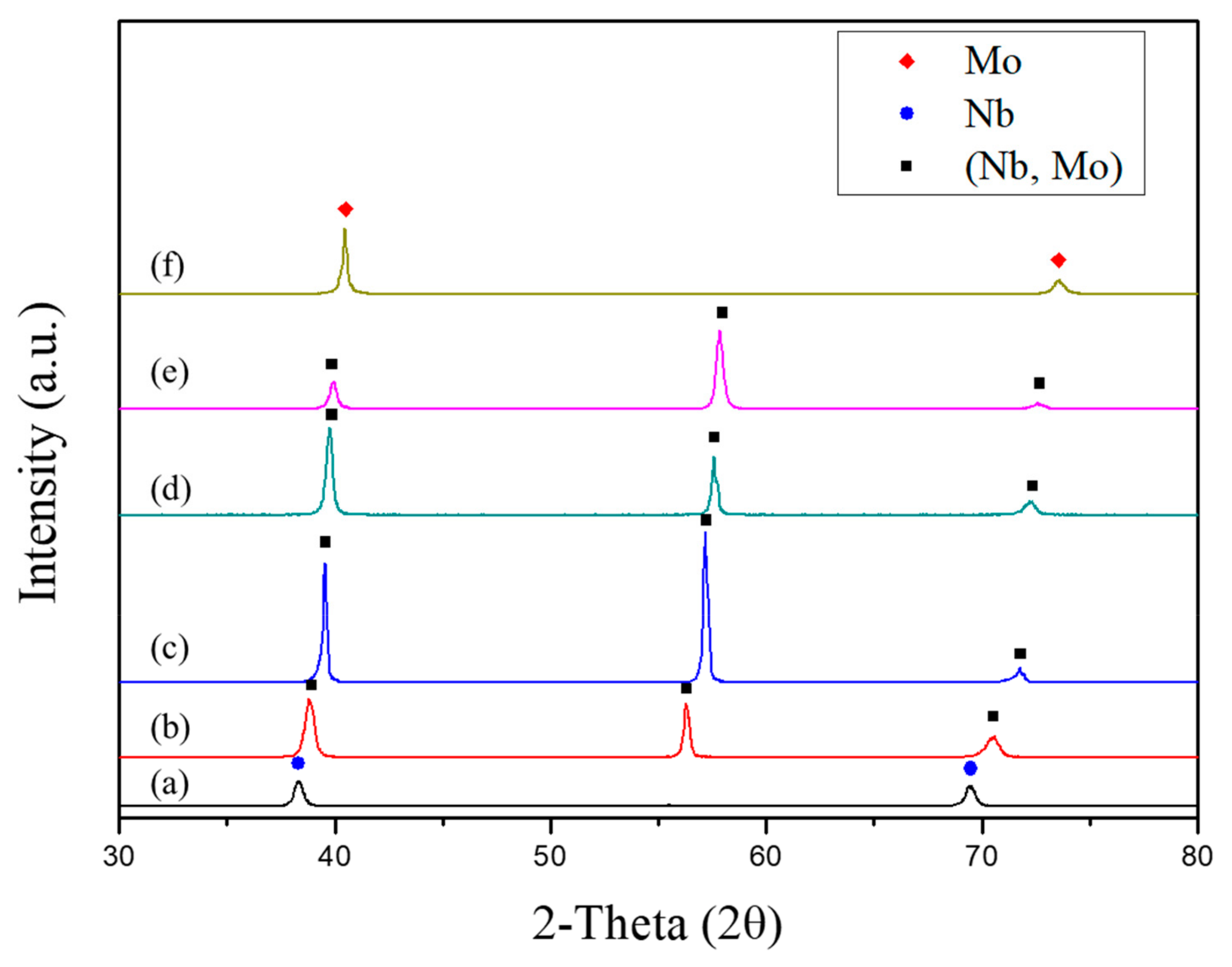
Figure 1 shows the results of the XRD patterns of the fabricated Nb
xMo
y alloys.
Figure 1 shows the XRD results of Alloy 1 (Nb), Alloy 2 (Nb
73.6Mo
26.4), Alloy 3 (Nb
51.2Mo
48.8), Alloy 4 (Nb
35.1Mo
64.9), Alloy 5 (Nb
25.7Mo
74.3), and Alloy 6 (Mo), respectively. As the Mo content increases, the XRD peak shifts to the right. It appears that the peak shift is a well-known effect which occurs due to lattice parameter difference. While an analysis of the peak shift is needed, a detailed analysis will be shown elsewhere.
Figure 2 shows SEM BSE images of a cross section of the Si-coated Nb
xMo
y alloys heated at 1100 °C for 24 h. When the substrate was pure Nb (
Figure 2a), the coated layer was identified as NbSi
2 with a thickness of ~27 µm; another coated layer was identified as MoSi
2 with a thickness of ~39 µm at the surface (
Figure 2f). However, when the composition of the substrate was changed, the coating layer composition was different. For the Nb–Mo alloys (Alloys 2, 3, 4, and 5), a mixture of Nb and Mo silicide was identified, i.e., (Nb
x, Mo
y)Si
2. Furthermore, another (Nb
x, Mo
y)
5Si
3 layer formed between the substrate and the outer (Nb
x, Mo
y)Si
2. Notably, in Alloy 3 (Nb
51.2Mo
48.8), Alloy 4 (Nb
35.1Mo
64.9), and Alloy 5 (Nb
25.7Mo
74.3), the (Nb
x, Mo
y)
5Si
3 phases were distributed in the (Nb
x, Mo
y)Si
2 layer. The (Nb
x, Mo
y)
5Si
3 phases of Alloy 5 (Nb
25.7Mo
74.3) were generally distributed, but the (Nb
x, Mo
y)
5Si
3 phases of Alloy 3 (Nb
51.2Mo
48.8) and Alloy 4 (Nb
35.1Mo
64.9) were distributed close to the substrate.
In fact, since the outer coating layer is significant for surface protection during oxidant exposure, the outer (Nb
x, Mo
y)Si
2 layer was specially focused.
Table 2 shows the results of the EDS measurements of the outer (Nb
x, Mo
y)Si
2 coating layer. The Nb:Mo ratio in the (Nb
x, Mo
y)Si
2 layer is shown for the Si-pack-coated alloys. The EDS measurements of the NbSi
2 coating layer in
Figure 2a and the MoSi
2 coating layer in
Figure 2f were confirmed to be about Nb:Si = 34.8:65.2 (at.%) and about Mo: Si = 35.3:64.7 (at.%), respectively. Also, the EDS measurements of the (Nb
x, Mo
y)Si
2 coating layers in
Figure 2b–e were confirmed to be about Nb:Mo:Si = 26.9:8.5:64.6 (at.%), 18.9:16.4:64.7 (at.%), 12.5:23.1:64.4 (at.%), and 9.0:27.4:63.6 (at.%), respectively. Additionally, the Nb:Mo ratios in the silicide coating layers of each specimen were about 100.0/0, 76.0/24, 53.5/46.5, 34.8/64.2, 24.8/75.2, and 0/100.0 (at.%), indicating that the outer coating layer may be expressed as (Nb
x, Mo
y)Si
2.
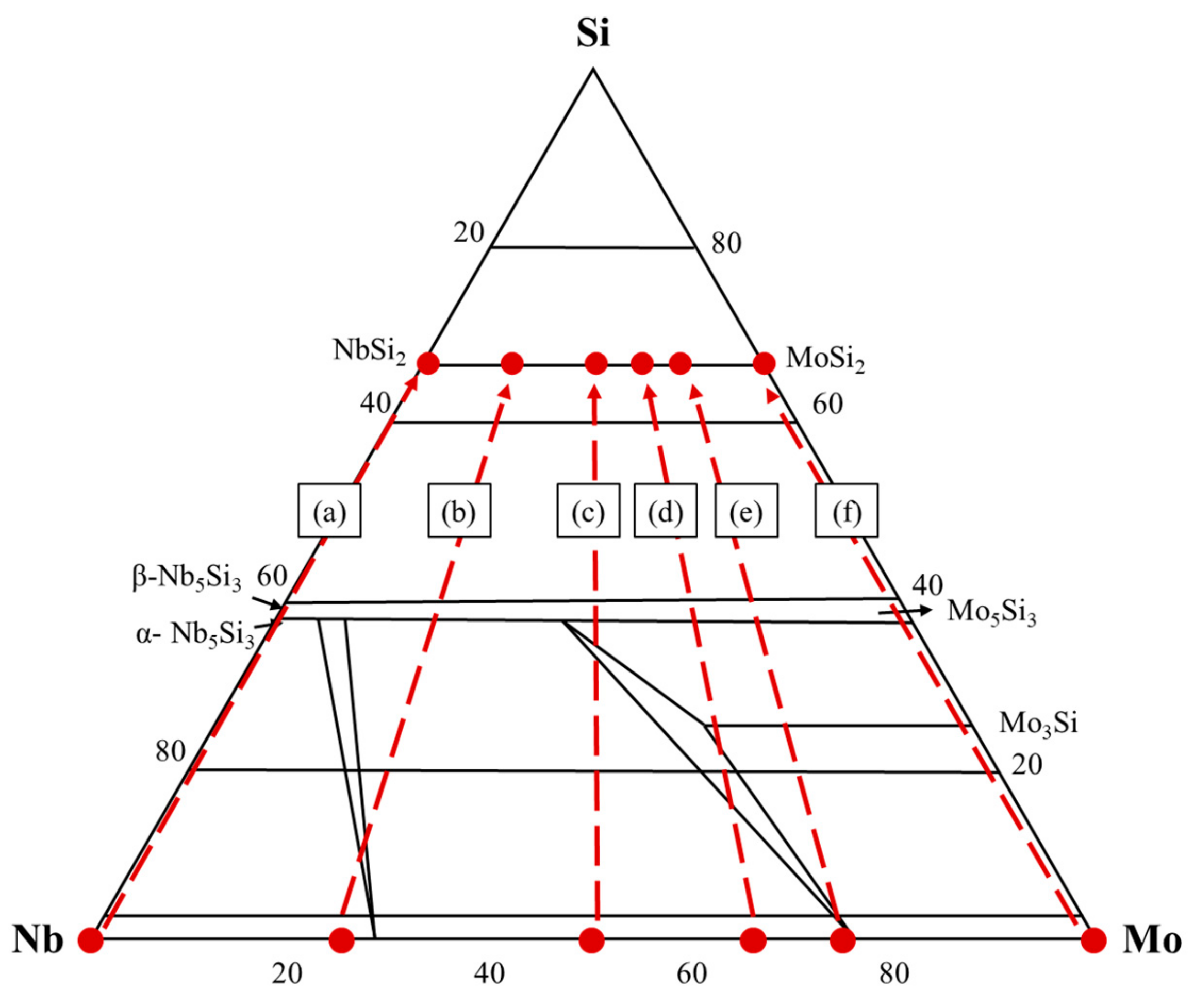
Figure 3 shows the compositions of the substrates and the coated layer marked in the Nb–Mo–Si ternary phase diagram. Since the isothermal diagram was reported only both at 800 °C and 1300 °C, a schematic isothermal phase diagram was presented to show the locations of the present alloy compositions and the coated layer compositions. The dotted arrows do not show a real diffusion pathway, but indicate that the coated layer compositions are closely related to the substrate compositions. As shown in
Figure 3, the coated layer of (Nb
x, Mo
y)Si
2 was changed with respect to the substrate compositions. It should be noted that the absence of the (Nb
x, Mo
y)
5Si
3 phase in some alloys is possibly due to nucleation difficulties of resolution limitation, as indicated in previous papers [
2,
16]. Again, the dots in the phase diagram are from the EDS measurements from
Table 1 and
Table 2. In turn, the present observations can be used in the design of coating layers with control of the substrate.
Figure 4 shows the XRD patterns of Si-pack-coated specimens at 1100 °C for 24 h. When the alloy composition of Nb increased from 100 to 0 weight percent, the peak was changed. For example, with Alloy 1 (Nb), only NbSi
2 peaks were observed. With Alloy 6 (Mo), only MoSi
2 peaks were identified. However, when the substrate composition was between Nb and Mo, peaks of the (Nb
x, Mo
y)Si
2 and (Nb
x, Mo
y)
5Si
3 phase layers were detected. Further analysis will be given elsewhere.
As mentioned, Nb-based alloys and/or NbSi
2-coatedNb-based alloys do not maintain their original shape during oxidation exposure at 1200 °C [
21], in contrast to MoSi
2-coated Mo-based alloys [
16]. In order to examine the oxidation resistance, oxidation tests were carried out at 1200 °C.
Figure 5 shows the appearance of the Si-pack-coated specimens before and after the oxidation tests at 1200 °C for 6 h. After the oxidation tests, the Si-pack-coated Alloy 1 (Nb) and Alloy 2 (Nb
73.6Mo
26.4) appeared to be white due to the formation of SiO
2 + Nb
2O
5 on the surface. Notably, the surface oxide was peeled off from the surface, showing serious defects. Also, it can be seen that Alloy 3 (Nb
51.2Mo
48.8) shows cracks on the surface after oxidation tests, and is not smooth, indicating that Alloy 1 (Nb), Alloy 2 (Nb
73.6Mo
26.4), and Alloy 3 (Nb
51.2Mo
48.8) do not show oxidation stability. However, it was noted that Alloy 4 (Nb
35.1Mo
64.9), Alloy 5 (Nb
25.7Mo
74.3), and Alloy 6 (Mo) show no changes in appearance, because the surface is protected by the formation of a stable SiO
2 protective layer.
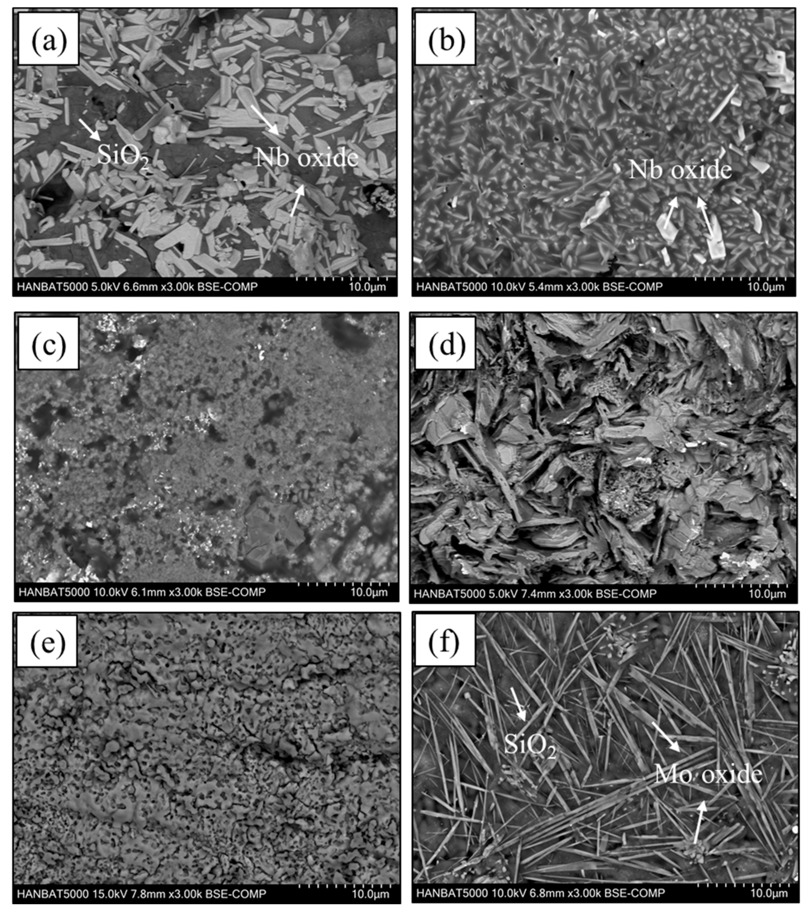
Figure 6 shows SEM BSE images of the surface of the Si-pack-coated Nb
xMo
y alloys after the oxidation tests at 1200 °C for 6 h. Regarding the pure Nb and pure Mo substrates,
Figure 6a,f show SEM BSE images of the surface of the coated Alloy 1 (Nb) and Alloy 6 (Mo) after the oxidation tests, respectively. The phase sequence was identified as SiO
2+Nb oxide for the coated Alloy 1 (Nb) and SiO
2+Mo oxide for the coated Alloy 6 (Mo), respectively.
Figure 6b–e show SEM BSE images of the surface of the coated Alloy 2 (Nb
73.6Mo
26.4), Alloy 3 (Nb
51.2Mo
48.8), Alloy 4 (Nb
35.1Mo
64.9), and Alloy 5 (Nb
25.7Mo
74.3) after the oxidation tests. Different from
Figure 6a,f, mixed oxides of SiO
2 and Nb
2O
5 with some Mo content were produced at the surface for the alloys of Alloy 2 (Nb
73.6Mo
26.4), Alloy 3 (Nb
51.2Mo
48.8), Alloy 4 (Nb
35.1Mo
64.9), and Alloy 5 (Nb
25.7Mo
74.3) as shown
Figure 6b–e.
Figure 7 shows SEM BSE images of a cross section of the Si-pack-coated Nb
xMo
y alloys after the oxidation tests at 1200 °C for 6 h.
Figure 7a,f show SEM BSE images of cross sections of the coated Alloy 1 (Nb) and Alloy 6 (Mo) after oxidation tests, consisting of several layers. The phase sequence was identified as SiO
2 + Nb
2O
5/NbSi
2/Nb
5Si
3/Nb for the coated Alloy 1 (Nb) and SiO
2/MoSi
2/Mo
5Si
3/Mo for the coated Alloy 6 (Mo). In the case of the coated Alloy 1 (Nb), a Nb
5Si
3 phase was also formed as a layer with a thickness of about 10 µm between the NbSi
2 layer and the substrate. Similarly, the Mo
5Si
3 layer in the coated Alloy 6(Mo) was also formed with a thickness of about 17 µm between the MoSi
2 layer and the substrate.
Figure 7b–e show SEM BSE images of cross sections of the coated Alloy 2 (Nb
73.6Mo
26.4), Alloy 3 (Nb
51.2Mo
48.8), Alloy 4 (Nb
35.1Mo
64.9), and Alloy 5 (Nb
25.7Mo
74.3) after the oxidation tests. Generally, the layer sequence was observed as an oxide layer/(Nb, Mo)Si
2/(Nb, Mo)
5Si
3/substrate after the oxidation tests; the (Nb
x, Mo
y)
5Si
3 layer was thicker than before the oxidation tests. In
Figure 7a–c, some surface pores were found in the SiO
2 oxide layer, indicating that the surface oxide was unprotected. However, Alloy 4 (Nb
35.1Mo
64.9), which has a higher Mo content than Alloy 3 (Nb
51.2Mo
48.8), was well protected by a SiO
2 protective layer, indicating that the outer coating layer composition originating from substrates is a critical factor for the protection of the substrate.
In order to examine the surface oxides after the oxidation tests, XRD was carried out for all of the coated alloys.
Figure 8 shows the XRD patterns of the Si-pack-coated specimens after oxidation tests at 1200 °C for 6 h. As shown in
Figure 8a, SiO
2 and Nb
2O
5 phases were observed when the content of Nb was increased in the Nb–Mo alloys.
The weight changes after the oxidation tests with and without coatings are shown in
Figure 9. When the specimens were not coated, about a 50 % specific weight change was observed after oxidation. However, the coated specimens did not show any abrupt weight changes after oxidation for any of the alloys, as shown in
Figure 9. It should be noted that for Alloy 1 (Nb), Alloy 2 (Nb
73.6Mo
26.4), and Alloy 3 (Nb
51.2Mo
48.8), the oxides were composed of mainly SiO
2 + Nb
2O
5. When the substrate was alloys of Alloy 4 (Nb
35.1Mo
64.9), Alloy 5 (Nb
25.7Mo
74.3), and Alloy 6 (Mo), the surface oxides were mainly SiO
2 with some Mo oxides. As shown in
Figure 5, after oxidation, the surface roughness increased for the coated pure Nb and Nb-rich alloys, indicating that specific weight changes do not directly indicate the soundness of the alloys. Regarding this relationship, the oxidation of the coated surface (Nb
x, Mo
y)Si
2 layers often undergoes a weight increase due to oxide formation at the surface, together with a weight reduction due to sublimation and/or pore formation, which affects weight changes after oxidation. Further investigation will be reported in order to identify structural evolution upon long-term exposure to high temperatures.
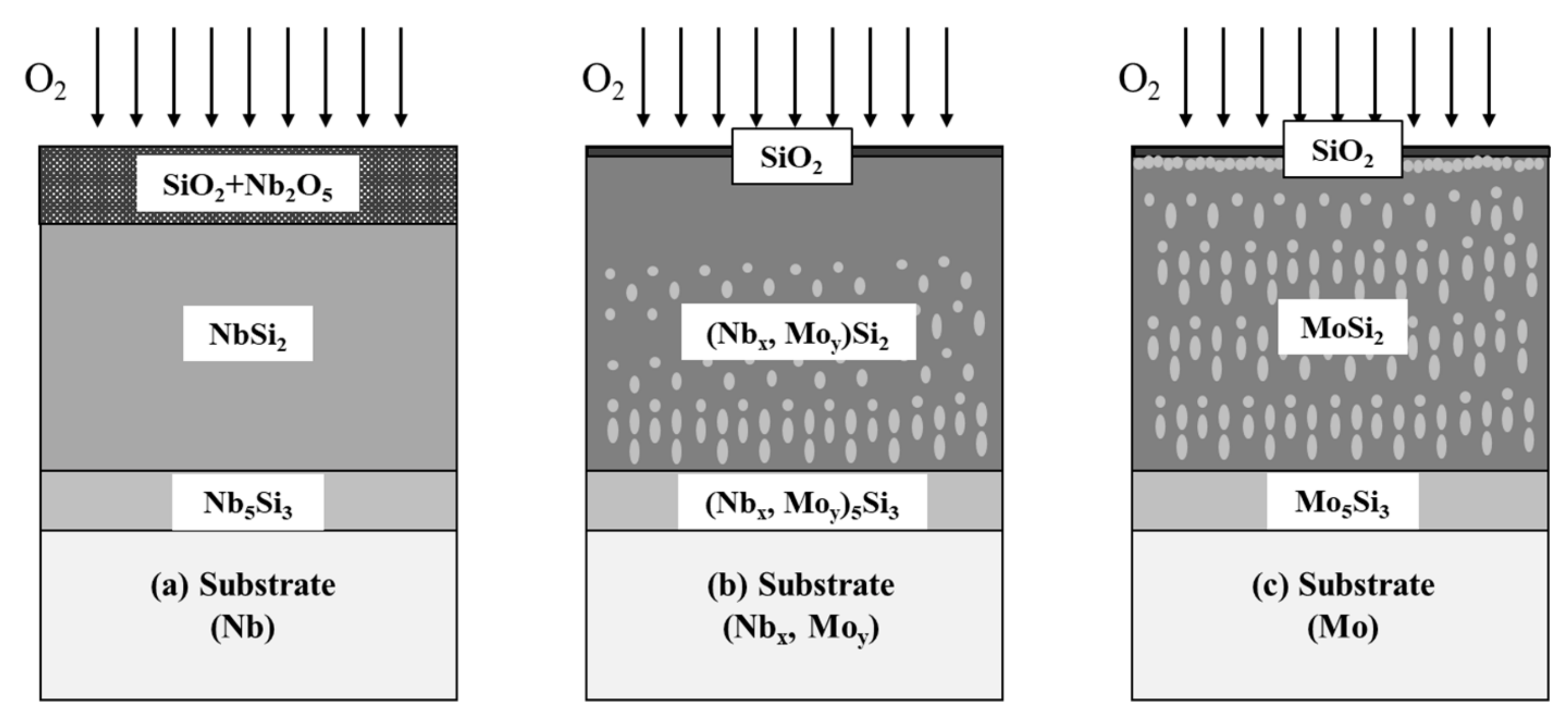
Figure 10 is a schematic illustration of the oxidation behavior of the coated Nb
xMo
y alloys at 1200 °C. For Alloy 1 (Nb), Alloy 2 (Nb
73.6Mo
26.4), and Alloy 3 (Nb
51.2Mo
48.8), a thick layer of SiO
2+Nb
2O
5 formed on the surface, resulting from the oxidation of NbSi
2. Nb
2O
5 is well known as a non-protective layer. The oxide produces pores when it forms at high temperatures, resulting in the severe damage that was observed for the Nb-based alloys (
Figure 10a).
Figure 10b is a schematic diagram showing the oxidation behavior of coated Alloy 4 (Nb
35.1Mo
64.9) and Alloy 5 (Nb
25.7Mo
74.3) after oxidation tests. Since the Nb content is relatively low, the Si in the (Nb, Mo)Si
2 layer reacted during oxidation to form a SiO
2 oxide layer on the surface to suppress further oxidation. When the alloy is exposed to air at high temperatures, the produced (Nb, Mo)Si
2 and (Nb, Mo)
5Si
3 coating layer protects the substrate.
Figure 10c is a schematic diagram showing the oxidation behavior of the coated Mo alloy after oxidation tests. A thin layer of SiO
2 oxide formed on the surface, where the MoSi
2 and Mo
5Si
3 phases formed. In addition, as Si diffuses outward, the thickness of Mo
5Si
3 phase increases.
It has been documented that Nb alloys usually do not have oxidation resistance at 1200 °C due to the formation of porous oxide phases of SiO2 + Nb2O5. Severe oxidation behavior occurs when the substrate is even coated with NbSi2. However, the present results show that when a certain amount of Mo is present in the NbSi2 layer, the surface (Nb, Mo)Si2 layer protects the substrate. While further investigation and phase analyses are needed, the present study clearly shows that an appropriate amount of Mo and Nb in the NbxMoy substrates can protected the Si-pack-coated substrate at high-temperature exposure under an ambient atmosphere.


