Characterization of Ceramics Coatings Processed by Sol-Gel for Cutting Tools

 , , , ,
  and
and
Abstract
:1. Introduction
2. Materials and Methods
2.1. Workpiece and Cutting Tools
2.2. Cleaning of the Cutting Tools
2.3. TiO2 Coating
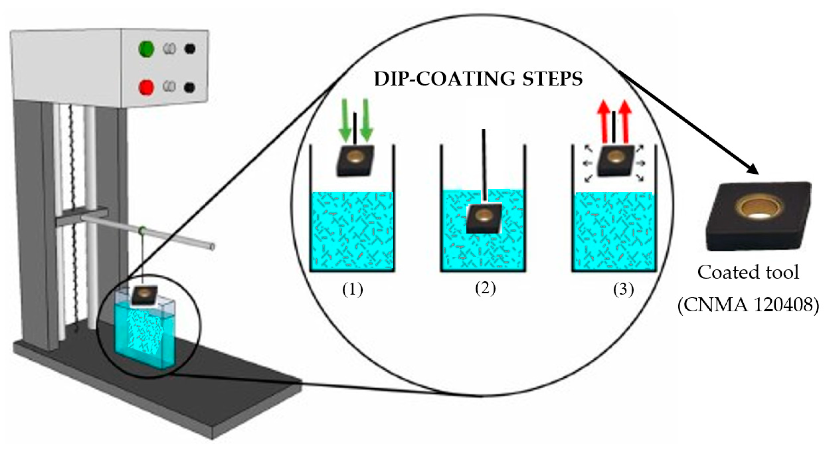
2.4. Al2O3 Coating
2.5. Characterization of the Coatings
2.6. Scratch Test
2.7. Tribometer Test
2.8. Cutting Force
2.9. Experimental Setup
3. Results and Discussions
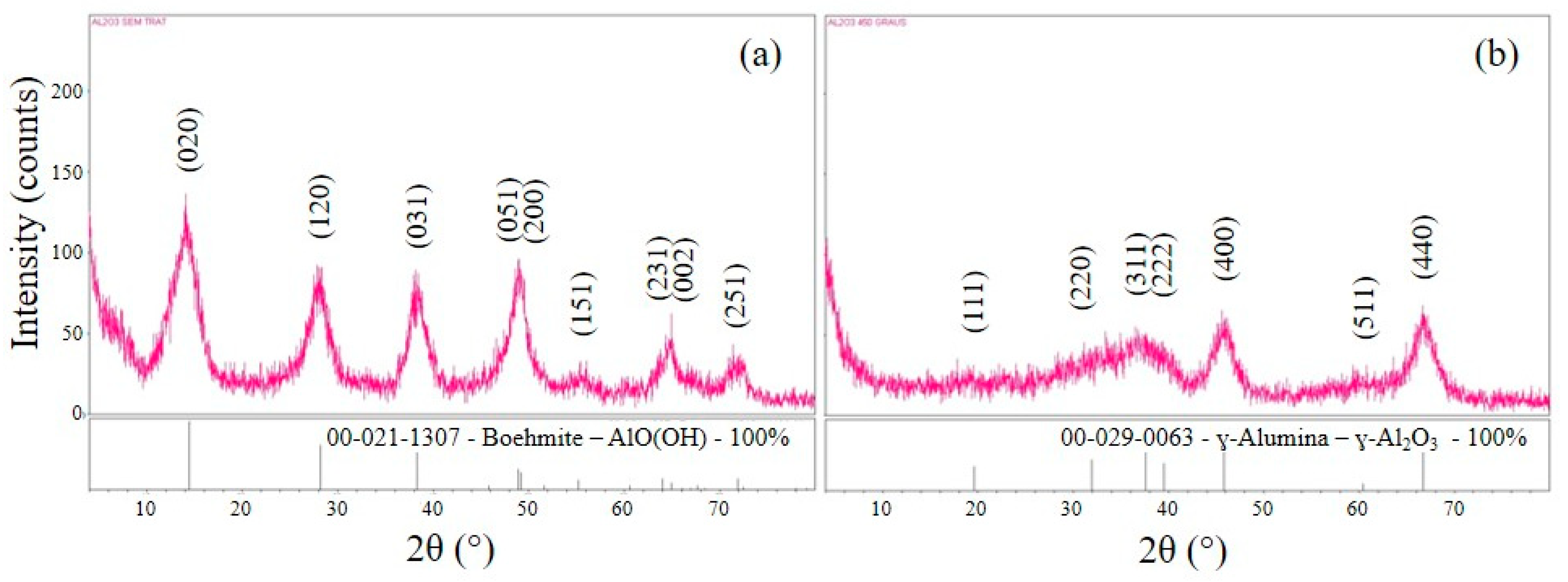
3.1. X-ray Diffraction
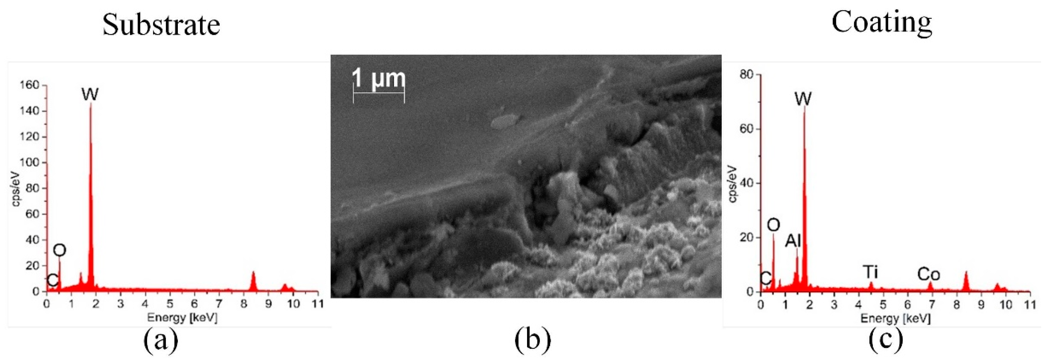
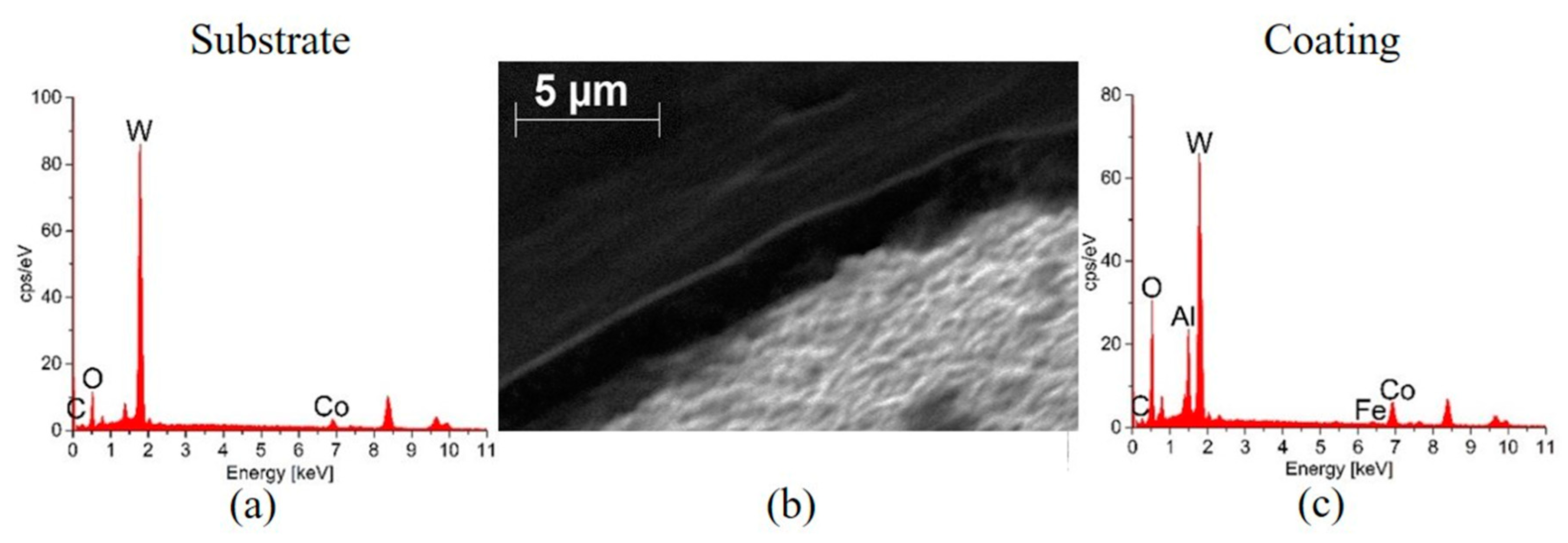
3.2. Characterization of Aluminium Oxide Coating
3.3. Characterization of Titanium Dioxide Coating
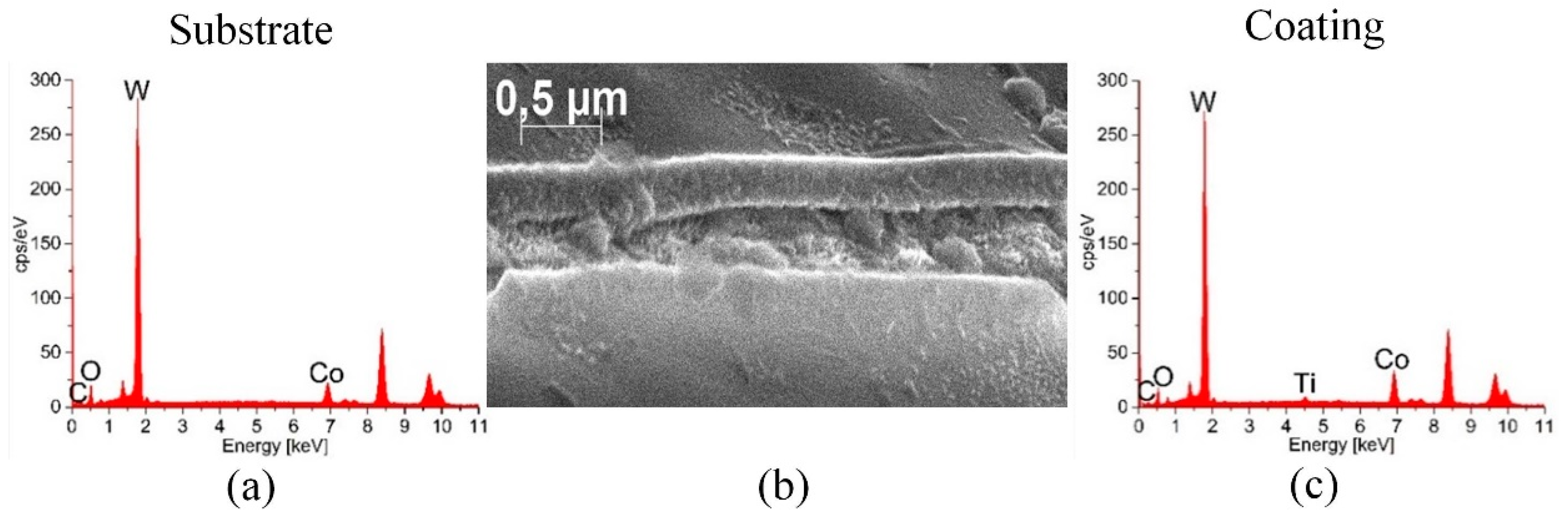
3.4. Characterization of Multilayer Coating
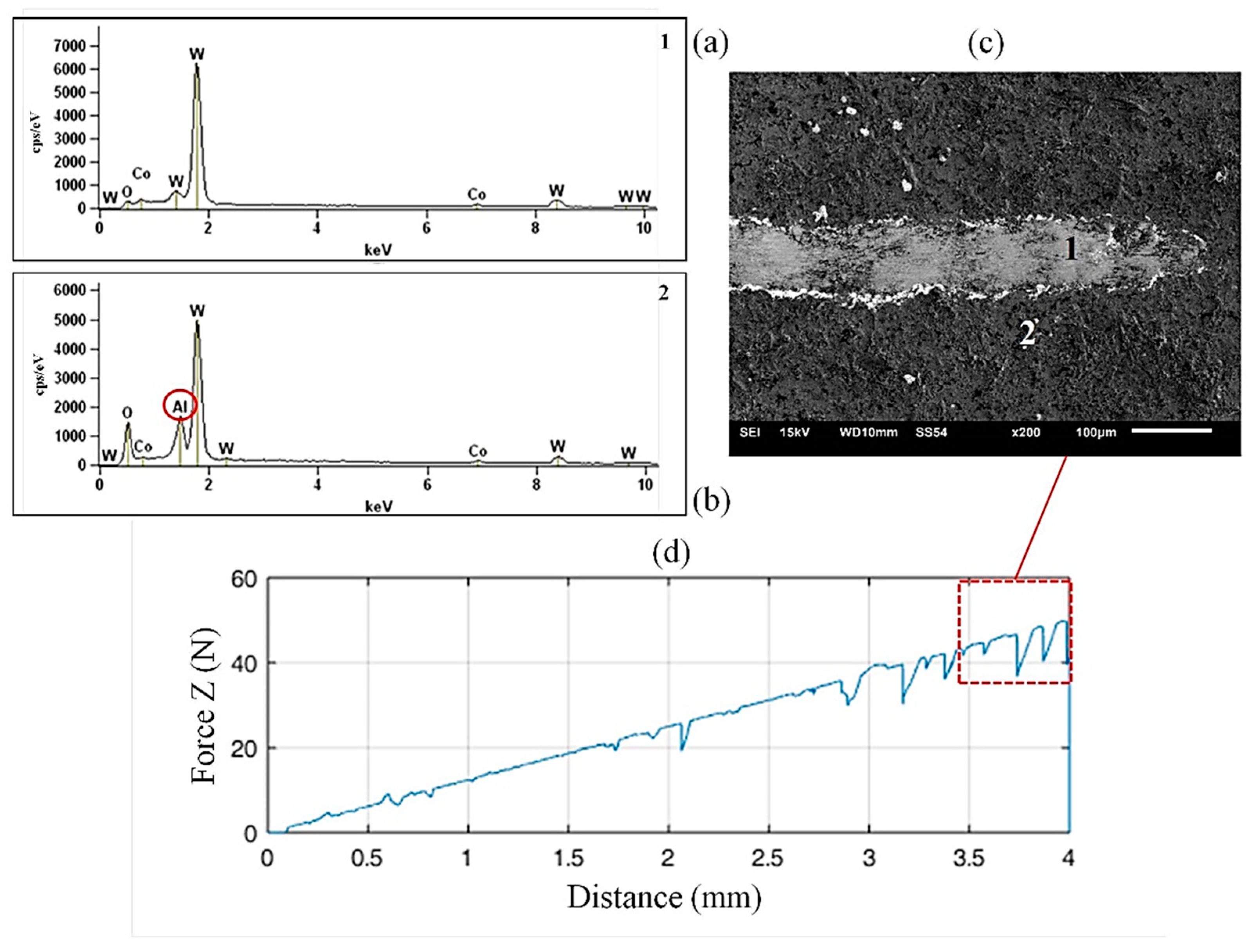
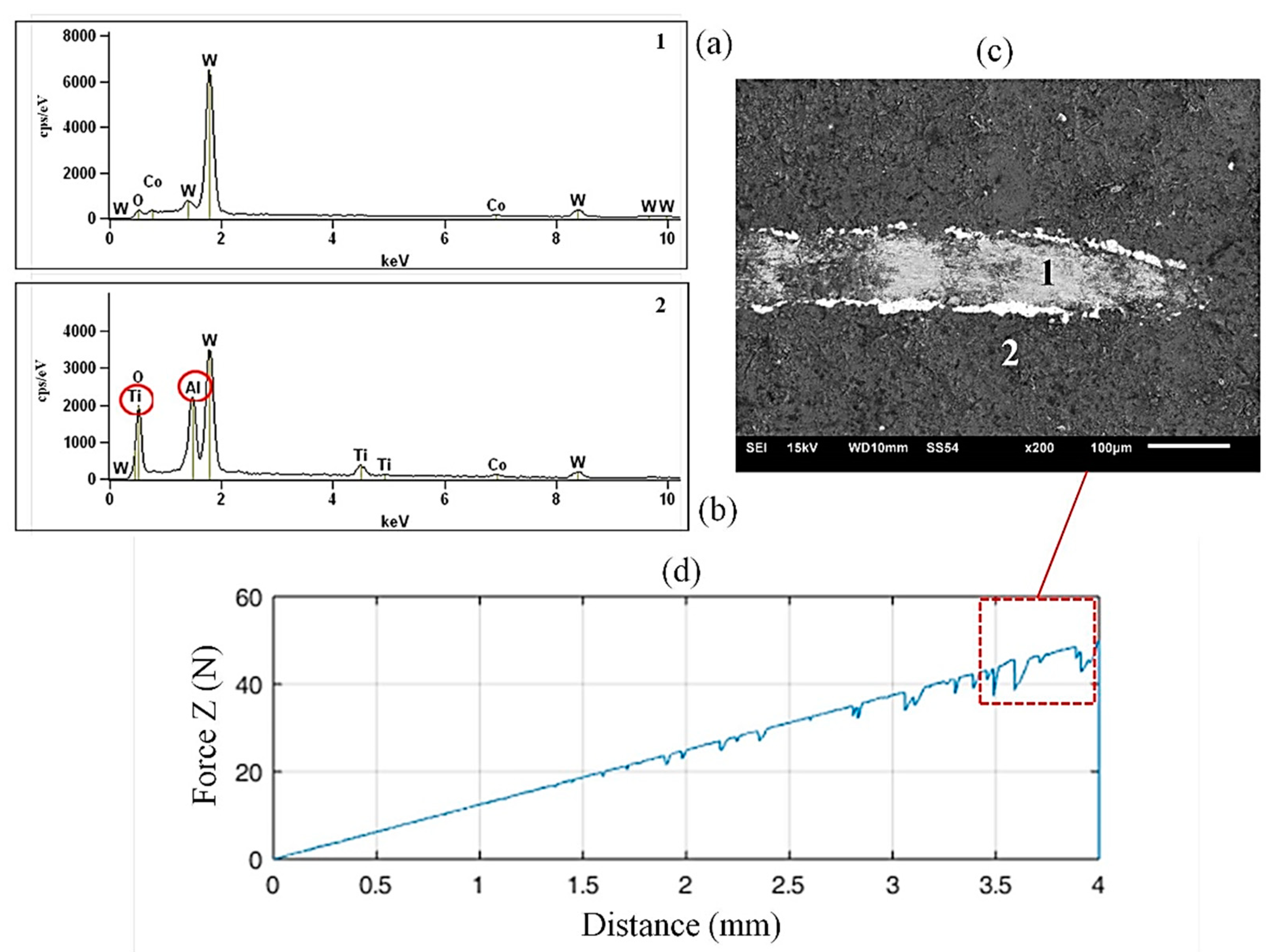
3.5. Adhesion by Scratch Test
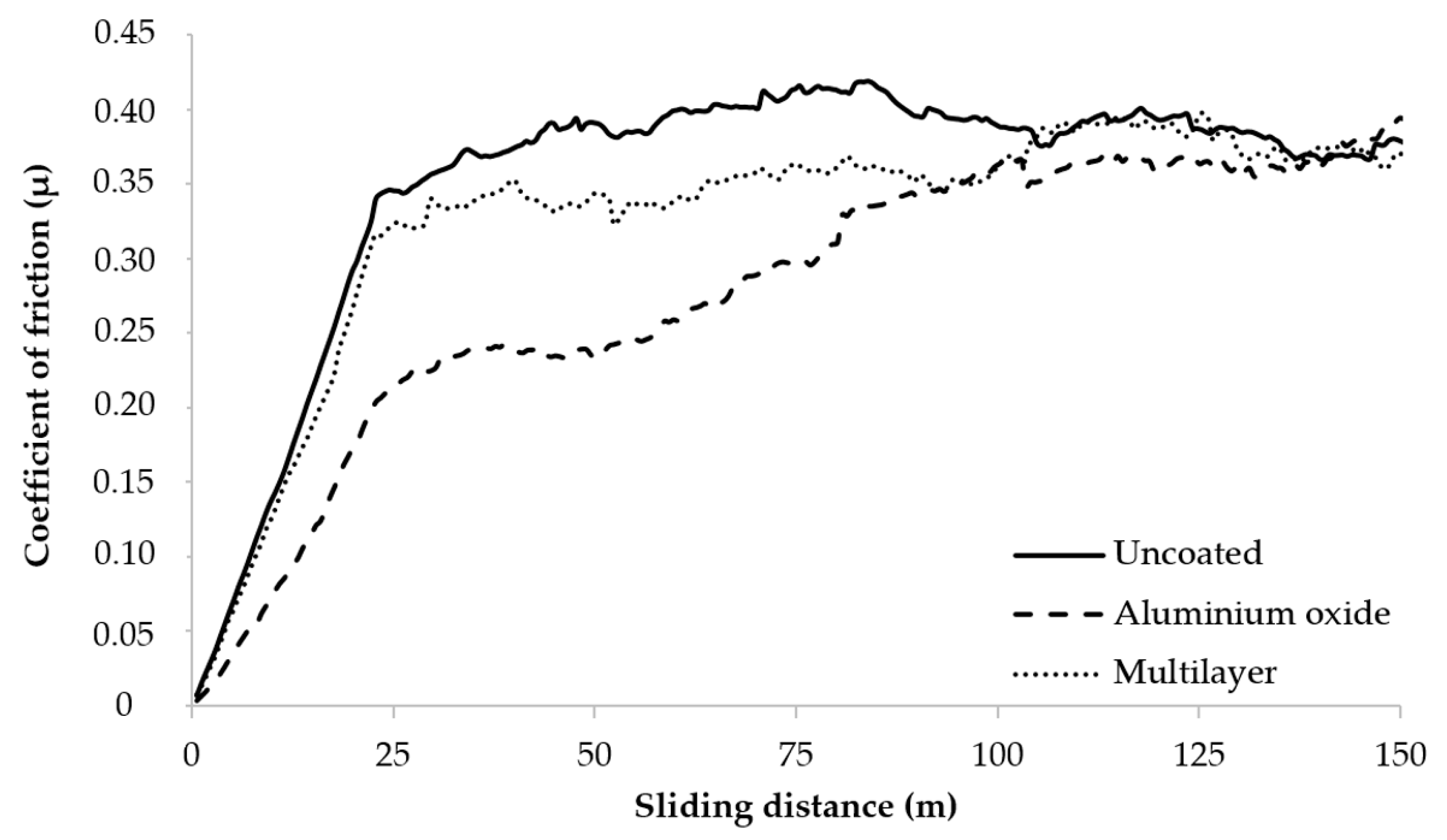
3.6. Coefficient of Friction (µ)
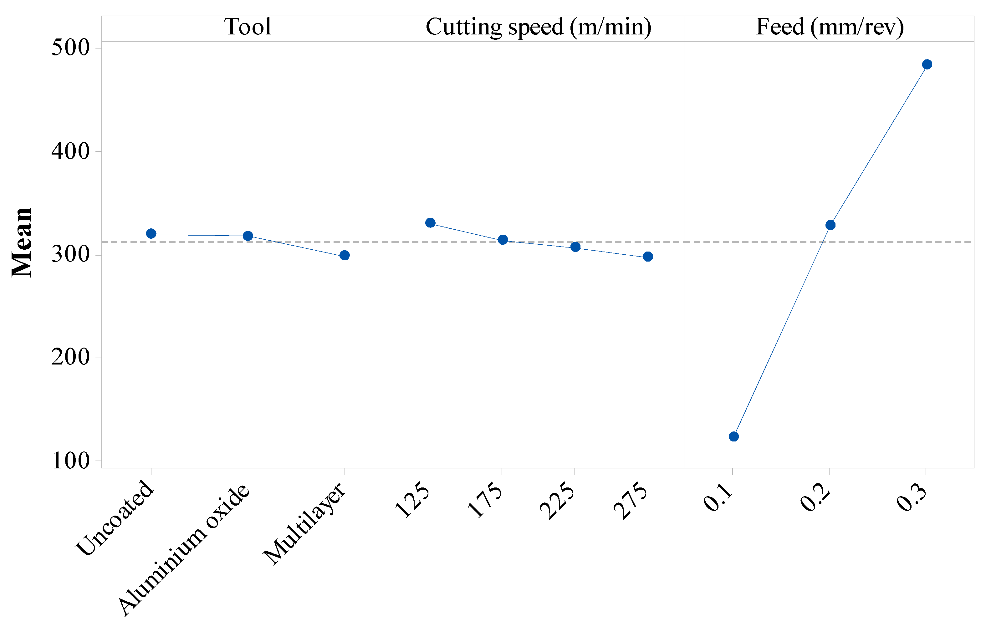
3.7. Cutting Force
4. Conclusions
- According to XRD analyses, the alumina coating deposited on the tool surfaces presented a crystalline structure corresponding to the ɣ-Al2O3 phase after the heat treatment step.
- The EDS confirmed the presence of the coatings and the thicknesses of the coatings have a micrometer scale (Al2O3 and multilayer).
- According to the scratch test, the adhesion of the multilayer coating is higher than the one of the Al2O3 coating.
- The coated tools presented lower friction coefficients up to 100 m. Besides, during the CGI cutting tests, the presence of graphite probably contributed to the reduction of friction due to the formation of a lubricating film.
- The ANOVA showed that the main parameter that influenced the resulting cutting force was the feed. The tool and cutting speed have minor influences.
Author Contributions
Funding
Conflicts of Interest
References
- Gouveia, R.M.; Silva, F.J.G.; Reis, P.; Baptista, A.P.M. Machining duplex stainless steel: comparative study regarding end mill coated tools. Coatings 2016, 6, 51. [Google Scholar] [CrossRef]
- Tooptong, S.; Park, K.-H.; Kwon, P. A comparative investigation on flank wear when turning three cast irons. Tribol. Int. 2018, 120, 127–139. [Google Scholar] [CrossRef]
- Stylianou, R.; Tkadletz, M.; Schalk, N.; Penoy, M.; Czettl, C.; Mitterer, C. Effects of reference materials on texture coefficients determined for a CVD α-Al2O3 coating. Surf. Coat. Technol. 2019, 359, 314–322. [Google Scholar] [CrossRef]
- Pulci, G.; Tirillò, J.; Marra, F.; Sarasini, F.; Bellucci, A.; Valente, T.; Bartuli, C. High temperature oxidation of MCrAlY coatings modified by Al2O3 PVD overlay. Surf. Coat. Technol. 2015, 268, 198–204. [Google Scholar] [CrossRef]
- Yang, K.; Chen, J.; Hao, F.; Liu, C.; Tao, S.; Ding, C. Stress-induced phase transformation and amorphous-to-nanocrystalline transition in plasma-sprayed Al2O3 coating with relative low temperature heat treatment. Surf. Coat. Technol. 2014, 253, 277–283. [Google Scholar] [CrossRef]
- Chen, Y.-C.; Ai, X.; Huang, C.-Z.; Wang, B.-Y. Preparation of α-alumina coated carbide tools by the sol-gel process. Mater. Sci. Eng. A 2000, 288, 19–25. [Google Scholar] [CrossRef]
- Pereira, N.; Rubio, J.C.C.; Santos, A.J.; Houmard, M.; Câmara, M.A.; Rodrigues, A.R. Drilling of nodular cast iron with a novel SiO2 coating deposited by sol-gel process in HSS drill. Int. J. Adv. Manuf. Technol. 2019, in press. [Google Scholar] [CrossRef]
- Astakhov, V.P. Tribology of Metal Cutting, 1st ed.; Elsevier: Oxford, UK, 2006. [Google Scholar]
- Rubio, J.C.C.; Rezende, B.A.; Vieira, L.M.G.; Romero, H.M.; Brenes, L.A.R. Comparative study on lubricating and cooling conditions in the drilling process of electrolytic copper. Int. J. Adv. Manuf. Technol. 2019, 101, 2633–2641. [Google Scholar] [CrossRef]
- Rao, J.; Sharma, A.; Rose, T. Titanium aluminium nitride and titanium boride multilayer coatings designed to combat tool wear. Coatings 2018, 8, 12. [Google Scholar] [CrossRef]
- Dobrzański, L.A.; Skrzypek, S.; Pakuła, D.; Mikuła, J.; Křiž, A. Influence of the PVD and CVD technologies on the residual macro-stresses and functional properties of the coated tool ceramics. J. Achiev. Mater. Manuf. Eng. 2009, 35, 162–168. [Google Scholar]
- Rubio, J.C.C.; Rezende, B.A.; Vieira, L.M.G.; Houmard, M. Drilling of aluminium/PE sandwich material with a novel TiO2-coated HSS drill deposited by sol-gel process. Int. J. Adv. Manuf. Technol. 2017, 92, 1567–1577. [Google Scholar]
- Tlili, B.; Barkaoui, A.; Walock, M. Tribology and wear resistance of the stainless steel. The sol–gel coating impact on the friction and damage. Tribol. Int. 2016, 102, 348–354. [Google Scholar] [CrossRef]
- Wright, J.D.; Sommerdijk, N.A.J.M. Sol-Gel Materials: Chemistry and Applications, 1st ed.; Gordon and Breach Science Publishers: Amsterdam, The Netherlands, 2001. [Google Scholar]
- Dai, W.X.; Chen, X.; Li, E.; Wang, X.X.; Liu, P.; Fu, X.Z. Influence of pH value of TiO2 sol on surface gloss of corresponding TiO2 film coated on ceramic tiles. Surf. Eng. 2009, 25, 106–110. [Google Scholar] [CrossRef]
- Brinker, C.J.; Scherer, G.W. Sol-Gel Science: The Physics and Chemistry of Sol-Gel Processing; Academic Press: Boston, MA, USA, 1990. [Google Scholar]
- Yang, S.; Zhang, Y.; Mo, D. Spectroscopic ellipsometry studies of sol-gel-derived Cu-doped ZnO thin films. Thin Solid Films 2014, 571, 605–608. [Google Scholar] [CrossRef]
- Schneller, T.; Waser, R.; Kosec, M.; Payne, D. Chemical Solution Deposition of Functional Oxide Thin Films; Springer: Wien, Austria, 2013. [Google Scholar]
- Czettl, C.; Pohler, M. Progress in development of coated indexable cemented carbide inserts for machining of iron based work piece materials. IOP Conf. Ser. Mater. Sci. Eng. 2016, 119, 012011. [Google Scholar] [CrossRef]
- Toma, F.L.; Stahr, C.C.; Berger, L.M.; Saaro, S.; Herrmann, M.; Deska, D.; Michael, G. Corrosion resistance of APS- and HVOF-sprayed coatings in the Al2O3-TiO2 system. J. Therm. Spray Technol. 2010, 19, 137–147. [Google Scholar] [CrossRef]
- Gurylev, V.; Su, C.-Y.; Perng, T.-P. Surface reconstruction, oxygen vacancy distribution and photocatalytic activity of hydrogenated titanium oxide thin film. J. Catal. 2015, 330, 177–186. [Google Scholar] [CrossRef]
- Du, X.; Men, K.; Xu, Y.; Li, B.; Yang, Z.; Liu, Z.; Li, L.; Li, L.; Feng, T.; Rehman, W.U.; et al. Enhanced capacitance performance of Al2O3–TiO2 composite thin film via sol-gel using double chelators. J. Colloid Interface Sci. 2015, 443, 170–176. [Google Scholar] [CrossRef]
- Su, G.; Guo, Y.; Song, X.; Tao, H. Effects of high-pressure cutting fluid with different jetting paths on tool wear in cutting compacted graphite iron. Tribol. Int. 2016, 103, 289–297. [Google Scholar] [CrossRef]
- Abdoos, M.; Yamamoto, K.; Bose, B.; Fox-Rabinovich, G.; Veldhuis, S. Effect of coating thickness on the tool wear performance of low stress TiAlN PVD coating during turning of compacted graphite iron (CGI). Wear 2019, 422–423, 128–136. [Google Scholar] [CrossRef]
- Yamamoto, K.; Abdoos, M.; Paiva, J.M.; Stolf, P.; Beake, B.; Rawal, S.; Fox-Rabinovich, G.; Veldhuis, S. Cutting performance of low stress thick TiAlN PVD coatings during machining of compacted graphite cast iron (CGI). Coatings 2018, 8, 38. [Google Scholar] [CrossRef]
- Heep, T.; Bickert, C.; Abele, E. Application of carbon dioxide snow in machining of CGI using an additively manufactured turning tool. J. Manuf. Mater. Process. 2019, 3, 15. [Google Scholar] [CrossRef]
- ASTM A842-85 (2009). Standard Specification for Compacted Graphite Iron Castings; ASTM International: West Conshohocken, PA, USA, 2009. [Google Scholar]
- Houmard, M.; Vasconcelos, D.C.L.; Vasconcelos, W.L.; Berthomé, G.; Joud, J.C.; Langlet, M. Water and oil wettability of hybrid organic-inorganic titanate-silicate thin films deposited via a sol-gel route. Surf. Sci. 2009, 603, 2698–2707. [Google Scholar] [CrossRef]
- ASTM G99-05 (2010). Standard Test Method for Wear Testing with a Pin-on-Disk Apparatus; American Society for Testing and Materials: Philadelphia, PA, USA, 2010. [Google Scholar]
- Langlet, M.; Permpoon, S.; Riassetto, D.; Berthomé, G.; Pernot, E.; Joud, J. Photocatalytic activity and photo-induced superhydrophilicity of sol-gel derived TiO2 films. J. Photochem. Photobiol. A Chem. 2006, 181, 203–214. [Google Scholar] [CrossRef]
- Aun, D.P.; Houmard, M.; Mermoux, M.; Latu-Romain, L.; Joud, J.; Berthomé, G.; Buono, V.T.L. Development of a flexible nanocomposite TiO2 film as a protective coating for bioapplications of superelastic NiTi alloys. Appl. Surf. Sci. 2016, 375, 42–49. [Google Scholar] [CrossRef]
- Kalpakjian, S.; Schimd, S.R. Manufacturing Engineering and Technology, 6th ed.; Prentice Hall: Upper Saddle River, NJ, USA, 2010. [Google Scholar]
- Trent, E.M.; Wright, P.K. Metal Cutting, 4th ed.; Butterworth Heinemann: Woburn, MA, USA, 2000. [Google Scholar]
- Puls, H.; Klocke, F.; Lung, D. Experimental investigation on friction under metal cutting conditions. Wear 2014, 310, 63–71. [Google Scholar] [CrossRef]


| Properties | Grade 350 |
|---|---|
| Tensile strength limit (MPa) | 350 |
| Flow limit (MPa) | 245 |
| Elongation 50 mm (%) | 1.0 |
| Parameters | Levels |
|---|---|
| Tool | Uncoated; Al2O3 coated tool; Multilayer coated tool |
| Cutting speed (Vc) | 125; 175; 225; 275 m/min |
| Feed (f) | 0.1; 0.2; 0.3 mm/rev |
| Test | Tool | Vc | f | Cutting Force (N) | Test | Tool | Vc | f | Cutting Force (N) | ||
|---|---|---|---|---|---|---|---|---|---|---|---|
| 1 | 1 | 1 | 1 | 126.50 | 140.95 | 19 | 2 | 3 | 1 | 108.22 | 134.21 |
| 2 | 1 | 1 | 2 | 353.48 | 352.81 | 20 | 2 | 3 | 2 | 333.94 | 322.76 |
| 3 | 1 | 1 | 3 | 499.69 | 474.54 | 21 | 2 | 3 | 3 | 487.27 | 485.39 |
| 4 | 1 | 2 | 1 | 109.09 | 165.36 | 22 | 2 | 4 | 1 | 121.13 | 95.91 |
| 5 | 1 | 2 | 2 | 347.27 | 336.46 | 23 | 2 | 4 | 2 | 322.25 | 308.87 |
| 6 | 1 | 2 | 3 | 484.86 | 508.22 | 24 | 2 | 4 | 3 | 511.39 | 452.57 |
| 7 | 1 | 3 | 1 | 145.95 | 96.60 | 25 | 3 | 1 | 1 | 157.30 | 126.73 |
| 8 | 1 | 3 | 2 | 372.18 | 302.98 | 26 | 3 | 1 | 2 | 360.82 | 336.75 |
| 9 | 1 | 3 | 3 | 498.97 | 492.68 | 27 | 3 | 1 | 3 | 502.31 | 482.00 |
| 10 | 1 | 4 | 1 | 118.15 | 103.74 | 28 | 3 | 2 | 1 | 109.44 | 129.72 |
| 11 | 1 | 4 | 2 | 338.06 | 326.79 | 29 | 3 | 2 | 2 | 276.90 | 320.82 |
| 12 | 1 | 4 | 3 | 493.43 | 478.78 | 30 | 3 | 2 | 3 | 451.72 | 492.45 |
| 13 | 2 | 1 | 1 | 135.46 | 152.02 | 31 | 3 | 3 | 1 | 89.12 | 140.17 |
| 14 | 2 | 1 | 2 | 404.81 | 331.30 | 32 | 3 | 3 | 2 | 288.53 | 299.60 |
| 15 | 2 | 1 | 3 | 520.92 | 481.44 | 33 | 3 | 3 | 3 | 458.90 | 457.99 |
| 16 | 2 | 2 | 1 | 112.45 | 149.95 | 34 | 3 | 4 | 1 | 86.34 | 110.46 |
| 17 | 2 | 2 | 2 | 341.43 | 327.68 | 35 | 3 | 4 | 2 | 263.44 | 314.25 |
| 18 | 2 | 2 | 3 | 491.98 | 487.77 | 36 | 3 | 4 | 3 | 437.74 | 471.13 |
| Process Parameters | Cutting Force | ||
|---|---|---|---|
| SS | F-Value | p-Value | |
| Tool | 6436 | 5.89 | 0.006 |
| Cutting speed | 10,229 | 6.24 | 0.002 |
| Feed | 1,564,893 | 1431.83 | 0.000 |
| Tool × Cutting speed | 2346 | 0.72 | 0.640 |
| Tool × feed | 1600 | 0.73 | 0.576 |
| Cutting speed × Feed | 1610 | 0.49 | 0.811 |
| Tool × Cutting speed × Feed | 388 | 0.06 | 1.000 |
| R2 | 98.78% | – | – |
© 2019 by the authors. Licensee MDPI, Basel, Switzerland. This article is an open access article distributed under the terms and conditions of the Creative Commons Attribution (CC BY) license (http://creativecommons.org/licenses/by/4.0/).
Share and Cite
Rezende, B.A.; dos Santos, A.J.; Câmara, M.A.; do Carmo, D.J.; Houmard, M.; Rodrigues, A.R.; Campos Rubio, J.C. Characterization of Ceramics Coatings Processed by Sol-Gel for Cutting Tools. Coatings 2019, 9, 755. https://doi.org/10.3390/coatings9110755
Rezende BA, dos Santos AJ, Câmara MA, do Carmo DJ, Houmard M, Rodrigues AR, Campos Rubio JC. Characterization of Ceramics Coatings Processed by Sol-Gel for Cutting Tools. Coatings. 2019; 9(11):755. https://doi.org/10.3390/coatings9110755
Chicago/Turabian StyleRezende, Bruna Aparecida, Anderson Júnior dos Santos, Marcelo Araújo Câmara, Denilson José do Carmo, Manuel Houmard, Alessandro Roger Rodrigues, and Juan Carlos Campos Rubio. 2019. "Characterization of Ceramics Coatings Processed by Sol-Gel for Cutting Tools" Coatings 9, no. 11: 755. https://doi.org/10.3390/coatings9110755
APA StyleRezende, B. A., dos Santos, A. J., Câmara, M. A., do Carmo, D. J., Houmard, M., Rodrigues, A. R., & Campos Rubio, J. C. (2019). Characterization of Ceramics Coatings Processed by Sol-Gel for Cutting Tools. Coatings, 9(11), 755. https://doi.org/10.3390/coatings9110755