1. Introduction
The solid oxide fuel cell (SOFC) is a new type of green power generation device that can directly convert the chemical energy of fuels into electric energy at high efficiency [
1]. A current research hotspot is to develop SOFCs capable of operating at low temperature (≤600 °C), aiming to reduce the cost and extend the battery life [
2]. However, lowering the operating temperature will increase the electrolyte resistance leading to a significant decrease in battery performance. A proposed solution is to develop a dense electrolyte coating with high electrical conductivity at low temperatures. Gadolinia-doped ceria (GDC) is one of the most promising candidates, as its ion conductivity at 600 °C reaches 0.01–0.02 S/cm [
3]. The conventional preparation method for the GDC electrolyte is sintering, but this makes it difficult to rapidly prepare dense GDC electrolyte on a large area without cracks.
As an alternative method, the low-pressure plasma spray (LPPS) process is promising, with significant advantages, as the high-power plasma jet at low pressure can completely melt the electrolyte material and accelerate it to 2–3 times the speed of sound, which is beneficial to increase the density of the coating. In addition, the deposition efficiency is much higher than traditional vapor deposition processes, enabling rapid and uniform preparation on a large area [
4,
5,
6,
7,
8,
9,
10]. By adopting different plasma torches and powers, the LPPS can be divided into the very-low-pressure plasma spray (VLPPS) and plasma spray–physical vapor deposition (PS-PVD). The difference between them is that the VLPPS coating is mainly deposited with the melted particles, and the PS-PVD coating can be made with the mixed vapor and liquid phases or pure vapor phase. Marcano [
11] used PS-PVD to prepare a dense 8YSZ (yttria-stabilized zirconia) electrolyte. The open-circuit voltage and power density of the single cell were 1.033 V and 0.89 W/cm
2 at 800 °C, respectively. Gao [
5] used VLPPS technology to prepare a dense scandia-stabilized zirconia electrolyte (ScSZ). The gas leakage rate was only 1.4 × 10
−7 cm
4 gf
−1 s
−1, and the maximum power density of single cells could reach 0.402 W/cm
2 and 1.164 W/cm
2 at 650 °C and 750 °C, respectively. These studies demonstrated that the electrolytes prepared by the LPPS process are able to meet the operating requirement of SOFCs. However, most researchers used LPPS to prepare medium–high temperature SOFC electrolytes, such as YSZ and ScSZ coatings. Few studies have focused on the preparation of GDC electrolytes for low-temperature solid oxide fuel cells (LT-SOFCs) via LPPS.
In this paper, a specially formulated agglomerated GDC powder, suitable for LPPS, was prepared via a spray drying process. Then the VLPPS and PS-PVD processes were used to prepare the dense GDC coatings. The adoption of different plasma torches, gases, and powers resulted in that GDC coatings exhibited similar dense microstructures. In order to explain this phenomenon, the morphologies and compositions of the two GDC coatings were analyzed. Additionally, the mechanical properties of coatings were measured, as they are essential for the SOFC application, especially for the electrolyte-supported SOFCs [
12]. Finally, a deposition mechanism model was built to demonstrate the formation processes of the dense GDC coatings using VLPPS and PS-PVD.
2. Experimental Procedure
Since the submicron powder was too hard to be radially delivered into the low-pressure plasma jet, Ce
0.8Gd
0.2O
1.9 powder with an average size of 150 nm was self-agglomerated by a spray dryer (MOBILE MINOR, GEA Niro). The suspension preparation process for the spray drying was as follows: Firstly, the GDC powder, deionized water, and dispersant of polyacrylic acid (PAA, DAMAO CHEMICAL REAGENT) were mixed and milled with agate balls for 2 h. After thorough mixing and milling, another binder of polyvinyl pyrrolidone (PVP, DAMAO CHEMICAL REAGENT) was added and continually milled for another 15 h. The resultant GDC suspension was then transformed with a peristaltic pump into a co-current two-fluid nozzle, where it was atomized by compressed air. Finally, the hot air entered the chamber through a ceiling air disperser, evaporated the solution, which resulted in a dried agglomerated GDC powder. The spray drying parameters are listed in
Table 1. For spraying the GDC coating, the vacuum plasma spraying system (ChamPro, Oerlikon Metco) was employed, which was equipped with the F4-VB and O3CP plasma torches. Carbon steel plates were used as the substrates due to their suitable thermal expansion coefficient. Before spraying, all the substrates were sandblasted and preheated to 600 °C using the plasma jet. The substrate temperature was recorded by an infrared thermometer. The other detailed spraying parameters are shown in
Table 2. The VLPPS parameters favored the melting of GDC powder, and the PS-PVD parameters favored its vaporization. We chose these two parameters to obtain GDC coatings deposited in different states, so as to explore which deposition mode is more conducive to the densification of GDC coatings.
For characterization, the particle size of the spray-dried agglomerated powder was measured by a laser particle size analyzer (MASTERSIZER 3000, Malvern, UK). The phase compositions of the powder and coatings are studied using an X-ray diffractometer (Cu Kα radiation; Rigaku, Tokyo, Japan) operating at 40 kV and 100 mA. The coating microstructures and porosities were observed by field-emission scanning electron microscopy (FEI, Hillsboro, OR, USA) and ImageJ software, respectively. The cross-sectional nanoindentations were measured using a nanoindenter (NHT2, Anton-Paar, Graz, Austria) with a diamond Berkovich tip at a maximum load of 10 mN. The loading and unloading rate, holding time, and temperature were 20 mN/min, 10 s, and 25 °C, respectively. The microhardness and elastic modulus were calculated using the Oliver–Pharr method [
13].
3. Results and Discussion
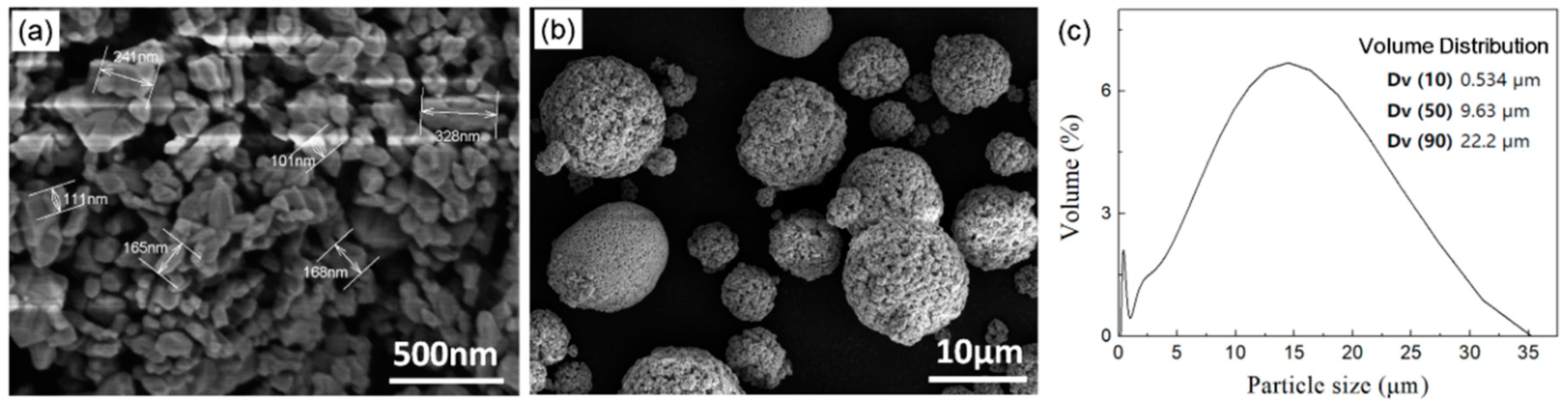
As shown in
Figure 1a, the initial GDC powder had an irregular shape, and the particle size ranged from 100 to 350 nm. After the agglomeration of the spray drying, the sphericity and surface uniformity of the GDC powder were improved (
Figure 1b). Meanwhile, the particle size was increased with volume distributions
D10,
D50, and
D90 of 0.53, 9.63, and 22.2 μm, respectively (
Figure 1c). The relatively small micro-powder could be smoothly fed into the low-pressure plasma jet, and could also be quickly melted or vaporized to obtain a dense GDC coating.
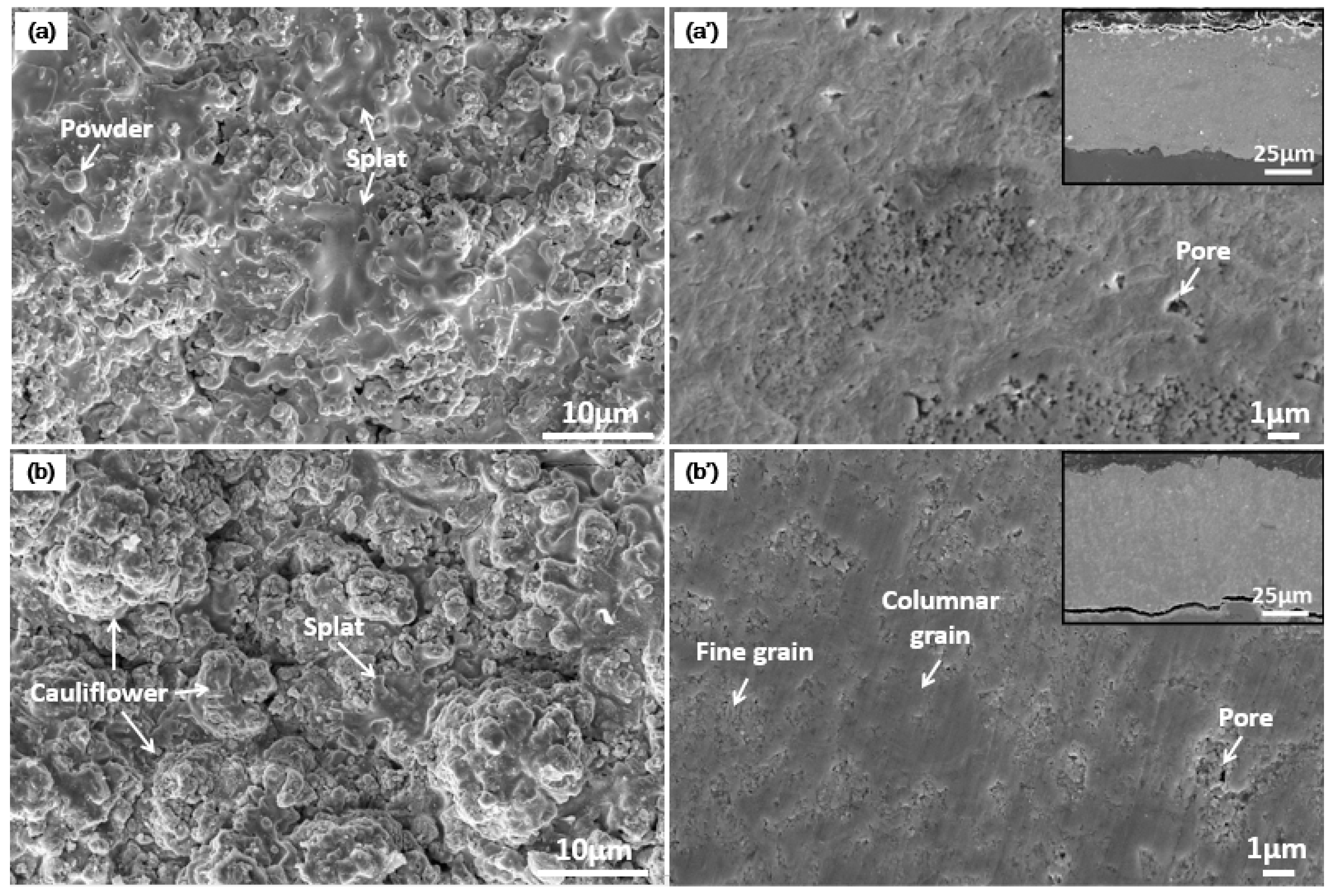
As shown in
Figure 2a, by VLPPS consisted of splats and few unmelted particles. No vapor phase deposition was observed on the surface, indicating that it was a typical liquid deposition. The thickness of the VLPPS coating was about 60 μm (
Figure 2a´), and the microstructure was densely packed with a porosity of 4.28%. No penetrating cracks or holes were noted in the coating, but there were fine pores in some places. The formation of pores and loose structures could be ascribed to the overlapping of the sprayed particles and the volume shrinkage caused by the droplet cooling.
Figure 2b presents a surface image of the GDC coating prepared by the PS-PVD process. As the PV-PVD used much higher plasma power and helium gas, the deposition state of the GDC powder began to change from the liquid phase to the vapor phase. Consequently, a mixed vapor and liquid deposition was formed, and the GDC coating was composed of cauliflower clusters and splats [
14]. This mixed deposition—especially for the cauliflower clusters—would have a shadowing effect on the subsequent deposits. Hence, the PS-PVD coating had a higher surface roughness than the VLPPS coating. Fortunately, the mixed deposition obtained using the PS-PVD process eliminated the unmelted GDC powder that existed in the VLPPS process. Meanwhile, the resulting higher roughness did not create gaps between the adjacent cauliflower clusters. The cross-sectional image (
Figure 2b´) shows that the thickness of the PS-PVD coating was about 80 μm. The microstructure was composed of fine grains, columnar grains, splats, and small pores. The coating porosity was 2.57%, which was denser than the VLPPS coating. No large gaps existed in the coating, and the columnar grains were surrounded by the fine grains and splats.
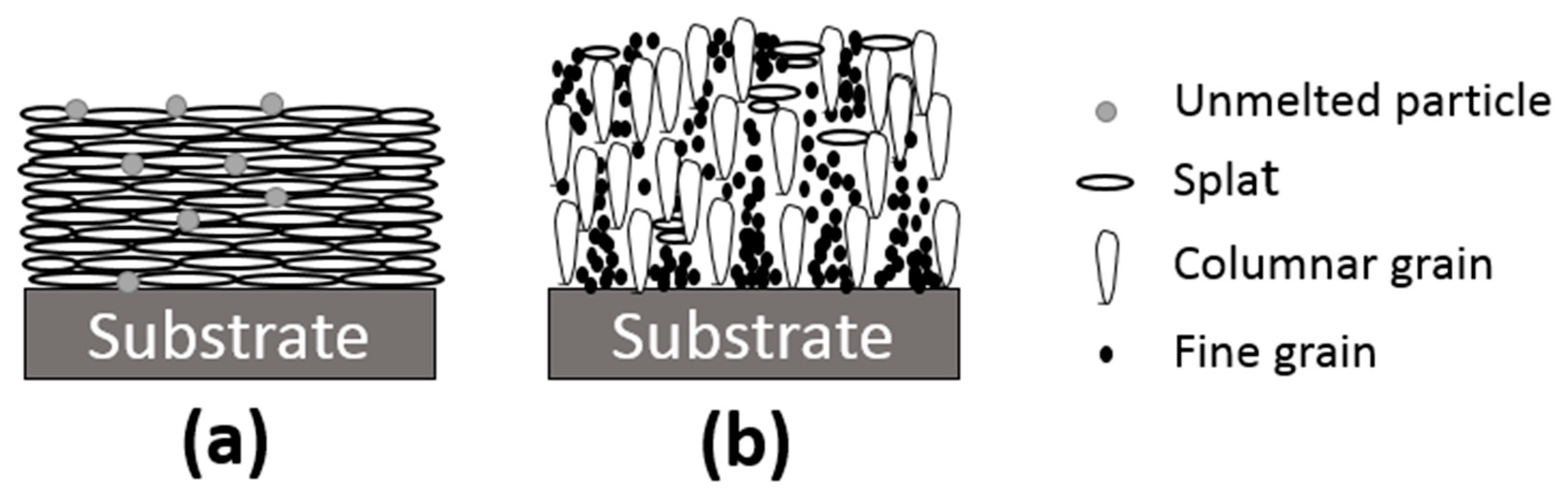
In order to better explain the above phenomenon, the corresponding deposition mechanisms for the VLPPS and PS-PVD are summarized in
Figure 3. On the one hand, the VLPPS coating had a typical lamellar structure with some pores between splats, which could decrease the density of the coating. However, when the powder was injected into the plasma jet, it underwent an accelerating and heating process. As the temperature of the plasma jet was higher than the melting temperature of GDC and the chamber pressure was very low, most of the powder could be fully melted and accelerated with very fast speed [
15]. Once these melted particles landed on the substrate, a typical lamellar structure was built up. On the other hand, the PS-PVD coating had a mixed structure composed of the columnar grains, fine grains, and a few splats. The fine grains and splats filled the gaps between columnar grains, which led to a denser structure. Due to the high plasma power (126 kW) and the addition of helium gas, it was easy to obtain a mixed vapor and liquid deposition [
14]. The columnar grains and fine grains were the results of vapor deposition. However, the nucleation mechanisms of the two are slightly different. Columnar grains are formed by heterogeneous nucleation on the substrate or the deposited coating, but fine grains are generated by homogeneous nucleation in the low-temperature parts of a plasma jet.
The XRD phase analyses of the initial GDC powder and coatings are shown in
Figure 4. It can be found that the diffraction peak shape, position, and intensity ratio of the GDC coatings were consistent with the GDC powder, indicating that no phase transformation and preferred orientation formed in either sprayed coating. For further study, the grain sizes of the GDC powder and coatings were calculated based on the Scherrer equation [
16]. The corresponding values of the initial GDC powder, VLPPS coating, and PS-PVD coating were 58.6, 29.6, and 30.5 nm, respectively. After being melted/vaporized and recrystallized by VLPPS and PS-PVD, the grain sizes of both GDC coatings were significantly reduced. However, the peak intensity of the VLPPS coating was lower than that of PS-PVD coating, demonstrating that the VLPPS coating had a lower crystallinity. This can be attributed to the higher-temperature plasma jet of the PS-PVD, which promoted the crystallization of the GDC coating.
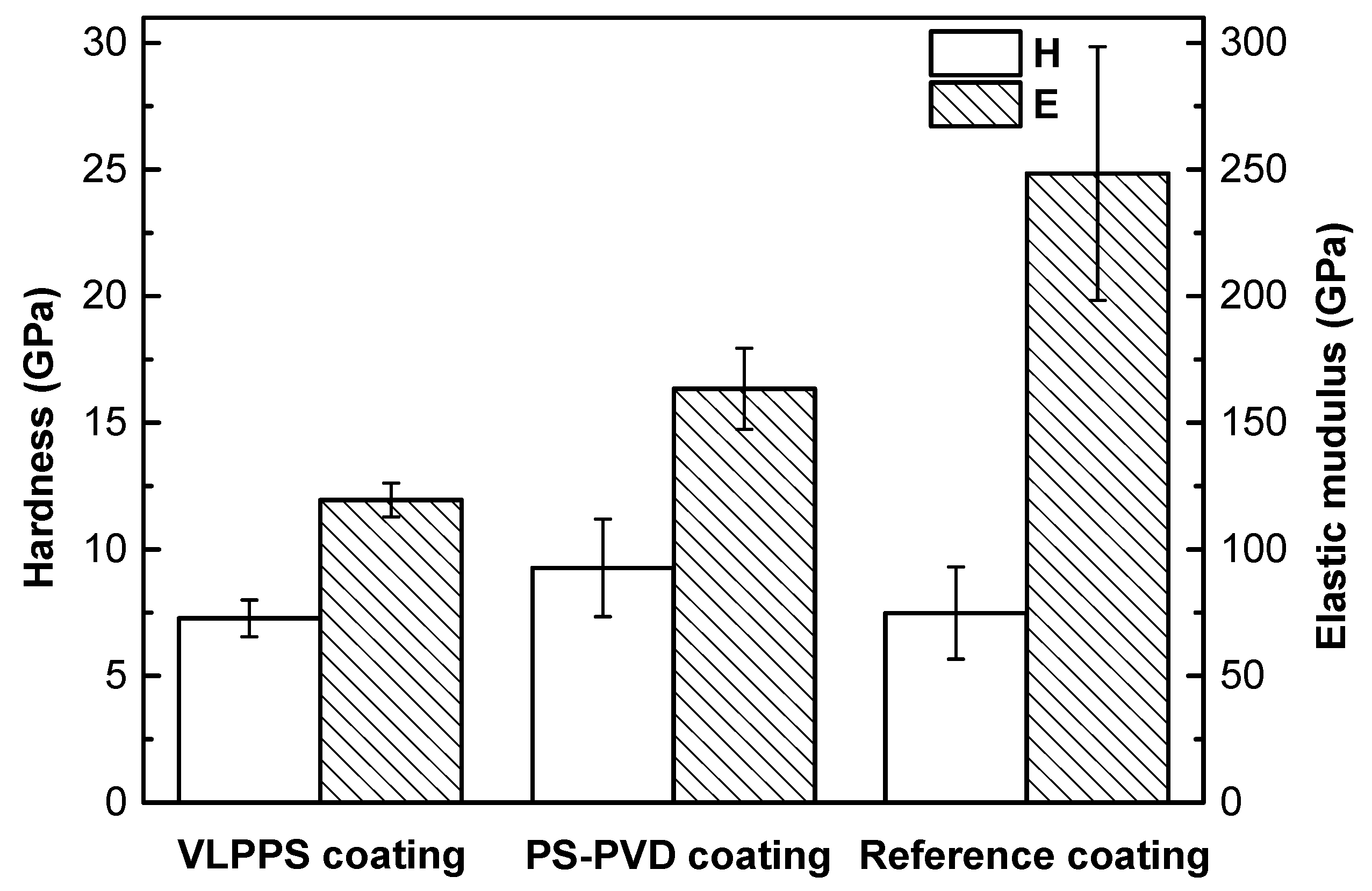
Figure 5 reveals the mechanical properties of GDC coatings. The hardness and elastic modulus of the PS-PVD coating (9.3 and 163.4 GPa, respectively) were higher than those of the VLPPS coating (7.3 and 123.6 GPa, respectively), suggesting that the density and degree of crystallinity could influence the mechanical properties of coatings. Higher density and degree of crystallinity always benefit the hardness and elastic modulus, and as the PS-PVD coating had a lower porosity with a higher degree of crystallinity, its hardness and elastic modulus were higher than those of the VLPPS coating. Compared with another reference GDC coating [
17], the microhardness of the VLPPS and PS-PVD coatings were close to the sintered sample. However, the elastic moduli of both sprayed coatings were lower than the sintered sample, because the density (≥98%) and degree of crystallinity of the sintered sample were much higher.
4. Conclusions
To summarize, an agglomerated GDC powder was prepared by spray drying, with an average particle size of 9.63 μm. Using the agglomerated powder, two GDC coatings were manufactured via VLPPS and PS-PVD. Although the morphologies of both coatings were dense, the deposition mechanisms of the two coatings were significantly different. The VLPPS coating was mainly formed by densely packed molten particles, while the PS-PVD coating was deposited by a mixed vapor phase and liquid splats. Moreover, the microhardness and elastic modulus of the PS-PVD coating were higher than those of the VLPPS coating, which could contribute to the higher density and better crystallinity. As the density and mechanical properties of the PS-PVD-prepared GDC coating were higher, it can be inferred that the PS-PVD coating is more appropriate for LT-SOFC application. To verify this, the electrical conductivities of the GDC coatings will be characterized in the following work.


