Article

Bioactive Coating on Titanium Dental Implants for Improved Anticorrosion Protection: A Combined Experimental and Theoretical Study

1
Department of Electrochemistry, Faculty of Chemical Engineering and Technology, University of Zagreb, Marulićev trg 19, 10000 Zagreb, Croatia
2
Division of Materials Physics, Centre of Excellence for Advanced Materials and Sensing Device, Ruđer Bošković Institute, Bijenička cesta 54, 10002 Zagreb, Croatia
3
Division of Physical Chemistry, Ruđer Bošković Institute, Bijenička cesta 54, 10002 Zagreb, Croatia
4
Division of Materials Chemistry, Ruđer Bošković Institute, Bijenička cesta 54, 10002 Zagreb, Croatia
5
Adentro dental studio, Petrova ul. 67, 10000 Zagreb, Croatia
*
Authors to whom correspondence should be addressed.
Coatings 2019, 9(10), 612; https://doi.org/10.3390/coatings9100612
Submission received: 26 July 2019 / Revised: 6 September 2019 / Accepted: 23 September 2019 / Published: 25 September 2019
(This article belongs to the Special Issue Anticorrosion Protection of Nonmetallic and Metallic Coatings)

Abstract

:
In recent years, extensive studies have been continuously undertaken on the design of bioactive and biomimetic dental implant surfaces due to the need for improvement of the implant–bone interface properties. In this paper, the titanium dental implant surface was modified by bioactive vitamin D3 molecules by a self-assembly process in order to form an improved anticorrosion coating. Surface characterization of the modified implant was performed by field emission scanning electron microscopy (FE-SEM), attenuated total reflection Fourier transform infrared spectroscopy (ATR-FTIR), and contact angle measurements (CA). The implant’s electrochemical stability during exposure to an artificial saliva solution was monitored in situ by electrochemical impedance spectroscopy (EIS). The experimental results obtained were corroborated by means of quantum chemical calculations at the density functional theory level (DFT). The formation mechanism of the coating onto the titanium implant surface was proposed. During a prolonged immersion period, the bioactive coating effectively prevented a corrosive attack on the underlying titanium (polarization resistance in order of 107 Ω cm2) with ~95% protection effectiveness.

Graphical Abstract

1. Introduction

Titanium and its alloys are the most commonly used implant materials, which represent gold standards for dental implant fabrication due to their exceptional combination of high corrosion resistivity, favourable mechanical properties, and biocompatibility [1,2,3]. Although the implantation success of titanium dental implants is high, complications still occur. There is an increasing number of papers regarding titanium hypersensitivity, skin allergies such as contact dermatitis, eczema, and immune reactions appearing after implant fixation [4,5,6,7]. It is also known that osseointegration problems in patients suffering from osteoporosis or other bone-related problems are one of reasons for unsuccessful implantation of dental implants [8]. Therefore, there is a need for continuous improvement of dental implant material characteristics as well as their design to ensure long-term integration of implants into the jaw.
Surface modification, which in recent years has been in the focus of extensive research, is one of strategies for improving corrosion resistivity, biocompatibility, and bioactivity of dental implants [3,8,9,10]. It has been reported that the presence of inorganic coatings such as calcium phosphates [11] or hydroxyapatite [12,13] promotes and accelerates bone formation in implant surroundings. Nano-hydroxyapatite is used as a single coating or in a combination with collagen, bio glass, or titanium dioxide in a composite coating to imitate the bio-environment of native bones [14]. Functionalization of the implant surfaces with organic or bioactive molecules promotes the adhesion of various cells [3]. Coatings based on bisphoshonates—drugs for bone disease treatments—act osseoinductively and improve bone–implant connections [8,15,16].
According to currently available data, there is a great interest among dental surgeons and implantologists in analyzing relationships between vitamin D3 and the osseointegration process [17,18]. Besides a known role of vitamin D3 in bone metabolism, D3 is also very relevant for the normal functioning of the immune system, which is of particular importance for a successful integration of a dental implant in surrounding bone tissue [17]. Therefore, in this study, the titanium dental implant surface was modified by a bioactive vitamin D3 coating prepared by a self-assembly process. The main goal was (i) to make the dental implant surface more osseoinductive and simultaneously (ii) more corrosion resistant during exposure to aggressive media (oral cavity fluids). Based on the results of a combined electrochemical–theoretical study, the bioactive coating formation mechanism was clarified as well as the coating’s influence on electrochemical behavior of the titanium implant during immersion in an artificial saliva solution. To the best of our knowledge, the present study shows for the first time the results of an integrated theoretical–experimental approach, which contribute to a fundamental understanding of bioactive and protective coating formation and predict overall electrochemical stability of modified dental implants in oral cavity fluids.

2. Materials and Methods

2.1. Material and Chemicals

The Ankylos® C/X training implant A11 (length: 11 mm, diameter: 3.5 mm, Dentsply Friadent GmbH, Mannheim, Germany), denoted as Ti-implant, was the object of the study and it was used as-received. According to manufacturer’s data, the implant is made of pure titanium grade 2, ISO 5832-2:2018 [19], and its chemical composition is presented in Table 1 [20].
Vitamin D3 drops (ChildLife®, Los Angeles, CA, USA) were used as-received. 122 μmol dm−3 cholecalciferol (vitamin D3) in aqueous glycerol solution was used for modification of the Ti-implant surface. The chemical structure of the vitamin D3, C27H44O, is presented in Figure 1.

2.2. Formation of Bioactive Coating

Before modification, the surface of as-received Ti-implant was ultrasonically cleaned with acetone (p.a., Gram-Mol, Zagreb, Croatia) and redistilled water, degreased in absolute ethanol (p.a., Gram-Mol, Croatia), and dried in a stream of nitrogen (99.999%, Messer, Bad Soden, Germany). The D3 vitamin layer onto the Ti-implant surface was prepared by a self-assembly method. The Ti-implant was immersed in an aqueous glycerol solution of vitamin D3 at 24 ± 2 °C during 24 h. Afterwards, the coated Ti-implant was dried in a regular air-convection oven (Instrumentaria, Sesvete, Croatia) at 70 °C for 5 h. That well-known procedure [21,22] enhanced the adhesion and stability of the coating due to the conversion of the hydrogen-bonded intermediate into the stable coating with a chemical Ti–O bond by an acid-base condensation mechanism. The formation mechanism as well as the type of interactions were accurately corroborated by DFT (Section 3.3). Finally, the modified sample was rinsed with absolute ethanol, redistilled water, and dried in a stream of nitrogen. The prepared modified sample, denoted in the text as the Ti-implant/bioactive coating, was used for further characterization.

2.3. Characterisation Methods

The morphology characteristics of unmodified and modified Ti-implant surfaces were examined by a thermal field emission scanning electron microscope (model JSM-7000F, Jeol Ltd., Tokyo, Japan) at 15 kV.
The contact angles on investigated Ti-implant surfaces were measured with a drop of 1 μL Milli-Q® water (Milli-Q® Direct 8 Water Purification System, Merck, Darmstadt, Germany) at ambient atmospheric conditions using a contact angle system OCA 20 (Dataphysics Instruments GmbH, Filderstadt, Germany). Values reported are the average of three measurements taken at smooth upper part of the implant (without threads) after initial period of 10 s stabilization.
The ATR-FTIR measurements were performed by a Tensor II spectrometer (Bruker Optik GmbH, Ettlingen, Germany) over the range of 4000–340 at 4 cm−1 scan step and total 16 scans per measurement.
Electrochemical characterization of unmodified and modified Ti-implant samples was assessed by electrochemical impedance spectroscopy (EIS). A standard three-electrode cell (Corrosion Cell 6.1415.250, volume 50–150 mL, Metrohm Autolab B.V., Utrecht, Netherlands) was utilized with the Ti-implant material as a working electrode (an area of 0.98 cm2 exposed to the electrolyte solution). A large-area Pt electrode served as a counter electrode and a reference electrode, to which all potentials in the paper are referred, was an Ag|AgCl, 3.0 mol dm−3 KCl (E = 0.210 V vs. standard hydrogen electrode, SHE). Barrier properties of unmodified and modified Ti-implants were evaluated in solution based on Fusayama artificial saliva (0.4 g dm−3 NaCl, 0.4 g dm−3 KCl, 0.6 g dm−3 CaCl2·2H2O, 0.58 g dm−3 Na2HPO4·2H2O, and 1 g dm−3 urea), pH 6.8 [23], prepared from p.a. grade chemicals and redistilled water. Prior to EIS measurements, the Ti-implant electrode was stabilized for 1 h, 1, and 7 days at the open circuit potential, EOC, in the electrolyte solution.
EIS measurements were performed subsequently in the frequency range from 105 to 10−3 Hz at EOC with an ac voltage amplitude of ±5 mV using Solartron 1287 potentiostat/galvanostat with Solartron FRA 1260 (Solartron Analytical, Farnborough, UK) controlled by ZPlot® software (v. 3.5e, Southern Pines, Moore, NC, USA). The complex non-linear least squares (CNLS) fit analysis software [24] was employed to model the experimental data obtained. The values of the elements of the proposed electric equivalent circuit (EEC) were derived with χ2 values less than 5 × 10⁻³ (errors in parameter values of 1–3%) using ZView® software (v. 3.5e, Southern Pines, USA).

2.4. Computational Details

All calculations were performed by means of quantum chemical calculations at the density functional theory (DFT) level using the Gaussian 09 program (revision D1) [25]. The small (TiO2)10 nanocluster served as a credible model for all possible molecular surface/bioactive molecule interaction predictions [26,27]. The M06 functional designed by Truhlar’s group was selected [28,29,30]. For the geometry optimization the 6-31+G(d,p) + LANL2DZ basis set was utilized, which means that the Pople’s 6-31+G(d,p) double-ξ basis set was chosen for O, H, C atoms and the LANL2DZ basis for the transition-metal (Ti) atoms [31]. Frequency calculations were done under the harmonic approximation on all the optimized structures at the same level of theory, with no scaling in order to confirm the true minima of the structures. The final single point energies were obtained using a highly flexible 6-311++G(2df,2pd) basis set for the O, H, C atoms, while the same LANL2DZ ECP type basis set for titanium atoms was employed. To evaluate the bulk solvent effects (1,2-ethandiol as a glycerol approximation, ε = 40.245), the implicit SMD polarizable continuum solvation model [32] was employed.
The Gibbs free energy interactions, ∆G*INT were computed as the difference between the total free energy (G*AB) of the resulting (AB) structure and the sum of the total free energies (G*A + G*B) of the associating units A and B (Tables S1–S4 in Supplementary Materials).
The topological analysis of the charge density distribution was performed by employing AIMALL software package [33] using Bader’s quantum theory of atoms in molecules (QTAIM) [34] with SMD/M06/6-31+G(d,p) + LANL2DZ wave function derived from the optimization. A detailed description of the computational modelling is given in the Supplementary Material.

3. Results and Discussion

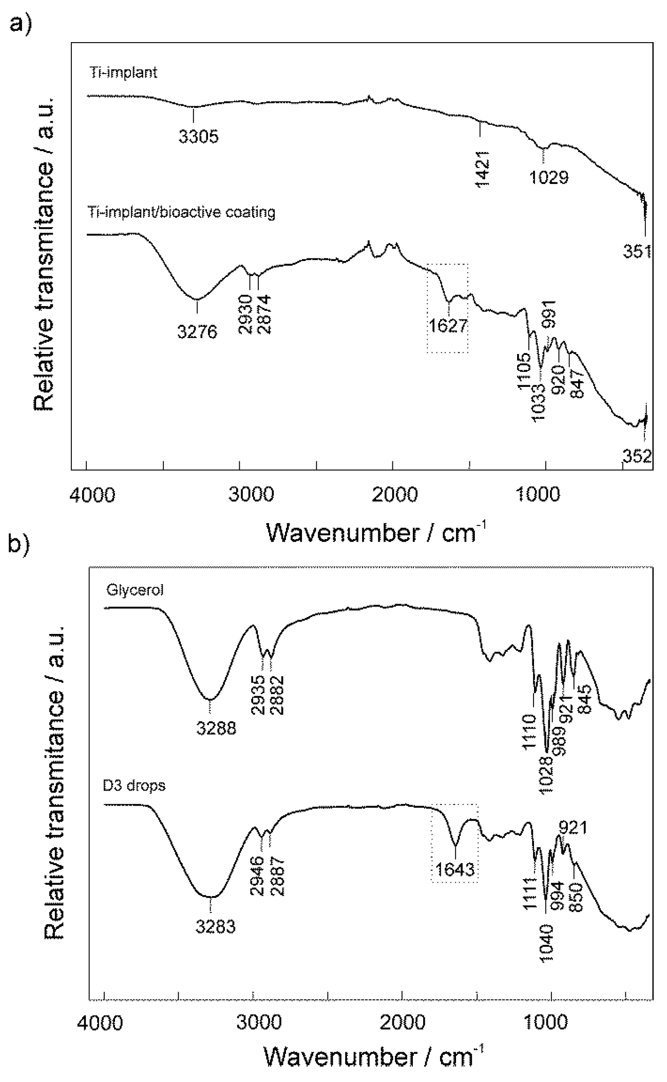
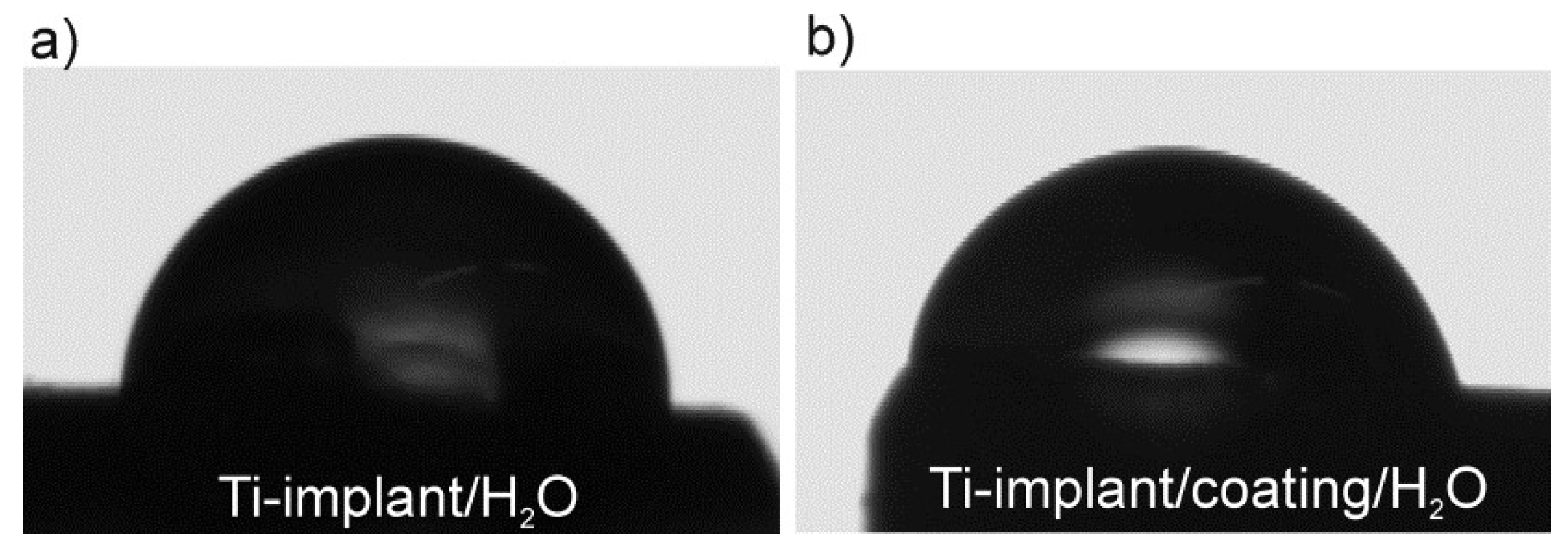
3.1. Surface Characterization of the Unmodified and Modified Ti-Implant Samples

The surface morphology of both unmodified (as-received Ti-implant) and modified (Ti-implant/bioactive coating) samples was investigated by using FE-SEM and is presented in Figure 2. SEM images of the Ti-implant surface present a inhomogeneous microstructured surface layer exhibiting different size cavities and defects and is characterized by overall microroughness (Figure 2a,b). According to the manufacturer’s data, the implant surface was grit-blasted and high-temperature etched and this microstructure is commercially known as Friadent® plus microstructure. The resulting surface favors the highly rapid apposition of bone-inducing cells on the implant [19]. Observed morphology is in accordance with SEM results reported by R. Smeets at al. [8], F. Rupp et al. [35], and T.J. Webster et al. [36]. The surface morphology did not change significantly upon the bioactive coating on the Ti-implant surface preparation. Since the D3 layer thickness was about 0.6 nm, according to the DFT results, the level of possible morphology differentiation by SEM was very low.
The surface chemistry of the unmodified (Ti-implant) and modified (Ti-implant/bioactive coating) samples was examined by ATR-FTIR and recorded spectra are presented in Figure 3a. The spectrum of the Ti-implant/bioactive coating sample was recorded immediately after the final step of the coating formation (see Section 2.2). A confirmation of a successful formation of the bioactive coating on the Ti-implant surface was deduced based on the presence of vitamin D3 functional group bands in investigated samples spectra, which indicates chemisorption on the Ti-implant surface, as will be given below.
In the Ti-implant sample ATR-FTIR spectrum, a broad band observed at 3305 cm−1 is characteristic to the stretching vibration of adsorbed water on the Ti-implant surface. A vibration band characteristic for the Ti–OH appeared at 1029 cm−1. A band at 1421 cm−1 arising from TiO2 lattice vibration and the bands located in the range from 350–1000 cm−1 were related to the Ti–O stretching vibrations [37,38]. According to the described bands, the Ti-implant surface is covered by a TiO2 layer.
In Figure 3a a spectrum of the Ti-implant/bioactive coating sample is presented. ATR-FTIR spectra of vitamin D3 and glycerol were also recorded since vitamin D3 drops used for the bioactive coating formation contained glycerol as a solvent (Figure 3b). As can be seen, spectra of both compounds are very similar and are in accordance with the literature data [39]. A clear difference is a peak at 1643 cm−1 that is assigned to the H–C=CH stretching vibrations characteristic to vitamin D3.
A spectrum of the Ti-implant/bioactive coating (Figure 3a) contains observed distinctive bands for vitamin D3 and glycerol. A presence of broader band at 1627 cm−1, characteristic for vitamin D3 molecule, confirms a successful formation of the vitamin D3 layer on the Ti-implant surface. Shifts of all bands to lower wavenumbers also indicate an attachment (chemisorption) of vitamin D3 molecules to the Ti-implant surface. A peak at 351 cm−1 of TiO2 is visible due to relatively low D3 layer thickness, according to the DFT results.
Since the ATR-FTIR spectra of D3 and glycerol molecules exhibited high degree of resemblance and intermolecular interactions exist between both molecules (DFT results, Section 3.3), there is a possibility that both compounds are simultaneously bonded to the implant surface as a two layer-structured coating, as will be discussed later (Section 3.3). Therefore, it is impossible to accurately determine the interaction nature and type between vitamin D3 molecules and Ti-implant substrates only from the observed band shifts. Further experimental characterization as well as theoretical DFT calculations were carried out to accurately determine the structure of the bioactive coating formed onto the Ti-implant surface.
A study of the wetting properties of implant surfaces is very important for the understanding of a complex reaction series occurring during the initial contact between implant and body fluids [8,35]. In this study, wettability measurements were conducted in order to evaluate level of a bioactive coating formation success. A static contact angle of water, θ, was measured on the unmodified (Ti-implant) and modified Ti-implant (Ti-implant/bioactive coating) surfaces. Measurements were carried out at upper smooth part of the implant body and corresponding micrographs are presented in Figure 4.
The higher value of contact angle, θ = 87.5 ± 2.2°, was obtained on the Ti-implant surface in comparison to the value obtained on the Ti-implant/bioactive coating surface, θ = 60.4 ± 1.5°. Wetting properties of the Ti-implant surface were changed by a presence of a coating and these results were confirmation of a successful formation of the bioactive coating on the implant surface. The surface modification induced a change from a hydrophobic (Ti-implant) to hydrophilic surface character (Ti-implant/bioactive coating). Therefore, the wetting properties of the modified Ti-implant surface are predominantly affected by the hydrophilic –OH functional groups oriented in the upper part of the coating, possibly originating from glycerol molecules, as will be discussed on the basis of DFT results (see Section 3.3).

3.2. Electrochemical Characterization of the Unmodified and Modified Ti-Implant Samples

The electrochemical behavior of the unmodified and D3 vitamin modified Ti-implant surfaces, as one of prerequisite factors for dental implant biocompatibility in contact with aggressive oral cavity fluids and hence successful implantation process, was studied under in vitro conditions of real dental implant application. Employing a non-destructive method of electrochemical impedance spectroscopy (EIS), electrochemical stability of investigated samples during different immersion times (shown in Figure 5) was monitored in situ in an artificial saliva electrolyte solution at EOC over the wide frequency range and the obtained impedance spectra are given in the form of Bode magnitude and phase angle plots in Figure 5a,b. The impedance data were analyzed in terms of the electric equivalent circuits (EECs) that are presented in Figure 5c,d and the impedance parameter values are provided in Table 2 and Table 3.
In the EECs employed, the constant-phase element, CPE, was used to describe a non-ideal capacitance behavior in order to compensate non-homogeneity in the system (inhomogeneous current flow, capacitance dispersion, etc.) [40,41,42]. The impedance of CPE can be expressed as ZCPE = [Q(jω)n]−1 where Q and n are parameters associated with CPE. For CPE exponent n = 1, the frequency–independent CPE parameter Q represents the capacity of the interface. For n ≠ 1, the system shows behavior that has been attributed to surface heterogeneity, the presence of surface films, or to continuously distributed time constants for charge–transfer reactions [40]. The corresponding interface capacitance values were calculated according to Brug’s relation [41]:
Q = Cn(RΩ−1 + R−1)1 − n
The EIS data of the unmodified Ti-implant (Ti-implant/oxide film/artificial saliva interface) were fitted to the EEC with two time constants (Figure 5c) and the parameter values are presented in Table 2. The EEC used is commonly applied to analyze impedance results of Ti and Ti-alloys covered with a bi-layer structure of oxide film [22,43,44,45,46,47,48]. The high/middle frequency time constant (R1-CPE1) describes the characteristics of the outer porous layer of the oxide film. R1 represents the resistance and CPE1 the capacitance of the outer layer. The low frequency time constant (R2-CPE2) is related to the inner barrier layer of the oxide film, predominately containing titanium(IV) oxide [1,44,49]. R2 represents the resistance and CPE2 the capacitance of the barrier layer. R is the ohmic (electrolyte) resistance. The polarization (corrosion) resistance, Rp, is the sum of R1 and R2 resistance contributions and determines the overall corrosion resistance of the oxide-covered Ti-implant [50].
As can be seen from Figure 5a and Table 2, the electrochemical stability of the Ti-implant sample was significantly decreased during an exposure to an artificial saliva solution, which was particularly reflected in R1 and R2 values. During the initial short immersion period, an oxide film on the Ti-implant surface possessed high protective properties (high Rp value). Since the artificial saliva solution represents an aggressive medium, a high amount of chloride ions affects the oxide film properties and accelerates the titanium corrosion (degradation) process during a prolonged immersion period [51]. Calculated parameters, especially R1 values, indicate that the contribution of the outer layer of the oxide film to the electrochemical behaviour is rather imperceptible, and the overall EIS response is dominated by the inner barrier layer of the oxide film, which is in accordance with previously reported results [43,44].
The Bode plots of the Ti-implant/bioactive coating sample measured after specified artificial saliva exposure times are presented in Figure 5b. The brief inspection of the spectra points to the different impedance behavior of vitamin D3 modified Ti-implant surface in comparison to the unmodified Ti-implant surface. Hence, EEC with only one time constant was employed to analyze the EIS data (Figure 5d), with Rc and Cc attributing as the resistance and capacitance of the bioactive coating formed. The bioactive coating structure is very compact and well-ordered due to the presence of vitamin D3 layer over the oxide covered Ti-implant surface, as was confirmed by the DFT calculation results (Section 3.3) and both of layers contribute to the overall corrosion resistance of the underlying Ti-implant. The resistance Rc represents the polarization resistance, Rp, of the investigated system. The fitted values are presented in Table 3.
As can be seen, the dependence of phase angle versus log f points to a capacitive behavior of the coated Ti-implant sample over the wider frequency range in comparison to the unmodified Ti-implant sample. Besides, higher low frequency magnitude values that remain almost unchanged during the investigated period of 7 days indicate improved electrochemical stability and corrosion protection of the Ti-implant upon bioactive coating formation.
However, deep insight into phase angle versus log f dependence, as a structural sensitive parameter, reflects possible structural changes inside the bioactive coating during first day of sample immersion into the artificial saliva solution. This rearrangement/reorganization inside the bioactive coating induced a slight deterioration of protective properties, as can be seen from Rc values (Table 3). After a prolonged immersion period (from 1st to 7th day), EIS responses did not change significantly. Obviously, observed coating rearrangement/reorganization was induced by an initial contact between modified Ti-implant surface and electrolyte solution. According to the literature, structural reorganization that modulates electrical properties is known for self-assembled surface layers and can be stimulated by potential or by polarity and wettability of the terminal functional group of the layer molecules [52,53]. On the basis of DFT calculations (Section 3.3), weak intermolecular interactions between glycerol and D3 molecules are present and they result in glycerol molecules orientation in the outer part of the bioactive coating. Thus, glycerol–OH terminal functional groups affect the polarity and wettability of the coating formed on the Ti-implant surface, which was observed in the contact angle value (Figure 4). Probably, there is a possibility of stronger interaction between the glycerol ‒OH group and electrolyte components that caused a glycerol withdrawal from the Ti-implant surface and simultaneous structural changes inside the bioactive coating, as was confirmed by DFT (Section 3.3). The coated Ti-implant surface was perturbed and small defects in the coating’s structure probably occurred. Consequently, ions/water molecules could penetrate into the coating, hence causing a decrease in Rc values after a one-day immersion. During this first day, the coating structure again achieved the most stable conformation resulting in unchanged Rc values. It should be stressed that, albeit the Rp value decrease was observed due to the structural organization occurrence, the overall coating resistance (the sum of oxide film + D3 layer resistances) inversely proportional to the corrosion rate, remained in order of 107 Ω cm2 and imparted sufficient corrosion protection to the underlying Ti-implant material.
The corrosion protection effectiveness, η, of the bioactive coating formed on the Ti-implant surface was calculated using the relation:
η = (Rp (modified)Rp (umodified))/Rp (modified)
where Rp (unmodified) and Rp (modified) are the polarization resistances of unmodified and modified Ti-implants. The protection effectiveness values are presented in Table 3.
According to EIS results, protective properties of the unmodified, as-received Ti-implant (Ti-implant/oxide film) were significantly deteriorated during its immersion into an artificial saliva solution. On the other hand, the D3 layer, prepared by self-assembly process on the oxide-covered Ti-implant surface (Ti-implant/bioactive coating), behaved as an excellent barrier to the transport of corrosive ions/molecules from the bulk electrolyte to the Ti-implant surface during a prolonged exposure. Additionally, vitamin D3 molecules are bioactive molecules that can promote and accelerate an osseointegration process. Thus this bioactive, and at the same time, highly protective coating can serve as a good candidate for biocompatible Ti dental implants, enabling a pivotal role in the successful implantation process.

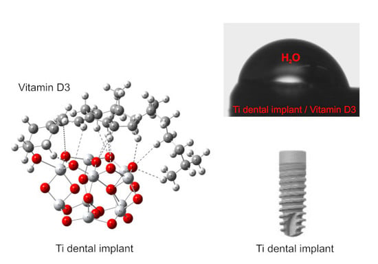
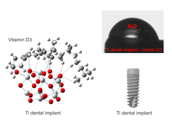
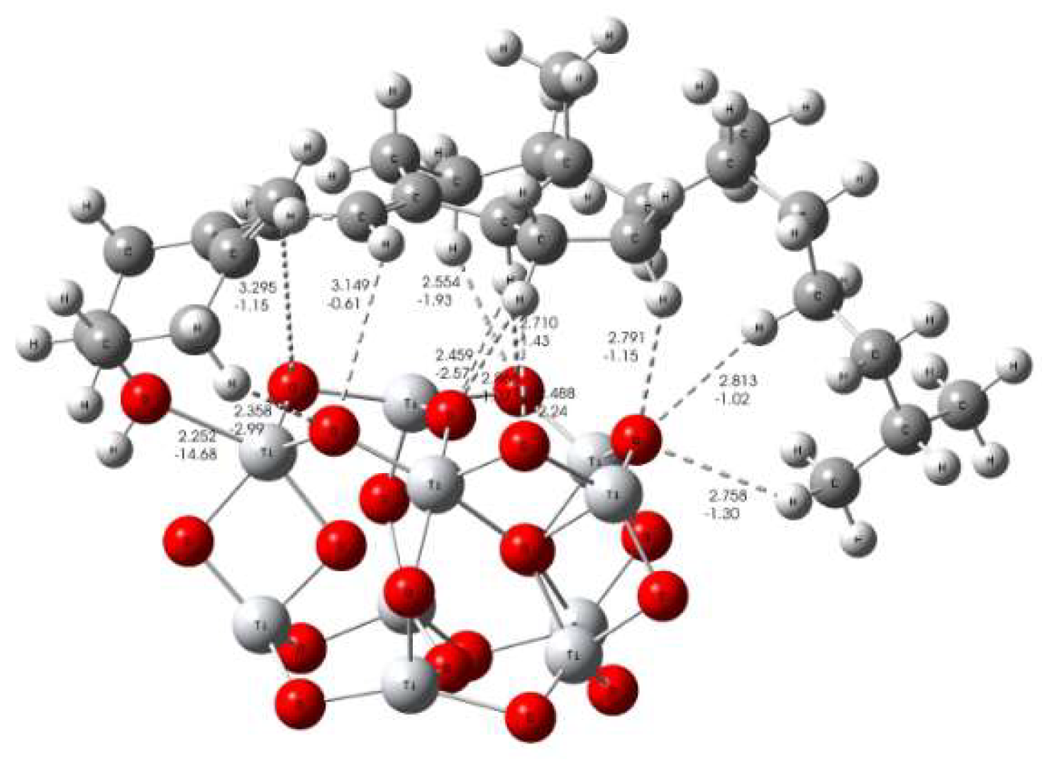
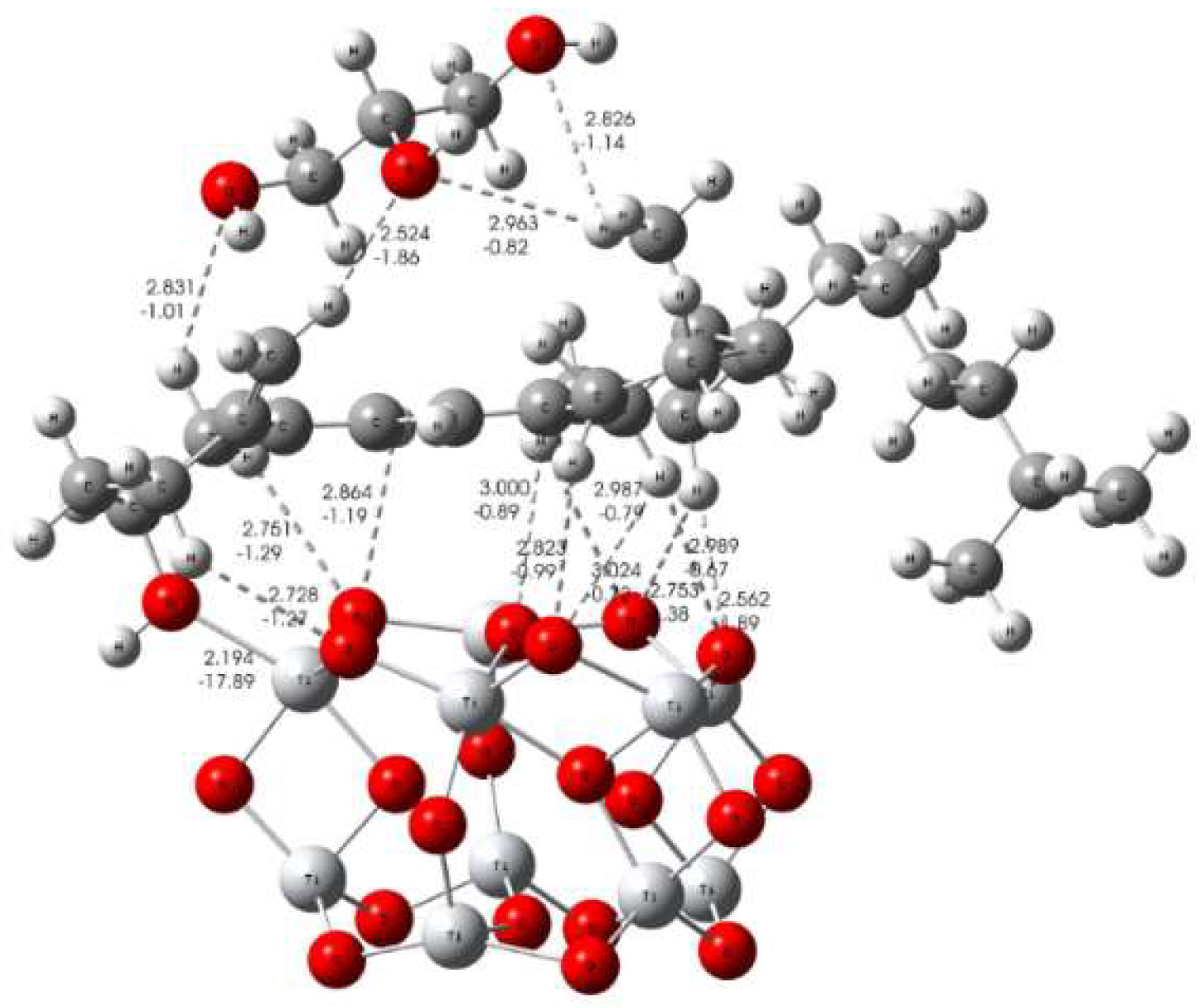
3.3. Formation Mechanism of Bioactive Implant Coating

Notwithstanding the part of the formation mechanism that has been discussed above in considering experimental results, a more detailed theoretical study of Ti-implant surface/bioactive molecule interactions is still needed to fully clarify the coating formation mechanism. The experimental findings were corroborated by means of DFT calculations based on effects of cholecalciferol (D3 vitamin) as well as glycerol as its alcoholic solvent in pharmaceutical composition of vitamin D3 solution. The small (TiO2)10 nanocluster served as a credible model for all possible molecular Ti-implant surface/bioactive molecule interaction predictions [26,27]. There is a possibility that the presence of other kinds of Ti-implant surface/molecule interactions (due to the presence of glycerol solvent) except the (TiO2)10–cholecalciferol interaction could be responsible for influencing the coating formation mechanism. Hence, the implant surface/bioactive molecule interactions were investigated considering the results obtained from a computational study of Gibbs free energies of (TiO2)10–cholecalciferol, (TiO2)10–cholecalciferol–glycerol, as well as (TiO2)10–glycerol molecular interactions (ΔG*INT). One should mention that only the most thermodynamically stable structures are discussed here.
Different binding interactions were established, involving the processes of the (TiO2)10–cholecalciferol interaction. The interactions, which involve Ti–O bonding and C–H∙∙∙O hydrogen bonding, are shown in Figure 6. When Ti–O and hydrogen bonds are formed, the free energies of (TiO2)10–cholecalciferol molecular interactions are released (ΔG*INT = −6.64 kcal mol−1). The (TiO2)10–cholecalciferol interaction has been found to be a spontaneous exergonic process. The formation of such a completely enclosed structure of (TiO2)10–cholecalciferol, with a high coverage level of the (TiO2)10 surface, is likely a consequence of the synergistic effect of all the interactions mentioned above. Namely, the most stable structure of (TiO2)10–cholecalciferol possesses a Ti–O bond (dTi–O = 2.252 Å, ETi–O = −14.68 kcal mol−1) which is stabilized by eleven weaker C–H∙∙∙O hydrogen bonds (EO∙∙∙H ranges from −0.61 to −2.99 kcal mol−1; dO∙∙∙H ranges from 3.295 to 2.358 Å). The Ti–O bond is attributed to an ionic (polar coordinate) type of interacting, according to Δ2ρ (rc) > 0 and H(rc) > 0.
The possible formation of the (TiO2)10–cholecalciferol–glycerol structure involves different binding interactions in relation to the (TiO2)10–cholecalciferol formation mechanism. That difference is probably a consequence of higher steric as well as energetic requirements needed for the (TiO2)10–cholecalciferol–glycerol molecular interactions. These interactions require an additional step of releasing a few C–H∙∙∙O hydrogen bonds in stable (TiO2)10–cholecalciferol structure (Figure 6) due of the access of one or more glycerol molecules. Namely, when the (TiO2)10–cholecalciferol–glycerol was formed, the cholecalciferol could have be attached to the (TiO2)10 cluster in different way related to (TiO2)10–cholecalciferol structure, as shown in Figure 6 and Figure 7. It is important to note the large capacity of the cholecalciferol in the (TiO2)10–cholecalciferol structure to attract glycerol molecules due to stronger O–H∙∙∙O hydrogen and weaker C–H∙∙∙O hydrogen bonds (EO∙∙∙H ranges from –0.82 kcal to –1.86 kcal mol−1; dO∙∙∙H ranges from 2.963 to 2.524 Å), as shown in Figure 7. However, the formation of the (TiO2)10-cholecalciferol-glycerol structure is slightly endergonic process (ΔG*INT = 5.51 kcal mol1) indicating that it could act only as a “coating intermediate”, which is in a good agreement with FT-IR spectroscopy and contact angle measurement results (Figure 3 and Figure 4). The most probably, as can be seen from the EIS response after one-day immersion of the modified Ti-implant (Figure 5b), this “coating intermediate” was responsible for temporal coating structural rearrangement that was reflected in the coating resistance value (Rc value, Table 3).
Based on experimental findings and DFT calculations, it seems that is not possible to predict the mechanism responsible for bioactive coating formation in the presence of solvent molecules solely based on the aspect of thermodynamic stability of the coating intermediate. For a more detailed/accurate coating formation mechanism, additional species present in the artificial saliva solution (simulated oral cavity physiological solution) should be taken into consideration due to their possible stronger coordination ability, which could replace the weaker hydrogen bonds between cholecalciferol and glycerol.
Taking into account the calculated energy values of common bonding (Ti–O) and eleven weaker C–H∙∙∙O hydrogen bonds, as well as ΔG*INT, it can be concluded that cholecalciferol (D3 vitamin) molecules bond to the oxide-covered Ti implant surface displaying a high coverage level. Consequently, the bioactive coating on the Ti dental implant surface is very stable and resistant to the aggressive environment of artificial saliva, according to the EIS findings. Because of well-known bioactivity and, in this study, the proven protective effectiveness of D3 vitamin as a coating, a described strategy can be applied for a design of real dental implants of improved biocompatibility and osseointegrity.

4. Conclusions

In this study, the titanium dental implant was functionalized with bioactive molecules of vitamin D3 (cholecalciferol) to make its surface more corrosion resistant to aggressive oral cavity fluids and at the same time more attractive for bone cell adhesion. An integrated experimental–theoretical approach for the characterization of the Ti dental implant/bioactive coating interface was applied.
ATR-FTIR spectroscopy and contact angle measurement results confirmed the presence of the D3 layer onto the oxide covered Ti-implant surface.
Coating’s formation mechanism was proposed, considering the DFT calculation results. D3 molecules possess an affinity to the titanium surface covered by the TiO2 layer and are bonded to the surface through a Ti–O bond (ETi–O = −14.68 kcal mol−1), which is stabilized by eleven weaker C–H∙∙∙O hydrogen bonds (EO∙∙∙H ranges from −0.61 to −2.99 kcal mol−1). This type of interactions resulted in a formation of the enclosed Ti-implant surface‒vitamin D3 structure with high surface coverage level.
The bioactive coating influence on protective properties of the Ti-implant was investigated in situ by using EIS during different exposure times to an artificial saliva solution. The presence of the D3 layer on the oxide covered Ti-implant surface significantly changed the structure of the electrified Ti-implant surface/bioactive coating/artificial saliva interface compared to the Ti-implant surface/oxide film/artificial saliva interface.
During a prolonged immersion period, the stable bioactive coating effectively prevented the Ti-implant surface from contacting aggressive ions present in the artificial saliva solution. After a 7 day immersion period, the protection effectiveness amounted 97.5%.
Dental implant design that simultaneously stimulates an implant–bone connection creation (osseointegration) and enables good anticorrosion protection during an exposure to oral cavity fluids is desirable from a real application point of view.

Supplementary Materials

The following are available online at https://www.mdpi.com/2079-6412/9/10/612/s1, Computational modelling, Table S1: Formation of the most stable (TiO2)10−cholecalciferol(a), (TiO2)10−cholecalciferol−glycerol (b) and (TiO2)10−glycerol species(c). Standard state (1M) free energies of interaction ΔrG*INT computed by using the SMD solvation model at the M06/6-311++G(2df,2pd) + LANL2DZ// M06/6-31+G(d,p) + LANL2DZ level of theory, Table S2: Bond lengths (d), energies (E) and QTAIM properties of the selected bonds in the most stable (TiO2)10−cholecalciferol, (TiO2)10−cholecalciferol−glycerol and (TiO2)10−glycerol structures, Table S3: Total electronic energy, ETotsoln, obtained at the SMD/M06/6-311++G(2df,2pd) + LANL2DZ//SMD/M06/6-31+G(d,p) + LANL2DZ level of theory, thermal correction to the Gibbs free energy, ΔG*VRT,soln, obtained at the SMD/M06/6-31+G(d,p) + LANL2DZ level of theory, and total free energy, G*X, (G*X = ETotsoln + ΔG*VRT,soln) in 1,2-ethandiol media of the investigated species (all energies in hartree), Table S4: Optimized Cartesian coordinates of the calculated systems (given as XYZ format).

Author Contributions

Conceptualization, A.Š. and Ž.P.; Formal Analysis, J.K. and I.D.; Investigation, J.K., I.D., N.M. and Ž.P.; Methodology, J.K., A.Š., I.D. and Ž.P.; Resources, J.K., I.D., N.M. and M.P.; Supervision, A.Š. and Ž.P.; Writing–Original Draft, J.K., A.Š. and Ž.P.; Writing–Review and Editing, J.K., A.Š. and Ž.P.

Funding

This research received no external funding.

Acknowledgments

This work has been partially supported by SAFU, project KK.01.1.1.01.0001. The authors would like to thank the Zagreb University Computing Centre (SRCE) for generously granting computational resources on the ISABELLA cluster (isabella.srce.hr). The authors also thank Mirela Leskovac for her valuable comments in wettability measurements.

Conflicts of Interest

The authors declare no conflict of interest.

References

  1. Eliaz, N. Corrosion of Metallic Biomaterials: A Review. Materials 2019, 12, 407. [Google Scholar] [CrossRef] [PubMed]
  2. Hansen, D.C. Metal Corrosion in the Human Body: The Ultimate Bio-Corrosion Scenario. Electrochem. Soc. Interface 2008, 17, 31. [Google Scholar]
  3. Gaviria, L.; Salcido, J.P.; Guda, T.; Ong, J.L. Current trends in dental implants. J. Korean Assoc. Oral Maxillofac. Surg. 2014, 40, 50–60. [Google Scholar] [CrossRef] [PubMed]
  4. Yan, H.; Afroz, S.; Dalanon, J.; Goto, N.; Hosoki, M.; Matsuka, Y. Metal allergy patient treated by titanium implant denture: A case report with at least 4-year follow-up. Clin. Case Rep. 2018, 6, 1972–1977. [Google Scholar] [CrossRef] [PubMed]
  5. Siddiqi, A.; Payne, A.G.T.; De Silva, R.K.; Duncan, W.J. Titanium allergy: Could it affect dental implant integration? Clin. Oral Implant. Res. 2011, 22, 673–680. [Google Scholar] [CrossRef] [PubMed]
  6. Syed, M.; Chopra, R.; Sachdev, V. Allergic Reactions to Dental Materials—A Systematic Review. J. Clin. Diagn. Res. 2015, 9, ZE04. [Google Scholar] [CrossRef] [PubMed]
  7. Sicilia, A.; Cuesta, S.; Coma, G.; Arregui, I.; Guisasola, C.; Ruiz, E.; Maestro, A. Titanium allergy in dental implant patients: A clinical study on 1500 consecutive patients. Clin. Oral Implant. Res. 2008, 19, 823–835. [Google Scholar] [CrossRef] [PubMed]
  8. Smeets, R.; Stadlinger, B.; Schwarz, F.; Beck-Broichsitter, B.; Jung, O.; Precht, C.; Kloss, F.; Gröbe, A.; Heiland, M.; Ebker, T. Impact of Dental Implant Surface Modifications on Osseointegration. BioMed Res. Int. 2016, 2016, 6285620. [Google Scholar] [CrossRef]
  9. Al Mugeiren, O.M.; Baseer, M.A. Dental Implant Bioactive Surface Modifiers: An Update. J. Int. Soc. Prev. Community Dent. 2019, 9, 1–4. [Google Scholar] [CrossRef] [PubMed]
  10. Tian, B.; Xie, D.B.; Wang, F.H. Corrosion behavior of TiN and TiN/Ti composite films on Ti6Al4V alloy in Hanks solution. J. Appl. Electrochem. 2009, 39, 447–453. [Google Scholar] [CrossRef]
  11. Yuan, H.; Yang, Z.; Li, Y.; Zhang, X.; De Bruijn, J.D.; De Groot, K. Osteoinduction by calcium phosphate biomaterials. J. Mater. Sci. Mater. Electron. 1998, 9, 723–726. [Google Scholar] [CrossRef]
  12. Sousa, L.L.; Ricci, V.P.; Prado, D.G.; Apolinario, R.C.; Vercik, L.C.; Rigo, E.C.; Fernandes, M.C.; Mariano, N.A. Titanium Coating with Hydroxyapatite and Chitosan Doped with Silver Nitrate. Mater. Res. 2017, 20, 863–868. [Google Scholar] [CrossRef] [Green Version]
  13. Łukaszewska-Kuska, M.; Krawczyk, P.; Martyla, A.; Hedzelek, W.; Dorocka-Bobkowska, B. Hydroxyapatite coating on titanium endosseous implants for improved osseointegration: Physical and chemical considerations. Adv. Clin. Exp. Med. 2018, 27, 1055–1059. [Google Scholar] [CrossRef] [PubMed]
  14. Choi, A.H.; Ben-Nissan, B.; Matinlinna, J.P.; Conway, R.C. Current perspectives: Calcium phosphates nanocoatings and nanocomposite coatings in dentistry. J. Dent. Res. 2013, 92, 853–859. [Google Scholar] [CrossRef] [PubMed]
  15. Rojo, L.; Gharibi, B.; McLister, R.; Meenan, B.J.; Deb, S. Self-assembled monolayers of alendronate on Ti6Al4V alloy surfaces enhance osteogenesis in mesenchymal stem cells. Sci. Rep. 2016, 6, 30548. [Google Scholar] [CrossRef] [PubMed]
  16. Hu, X.; Neoh, K.G.; Shi, Z.; Kang, E.-T.; Wang, W. An In Vitro Assessment of Fibroblast and Osteoblast Response to Alendronate-Modified Titanium and the Potential for Decreasing Fibrous Encapsulation. Tissue Eng. Part A 2013, 19, 1919–1930. [Google Scholar] [CrossRef] [PubMed]
  17. Trybek, G.; Aniko-Wlodarczyk, M.; Kwiatek, J.; Preuss, O.; Brodkiewicz, A.; Sinicyn, A.; Grzywacz, A. The effect of vitamin D3 on the osteointegration of dental implant. Balt. J. Health Phys. Act. 2018, 10, 25–33. [Google Scholar] [CrossRef]
  18. Satué, M.; Monjo, M.; Ronold, H.J.; Lyngstadaas, S.P.; Ramis, J.M. Titanium implants coated with UV-irradiated vitamin D precursor and vitamin E: In vivo performance and coating stability. Clin. Oral Implant. Res. 2016, 28, 424–431. [Google Scholar] [CrossRef]
  19. ISO 5832-2:2018 Implants for surgery - Metallic materials—Part 2: Unalloyed titanium; ISO: Geneva, Switzerland, 2018.
  20. Available online: https://www.upmet.com/products/titanium/cp-grade-2 (accessed on 25 June 2019).
  21. Gouzman, I.; Dubey, M.; Carolus, M.D.; Schwartz, J.; Bernasek, S.L. Monolayer vs. multilayer self-assembled alkylphosphonate films: X-ray photoelectron spectroscopy studies. Surf. Sci. 2006, 600, 773–781. [Google Scholar] [CrossRef]
  22. Petrović, Ž.; Katić, J.; Metikoš-Huković, M.; Dadafarin, H.; Omanovic, S. Modification of a Nitinol Surface by Phosphonate Self-Assembled Monolayers. J. Electrochem. Soc. 2011, 158, F159–F165. [Google Scholar] [CrossRef]
  23. Mellado-Valero, A.; Muñoz, A.I.; Pina, V.G.; Sola-Ruiz, M.F. Electrochemical Behaviour and Galvanic Effects of Titanium Implants Coupled to Metallic Suprastructures in Artificial Saliva. Materials 2018, 11, 171. [Google Scholar] [CrossRef] [PubMed]
  24. Boukamp, A. A Nonlinear Least Squares Fit procedure for analysis of immittance data of electrochemical systems. Solid State Ionics 1986, 20, 31–44. [Google Scholar] [CrossRef] [Green Version]
  25. Frisch, M.J.; Trucks, G.W.; Schlegel, H.B.; Scuseria, G.E.; Robb, M.A.; Cheeseman, J.R.; Scalmani, G.; Barone, V.; Mennucci, B.; Petersson, G.A.; et al. Gaussian 09, Revision D.01; Gaussian, Inc.: Wallingford, CT, USA, 2013. [Google Scholar]
  26. Allard, M.M.; Merlos, S.N.; Springer, B.N.; Cooper, J.; Zhang, G.; Boskovic, D.S.; Kwon, S.R.; Nick, K.E.; Perry, C.C. Role of TiO2 Anatase Surface Morphology on Organophosphorus Interfacial Chemistry. J. Phys. Chem. C 2018, 122, 29237–29248. [Google Scholar] [CrossRef]
  27. Qu, Z.-W.; Kroes, G.-J. Theoretical Study of Stable, Defect-Free (TiO2)n Nanoparticles with n = 10–16. J. Phys. Chem. C 2007, 111, 16808–16817. [Google Scholar] [CrossRef]
  28. Zhao, Y.; Thrular, D.G. The M06 suite of density functionals for main group thermochemistry, thermochemical kinetics, noncovalent interactions, excited states, and transition elements: Two new functionals and systematic testing of four M06-class functionals and 12 other functionals. Theor. Chem. Acc. 2008, 120, 215–241. [Google Scholar] [CrossRef]
  29. Zhao, Y.; Truhlar, D.G. Density Functionals with Broad Applicability in Chemistry. Acc. Chem. Res. 2008, 41, 157–167. [Google Scholar] [CrossRef] [PubMed]
  30. Zhao, Y.; Truhlar, D.G. Density Functional Theory for Reaction Energies: Test of Meta and Hybrid Meta Functionals, Range-Separated Functionals, and Other High-Performance Functionals. J. Chem. Theory Comput. 2011, 7, 669–676. [Google Scholar] [CrossRef]
  31. Wadt, W.R.; Hay, P.J. Ab initio effective core potentials for molecular calculations. Potentials for main group elements Na to Bi. J. Chem. Phys. 1985, 82, 284–298. [Google Scholar] [CrossRef]
  32. Marenich, A.V.; Cramer, C.J.; Truhlar, D.G. Universal Solvation Model Based on Solute Electron Density and on a Continuum Model of the Solvent Defined by the Bulk Dielectric Constant and Atomic Surface Tensions. J. Phys. Chem. B 2009, 113, 6378–6396. [Google Scholar] [CrossRef] [PubMed]
  33. Keith, T.A. AIMAll (Version 17.01.25). Available online: http://aim.tkgristmill.com/versionhistory.html (accessed on 12 February 2019).
  34. Bader, R.F.W. Atoms in Molecules: A Quantum Theory; Oxford University Press: Oxford, NY, USA, 1994. [Google Scholar]
  35. Rupp, F.; Scheideler, L.; Rehbein, D.; Axmann, D.; Geis-Gerstorfer, J. Roughness induced dynamic changes of wettability of acid etched titanium implant modifications. Biomaterials 2004, 25, 1429–1438. [Google Scholar] [CrossRef]
  36. Webster, T.J.; Ejiofor, J.U. Increased osteoblast adhesion on nanophase metals: Ti, Ti6Al4V, and CoCrMo. Biomatererials 2004, 25, 4731–4739. [Google Scholar] [CrossRef] [PubMed]
  37. Ferreira, C.C.; Pereira Ricci, V.; de Sousa, L.L.; Marianoa, N.A.; Campos, M.G.N. Improvement of Titanium Corrosion Resistance by Coating with Poly-Caprolactone and Poly-Caprolactone/Titanium Dioxide: Potential Application in Heart Valves. Mater. Res. 2017, 20, 126–133. [Google Scholar] [CrossRef] [Green Version]
  38. Baig, M.I.; Ingole, P.G.; Choi, W.K.; Lee, H.K. Synthesis and characterization of polyamide/polyester thin-film nanocomposite membranes achieved by functionalized TiO2 nanoparticles for water vapor separation. J. Mater. Chem. A 2016, 4, 5592–5604. [Google Scholar]
  39. Othayoth, R.; Mathi, P.; Bheemanapally, K.; Kakarla, L.; Botlagunta, M. Characterization of vitamin–cisplatin-loaded chitosan nano-particles for chemoprevention and cancer fatigue. J. Microencapsul. 2015, 32, 578–588. [Google Scholar] [CrossRef] [PubMed]
  40. Orazem, M.E.; Tribollet, B. Electrochemical Impedance Spectroscopy; Wiley: Hoboken, NJ, USA, 2008; pp. 233–265. [Google Scholar]
  41. Brug, G.; Eeden, A.V.D.; Sluyters-Rehbach, M.; Sluyters, J. The analysis of electrode impedances complicated by the presence of a constant phase element. J. Electroanal. Chem. Interfacial Electrochem. 1984, 176, 275–295. [Google Scholar] [CrossRef]
  42. Jorcin, J.-B.; Orazem, M.E.; Pébère, N.; Tribollet, B. CPE analysis by local electrochemical impedance spectroscopy. Electrochim. Acta 2006, 51, 1473–1479. [Google Scholar] [CrossRef]
  43. Pan, J.; Thierry, D.; Leygraf, C. Electrochemical impedance spectroscopy study of the passive oxide film on titanium for implant application. Electrochimica Acta 1996, 41, 1143–1153. [Google Scholar] [CrossRef]
  44. Kosec, T.; Legat, A.; Kovač, J.; Klobčar, D. Influence of Laser Colour Marking on the Corrosion Properties of Low Alloyed Ti. Coatings 2019, 9, 375. [Google Scholar] [CrossRef]
  45. Aziz-Kerrzo, M.; Conroy, K.G.; Fenelon, A.M.; Farrell, S.T.; Breslin, C. Electrochemical studies on the stability and corrosion resistance of titanium-based implant materials. Biomaterials 2001, 22, 1531–1539. [Google Scholar] [CrossRef] [PubMed] [Green Version]
  46. De Assis, S.L.; Wolynec, S.; Costa, I. Corrosion characterization of titanium alloys by electrochemical techniques. Electrochim. Acta 2006, 51, 1815–1819. [Google Scholar] [CrossRef]
  47. Qu, Q.; Wang, L.; Chen, Y.; Li, L.; He, Y.; Ding, Z. Corrosion Behavior of Titanium in Artificial Saliva by Lactic Acid. Materials 2014, 7, 5528–5542. [Google Scholar] [CrossRef] [PubMed] [Green Version]
  48. Guo, X. Corrosion and Electrochemical Impedance Properties of Ti Alloys as Orthopaedic Trauma Implant Materials. Int. J. Electrochem. Sci. 2017, 12, 9007–9016. [Google Scholar] [CrossRef]
  49. Mishnaevsky, L.; Levashov, E.; Valiev, R.Z.; Segurado, J.; Sabirov, I.; Enikeev, N.; Prokoshkin, S.; Solov’Yov, A.V.; Korotitskiy, A.; Gutmanas, E.; et al. Nanostructured titanium-based materials for medical implants: Modeling and development. Mater. Sci. Eng. R Rep. 2014, 81, 1–19. [Google Scholar] [CrossRef]
  50. Scully, J.R. Polarization Resistance Method for Determination of Instantaneous Corrosion Rates. Corrosion 2000, 56, 199–218. [Google Scholar] [CrossRef]
  51. Tamilselvi, S.; Murugaraj, R.; Rajendran, N. Electrochemical impedance spectroscopic studies of titanium and its alloys in saline medium. Mater. Corros. 2007, 58, 113–120. [Google Scholar] [CrossRef]
  52. Evans, S.D.; Urankar, E.; Ulman, A.; Ferris, N. Self-assembled monolayers of alkanethiols containing a polar aromatic group: Effects of the dipole position on molecular packing, orientation, and surface wetting properties. J. Am. Chem. Soc. 1991, 113, 4121–4131. [Google Scholar] [CrossRef]
  53. Boubour, E.; Lennox, R.B. Insulating Properties of Self-Assembled Monolayers Monitored by Impedance Spectroscopy. Langmuir 2000, 16, 4222–4228. [Google Scholar] [CrossRef]
Figure 1. The chemical structure of the vitamin D3.
Coatings 09 00612 g001
Figure 2. SEM images of the unmodified Ti-implant surface at: (a) 50×; (b) 3000× and (c) of the Ti-implant/bioactive coating surface at 3000× magnification.
Coatings 09 00612 g002
Figure 3. Attenuated total reflection Fourier transform infrared spectroscopy (ATR-FTIR) spectra of (a) the unmodified and modified Ti-implant surfaces and (b) D3 drops and glycerol.
Coatings 09 00612 g003
Figure 4. Optical micrographs of a water drop on (a) the Ti-implant surface and (b) the Ti-implant/bioactive coating surface.
Coatings 09 00612 g004
Figure 5. The Bode plots of (a) the unmodified Ti-implant and (b) the modified Ti-implant recorded at EOC in the artificial saliva electrolyte solution, pH 6.8 after various immersion times denoted. Symbols—the experimental data; solid lines—the modeled data. The schematic presentation of the electric equivalent circuits (EECs) used to fit the spectra of (c) the unmodified Ti-implant and (d) the modified Ti-implant.
Coatings 09 00612 g005
Figure 6. The most stable structure of the (TiO2)10–cholecalciferol (vitamin D3) predicted by DFT; selected values of bond distances in Å and bond energies in kcal mol−1.
Coatings 09 00612 g006
Figure 7. The most stable structure of the (TiO2)10–cholecalciferol (vitamin D3)-glycerol, predicted by DFT; selected values of bond distances in Å and bond energies in kcal mol−1.
Coatings 09 00612 g007
Table 1. Chemical composition (wt %) of titanium c.p. grade 2 [20].
ElementNCOFeHTiOther
wt %0.030.100.250.300.0155Balance0.4
Table 2. Impedance parameters calculated for electrochemical impedance spectroscopy (EIS) data of the Ti-implant/oxide film/artificial saliva interface (Figure 5a) recorded at EOC after various exposure times denoted.
Exposure TimeR/Ω cm2106 × Q1/Ω−1 cm−2 snn1C1/μF cm−2R1/Ω cm2106 × Q2/Ω−1 cm−2 snn2C2/μF cm−2R2/MΩ cm2
1 h1119.980.8533.027605.160.8501.389.90
1 day1232.880.9972.8817412.10.7882.100.79
7 days1233.260.9782.713079.210.8101.880.44
Table 3. Impedance parameters and protection effectiveness values calculated for EIS data of the Ti-implant/oxide film/D3 layer/artificial saliva interface (Figure 5b) recorded at EOC after various exposure times denoted.
Exposure TimeR/Ω cm2106 × Qc/Ω−1 cm−2 snnCc/μF cm−2Rc/MΩ cm2η/%
1 h1577.970.8512.5251.780.9
1 day1576.950.8622.5417.495.5
7 days1578.140.8462.4717.697.5

