Article

Tribological, Tribocorrosion and Wear Mechanism Studies of TaZrN Coatings Deposited by Magnetron Sputtering on TiAlV Alloy

1
Departamento de Ingeniería de Proyectos, CUCEI, Universidad de Guadalajara, J. Guadalupe Zuno 48, Los Belenes Zapopan Jal. C.P. 45150, México
2
Instituto de Investigaciones en Materiales, UNAM, Circuito Exterior s/n, CU, México DF 04510, México
3
Departamento de Física, ININ, Apdo. Postal 18-1027, México DF 11801, México
*
Author to whom correspondence should be addressed.
Coatings 2018, 8(9), 295; https://doi.org/10.3390/coatings8090295
Submission received: 20 June 2018 / Revised: 30 July 2018 / Accepted: 11 August 2018 / Published: 22 August 2018

Abstract

:
Different works have demonstrated that tantalum, zirconium, and their nitrides present good biocompatibility. Additionally, TaN and ZrN possess excellent corrosion and wear resistance. Ternary nitrides such as TiAlN have been improved in terms of their mechanical properties with respect to binary systems. Therefore, ternary nitrides as TaZrN have high potential to be used in biomedical applications. This work was focused on studying the tribological and tribocorrosion performance of a TaZrN film. The coating was deposited by DC (Direct Current) magnetron sputtering in a reactive atmosphere using Ta and Zr targets. The tribological characterization was carried out in dry (atmospheric condition) and corrosive environments (synthetic body fluid). The coated surface shows better wear resistance than the uncoated in both conditions. The wear mechanism was studied by FE-SEM (Field Emission-Scanning Electron Microscopy) and Raman confocal microscopy. The wear rate of the coated surfaces was higher in corrosive ambient than in dry conditions. The observed wear mechanism was adhesive–abrasive for lower loads and abrasive at dry conditions for an applied load of 2 N. For corrosive media the principal wear mechanism for 2 N was abrasive–corrosive. For all tests at dry conditions, the formation of a tribolayer of metal oxides, graphite, and amorphous carbon was seen.

1. Introduction

Transition-metal nitride films, such as CrN, TiN and ZrN, have been utilized for cutting and drilling tools due to their high hardness, wear, and corrosion resistance [1]. In general, binary transition metal nitride (MeN) coatings have been used in order to increase the surface wear resistance under many different contact conditions and have been deposited by both Physical and Chemical vapor deposition (PVD and CVD) processes [2,3,4,5,6,7]. Some years ago, it was found that the addition of another transition metallic element from the same group could improve some specific characteristics; such is the case with the addition of Al to titanium nitride (TiN). TiAlN can have higher hardness and be more resistant to oxidation than TiN at high temperatures [8]. TaN coatings have been studied in different research projects: Sun et al. [9], looking for better layer resistivity performance, Alishahi et al. [10] in order to obtain high corrosion resistance, or Lee et al. [11] to produce TaN coatings with high hardness. The ternary coatings of TaZrN have been reported to form a nanocrystalline solid solution when deposited by magnetron sputtering [12].
In many applications the surfaces suffer because the combined action of corrosion and mechanical loading; this situation can result in an attack that is greater than the sum of each separate phenomenon a synergy effect. Some examples of synergistic effect are biomedical implants, components for food processing and the power generation industry, among others [1,13,14,15,16].
Tantalum, zirconium and their nitrides are some of the most biocompatible materials. Additionally, TaN and ZrN possess excellent corrosion and wear resistance; therefore, such binary and ternary nitrides have high potential for use in biomedical applications, for example in knee and hip prostheses [16,17].
To the best of our knowledge, the tribocorrosion of TaZrN coatings and its wear mechanisms have not been investigated and reported to date. For that reason, the aim of this work is to determine the wear mechanism in dry and corrosive media of the ternary system of TaN films, with the addition of Zr, prepared by reactive DC (Direct Current) magnetron sputtering in order to explore the potential of possible applications such as parts for prostheses. In the case of wet conditions, synthetic body fluid (SBF) was used as an electrolyte to simulate the ion concentration in the synovial liquid where the prostheses would be immersed. In a corrosive media the corrosion phenomenon increases with movement, but always is attacking the metals, with or without slide movement, releasing ions from metals; therefore, the corrosion at rest was also measured by a potentiodynamic technique. The wear mechanism in both dry and wet conditions is analyzed by FE-SEM (Field Emission-Scanning Electron Microscopy) and confocal Raman microscopy as a function of the applied load.

2. Materials and Methods

The films were deposited by DC magnetron sputtering simultaneously on pieces of (111) Si wafer and cylindrical Ti6Al4V ELI (extra-low interstitial) implant quality alloy substrates (Carpenter) (1.5” Ø and 10 mm long). The Ti alloy substrates were polished to a roughness, Ra, of about 45 nm. Targets of 2” diameter of Ta (99.95% purity) and Zr (99.99% purity) were used, applying 180 W (0.47 A) and 200 W (0.5 A), respectively. The system base pressure was 3 × 10⁻⁶ Torr (3.9 × 10⁻⁴ Pa) and work pressure was 6 × 10⁻³ Torr (0.79 Pa) with Nitrogen to Argon ratio (N2/Ar) of 0.6, the gases were ultra high purity grade. The substrates were cleaned with 5% of Extran in DI water (Deionized water), DI water, acetone and finally with isopropanol, in an ultrasonic bath for 10 min. They were then placed on a rotating substrate holder 10 cm from the targets and heated for 2 h in order to ensure a homogeneous temperature of 250 °C under the high vacuum conditions. The deposition time was 2 h and a negative DC bias of 40 V was used during the depositing process. Before extraction of the substrates, they were cooled under a high vacuum atmosphere for 2 h.
The structure of the films was analyzed using X-ray diffraction (θ–2θ configuration with Cu (Kα) radiation, λ = 0.164 nm, Empyrean, Panalytical, Almelo, Netherlands). The composition was studied by Energy-dispersive X-ray spectroscopy (EDS, Bruker-XFlash Detector, Berlin, Germany) and Confocal Raman spectroscopy (DXR Raman Microscope, Thermo Fisher Scientific, Waltham, MA, USA). The layers deposited on silicon slides were used to measure the hardness and elastic moduli by nanoindentation, at loads of 5 and 10 mN, and the thickness using the cross section of images obtained by FE-SEM (MIRA 3 LMU-TESCAN, Brno, Czech Republic). The thickness of the films deposited on metal substrates was measured using a stylus profilometer (Dektak 150, Veeco, Plainview, NY, USA).
The potentiodynamic tests were carried out at 36 °C, using a potensiostat (Reference 600, Gamry, Warminster, PA, USA) in an electrochemical cell with 30 mL of simulated body fluid (SBF), prepared following the Kokubo et al. process presented in [18]. The test was conducted using three electrodes, a working electrode that was the coated and uncoated Ti alloy substrate, a carbon cylinder as an auxiliary electrode to measure the current, and a saturated calomel electrode (SCE) as a reference electrode to measure the potential. Potential was scanned from −1.5 to 2 V respect to OCP (Open Circuit Potential) of reference electrode at a scanning speed of 0.166 mV/s.
Tribological characterization of the films was carried out using a UMT 2 CETR tribometer (Center for Tribology, Campbell, CA, USA) with a reciprocating sliding movement system in either a dry or corrosive environment. In both cases a 10 mm diameter spherical pin of Al2O3 (Redhill Precision) was used, with a stroke of 10 mm and a frequency of 1 Hz. The duration of the dry and wet sliding tests was 30 min. The applied loads were 0.5, 1, and 2 N; for these loads and the substrate alone we calculated maximum Hertzian contact stresses of 315, 397, and 501 MPa. The contact stress is influenced for the coating and substrate material; therefore, for a sample coated with a material with elastic modulus E greater than the substrate, the stress is increased. The calculated maximum Hertzian contact stresses for the coating material supposing an elastic modulus of 220 Mpa and a Poisson´s ratio of 0.24 are 428, 529, and 680 for the three used loads of 0.5, 1, and 2 N. As the TaZrN coating is a thin film needing the support of the soft substrate, the resulting contact stress will be between the values calculated for the substrate and coating separately and depends on the thickness and residual stress of the coatings. For the tests under “dry” conditions the relative humidity was maintained at a value of ~31%. For tribocorrosion tests the electrolyte was 30 mL of SBF, and the open circuit potential (OCP) evolution was measured using SCE as a reference electrode. The evolution of OCP was measured before, during, and after the tribocorrosion test: 1 h of immersion in the electrolyte without moving, 1.5 h of sliding test, and then another hour of recovery. Before dry and wet tribological tests, the samples were cleaned with acetone and then isopropanol, in an ultrasonic bath for 10 min. The lost volume was calculated using the area average of 10 profiles of the cross section; this average was multiplied by the nominal length of the track of 1 cm. This method does not consider that the wear track loses its cylindrical geometry at the ends. The wear rate was calculated by making three tests for the same conditions and using the average value. The wear tracks were characterized using optical and electron microscopy in order to study the wear mechanism and the topography. The confocal Raman microscope with a laser of 532 nm was used to find the composition of the surface at the wear track and determine the wear mechanism. A Zygo Nexview optical profilometer (NexView, AMETEK-Zygo, Berwyn, PA, USA) was used to measure the area of the cross section of the track.

3. Results

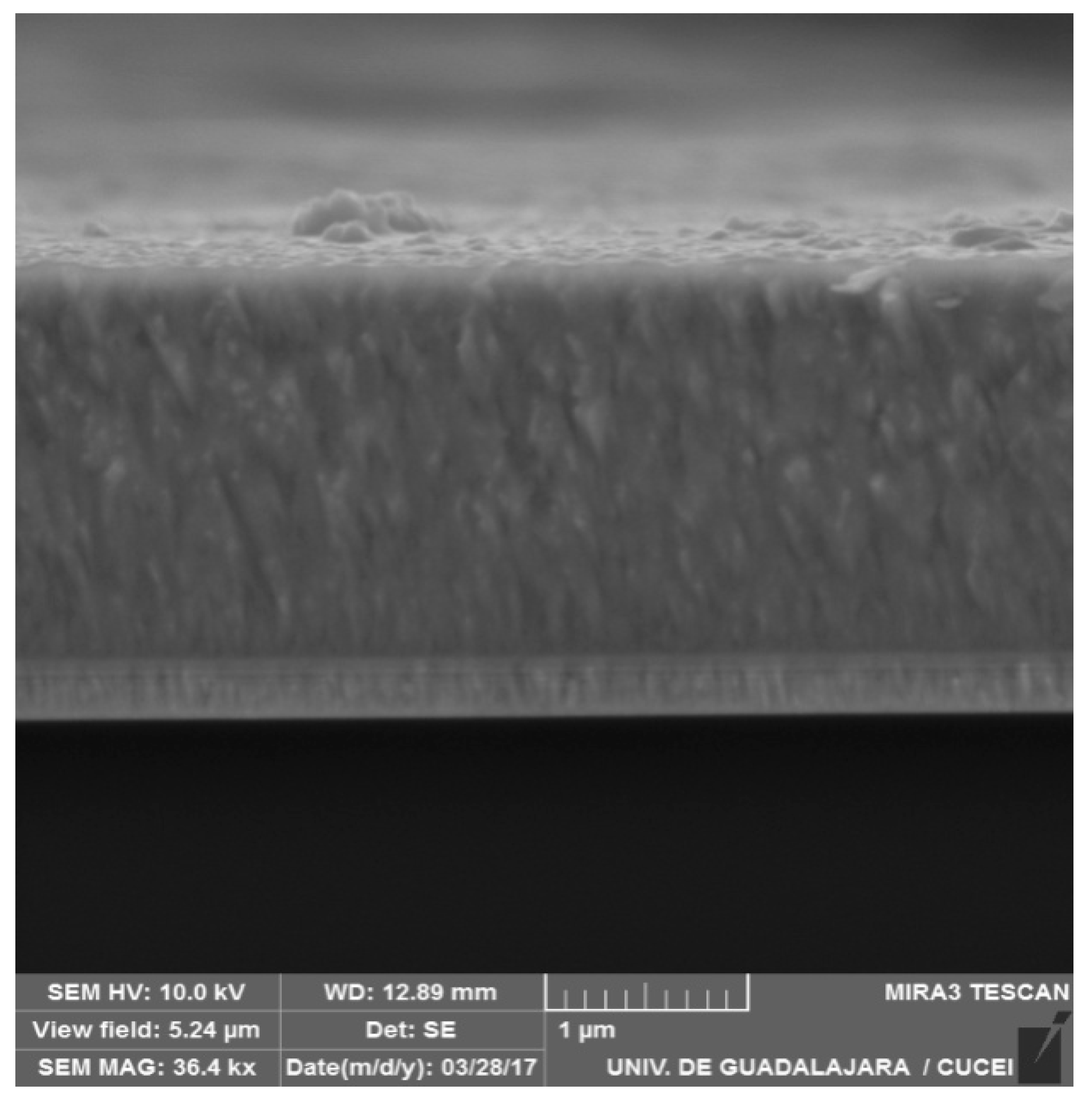
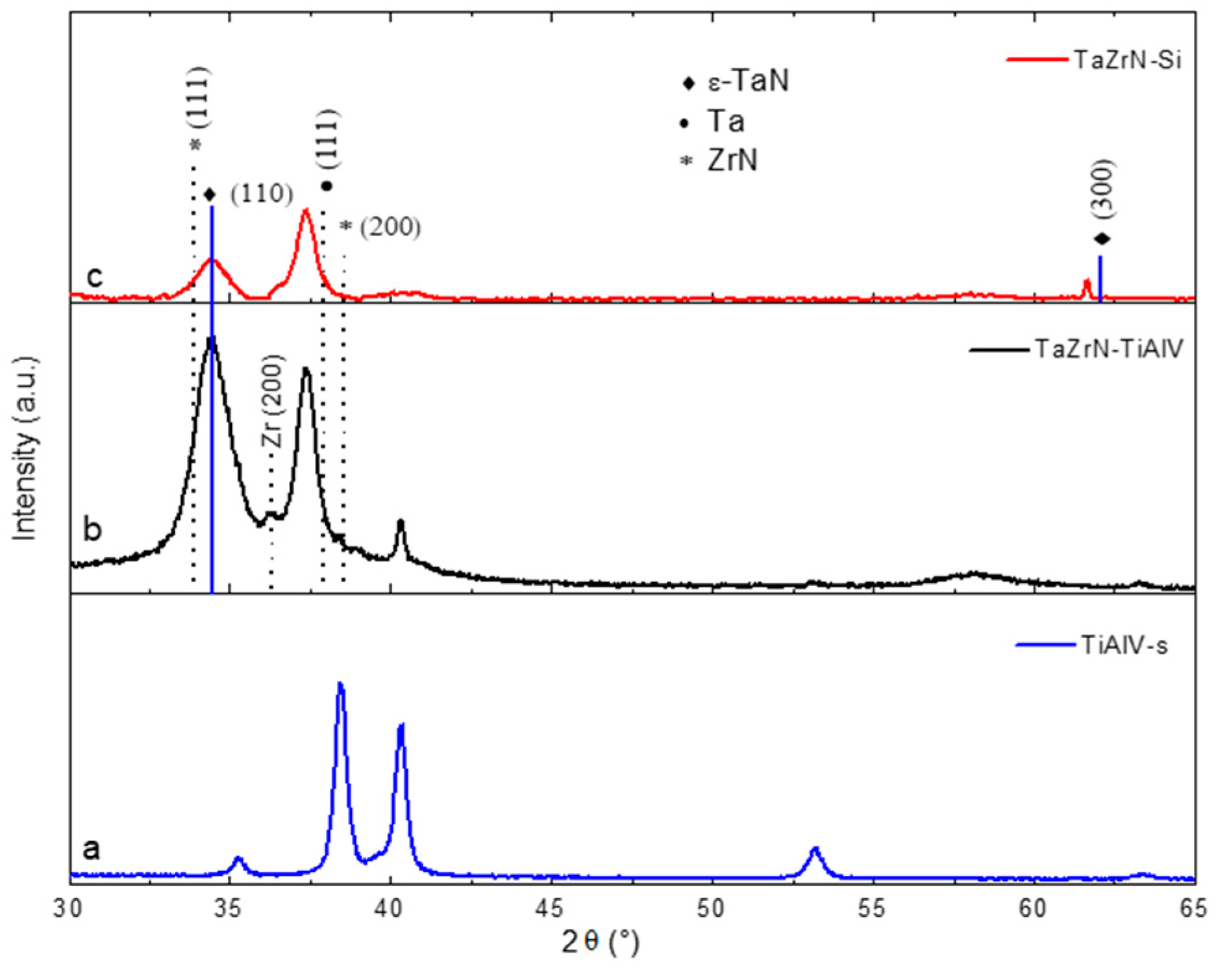
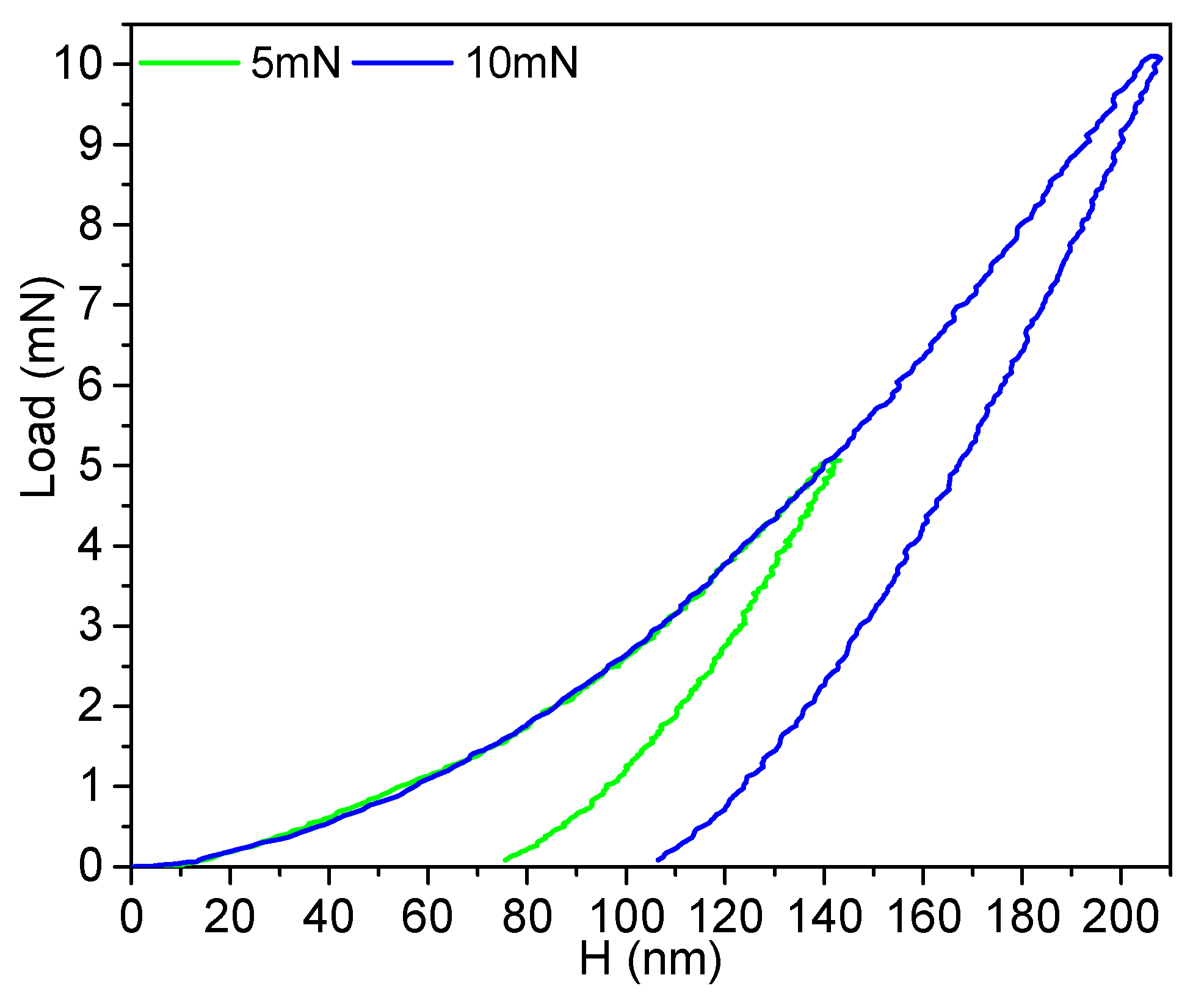
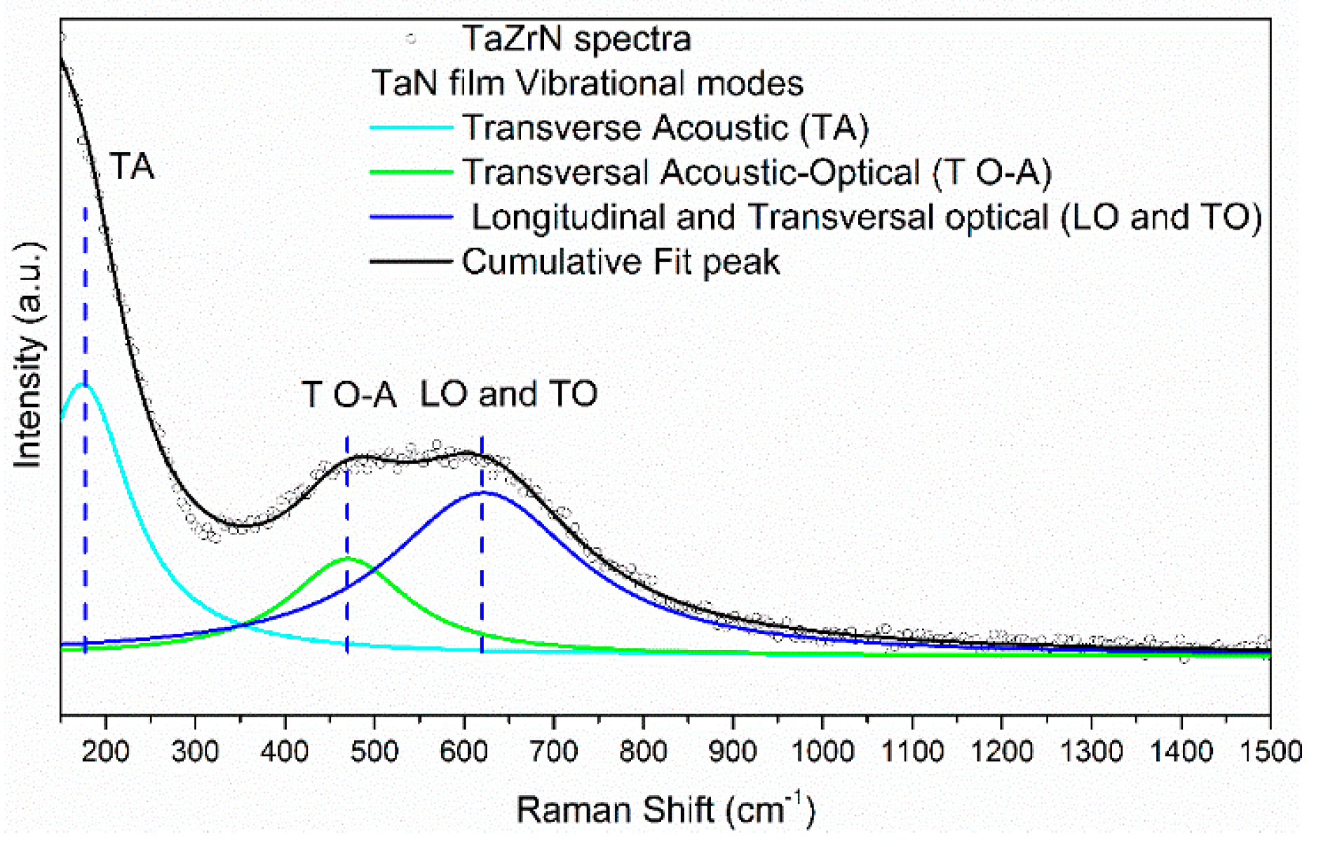
3.1. Characterization of Films (SEM, XRD, Raman, and Corrosion Studies)

Figure 1 shows a cross section of the film deposited on a Si substrate. The layer consisted of two layers: the first of metallic TaZr film with a thickness of ~200 nm that was deposited to improve the adhesion of the TaZrN coating to the metallic substrate, and the second of TaZrN. The deposition rate of the nitride layer, measured from SEM images on the Si substrate, was ~18 nm/min, similar to that reported in [9,19,20] for TaN films with similar N2 flow ratios of 15% (N2/(N2 + Ar)).
The X-ray diffractograms of the layers deposited on Si and metallic substrates are shown in Figure 2. The diffractogram shows peaks corresponding to hexagonal ε-TaN and one to the metallic cubic Ta phase [9,19,20,21,22,23,24,25,26]. The preferred orientation for ε-TaN is (110) for both substrates; for the Si substrate there is a peak corresponding to direction (300). The most intense diffraction peak of the coating on the Si substrate is near the orientation (111) of Ta, while on the Ti alloy substrates the strongest peak was from the orientation (110) of ε-TaN. From the coating on metallic substrate we observed small peaks around 36.27° and 38.41° [27,28,29] that can be associated with Zr (200) and ZrN (200), respectively. The peak at 2θ 34.4 is to the right to orientation (111) of ZrN and could be associated with this phase, but typically the compressive stresses in hard coating deposited by sputtering produce a shift toward smaller angles with respect to the original position of diffraction peaks; in this case, the situation is the opposite. Was not possible to differentiate the peaks from Zr and ZrN respect to such from Ta and TaN; because they are in similar positions and are overlapping [12,16].
The measured nanohardness (H) at 5 and 10 mN (Figure 3) was 18.9 ± 1.485 mN and 19.7 ± 1.810 mN GPa, respectively (the penetration depth at 10 mN was less than 15% of the thickness of the layer); this value is within the range (11 to 31 GPa) reported in the literature [12,26,30,31,32,33]. The elastic modulus was 189 GPa using 10 mN and 203 ± 12.9 using 5 mN, somewhat lower than that reported for TaZrN [12,27,30] and TaN [26,32,33,34,35,36] films, as an effect of the Zr concentration in the TaN film [11,30,31,34]. The Ra roughness of the films deposited on TiAlV was 87.7 ± 3.5 nm. The H/E ratio was 0.104, indicating that the layers should have a high resistance to plastic deformation and good wear resistance [37]. The semi-quantitative composition (at.%) obtained by the EDS technique was Ta = 18 ± 0.5, Zr = 13.8 ± 0.3, N = 60 ± 0.1, and O = 8.2 ± 0.3.
Figure 4 shows the Raman spectra of the as-deposited TaZrN and the deconvolution of the three main bands. The bands around 175 and 470 cm−1 correspond to the LA and TA, attributed to longitudinal and transversal acoustic vibrations of the heavy ions (typically of metal ions), while the band around 620 cm−1 is from the LO and TO optical vibrational modes of the lighter ions (nitrogen ions) [31,38,39,40,41,42].
Figure 5 shows the potentiodynamic polarization curves of the TaZrN film and the TiAlV substrate. The curves of coated and uncoated samples are similar in the cathodic zone. The corrosion potential (Ecorr) of the film was −160 mV and for the substrate −200 mV; as a consequence, the coated sample showed a lower thermodynamic tendency to be corroded.
The corrosion current density was calculated by Tafel extrapolation using the region of the curves near the corrosion potential, resulting in 1.4 × 10⁻⁸ A/cm2 for substrate and 1.32 × 10⁻⁸ A/cm2 for the sample coated with TaZrN. In the beginning of the anodic zone the TaZrN film had a current density slightly lower than the substrate, but when the coated sample became more active and the corrosion current density was higher than the substrate this change started at −120 mV and the behavior remained for high anodic potentials.
The curve of the coated sample showed an increase in the current density at a potential of 220 mV and then had fast passivation; this behavior might be due to the presence of pinholes or defects in the coating that permit the electrolyte to reach the substrate and start a localized corrosion at this point, but the titanium alloy Ti6Al4V is very resistant to pitting corrosion, showing quick passivation [10,13,14].

3.2. Tribological Studies in Dry and Corrosive Conditions

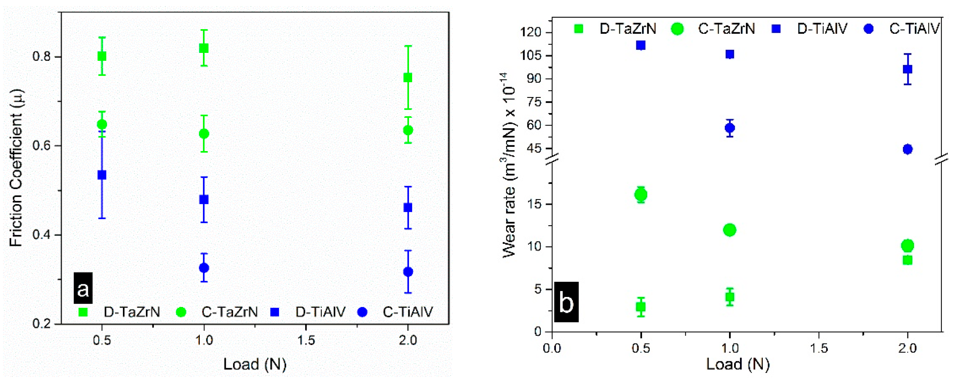
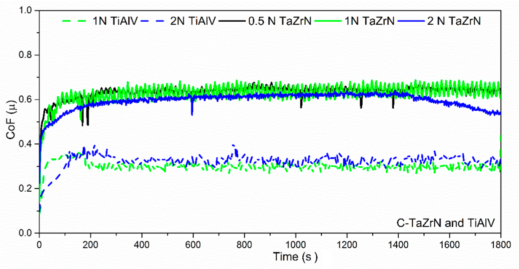
3.2.1 Friction and Wear

Figure 6a shows the average coefficient of friction (COF) measured during the sliding test for dry (D) and corrosive (C) conditions. It can be appreciated that the values obtained from the tests on the uncoated surfaces are lower for both conditions, with a higher value for the dry conditions. The COF for the coated surfaces was stable as a function of the load, with values of 0.8 and 0.62 for the dry and corrosive conditions, respectively. The values of COF for the coated surfaces were higher than the substrate; values of friction coefficient between 0.6 and 0.8 are typical for nitride coatings using an Al2O3 ball as counterpart [42]. The reduction of the COF for the wet tests with respect to dry conditions for coatings and substrates was due principally to the removal of the tribolayer formed at dry conditions, as can be seen in the figures with SEM and optical images (see figures for dry, and wet tests). Moreover, the SBF solution acts as a lubricant between the ball and the sample.
Figure 6b shows the changes in the wear rate as a function of the applied load. These results show that the TaZrN coating had a lower wear rate than TiAlV for dry and corrosive situations, in the case of dry conditions, and for a load of 0.5 N the reduction was about 50 times. However, this was different for the TiAlV alloy, where the wear rate value was larger in dry conditions than in corrosive liquid; the wear rate exhibited by the coated surfaces suffers more in a corrosive environment than in dry conditions. This could be because during the tests at dry conditions the wear tracks of coatings were covered with a tribolayer of transferred material during the sliding that protects the surfaces, while during tests in a corrosive environment this material was not generated or was removed by the corrosive action of the liquid. This will be discussed in the next section, using the Raman results. It is noticeable that some values of the coating wear coefficient have a very low standard deviation for tribocorrosion tests at 2 N loads. For coated samples the low loss of volume results in error bars similar in size to the circles and squares using to make the graphic.
Figure 7a shows the profiles of the wear track on the coated surfaces. In the profile of 0.5 N we observed that the wear created at this load just changed the surface aspirates, producing minor damage on the surfaces. For the load of 1 N the damage was increased but remained low. Although the test at 2 N has greater depth, the track depth was not longer than the layer thickness and therefore remained, protecting the metallic substrate from wear. Figure 7b shows the profiles of coated and uncoated samples tested with a load of 1 N; the reduction in the width and depth of the wear track is evident.

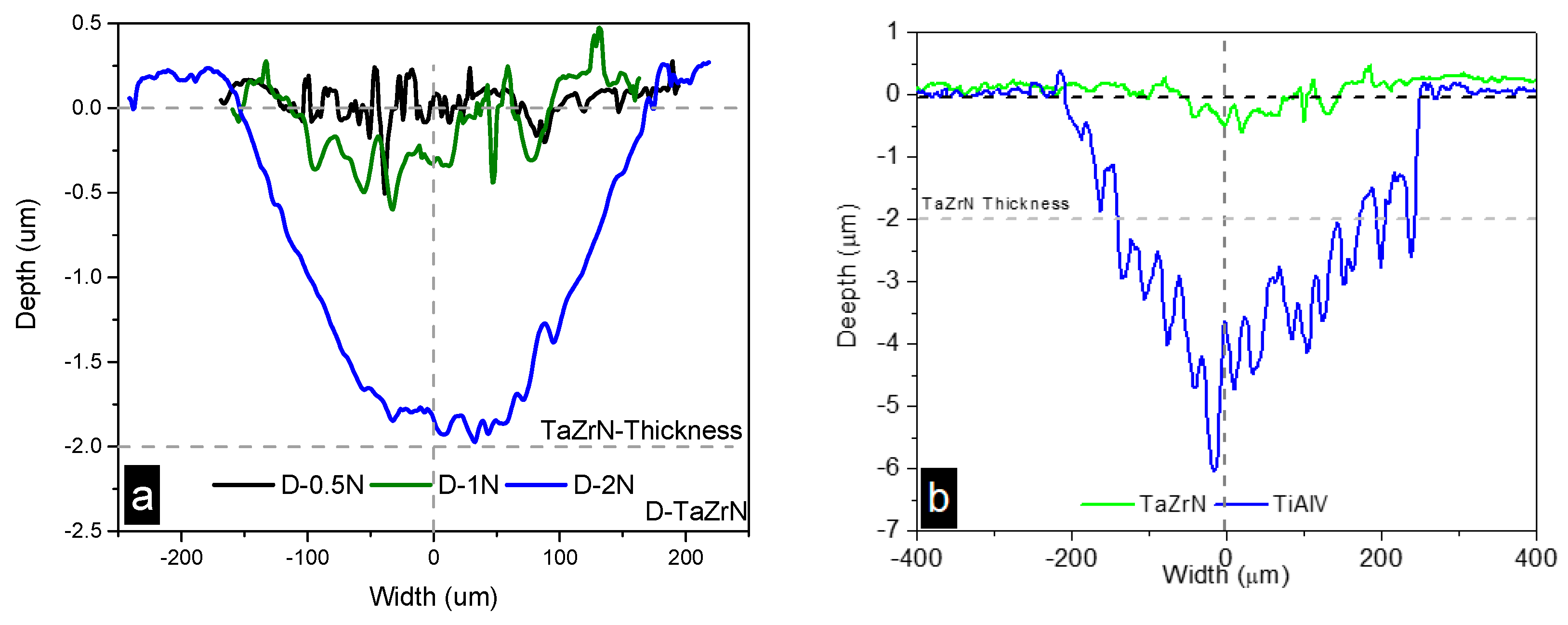
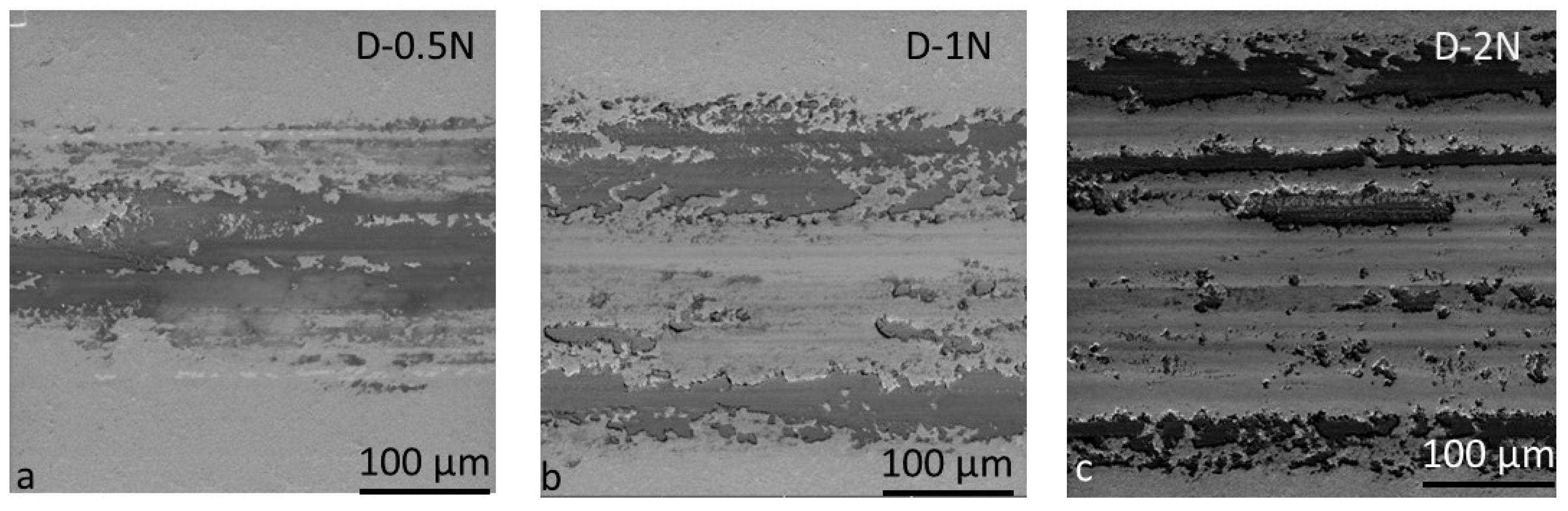
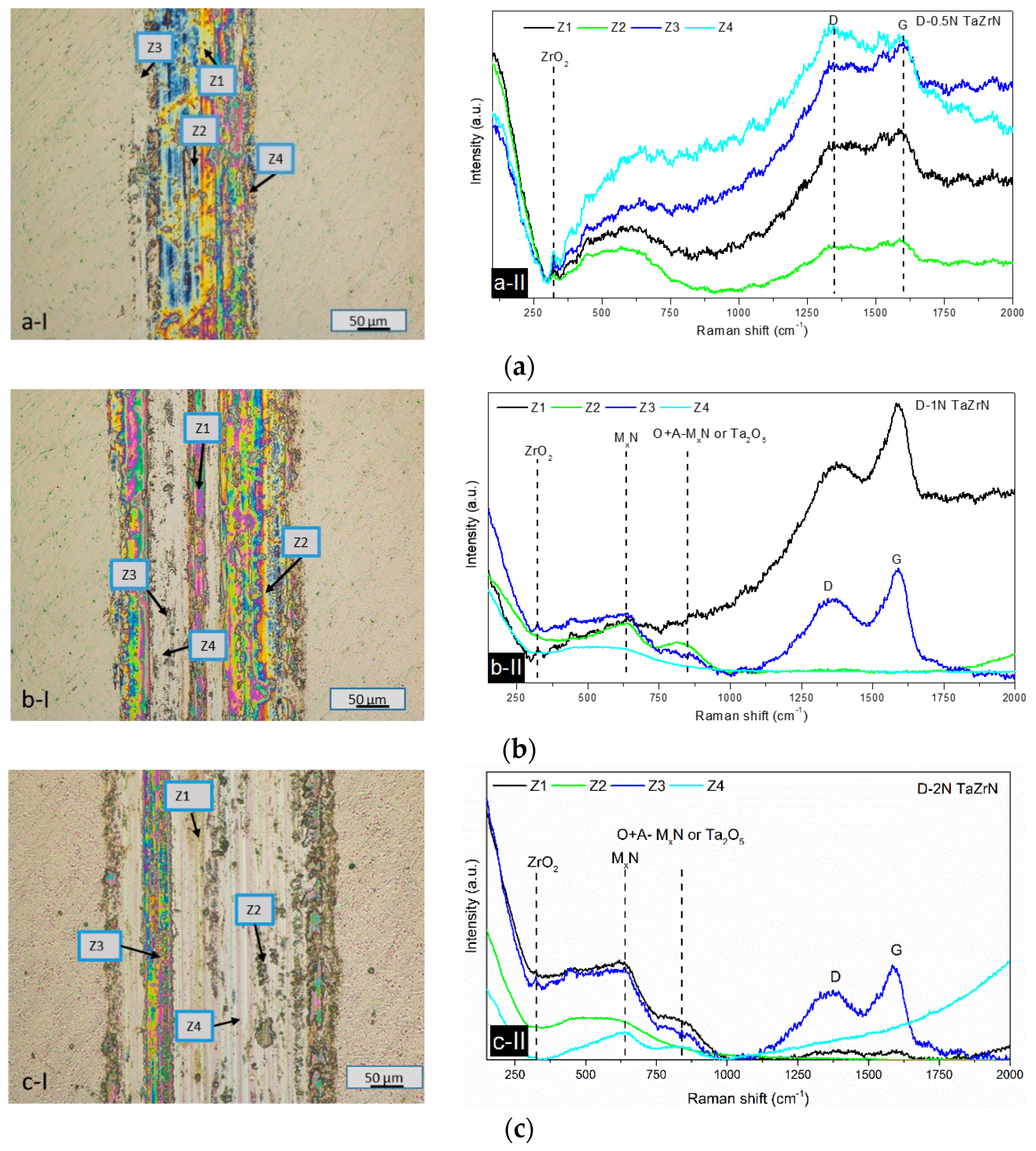
3.2.2. Wear Mechanism Analysis at Dry Conditions

Figure 8a is the SEM image of the wear track produced in the dry test at a load of 0.5 N. In this image we observe that the main wear mechanism was adhesive with transferred material that was adhered in the wear track and small scratches due to abrasion on the edges of the track and on the tribolayer at its center.
The tribolayer that covers almost all the track surface acts as a third-body separating the sample from the ball and reduces the wear rate with respect to the substrate by dozens of times.
The Raman analyses indicate that this tribolayer contains zirconium oxide, amorphous carbon, and graphite (see Figure 9). The SEM image of the wear track produced at 1 N (see Figure 8b) exhibited a combination of the same adhesive wear mechanism as that at 0.5 N with material accumulated on the track borders and the appearance of abrasion grooves in the center of the wear track [43], but some compact tribolayer still survives in the form of continuous bands. The wear track generated at 2 N shows the removal of the tribolayer, producing discontinuous tribolayer bands accumulated in the border and the center of the track and an increase in the number and size of grooves produced by the hard asperities ploughing, which indicate a transition from adhesive to abrasive wear mechanism, as can be seen in Figure 8c.
Figure 9 shows the wear tracks of optical images and the Raman spectra of the different zones that were divided for the study of the coated samples at 0.5, 1, and 2 N in dry conditions.
The wear track area produced at 0.5 N was analyzed in zones (see Figure 9(a-I), and studied by Raman spectroscopy (see Figure 9(a-II)). The Raman spectrum has bands around 1350 and 1600 cm−1 that indicate the presence of amorphous carbon [44,45,46] and graphite. The position and broadening of the peaks indicate that they were generated by graphite and amorphous carbon [47]. The formation of a graphite layer has been reported in the literature for metal-on-metal hip implants, MEMS (Micro-Electro-Mechanical Systems) gears, and industrial machines; all are lubricated with organic molecules. Through friction, wear, and catalysis at the metal interface, the organic material reacts to form carbon films similar to ordered or disordered graphitic films [48,49]. On the other hand, there are observations of graphite formation in the transferred material in wear tracks obtained at atmospheric conditions, using as counterparts WC/WCN/W hierarchical multilayer and an alumina ball; in that experiment the carbon comes from the WC layer [50]. However, in this case the surface of TaZrN without rubbing does not show the content of amorphous carbon in the Raman analysis (see Figure 4); the worn samples were cleaned at ultrasonic bath before the test, and the tests at dry conditions was carried out without lubrication of organic molecules. Therefore, it is possible to speculate that carbon films in tribolayer could be produced by the CO2 in the atmosphere. There is a peak similar to ZrO around 325 cm−1 [51,52]. The Raman analysis of the wear track area produced by the test at 1 N was divided into four zones (see Figure 9(b-I)) and the resulting spectra exhibit bands similar to graphite, as can be seen in Figure 9(b-II). As is well known, graphite is a solid lubricant that can reduce the friction and protect the material from wear, but in this case the friction coefficient was around 0.8. The amorphous carbon bands were observed in Zone 1, besides the small peak at 325 cm−1 associated with ZrO. Zone 2 presented bands around 620 cm−1, associated with nitride metal, and 850 cm−1, which could be formed with the Acoustic + Optical Raman mode of the nitride layer [38] that arises from structural deformation near surfaces or from the tantalum oxide [53,54]. Figure 9(c-I) shows the zones used to obtain the Raman study of the wear track at 2 N; the resulting spectra are shown in Figure 9(c-II). The spectra were similar that those of 0.5 and 1 N, except in Zone 4 with big grooves where the bands centered at 200 and 550 cm−1 were smaller than in the other zones and the peaks of carbon films disappear.

3.3. Tribological and Corrosion Studies in Corrosive Media

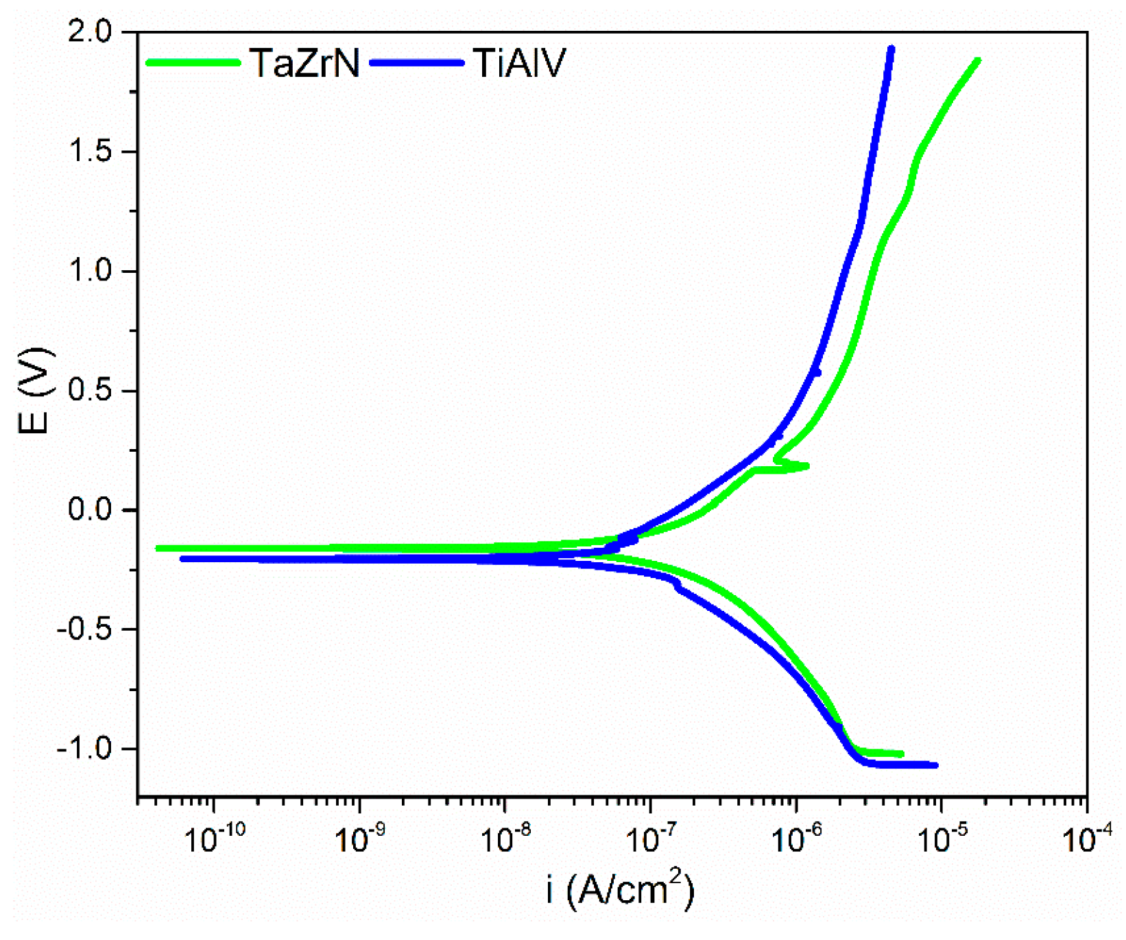
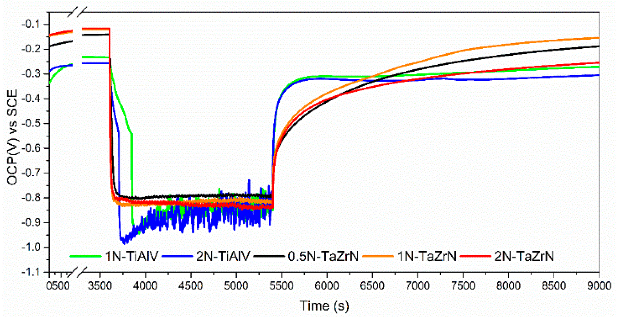
3.3.1. Friction, Tribocorrosion, and Corrosion Results

Figure 10 shows the measured coefficient of friction (COF) during the sliding period in the tribocorrosion tests. The evolution of the COF during the test was stable except at 2 N; at about 1400 s the COF begins to decrease, a change that can be attributed to the pin touching the substrate.
The values of COF were lower than in dry conditions as a result of the lubricating effect of saline solution. As is presented in Figure 6b, the resulting wear volume at corrosive conditions was higher than that produced in dry conditions. This difference can be attributed to the synergistic effect of corrosion on wear and vice versa, and the absence of protective film in the wear products [55,56]. The wear track produced in the tribocorrosive test shows a smooth form that was produced by the corrosive wear mechanism, with small quantities of transferring material on the track borders. Figure 11 shows profiles of the wear track produced at 0.5, 1, and 2 N. These profiles presented a smoother surface than in the dry tests in the wear track zones.
Figure 12 shows the OCP measurements during the tribocorrosion tests at 0.5, 1, and 2 N (before, during, and after the sliding test) on the TaZrN film and at 1 N and 2 N for TiAlV substrate. The OCP of TiAlV substrates was from around −0.250 mV; meanwhile, the coated samples show a potential between −150 and −125 mV, with the less negative potential indicating a lower tendency of the coated samples to be corroded. When the sliding starts the potential falls abruptly to a value between −0.83 V and −0.8 V for the coated samples and between −0.98 V and −0.93 V for the substrate; for each group the highest drop is for the highest load, with this difference between the potential for coated samples and substrates indicating that the coating remains, protecting the substrate. The potential value for coated samples was stable, while for the substrates it oscillates from 400 s until to the sliding contact finishes. When the contact and sliding motion stop, the potential increases abruptly, indicating a repassivation of the surface; the recovery of the potential is faster for substrates than for coated samples, but by the end the recovery time the coated samples reach a more positive value except for the test at 2 N. In this case the coating was delaminated and the substrate was exposed to the electrolyte, as can be seen in Figure 13c. The OCP value for TaZrN/TiAlV in SBF solution was slightly more positive than the potential reported in reference [57] for TaN/Ti-cp corroded in a phosphate-buffered solution (PBS) plus 1 g of albumin, they used a rotation speed of 100 rpm, load of 3 N, and a ball-on-disk tribometer.

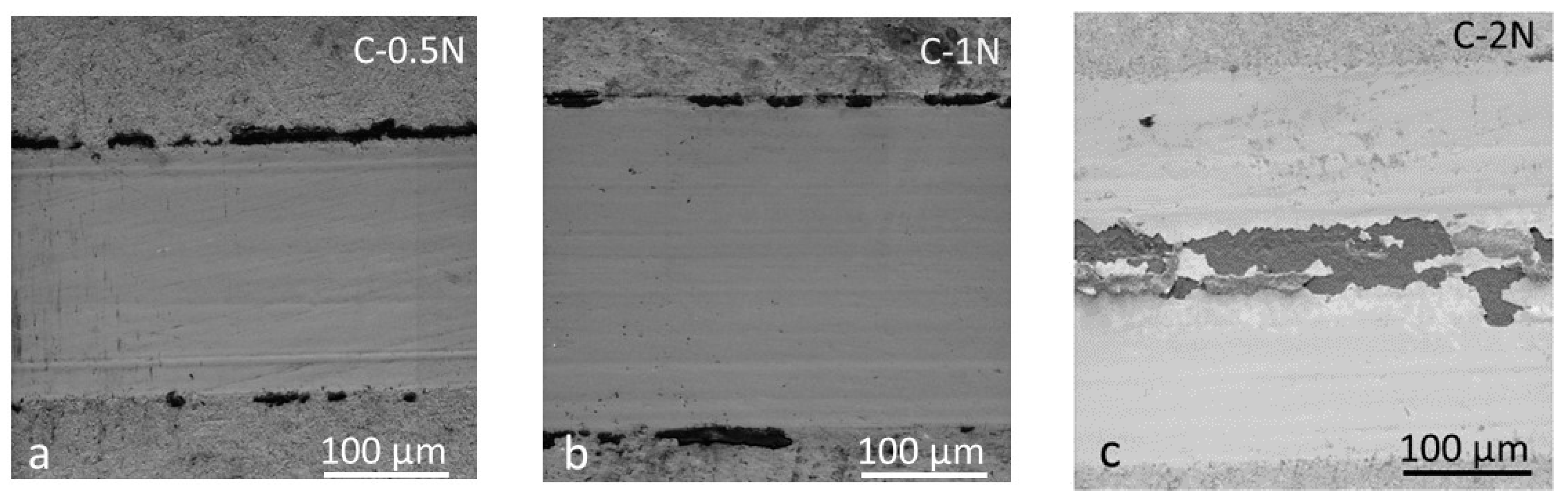
3.3.2. Wear Mechanisms in Wet Conditions

Figure 13 shows SEM images of the wear tracks obtained at 0.5, 1, and 2 N. We observed small plowing marks in the wear track center of tests carried out at 0.5 and 1 N and in the image of 2 N we observed the loss of the layer in the center of the wear track. The electrolyte permeates through the defects of the coating; the corrosion attacks the substrate-coating interface and the coating is delaminated. The principal wear mechanism for wet conditions is wear–corrosion instead of abrasive wear that was observed for dry conditions.
In the same way, the optical images presented smooth surfaces without different color tonalities (see Figure 14(a-I–c-I)). The Raman studies of the wear track produced at 0.5 and 1 N presented a band around 850 cm−1 and a decrement of the bands at 175 and 475 cm−1 [38] (see Figure 14(a-II,b-II)). The spectra obtained in Zone 4 on the wear track at 1 N could be produced for the SBF material accumulated on the side of the track. Figure 14(c-II) shows the Raman spectra obtained from the 2 N track; while the spectra from Zone 2 were similar to the layer without damage, Zones 1 and 3 present the substrate spectra plus fluorescence and the D and G band of carbon layers. The Z1 spectra could be produced by the accumulation of SBF salts.

4. Discussion

Ternary TaZrN films were deposited on Si (111) and TiAlV alloy substrates by means of co-sputtering of targets of Ta and Zr. Although the produced coating presented the same structure and orientation for both substrates, the substrate influence generated different preferential growth orientation and in consequence the intensity in the diffraction peak of the plane (110) of Ta changes from the second to the first position when the layers are deposited on TiAl and Si, respectively. The hardness and elastic modulus were measured using nanoindentation and we found a similar hardness value to a reported TaN film but with a lower elastic modulus This produced a value near 0.1 in the relation H/E, which could indicate a high resistance to plastic deformation because it is associated with good wear resistance [12,36,37,58].
The coefficient of friction produced during the sliding tests on the TaZrN layer was greater than on the TiAlV substrate, with a COF value around 0.8 and 0.62 in dry and wet conditions, respectively; ceramic coatings typically have higher COF compared with metallic substrates. The TaZrN coating produced good wear protection of the metallic substrate in dry conditions, which can be attributed to the mechanical properties of the coating and to the oxide and carbon layers produced during the sliding. The position of the bands in the Raman shift permits us to suppose that there is graphite and amorphous carbon, which are beneficial for lubrication and protection against wear, but the COF does not show a reduction for the tracks with a compact tribolayer where there is an influence of the oxide layers. When the load is increased, the protective tribolayer diminishes, the wear mechanism becomes abrasive, and the wear rate is increased. The wear rate of the coated surfaces was higher in corrosive than in dry conditions; SEM and optical microscopy images show that in corrosive media the tribolayer almost disappears, as confirmed by Raman spectroscopy. For the load of 2 N the wear tracks in dry and wet conditions of the tribolayer are only in a few zones, so the wear rate is similar for both conditions, but is lower for dry than corrosive ambient; for this load the coating is delaminated in corrosive media and the abrasive–corrosive wear mechanism is the principal cause of damage. The synergistic effect of corrosion on the wear can also produce an increase in the wear rate for the corrosion conditions with respect to the dry tests carried out at a relative humidity of 31%. The corrosion results indicate a similar current corrosion, but after the corrosion potential for more anodic potentials the current of coated samples was higher than the substrates.
The measured potential in SBF liquid for the TaZrN coating during the tribocorrosion test showed more stable behavior and was less negative than the TiAlV substrate, indicating a lower tendency to be corroded.

5. Conclusions

Hard coatings of TaZrN were deposited by sputtering and its tribological behavior was studied by sliding reciprocating tests. It was found that the corrosive effect of SBF increases the wear rate with respect to dry tests. The analysis of the wear tracks by confocal Raman spectroscopy and SEM images was a powerful tool to understand the wear mechanism. The wear mechanism shows a transition when the load is increased becoming abrasive for a load of 2 N. Some zones of the wear tracks have formed from oxides and carbon layers of graphite and amorphous carbon. The formation of a beneficial graphite tribolayer could be promoted by the design of the coating surfaces. Tribocorrosion tests were carried out on the biomedical alloy Ti6Al4V coated with TaZrN. Therefore, it is expected that the reduction in wear rate found in the laboratory conditions can increase the useful life of implantable devices made with this material.

Author Contributions

Conceptualization, E.G. and M.F.; Investigation, E.G., E.R., S.M., L.P.R. and E.C.; Writing–Original Draft Preparation, E.G., L.P.R.; Writing–Review & Editing, E.G. and M.F.; Funding Acquisition, M.F.

Funding

This research was funded by CONACYT programs Frontiers of Science (Project 1103), Thematic Networks (Project 295462).

Acknowledgments

E. Garcia acknowledges Cátedras-CONACYT for professorship 2251. This work and the publication cost were supported by the University of Guadalajara.

Conflicts of Interest

The authors declare no conflict of interest.

References

  1. Inspektor, A.; Salvador, P.A. Architecture of PVD coatings for metalcutting applications: A review. Surf. Coat. Technol. 2014, 257, 138–153. [Google Scholar] [CrossRef]
  2. Bemporad, E.; Pecchio, C.; De Rossi, S.; Carassiti, F. Characterization and hardness modelling of alternate tin/ticn multilayer cathodic arc PVD coating on tool steel. Surf. Coat. Technol. 2001, 146, 363–370. [Google Scholar] [CrossRef]
  3. Gautier, C.; Moussaoui, H.; Elstner, F.; Machet, J. Comparative study of mechanical and structural properties of CrN films deposited by DC Magnetron sputtering and vacuum arc evaporation. Surf. Coat. Technol. 1996, 86–87, 254–262. [Google Scholar] [CrossRef]
  4. Ma, K.; Chao, C.; Liu, D.; Chen, Y.; Shieh, M.B. Friction and wear behaviour of TiN/Au, TiN/MoS2 and TiN/TiCN/a-C:H coatings. J. Mater. Process. Technol. 2002, 127, 182–186. [Google Scholar] [CrossRef]
  5. Chhowalla, M.; Unalan, H.E. Thin films of hard cubic Zr3N4 stabilized by stress. Nat. Mater. 2005, 4, 317–322. [Google Scholar] [CrossRef] [PubMed]
  6. Jehn, H.A. Multicomponent and multiphase hard coatings for tribological applications. Surf. Coat. Technol. 2000, 131, 433–440. [Google Scholar] [CrossRef]
  7. Jozwik, J. Evaluation of tribological properties and condition of Ti6Al4V titanium alloy surface. Tech. Gazette 2018, 25, 170–175. [Google Scholar]
  8. Münz, W.D. Titanium aluminum nitride films: A new alternative to tin coatings. J. Vac. Sci. Technol. A 1986, 4, 2717–2725. [Google Scholar] [CrossRef]
  9. Sun, X.; Kolawa, E.; Chen, J.-S.; Reid, J.S.; Nicolet, M.-A. Properties of reactively sputter-deposited TaN thin films. Thin Solid Films 1993, 236, 347–351. [Google Scholar] [CrossRef]
  10. Alishahi, M.; Mahboubi, F.; Mousavi Khoie, S.M.; Aparicio, M.; Lopez-Elvira, E.; Mendez, J.; Gago, R. Structural properties and corrosion resistance of tantalum nitride coatings produced by reactive DC magnetron sputtering. RSC Adv. 2016, 6, 89061–89072. [Google Scholar] [CrossRef]
  11. Lee, G.; Kim, H.; Choi, H.; Lee, J. Superhard tantalum-nitride films formed by inductively coupled plasma-assisted sputtering. Surf. Coat. Technol. 2007, 201, 5207–5210. [Google Scholar] [CrossRef]
  12. Aouadi, S.M. Structural and mechanical properties of tazrn films: Experimental and ab initio studies. J. Appl. Phys. 2006, 99, 053507. [Google Scholar] [CrossRef]
  13. Yildiz, F.; Yetim, A.F.; Alsaran, A.; Çelik, A. Plasma nitriding behavior of Ti6Al4V orthopedic alloy. Surf. Coat. Technol. 2008, 202, 2471–2476. [Google Scholar] [CrossRef]
  14. Yetim, A.F.; Alsaran, A.; Efeoglu, I.; Çelik, A. A comparative study: The effect of surface treatments on the tribological properties of Ti–6Al–4V alloy. Surf. Coat. Technol. 2008, 202, 2428–2432. [Google Scholar] [CrossRef]
  15. Benea, L.; Wenger, F.; Ponthiaux, P.; Celis, J.P. Tribocorrosion behaviour of Ni–SiC nano-structured composite coatings obtained by electrodeposition. Wear 2009, 266, 398–405. [Google Scholar] [CrossRef]
  16. Azzi, M.; Paquette, M.; Szpunar, J.A.; Klemberg-Sapieha, J.E.; Martinu, L. Tribocorrosion behaviour of DLC-coated 316l stainless steel. Wear 2009, 267, 860–866. [Google Scholar] [CrossRef]
  17. Probst, J.; Gbureck, U.; Thull, R. Binary nitride and oxynitride PVD coatings on titanium for biomedical applications. Surf. Coat. Technol. 2001, 148, 226–233. [Google Scholar] [CrossRef]
  18. Kokubo, T.; Takadama, H. How useful is SBF in predicting in vivo bone bioactivity? Biomaterials 2006, 27, 2907–2915. [Google Scholar] [CrossRef] [PubMed]
  19. Noda, S.; Tepsanongsuk, K.; Tsuji, Y.; Kajikawa, Y.; Ogawa, Y.; Komiyama, H. Preferred orientation and film structure of TaN films deposited by reactive magnetron sputtering. J. Vac. Sci. Technol. A Vac. 2004, 22, 332–338. [Google Scholar] [CrossRef]
  20. Chang, C.-C.; Jeng, J.S.; Chen, J.S. Microstructural and electrical characteristics of reactively sputtered Ta–N thin films. Thin Solid Films 2002, 413, 46–51. [Google Scholar] [CrossRef]
  21. Shen, H.; Ramanathan, R. Fabrication of a low resistivity tantalum nitride thin film. Microelectron. Eng. 2006, 83, 206–212. [Google Scholar] [CrossRef]
  22. Radhakrishnan, K.; Geok Ing, N.; Gopalakrishnan, R. Reactive sputter deposition and characterization of tantalum nitride thin films. Mater. Sci. Eng. B 1999, 57, 224–227. [Google Scholar] [CrossRef]
  23. Tsukimoto, S.; Moriyama, M.; Murakami, M. Microstructure of amorphous tantalum nitride thin films. Thin Solid Films 2004, 460, 222–226. [Google Scholar] [CrossRef]
  24. Lee, W.-H.; Lin, J.-C.; Lee, C. Characterization of tantalum nitride films deposited by reactive sputtering of Ta in N2/Ar gas mixtures. Mater. Chem. Phys. 2001, 68, 266–271. [Google Scholar] [CrossRef]
  25. Nie, H.; Xu, S.; Wang, S.; You, L.; Yang, Z.; Ong, C.K.; Li, J.; Liew, T.Y.F. Structural and electrical properties of tantalum nitride thin films fabricated by using reactive radio-frequency magnetron sputtering. Appl. Phys. A 2001, 73, 229–236. [Google Scholar] [CrossRef] [Green Version]
  26. Kim, S.K.; Cha, B.C. Deposition of tantalum nitride thin films by DC Magnetron sputtering. Thin Solid Films 2005, 475, 202–207. [Google Scholar] [CrossRef]
  27. Abadias, G. Stress and preferred orientation in nitride-based PVD coatings. Surf. Coat. Technol. 2008, 202, 2223–2235. [Google Scholar] [CrossRef]
  28. Linder, C.; Dommann, A.; Staufert, G.; Nicolet, M.A. Ternary Ta–Si–N films for sensors and actuators. Sens. Actuators A Phys. 1997, 61, 387–391. [Google Scholar] [CrossRef]
  29. Sandu, C.S.; Sanjinés, R.; Benkahoul, M.; Medjani, F.; Lévy, F. Formation of composite ternary nitride thin films by magnetron sputtering co-deposition. Surf. Coat. Technol. 2006, 201, 4083–4089. [Google Scholar] [CrossRef]
  30. Abadias, G.; Kanoun, M.B.; Goumri-Said, S.; Koutsokeras, L.; Dub, S.N.; Djemia, P. Electronic structure and mechanical properties of ternary ZrTaN alloys studied by ab initio calculations and thin-film growth experiments. Phys. Rev. B 2014, 90, 144107. [Google Scholar] [CrossRef]
  31. Valleti, K. Studies on hard tan thin film deposition by R C-Mag technique. J. Vac. Sci. Technol. A 2009, 27, 626–630. [Google Scholar] [CrossRef]
  32. Kang, Y.; Lee, C.; Lee, J. Effects of processing variables on the mechanical properties of Ta/TaN multilayer coatings. Mater. Sci. Eng. B 2000, 75, 17–23. [Google Scholar] [CrossRef]
  33. Kim, D.-k.; Lee, H.; Kim, D.; Keun Kim, Y. Electrical and mechanical properties of tantalum nitride thin films deposited by reactive sputtering. J. Cryst. Growth 2005, 283, 404–408. [Google Scholar] [CrossRef]
  34. Mody, N.R.; Hwang, R.Q.; Venka-taraman, S.; Angelo, J.E.; Norwood, D.P.; Gerberich, W.W. Adhesion and fracture of tantalum nitride films. Acta Mater. 1998, 46, 585–597. [Google Scholar] [CrossRef]
  35. Westergård, R.; Bromark, M.; Larsson, M.; Hedenqvist, P.; Hogmark, S. Mechanical and tribological characterization of DC magnetron sputtered tantalum nitride thin films. Surf. Coat. Technol. 1997, 97, 779–784. [Google Scholar] [CrossRef]
  36. Musil, J. Hard nanocomposite coatings: Thermal stability, oxidation resistance and toughness. Surf. Coat. Technol. 2012, 207, 50–65. [Google Scholar] [CrossRef]
  37. Leyland, A.; Matthews, A. On the significance of the H/E ratio in wear control: A nanocomposite coating approach to optimised tribological behaviour. Wear 2000, 246, 1–11. [Google Scholar] [CrossRef]
  38. Constable, C.P.; Yarwood, J.; Münz, W.D. Raman microscopic studies of PVD hard coatings. Surf. Coat. Technol. 1999, 116–119, 155–159. [Google Scholar] [CrossRef]
  39. Constable, C.P.; Lewis, D.B.; Yarwood, J.; Münz, W.D. Raman microscopic studies of residual and applied stress in PVD hard ceramic coatings and correlation with X-ray diffraction (XRD) measurements. Surf. Coat. Technol. 2004, 184, 291–297. [Google Scholar] [CrossRef]
  40. Blanpain, B.; Franck, M.; Mohrbacher, H.; Vancoille, E.; Celis, J.P.; Roos, J.R. Micro-Raman spectroscopy for the characterization of wear induced surface modifications on hard coatings. Tribol. Ser. 1993, 25, 623–630. [Google Scholar]
  41. Jallad, K.N.; Ben-Amotz, D. Raman chemical imaging of tribological nitride coated (TiN, TiAlN) surfaces. Wear 2002, 252, 956–969. [Google Scholar] [CrossRef]
  42. Biswas, S.K.; Arvind Singh, R. Wear of metals—Influence of some primary material properties. Tribol. Lett. 2002, 13, 203–207. [Google Scholar] [CrossRef]
  43. Holmberg, K.; Ronkainen, H.; Matthews, A. Tribology of thin coatings. Ceram. Int. 2000, 26, 787–795. [Google Scholar] [CrossRef]
  44. Sánchez-López, J.C.; Martínez-Martínez, D.; Abad, M.D.; Fernández, A. Metal carbide/amorphous C-based nanocomposite coatings for tribological applications. Surf. Coat. Technol. 2009, 204, 947–954. [Google Scholar] [CrossRef] [Green Version]
  45. Aouadi, S.M.; Luster, B.; Kohli, P.; Muratore, C.; Voevodin, A.A. Progress in the development of adaptive nitride-based coatings for high temperature tribological applications. Surf. Coat. Technol. 2009, 204, 962–968. [Google Scholar] [CrossRef]
  46. Neuhaeuser, M.; Hilgers, H.; Joeris, P.; White, R.; Windeln, J. Raman spectroscopy measurements of DC-magnetron sputtered carbon nitride (a-C:N) thin films for magnetic hard disk coatings. Diam. Relat. Mater. 2000, 9, 1500–1505. [Google Scholar] [CrossRef]
  47. Ferrari, A.C.; Robertson, J. Interpretation of Raman spectra of disordered and amorphous carbon. Phys. Rev. B 2000, 61, 14095–14107. [Google Scholar] [CrossRef]
  48. Liao, Y.; Pourzal, R.; Wimmer, M.A.; Jacobs, J.J.; Fischer, A.; Marks, L.D. Graphitic tribological layers in metal-on-metal hip replacements. Science 2011, 334, 1687–1690. [Google Scholar] [CrossRef] [PubMed]
  49. Hoffman, E.E.; Marks, L.D. Graphitic carbon films across systems. Tribol. Lett. 2016, 63, 32. [Google Scholar] [CrossRef]
  50. Rivera-Tello, C.D.; Broitman, E.; Flores-Ruiz, F.J.; Jiménez, O.; Flores, M. Mechanical properties and tribological behavior at micro and macro-scale of WC/WCN/W hierarchical multilayer coatings. Tribol. Int. 2016, 101, 194–203. [Google Scholar] [CrossRef]
  51. Álvarez, R.; Palmero, A.; Prieto-López, L.O.; Yubero, F.; Cotrino, J.; de la Cruz, W.; Rudolph, H.; Habraken, F.H.P.M.; Gonzalez-Elipe, A.R. Morphological evolution of pulsed laser deposited ZrO2 thin films. J. Appl. Phys. 2010, 107, 054311. [Google Scholar] [CrossRef]
  52. Barbéris, P.; Corolleur-Thomas, G.; Guinebretière, R.; Merle-Mejean, T.; Mirgorodsky, A.; Quintard, P. Raman spectra of tetragonal zirconia: Powder to zircaloy oxide frequency shift. J. Nucl. Mater. 2001, 288, 241–247. [Google Scholar] [CrossRef]
  53. Dobal, P.S.; Katiyar, R.S.; Jiang, Y.; Guo, R.; Bhalla, A.S. Raman scattering study of a phase transition in tantalum pentoxide. J. Raman Spectrosc. 2000, 31, 1061–1065. [Google Scholar] [CrossRef]
  54. Miyazaki, T.; Kim, H.-M.; Kokubo, T.; Kato, H.; Nakamura, T. Induction and acceleration of bonelike apatite formation on tantalum oxide gel in simulated body fluid. J. Sol-Gel Sci. Technol. 2001, 21, 83–88. [Google Scholar] [CrossRef]
  55. Mathew, M.T.; Runa, M.J.; Laurent, M.; Jacobs, J.J.; Rocha, L.A.; Wimmer, M.A. Tribocorrosion behavior of cocrmo alloy for hip prosthesis as a function of loads: A comparison between two testing systems. Wear 2011, 271, 1210–1219. [Google Scholar] [CrossRef] [PubMed] [Green Version]
  56. Alonso Gil, R.; Igual Muñoz, A. Influence of the sliding velocity and the applied potential on the corrosion and wear behavior of HC CoCrMo biomedical alloy in simulated body fluids. J. Mech. Behav. Biomed. Mater. 2011, 4, 2090–2102. [Google Scholar] [CrossRef] [PubMed]
  57. Mendizabal, L.; Lopez, A.; Bayón, R.; Herrero-Fernandez, P.; Barriga, J.; Gonzalez, J.J. Tribocorrosion response in biological environments of multilayer TaN films deposited by HPPMS. Surf. Coat. Technol. 2016, 295, 60–69. [Google Scholar] [CrossRef]
  58. Musil, J. Hard and superhard nanocomposite coatings. Surf. Coat. Technol. 2000, 125, 322–330. [Google Scholar] [CrossRef]
Figure 1. SEM image of the cross section of the TaZrN layer deposited on Si substrate.
Coatings 08 00295 g001
Figure 2. Diffractograms of coatings and substrates: (a) TiAlV substrate; (b) TaZrN on TiAlV substrate; and (c) TaZrN on Si substrate.
Coatings 08 00295 g002
Figure 3. Load and unload curve of nanoindentation test of TaZrN on Si substrate.
Coatings 08 00295 g003
Figure 4. Raman spectra of as deposited TaZrN film.
Coatings 08 00295 g004
Figure 5. Potentiodynamics curves of TaZrN film and TiAlV substrate.
Coatings 08 00295 g005
Figure 6. (a) Average of the friction coefficients as a function of the applied load; (b) wear rate as a function of the applied load for dry (D) and corrosive (C) conditions.
Coatings 08 00295 g006
Figure 7. (a) Wear track profile of coated surfaces as a function of load; (b) comparison between the wear track profile of coated and uncoated samples at loads of 1 N.
Coatings 08 00295 g007
Figure 8. SEM wear track image at dry condition for: (a) 0.5 N; (b) 1 N; and (c) 2 N.
Coatings 08 00295 g008
Figure 9. Results obtained in the tribological tests under dry conditions. (a-Ic-I) shows optical images of wear tracks from the test at 0.5 N, 1 N, and 2 N, respectively. (a-IIc-II) presents the Raman spectra of each point, labeled as Z1 to Z4.
Coatings 08 00295 g009
Figure 10. Friction coefficient evolution during sliding tribocorrosive tests on coated and uncoated surfaces.
Coatings 08 00295 g010
Figure 11. Profiles of wear track on coated surface at 0.5, 1, and 2 N.
Coatings 08 00295 g011
Figure 12. Evolution of OCP measured during the tribocorrosion tests.
Coatings 08 00295 g012
Figure 13. SEM images of the wear track corresponding to (a) 0.5 N, (b) 1 N, and (c) 2 N tribocorrosion tests.
Coatings 08 00295 g013
Figure 14. Results obtained in the tribological tests under corrosive conditions. (a-Ic-I) shows optical images of wear tracks from the tests at 0.5, 1, and 2 N, respectively; (a-IIc-II) (for loads of 0.5, 1, and 2 N) presents the Raman spectra of each point, labeled Z1 to Z4.
Coatings 08 00295 g014

