Abstract
This study investigates the resistance of an uncoated magnesium phosphate cement (MPC) protective layer to sulfate attacks through changes in its compressive strength and appearance. X-ray Diffraction (XRD) and scanning electron microscopy (SEM) microanalyses are conducted on the MPC layer concrete both before and after etching, where changes in the microstructure of the magnesium phosphate protective layer are analyzed during the corrosion process. In addition, this study also explores the intrinsic mechanisms of the MPC protective layer in terms of the resistance of concrete to sulfate. The results showed that the erosion resistance of the concrete to sulfate can be dramatically improved by the MPC protective layer. The structure and composition of the MPC protective layer are different in the sulfate erosion environment compared with those exposed to other environments: the protective layer is more closely bonded to the concrete and has a more compact structure. Therefore, the MPC protective layer is verified to have a significant protective effect on concrete against sulfate corrosion.
1. Introduction
Massive concrete structures in western, coastal, and offshore parts of China have been seriously eroded due to the complex environment, dramatic climate change, and strong salt intensity. As the dominant component of salt erosion-caused deterioration, sulfate erosion damage seriously affects the bearing capacity and durability of concrete structures. As a result, more attention should be attached to protecting these structures to extend their life cycle [1,2]. Currently, the commonly used protection technology is to coat the concrete surface with a protective hydrophobic layer or fill the pores and defects on the surface, thus preventing the further invasion of water and salts [3]. At present, the film-forming coatings used for the concrete protection include epoxy resins, acrylics, polyurethanes, and chlorinated rubber, while penetrative coatings contain solvent or water-based paints with the main components of silane and siloxane. Such coatings not only have good substrate adhesion, but also good resistance to chloride ion penetration. However, the thickness of such coatings is generally less than 1 mm, which can rarely reinforce the concrete structure or withstand external mechanical collisions and frictions.
Magnesium phosphate cement (MPC)-based composites are favored with early strength and rapid solidification [4,5,6], small shrinkage [7,8], high adhesion to the old concrete [9,10,11], resistance to water [12,13,14,15,16,17], and strong chloride ion permeability [10,18,19,20]. It can be coated over the new building structure or the old concrete structure for the purpose of protection. However, the concrete structures can still be eroded by acid rain, industrial wastewater, and sulfate corrosive media during use [21,22,23,24], and the protective performance of the magnesium phosphate layer, which has been attacked by corrosive media for a long time, will also be reduced. At present, research concerning the evolution of nanostructures in the magnesium phosphate protective layer in sulfate environments is relatively limited, greatly restricting the popularization and application of magnesium phosphate cement.
Therefore, MPC is applied on the surface of the prepared concrete structures as a protective layer. It is of significant importance to investigate the structural and material composition changes of the MPC layer in a sulfate attack environment. Moreover, it is urgent to develop a kind of non-aging MPC-based inorganic layer with high stability and strong resistance to sulfate erosion, which is expected to play a key role in improving concrete structure protection technology and the broader application of MPC-based materials.
In this report, a comparative study regarding the changes of the compressive strengths and appearances has been conducted to test the sulfate attack resistance of concretes with and without an MPC layer. Additionally, X-ray diffraction (XRD) and scanning electron microscopy (SEM) microanalyses were conducted on the MPC layer concrete before and after etching. Moreover, this study also focuses on changes in the microstructure and composition of the MPC layer under the sulfate environment, as well as the effect of its intrinsic mechanism on the resistance of concrete to sulfate.
2. Experimental Program
2.1. Materials
2.1.1. Concrete Materials
P.I 42.5 Portland cement conforming to the Chinese National Standard GB 175 (equivalent to European CEM I 42.5), which is supplied by Xuzhou Zhonglian Cement Corporation in Xuzhou, China, was utilized in this study. Its specific surface area is 348 m−2/kg and its chemical composition is listed in Table 1.

Table 1.
Chemical composition of Portland cement/(wt %).
River sand with a fineness modulus of 2.78 and a saturated surface dry specific gravity of 2800 kg/m−3 was used as the fine aggregate. Crushed limestone was utilized as the coarse aggregate, with a maximum nominal size of 25 mm, a saturated surface dry specific gravity of 2800 kg/m−3, and water absorption of 1.60%.
2.1.2. MPC Protection Layer Materials
The magnesium oxide used in this experiment was manufactured by the Magnesium Mortar Factory (Shenyang, China), which is ground for 40 min using the SM-600 ball mill to obtain magnesium oxide (MgO) powders. A commercial dead-burned magnesium oxide calcined at 1700 °C was used, with MgO content of 90–98%. The chemical composition of the commercial dead-burned magnesium oxide is listed in Table 2.
Table 2.
Chemical composition of magnesium oxide powder/(wt %).
NH4H2PO4 of industrial grade was used as the soluble phosphate, with a maximum particle size of 700 µm and purity above 98%, which is expressed as P. The compound retarder was prepared in the laboratory and expressed as B [25]. The maximum particle size of NaB4O7·10H2O was 800 µm and its purity was greater than 98%. Glacial acetic acid is prepared through adding water into food-grade acetate particles (glacial acetic acid content ≥98%), which regulates the setting time of the magnesium phosphate protection layer. Potable water was used for mixing.
2.2. Concrete Mixture
Concrete mixed with a targeted compressive strength of 48.1 MPa was used, of which the specific mixture portion and mix properties are presented in Table 3. Concrete specimens were casted and tested to determine the concrete compressive strength according to JGJ55-2011 [26] Additional standard beam samples were casted for measurement. In addition, average values of concrete compressive strength and equivalent flexural strength, measured according to GB 50107-2010 [27], are also presented in Table 3.
Table 3.
Mix ratio of concrete.
2.3. MPC Protection Layer Mixture
In this study, the MPC paste was prepared by mixing the raw materials including magnesium oxide, NH4H2PO4 (P), a certain amount of the compound retarder (B), and water. The MPC paste was prepared by mixing the raw materials with the magnesia to a phosphate mass ratio (M/P) of 4 and the compound retarder to a magnesia mass ratio (mB/mMgO) of 0.05. The mass ratio of water to cement mass (W/C, where the cement contains magnesia and NH4H2PO4, B) was 0.12. A certain amount of water was added into the MPC powder mixture in a dry container. The water to MPC mass ratio (W/C) was calculated considering the mass of cement as the mass sum of magnesia, NH4H2PO4, and B. The mix ratio of the MPC layer is also presented in Table 4.
Table 4.
Mix mass ratio of the magnesium phosphate cement (MPC) layer.
Construction program: (1) Before the specimen surface was coated, the surface was kept fully wetted to saturation yet not out of state. (2) According to the ratio of the mixing, powder was slowly added and stirred for 3–5 min afterward. (3) Specimens were brushed twice, directly on the concrete surface, using uniform strength; each time, the layer thickness was less than 1 mm. After brushing, the specimens had to be slightly dried. There was a general interval of 1–2 h before and after the vertical cross brushing; the total thickness was 1–2 mm; if the layer had been cured, another layer was brushed with water before wetting. (4) After painting for 24 h, the layer was covered with wet cloth to cover the layer.
2.4. Concrete Specimens
The protection layer concrete specimens used in this research consisted of cubic shapes (100 mm × 100 mm × 100 mm) and prismatic forms (100 mm × 100 mm × 400 mm). The cubic concrete specimens of Portland cement were tested to study their protection layer morphology by exposing them to a sulfate corrosion environment, while the prismatic ones were tested to investigate changes of concrete protection layer intensity in a sulfate corrosion environment. After conducting the tests, the concrete specimens were stored in a curing room under the temperature of 20 ± 2 °C with a relative humidity of 95% ± 3%. The specific fabrication plan for coated concrete specimens is shown in Table 5.
Table 5.
Production plan for coated concrete specimens and cement-bonded sand specimens.
2.5. Testing and Characterizations
The experimental duration was set to 360 days. The Na2SO4 concentration was set at 5 wt % in order to stimulate the sulfate effect on both the concrete without the layer and the MPC-protected concrete. To maintain the salt concentration and pH of solutions, the solution in each container was replaced every 30 days. The solution temperature was kept at 20 °C by temperature-controlled heating facilities to avoid salt crystallization at low temperature. Moreover, the pH value of solutions was measured once every 30 cycles and was found to be stable at the level of 6–8 as designed.
To achieve the sulfate attack on concrete, cubic concrete specimens were completely dipped in sodium sulfate solution, while prismatic ones were half dipped. During the exposure to attacks, the superficial deterioration and the strength degradation of the concrete structures were studied.
2.5.1. Compressive Strength
The compressive strength of three cubic specimens was measured via a universal testing device model. The testing rate applied in this process was 0.6 MPa/s. The changes in average values of three specimens at each age were calculated and reported.
2.5.2. Morphology Observation of Protection Layers
The MPC protection layer of prismatic concrete specimens was observed and shot every 10 days to record protection layer changes and the degree of corrosion of concrete specimens.
2.5.3. Microstructure Test
The MPC protection layers were collected at the end of immersion. The microstructures of the samples were observed using JSM-5610LV SEM (JEOL, Tokyo, Japan). The MPC protection layer samples were collected for carrying out the XRD analysis. The mineral composition of MPC samples was analyzed using the D8-Focus XRD machine (Bruker-AXS, Karlsruhe, Germany), with a voltage of 40 kV and current of 40 mA.
3. Results and Discussion
3.1. Compressive Strength
3.1.1. No Layer Concrete
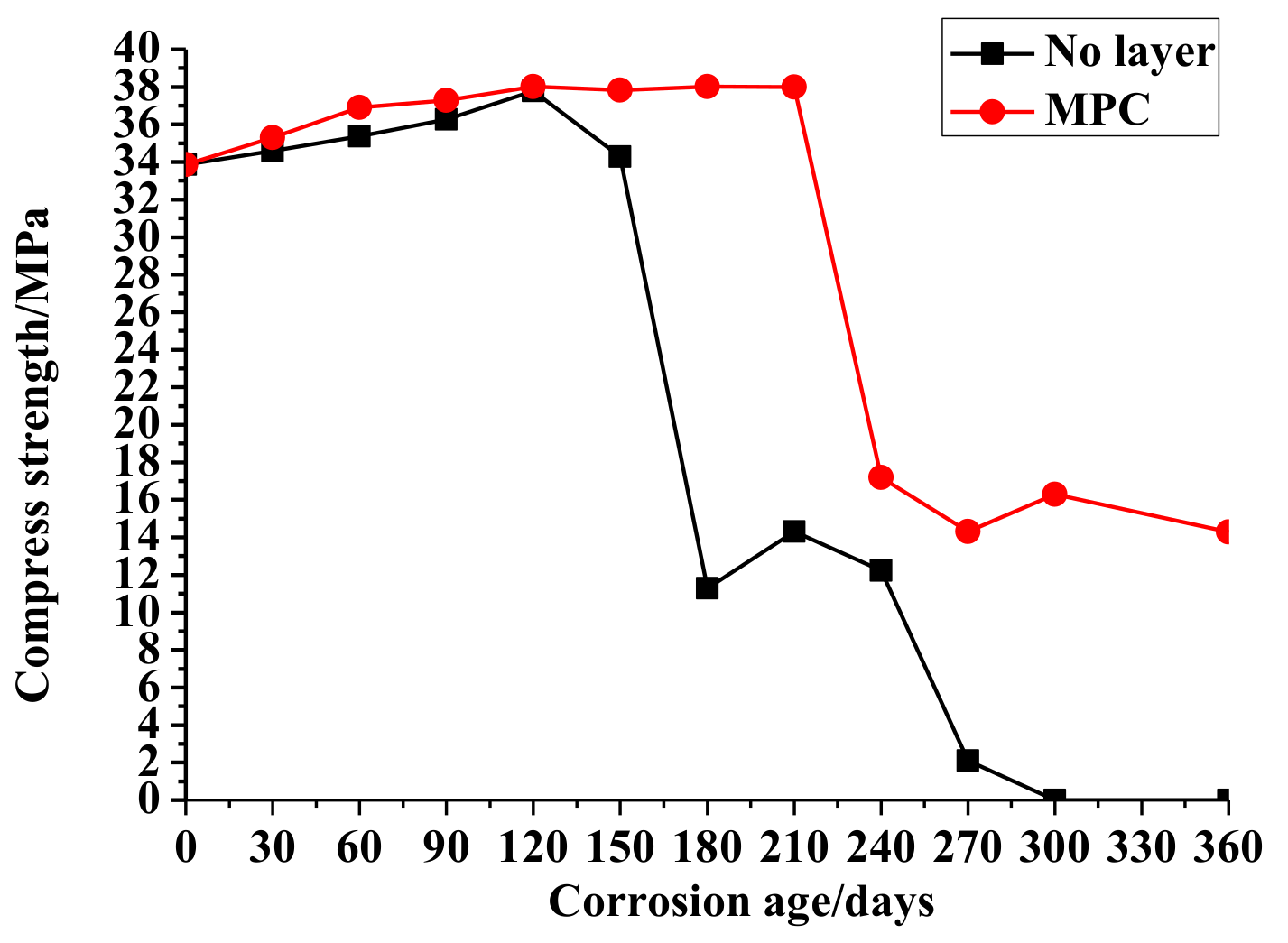
The change of the compressive strengths of the no-layer and MPC-layer concrete cubes by age are shown in Figure 1. The average compressive strength of the no-layer concrete cubes was 20.18 Mpa, and the deviation of compressive strength was 15.44 Mpa. Therefore, the coefficient of variation was 76%. When the corrosion time increased from 0 to 150 days, there was a steady increase of the compressive strength of the no-layer concentrate accordingly. At 180 days, sulfate corrosion damaged the concrete structure surface, leading to the sharp decrease of the compressive strength. In addition, the compressive strength fluctuated from 10 to 15 MPa in the interval from 180 to 240 days. When corrosion continued for 270 days, the damage caused by sulfate erosion eventually caused the collapse of the concrete structures and the sudden decrease of strength until zero.
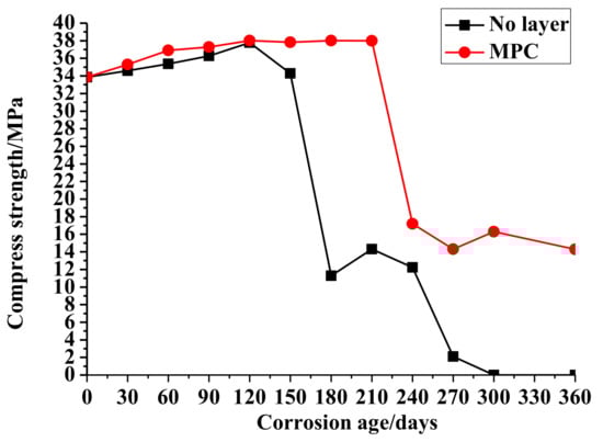
Figure 1.
Compressive strength of concrete in Na2SO4.
3.1.2. MPC Layer Concrete
Figure 1 shows changes in the compressive strength of the MPC layer concrete. The comprehensive strength of the MPC layer concrete had a steady increase from 0 to 210 days. The average compressive strength of MPC layer concrete cubes was 28.77 Mpa while the deviation of compressive strengths was 10.62 Mpa. Thus, the coefficient of variation was 37%. The time for the increase of strength was longer than that of the no-layer concrete due to the protection of the MPC layer. When corrosion occurred for 240 days, the strength mutated reduced by half. From 210 to 360 days, the compressive strength fluctuated from 12 to 18 MPa until the end of the test, as the erosion destroyed only the surface of the concrete structure due to the MPC layer protection. The changes of the concrete strength indicate that an MPC layer can improve the resistance of concrete structures to sulfate attacks.
3.2. Appearances and Morphologies of Coated Concretes
3.2.1. 90 Days
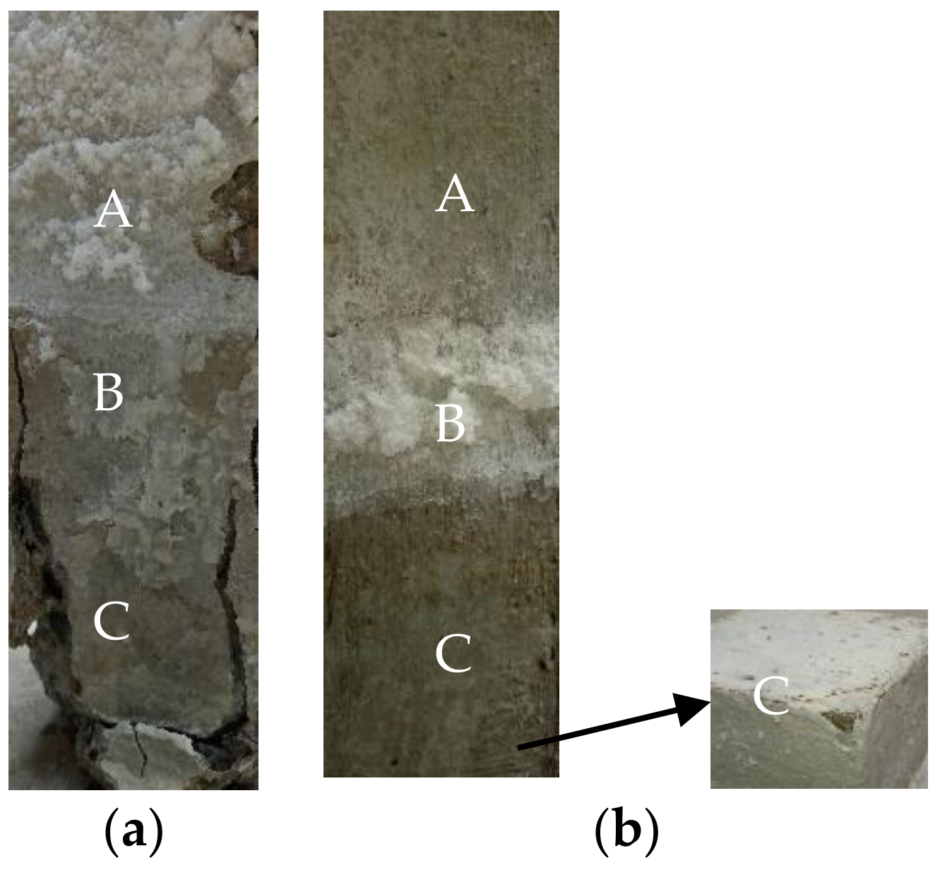
The appearances of the no-layer and MPC layer concretes that were semi-soaked for 90 days in the sulfate solution can be found in Figure 2, showing that they share similar appearances and morphologies after being semi-soaked for 90 days. Moreover, the white crystals (Na2SO4) gradually increased in number and the specimen surface was well preserved with the increase of semi-soaking time. This division explains the crystallization phenomenon, in which salt precipitated as the sulfate solution drastically increased the concentration of salt due to the water evaporation in the adsorption region of the concrete. The adsorption region of the uncoated concrete had the largest number of precipitated white crystals, whereas the adsorption region of the MPC layer concrete had the least. The above findings prove that the layer played a certain role in protecting concrete from sulfate erosion.
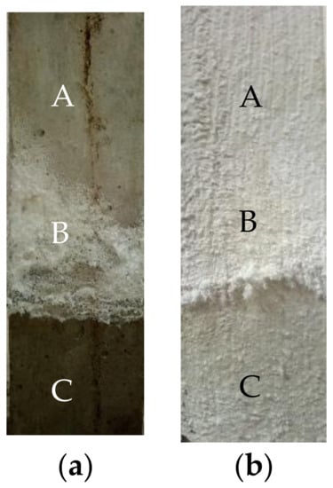
Figure 2.
Morphology of concrete specimens immersed for 90 days: (a) No layer; (b) MPC. (A: Atmospheric region zone; B: Crystal precipitation zone; C: Immersion zone).
3.2.2. 210 Days
The appearances of the no-layer and MPC layer concretes, after being semi-soaked in the sulfate solution for 210 days, are shown in Figure 3. According to Figure 3a, there were dramatic changes over the appearances of these concretes after 210 days of semi-soaking. White flocculent crystals gradually precipitated in the adsorption area of the no-layer concrete during the semi-soaking time. The amount of precipitate continued to increase, and they propagated toward the atmosphere region. The surface near the edge of the specimen soaking region was considerably pitted, whereas the central part was barely pitted. The concrete surface in the corner angles had different levels of peeling. Falling soaking region corners, falling-off cement slurry, and an exposed coarse aggregate were observed.
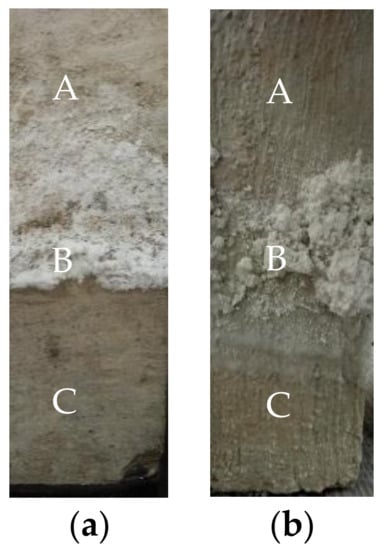
Figure 3.
Morphology of concrete specimens immersed for 210 days: (a) No layer; (b) MPC. (A: Atmospheric region zone; B: Crystal precipitation zone; C: Immersion zone).
Figure 3b shows that the concrete adsorption region of the MPC layer was covered with white flocculent crystals (Na2SO4). After the removal of these crystals, no pits were found on the specimen surface, indicating that the concrete surface remained intact. In addition, the soaking region of the specimen was also intact, and did not exhibit a pitted surface and falling corners.
3.2.3. 360 Days
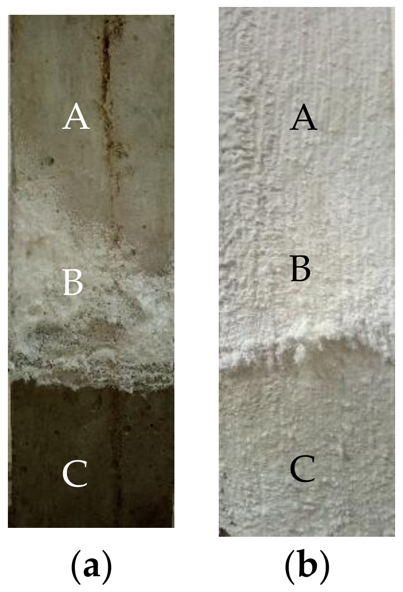
The appearances of the no-layer and MPC concretes that were semi-soaked for 360 days in the sulfate solution are presented in Figure 4, and became considerably different from how they appeared before the soaking. The surface of the no-layer specimen was featured by extensive coverage of white crystals and a seriously stripped adsorption area in Figure 4a. There were leakage and longitudinal cracks developed in the soaking region of the coarse aggregate, and the surface mortar fell off with aggravated or even crisp and loose corrosion. No erosion was observed in the atmosphere.
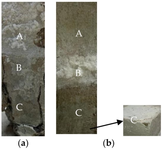
Figure 4.
Morphology of concrete specimens immersed for 360 days: (a) No layer; (b) MPC. (A: Atmospheric region zone; B: Crystal precipitation zone; C: Immersion zone).
Figure 4b shows that the adsorption region of the MPC layer concrete gathered whiter flocculent materials as the coverage continued to expand. Although corners of the cement soaking region were observed to fall, the coarse aggregate was not exposed.
In summary, the after-corrosion concretes can be classified into the following three parts: soaking, adsorption, and atmosphere regions. In the semi-soaked state, the corrosion process of the concrete specimen in the sulfate solution began with the precipitation of white flocculent sulfate crystals, associated with the increases in internal crystallization and chemical corrosion products in the adsorption region. Moreover, cracks that initially appeared at the corner of the soaking region were observed on the immersed area of the concrete surface. The greater concentration of sulfate in the sulfate solution usually leads to more serious corrosion phenomena. In addition, the MPC layer demonstrated better protective effects by greatly protecting the integrity of the concrete specimen.
3.3. Evolution of Microstructure of MPC Protective Layer
3.3.1. Changes in MPC Protective Layer
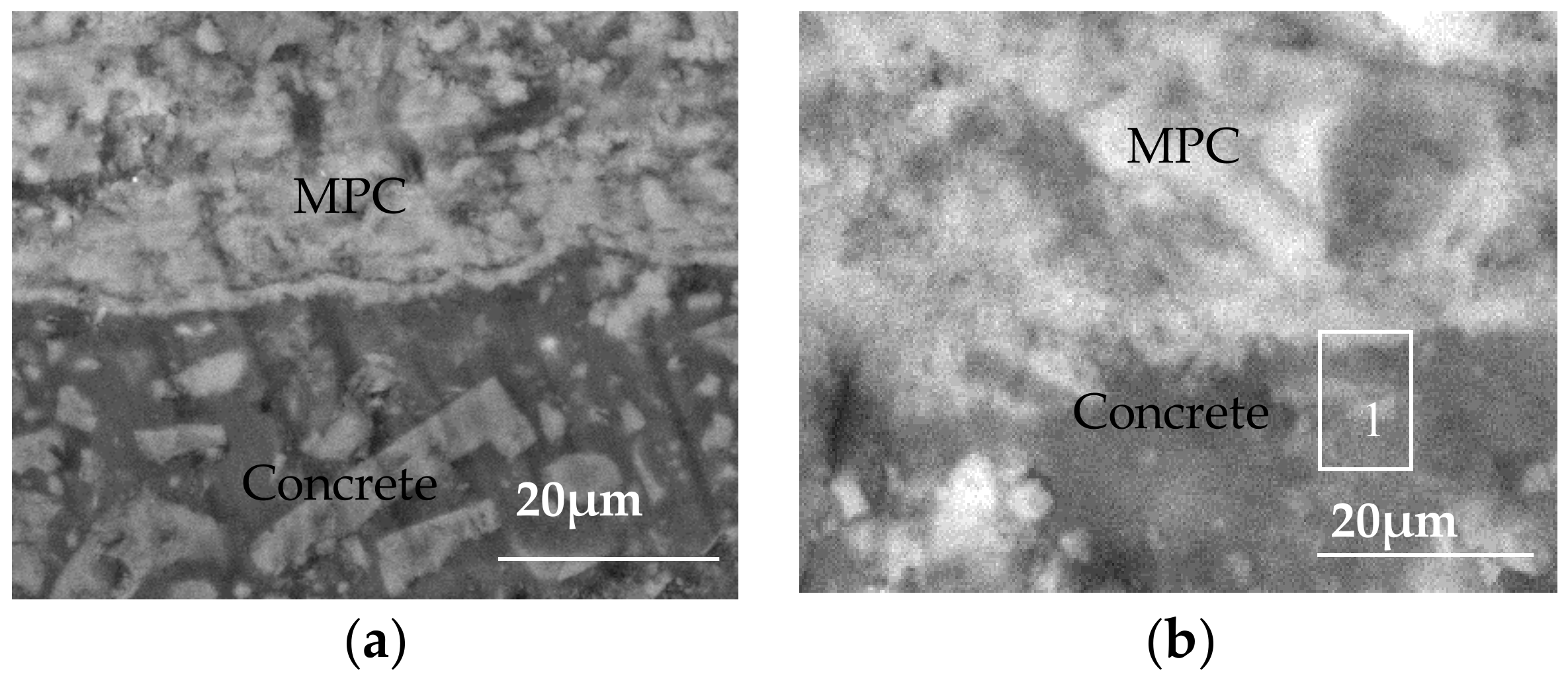
The morphology, observed via SEM, of the interface between the MPC layer and the concrete substrate is shown in Figure 5. During the initial contact between the concrete specimens and the sulfate solution, corrosive ions entered the internal concrete structures under the synergistic effect of capillary adsorption and water evaporation. Figure 5a shows that the MPC layer was tightly associated with the concrete substrate in the early corrosion period, thus forming a dense and uniform protective layer that separated the concrete structure from the external environment, and the filling up of pores in the concrete structure. This protective layer relieved the wicking effect and prevented the formation of high-concentration pore solution areas in the concrete structure, and consequently significantly kept sulfate ions out of the concrete structures. This layer can protect concrete structures from sulfate corrosion when it is integrated.

Figure 5.
SEM of MPC protection layer and concrete matrix: (a) 90 days; (b) 360 days.
Figure 5b shows that the MPC layer remained intact from the concrete interface though the corrosion continued. In the late corrosion period, the MPC and the concrete substrate had an ambiguous interface. Hydration products of the two cement materials interweaved and penetrated mutually. Specifically, hydration products of the MPC layer were embedded into the uneven surfaces of the concrete structures, like needles, after being solidified. The products, thereby, were bounded tightly through mechanical interlocking. The gaps were blocked by the products while a protective layer was formed to enhance the sulfate corrosion resistance of the concrete structure. Meanwhile, the internal concrete structures were formed. The density, therefore, was lowered. A dense and hard surface was formed on the concrete surface. Surface crystallization was significantly relieved in the exposed region of the MPC layer, which contributed to the significantly reduced sulfate radicals concentrating in the immersed region, and thus improved the sulfate corrosion resistance of the concrete structure.
To analyze the products and structures in the interface micro region between the MPC layer and the concrete, EDS analysis was conducted in Position 1, as shown in Figure 5b. The areas close to each side of the bonding interface were selected as the samples in the test. Table 6 presents the EDS analysis. Microstructure and element composition and component analysis showed that the major hydration products of Portland cement were the needle-like clear crystals in the figure, namely, the hydrated calcium silicate gel (C–S–H). In addition, the EDS analysis suggested that the major elements were calcium (Ca), magnesium (Mg), nitrogen (N), phosphorus (P), sodium (Na), silicon (Si) and oxygen (O). According to molecular weight calculations, its ratio conformed to the major hydration products of magnesium phosphate cement-based materials referred to as struvite (MgNH4PO4·6H2O). Different hydration products were mixed, overlapped, and tightly interweaved with each other at the interface to form a sheet or block of the gel hydration products so as to enhance the bond strength.
Table 6.
EDS of interface in Na2SO4 t/(wt %).
3.3.2. Structure of MPC Protective Layer
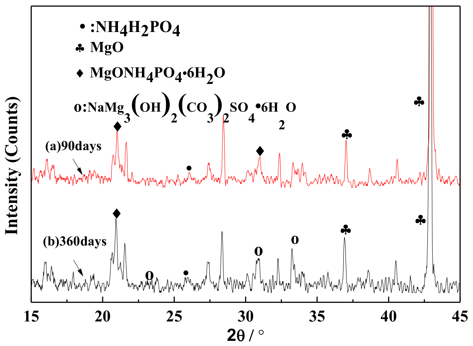
XRD curves of the MPC layer in the early and late corrosion periods are shown in Figure 6. The two curves represent the XRD curves of the MPC coating at 90 and 360 days corrosion. The MgO diffraction peak in the XRD curve of the MPC coating is strong, thus indicating the existence of an unhydrated MgO. In the early corrosion period, curve (a) is dominated by the diffraction peaks of MgO and MgNH4PO4·6H2O, indicating that the MPC coating is composed of MgNH4PO4·6H2O (struvite), which is an important gel in coating adhesives. In the late corrosion period, curve (b) reflects the diffraction of the new product of NaMg3(OH)2(CO3)2SO4·6H2O apart from the diffraction peaks of MgO and NH4H2PO4, indicating the reaction of MPC coating with SO42− in the sulfate solution that produces the new stable complex, namely NaMg3(OH)2(CO3)2SO4·6H2O. Complex solutions are even proven to be stable in the sulfate environment and play a major role in coating performance.
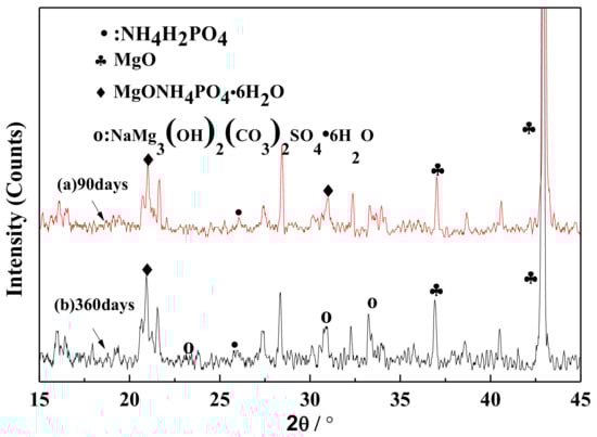
Figure 6.
XRD of the MPC protection layer in the early and late corrosion stages: (a) 90 days; (b) 360 days.
The SEM results of the MPC layer in the early and late corrosion periods can be found in Figure 7. A large amount of MgNH4PO4·6H2O and a smaller amount of unreacted MgO were observed in the MPC layer at 90 days corrosion. Hydration products mainly come in a worm-like and interwoven order. The network structure, therefore, was formed on the concrete substrate. In Figure 7b, the MPC layer in the sulfate solution and the needle-like hydration product NaMg3(OH)2(CO3)2SO4·6H2O were scattered in the network structure at 360 days corrosion. These solutions interact mutually and effectively to fill the gaps among the MPC particles, thus possibly improving the protective effect and structural density, while at the same time reducing structural porosity. Consequently, grains of NaMg3(OH)2(CO3)2SO4·6H2O were expanded while the structural density was increased correspondingly. Therefore, an MPC layer with a dense structure can be applied to protect the concrete surface through forming an isolating layer. Such an isolating layer can hinder not only the reaction between the concrete and the sulfate ions but also the connection between the internal and external environments of the concrete structures. The capillary effect of the porous concrete structure was weakened significantly, which greatly improved the resistance of the concrete structure to sulfate corrosion [28].
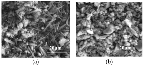
Figure 7.
SEM of the MPC protection layer in the early and late corrosion stages: (a) 90 days; (b) 360 days.
4. Conclusions
- (1)
- The surface of the concrete structure was divided into three parts after being exposed to the sulfate erosion environment, namely the atmosphere, adsorption, and soaking regions. Corrosion was mainly concentrated in the adsorption and soaking regions, but the corrosion features in them were quite different. That is, the damage caused by sulfate to the concrete in the soaking region was more intense than that in the adsorption region.
- (2)
- The comparison of concrete compressive strength changes demonstrates the ability of the MPC layer to improve the compressive strength and external appearance of the specimens in the sulfate environment.
- (3)
- An MPC layer can greatly enhance the resistance of concrete to sulfate attacks in sulfate environments, and is achieved by forming new complexes through reaction with sulfate ions. In this context, the layer structure is more compact than before while the bond strength between the layer and the concrete is strengthened accordingly. The resistance of the MPC layer concrete to sulfate attacks is thus enhanced significantly.
Acknowledgments
The authors are grateful for the financial support from the Fundamental Research Funds for the Central Universities (2017XKQY014).
Author Contributions
Jun Li and Yongsheng Ji conceived and designed the experiments; Guodong Huang performed the experiments; Linglei Zhang analyzed the data; Jun Li wrote the paper.
Conflicts of Interest
The authors declare no conflict of interest.
References
- Wu, C.; Chen, W.; Zhang, H.; Yu, H.; Zhang, W.; Jiang, N.; Liu, L. The hydration mechanism and performance of Modified magnesium oxy sulfate cement by tartaric acid. Constr. Build. Mater. 2017, 144, 516–524. [Google Scholar] [CrossRef]
- Li, Y.; Bai, W.; Shi, T. A study of the bonding performance of magnesium phosphate cement on mortar and concrete. Constr. Build. Mater. 2017, 142, 459–468. [Google Scholar] [CrossRef]
- Ramey, G.E.; Moore, R.K.; Parker, F., Jr.; Strickland, A.M. Laboratory evaluation of four rapid-setting concrete patching materials. Transp. Res. Rec. 1985, 1041, 47–52. [Google Scholar]
- Michałowski, T.; Pietrzyk, A. A thermodynamic study of struvite + water system. Talanta 2006, 68, 594–601. [Google Scholar] [CrossRef] [PubMed]
- Jiang, H.Y.; Chen, C.M. Influence of admixtures on the dissolution rate of chloride ion in magnesia cement. J. Wuhan Univ. Technol. 2010, 32, 37–40. [Google Scholar]
- Li, Y.; Li, Y.; Shi, T.; Li, J. Experimental study on mechanical properties and fracture toughness of magnesium phosphatecement. Constr. Build. Mater. 2015, 96, 345–352. [Google Scholar] [CrossRef]
- Li, Y.; Chen, B. Factors that affect the properties of magnesium phosphate cement. Constr. Build. Mater. 2013, 47, 977–983. [Google Scholar] [CrossRef]
- Soudee, E.; Pera, J. Influence of magnesia surface on the setting time of magnesia-phosphate cement. Cem. Concr. Res. 2002, 32, 153–157. [Google Scholar] [CrossRef]
- Tan, Y.; Yu, H.; Li, Y.; Bi, W.; Yao, X. The effect of slag on the properties of magnesium potassium phosphate cement. Constr. Build. Mater. 2016, 126, 313–320. [Google Scholar] [CrossRef]
- Ding, Z. Research of Magnesium Phosphosilicate Cement. Ph.D. Thesis, Hong Kong University of Science and Technology, Hong Kong, China, January 2005; pp. 253–286. [Google Scholar]
- Yang, Q.; Zhu, B.; Wu, X. Characteristics and durability test of magnesium phosphate cement-based material for rapid of concrete. Mater. Struct. 2000, 33, 229–234. [Google Scholar] [CrossRef]
- Abutaha, F.; Abdul Razak, H.; Ibrahim, H.A. Effect of coating palm oil clinker aggregate on the engineering properties of normal grade concrete. Coatings 2017, 7, 175. [Google Scholar] [CrossRef]
- Carmona-Quiroga, P.M.; Jacobs, R.M.; Viles, H.A. Weathering of two anti-graffiti protective coatings on concrete paving slabs. Coatings 2017, 7, 1. [Google Scholar] [CrossRef]
- Climent, M.Á.; Carmona, J.; Garcés, P. Graphite-cement paste: A new coating of reinforced concrete structural elements for the application of electrochemical anti-corrosion treatments. Coatings 2016, 6, 32. [Google Scholar] [CrossRef]
- Mors, R.; Jonkers, H. Effect on concrete surface water absorption upon addition of lactate derived agent. Coatings 2016, 7, 51. [Google Scholar] [CrossRef]
- Safiuddin, M. Concrete damage in field conditions and protective sealer and coating systems. Coatings 2016, 7, 99. [Google Scholar] [CrossRef]
- Nikoo, M.; Sadowski, Ł.; Nikoo, M. Prediction of the corrosion current density in reinforced concrete using a self-organizing feature map. Coatings 2017, 7, 160. [Google Scholar] [CrossRef]
- Yang, Q.; Zhang, S.; Wu, X. Deicer-scaling resistance of phosphate cement-based binder for rapid of concrete. Cem. Concr. Res. 2002, 32, 165–168. [Google Scholar] [CrossRef]
- Yang, Q.; Zhu, B.; Zhang, S.; Wu, X. Properties and applications of magnesia-phosphate cement mortar for rapid of concrete. Cem. Concr. Res. 2000, 30, 1807–1813. [Google Scholar] [CrossRef]
- Zhu, D.; Zongjin, L. High early strength magnesium phosphosilicate cement. Chin. J. Mater. Res. 2006, 20, 141–147. (In Chinese) [Google Scholar]
- Yu, B.; Chen, Z.; Yu, L. Water-resisting ability of cemented broken rocks. Int. J. Min. Sci. Technol. 2016, 26, 449–454. [Google Scholar] [CrossRef]
- Yang, J. Construction Method of Repairing Protective Layer of Reinforced Concrete Structure. China Invention Patent ZL 2015104528590, 11 November 2015. [Google Scholar]
- Yang, J. Preparation and Method of Magnesium Potassium Phosphate Cement Fireproof Protection Layer for Steel Structure. China Invention Patent ZL 2016109076541, 15 March 2017. [Google Scholar]
- Zhu, C.; Chang, X.; Men, Y.; Luo, X. Modeling of grout crack of rockbolt grouted system. Int. J. Min. Sci. Technol. 2015, 25, 73–77. [Google Scholar]
- Jun, L.; Yong-sheng, J.; Guodong, H.; Cheng, J. Retardation and reaction mechanisms of magnesium phosphate cement mixed with glacial acetic acid. RSC Adv. 2017, 7, 46852–46857. [Google Scholar] [CrossRef]
- JGJ55-2011 Specification for Mix Proportion Design of Ordinary Concrete; Ministry of Housing and Urban-Rural Construction of the People’s Republic of China: Beijing, China, 2011. (In Chinese)
- GB 50107-2010 Standard for Test and Evaluation of Concrete Compression Strength; Ministry of Housing and Urban-Rural Construction of the People’s Republic of China: Beijing, China, 2010. (In Chinese)
- Liu, Z.; Xiao, J.; Huang, H.; Yuan, Q.; Deng, D. Physicochemical study on the interface zone of concrete exposed to different slfate attack. J. Wuhan Univ. Technol. Mater. Sci. 2006, 1, 167–174. [Google Scholar]


© 2018 by the authors. Licensee MDPI, Basel, Switzerland. This article is an open access article distributed under the terms and conditions of the Creative Commons Attribution (CC BY) license (http://creativecommons.org/licenses/by/4.0/).