1. Introduction
Modern industry is heading to the “factory in the machine” concept, where hybrid machines that combine additive and machining operations are gaining relevance thanks to the fact that they enable to build ready to use products in a single machine [
1,
2]. The integration of laser-based additive and machining processes results in a combined process that strengthens both processes advantages [
3] and process time reduction [
4]. Evidence of this are the hybrid machine solutions developed by the most advanced machine tool companies, such as DMG Mori, Mazak, Okuma and many other smaller but leading companies such as Ibarmia. All of them use the Laser Metal Deposition (LMD) or Direct Metal Deposition (DMD) as an additive process, where powder shaped filler material is added.
Laser Metal Deposition enables to build free-form parts with almost no geometrical restriction and high quality metallurgy. The process is based on the generation of a melt pool on the surface of the substrate, whereas filler material is simultaneously added in the form of powder or wire [
5]. Line by line, coating layers are generated and, by means of overlapping the subsequent layers, the desired final geometry is obtained.
One of the main applications of LMD is the generation and repair of high added value parts, with the aeronautical sector already starting to introduce this process in the MROs (Maintenance, Repair and Operations) at different airports. For turbine blade and jet engines repair, Inconel 718 is widely used and therefore many authors have focused their work on optimizing the process parameters. For instance, Kumar and Nair studied the Inconel 718 process parameters optimization for obtaining a fine structure, maximize the hardness and reduce porosity [
6]. For this purpose, authors used the Taguchi L9 orthogonal array method. Other researchers have worked on the development of a high-speed imaging-based method for optimizing laser-welding parameters [
7]. Process control algorithm acts on the laser power and pulse duration and enables to obtain pore free welds.
One of the weakest points of the LMD manufactured parts is the existence of pores and many scientific works have been published aiming to reduce their apparition. Authors such as Zeng et al. studied the porosity formation in the LMD process for Ni-based coatings using an image analyze method [
8], but most of the published works focus on analyzing the relation between the process parameters and the resulting porosity.
Ng et al. studied the influence that various process parameters such as laser power, scanning speed, powder mass flow and shielding gas flow rate have in the resultant Inconel 718 clad [
9]. They concluded that porosity is mainly generated due to the gas bubbles dragged into the melt pool by the powder particles.
Following a similar procedure, Zhong et al. analyzed the porosity generation in high-deposition conditions for Inconel 718 [
10]. They concluded that the powder drying treatment considerably reduces the resultant porosity. Moreover, the reduction of the particle size also results in a porosity decrease. In addition, the influence of the shielding gas flow rate and the laser power were also evaluated. In the same direction, Zhou et al. studied the pores generation mechanism: they evaluated the influence of the powder properties, the thermal conductivity of the substrate and the laser power density in the resulting porosity [
11]. However, none of the previously mentioned authors has analyzed the influence of the existence of oil or cutting fluid on the surface in the metallurgical quality of the resulting part.
The preparation of the substrate prior to the material deposition process is very relevant to avoid internal defects such as pores, the entrapment of impurities and ensure the proper bounding between the filler and base materials [
12]. Nevertheless, in hybrid machines where both machining and LMD operations are carried out without loosening the part, the elimination of the intermediate cleaning stage reduces the total manufacturing time and subsequent production costs.
Authors like Barckhoff suggest that before the laser welding operation, any lubricant on the surface must be removed in order to avoid the introduction of gas bubbles and generation of pores [
13]. Moreover, the presence of lubricants on the surface leads to strong fluctuations of the plasma spectra [
14]. The very same conclusion was reached by Alsher et al. in their research work, who proposed a preceding cleaning process to laser welding [
15]. For this purpose, they suggested to use a nanosecond pulsed fiber laser to remove a 20 microns thickness layer of the substrate surface before welding, comparing the obtained results to those without any cleaning. They concluded that the cleaning stage significantly reduces the resulting porosity. Nevertheless, no alternative cleaning methods that do not imply the elimination of material were evaluated.
Hence, it is concluded that there is no research work that quantifies this influence or ensures the quality of the deposited material in the presence of lubricants or cutting fluids. In order to solve this issue, the present research work aims to evaluate the influence of the use of cutting fluids in the LMD process from the point of view of pore generation. To that end, experimental tests of laser metal deposition of Inconel 718 on cutting fluid impregnated specimens have been performed. Images of the cross sections have been analyzed and the porosity and pores size have been estimated. Then, the influence of the different oil concentrations and cleaning methods in the porosity of the clads is discussed. It is concluded that the lower the concentration of oil, less pores are generated. In addition, cleaning stages prove to decrease both the porosity and the pores size present in the clads, attaining levels of porosity comparable to LMD without any coolant.
2. Materials and Methods
The experimental tests described in this study are realized on a Kondia Aktinos 500 (Kondia, Elgoibar, Spain) of 700 × 360 × 380 mm
3 work volume, which is a 5-axis (three linear plus two rotatory axes) conventional milling center rebuilt as a laser processing cell. Besides, a high power Yb:YAG fiber laser, Rofin FL010 (ROFIN-SINAR, Bergkirchen, Germany), with a maximum power output of 1 kW and 1070 nm emitting wavelength is used. The laser beam is guided through an optical multi-mode fiber from the laser source to the processing cell, generating a circular laser spot of approximately 2 mm through a lens of 200 mm focal distance. The powder is fed by means of a Sulzer Metco Twin 10-C powder feeder (Oerlikon Metco, Pfäffikon, Switzerland) and an in-house designed coaxial nozzle, EHU/Coax 2015 (UPV/EHU, Bilbao, Spain) [
16], while argon is used as both carrier and shielding gas.
Inconel 718 and MetcoClad 718 metal powder are used as substrate and filler material, respectively. On the one hand, Inconel 718 is an age-hardenable nickel-chromium alloy that combines corrosion resistance with high strength and good creep rupture strength at high temperatures. Its application fields range from aeronautics and spacecraft to nuclear reactors and gas turbine engines. On the other hand, MetcoClad 718 by Oerlikon Metco is a gas-atomized, nickel-base superalloy powder, with a particle size distribution between 44 and 90 µm and similar in composition to Inconel 718. It has a good corrosion resistance and it also resists creep and stress rupture at elevated temperatures. Its use is indicated for the repair or buildup of nickel-base superalloys or steel parts. The chemical composition of both materials is shown in
Table 1 below.
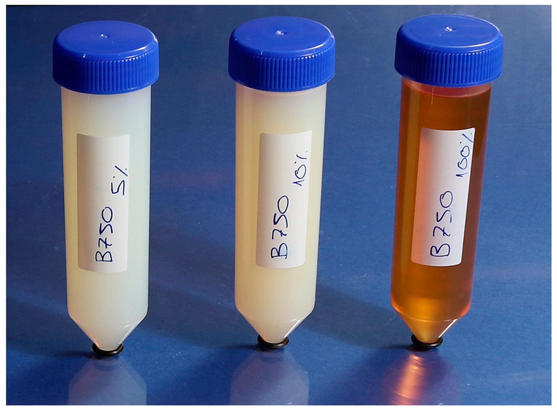
Age-hardened Inconel 718 slabs, with a 42 HRC hardness, are prepared and impregnated with the help of a dropper with an oil-water emulsion containing Houghton HOCUT B-750 cutting fluid (Houghton International Inc., Valley Forge, PA, USA), so that the surface of the part was completely covered. HOCUT B-750 is a water-soluble fluid, composed of mineral oil and special emulsifiers with anti-corrosive additives. It is widely used as a coolant and lubricant in machining operations. According to the manufacturer, oil concentrations between 5% and 10% are recommended for machining [
19]. Therefore, concentrations of 5%, 10% and 100% are selected for the realization of this study, simulating the last one a situation where the water is evaporated and only pure oil remains. Test tubes containing the three different oil emulsions are shown in
Figure 1.
For each concentration and after impregnating the part with the corresponding cutting fluid, the same LMD tests have been carried out, using the same process parameters. However, three different cleaning methods are performed for each case, giving rise to the list of experiments shown in
Table 2. In addition, process parameters employed for all the tests are also detailed.
A first reference layer is deposited with no cutting fluid in order to determine clean results and establish a reference. Then, direct deposition (with no cleaning), deposition after cleaning with compressed air (air blasted) and after laser cleaning are realized. The air blasting is carried out with 7 bar air pressure, while the laser cleaning is performed at a laser power of 200 W and 100 mm focal distance. All the experiments are performed by depositing a single layer composed of three clads and following a zig-zag strategy. The reason for depositing a single layer is that once the first layer is deposited, it has been experimentally detected that the surface of this new layer is free from cutting fluid remnants.
Once the experimental tests are finished, the samples are cross sectioned and polished until all scratches are removed. Three different cross sections are evaluated for each sample in order to obtain average values. To that end, images of the cross sections are acquired by means of an optical microscope. High-resolution images are obtained, enabling to detect pores of a minimum size of 3.0 μm. This resolution is considered appropriate, as smaller pores have a minimal influence on the mechanical properties of the resulting part.
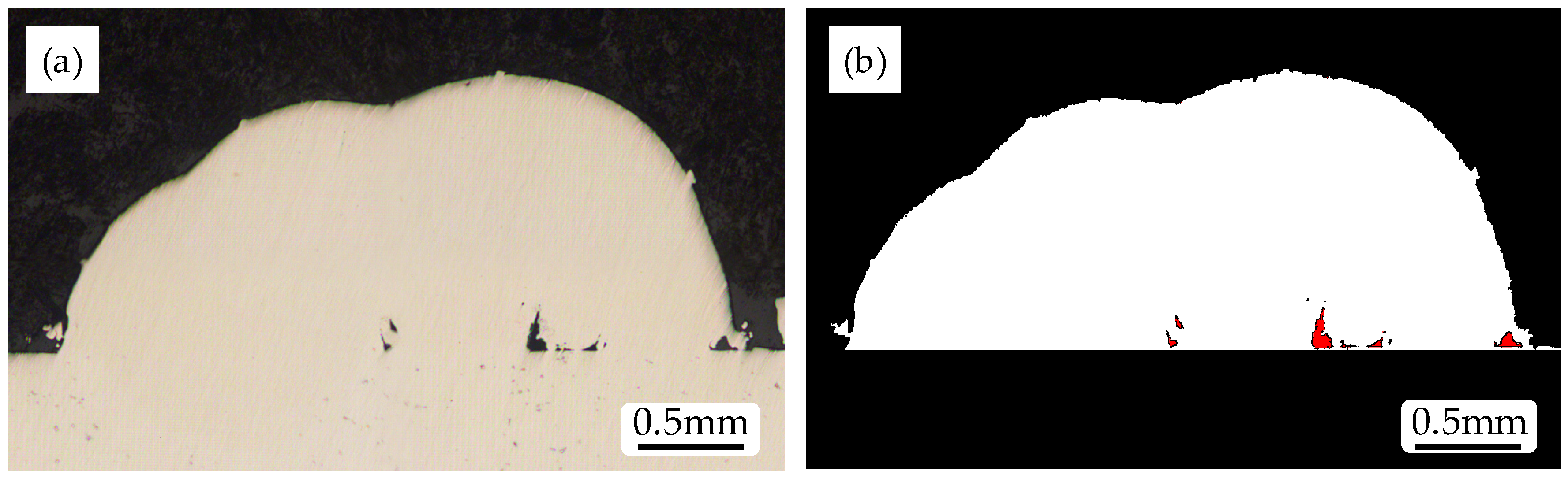
Afterwards, the images are analyzed using Matlab R2017b (MathWorks, Natick, MA, USA), software in which authors have developed a program that enables to detect the percentage and size of pores in the region of the deposited material. For this purpose, in a first step the program detects and eliminates all material belonging to the phenolic resin used for encapsulating the samples. In a second step, the material belonging to the substrate is detected and eliminated. Lastly, porosity is evaluated in the deposited material as the number of void pores.
An example of how the Matlab program developed works is presented in
Figure 2. The original image acquired with the microscope is shown in
Figure 2a, while the resulting post-processed image is displayed in
Figure 2b. On the one hand, the considered deposited material and pores are marked in white and red, respectively. On the other hand, neglected material such as substrate and resin is shown in black.
3. Results and Discussion
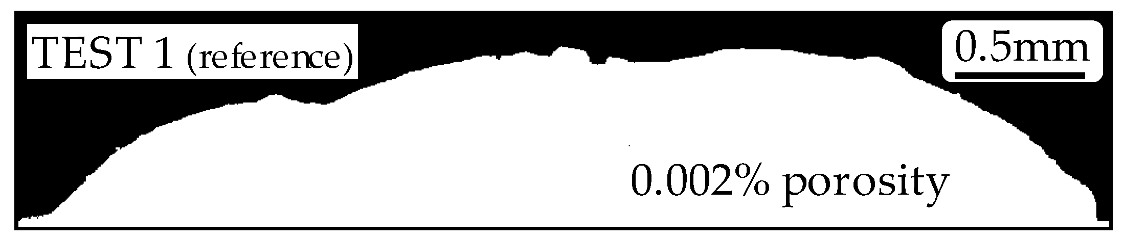
In the present section, results obtained after the evaluation of the cross sections of the different test samples are detailed. The software Matlab R2017b is used for determining both the percentage of porosity of each cross section in terms of surface and size of the pores. The resulting image of the cross section and porosity of the reference test is shown in
Figure 3.
The reference test (test No. 1) is that corresponding to a clean substrate. In this test, an almost zero porosity is achieved (0.002% of the total deposited material) with an average diameter of the pores below 10 μm and therefore, these values are considered as a reference that determines the maximum quality to be achieved with the employed equipment and process parameters.
3.1. 5% Concentration Cutting Fluid
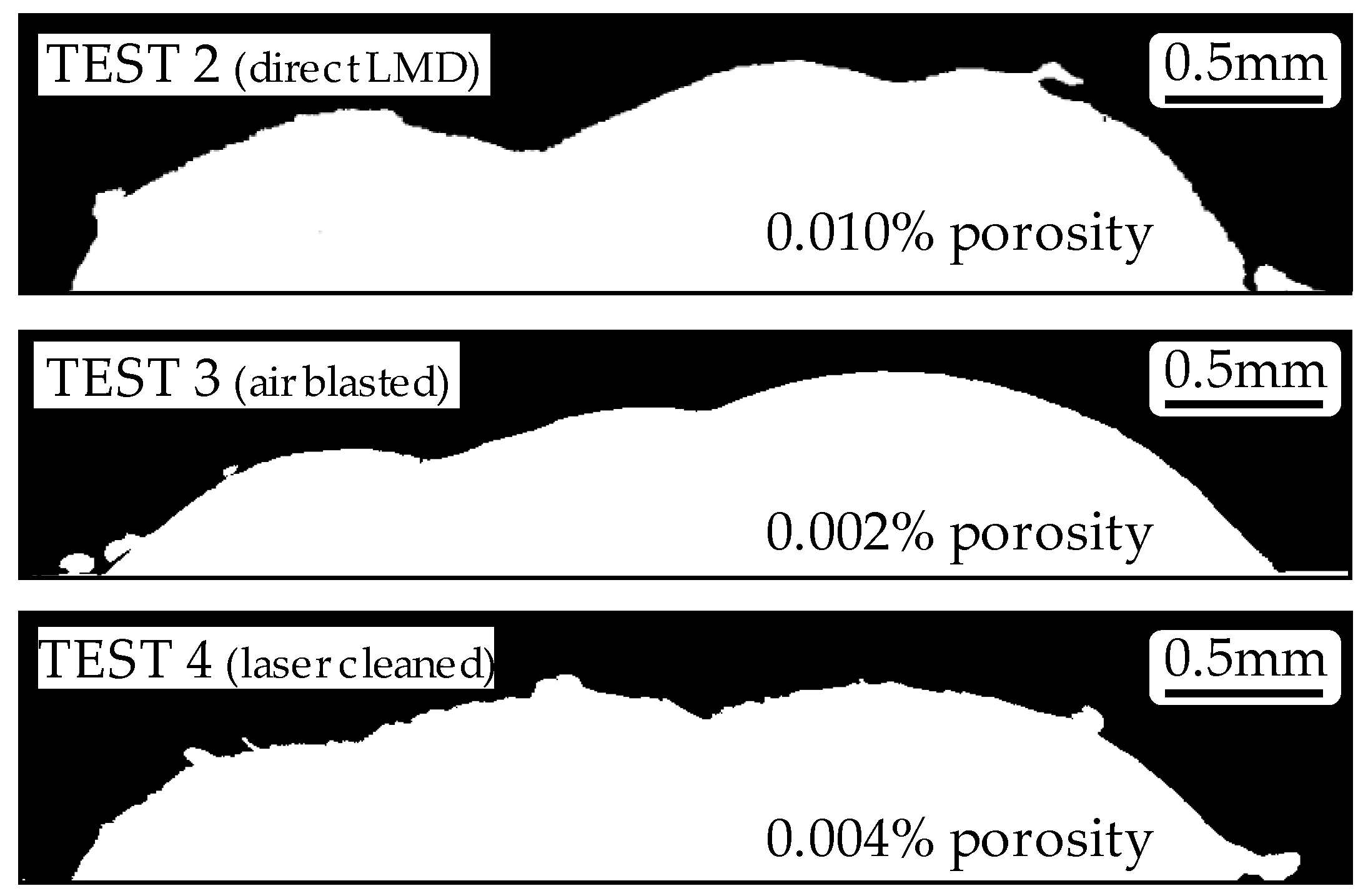
In
Figure 4, cross sections of the deposited material are displayed. In the case of test No. 2, a 0.010% average porosity value is found, whereas in the cases where the surface is cleaned by means of air blasting and the laser itself, tests No. 3 and 4 respectively, porosity values comparable to those encountered in test No. 1 are found. Moreover, all pores have a size below 10 μm in diameter. This is why no porosity distribution graphs are shown regarding these 5% concentration cutting fluid tests.
Nevertheless, it is also noticed that the existence of cutting fluid on the surface of the substrate influences the appearance and shape of the deposited material. Consequently, this fact generates variations on the resulting height of the deposited layer, that may affect the stability of the process when depositing the following layers.
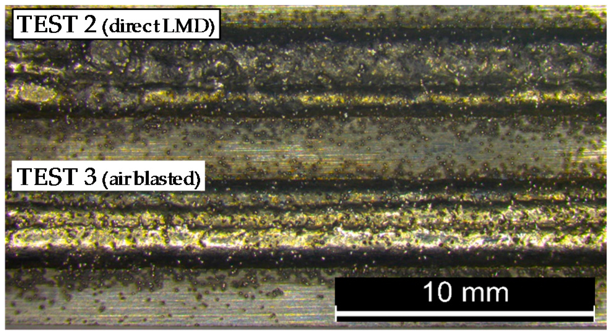
The external appearance of tests No. 2 and 3 is shown in
Figure 5. On the one hand, it is noted that the direct test (test No. 2) looks darker and non-homogeneous because of the slag generated in the LMD process. On the other hand, the air blasted sample (test No. 3) looks brighter and without external anomalies.
3.2. 10% Concentration Cutting Fluid
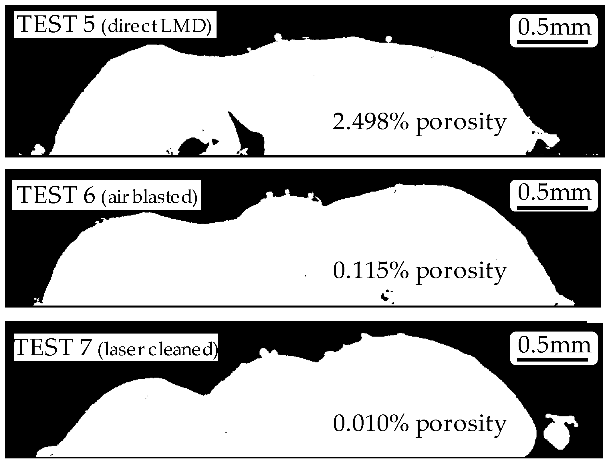
As the content of oil in the cutting fluid is increased, the resulting porosity in the deposited material is also increased. In fact, this increase is caused by the interaction of LMD and the cutting fluid. When the cutting fluid is burnt due to LMD, the vapors generated are trapped inside the molten material because the melt pool solidifies so fast that there is not enough time for the fumes to exit. In the case of direct deposition (test No. 5) a 2.498% of average porosity is measured, where pores up to 300 μm diameter are detected. Thanks to the intermediate cleaning stages, porosity values are drastically reduced (see
Figure 6 (tests No. 6 and 7)), being the lowest average value, 0.010%, achieved with laser cleaning.
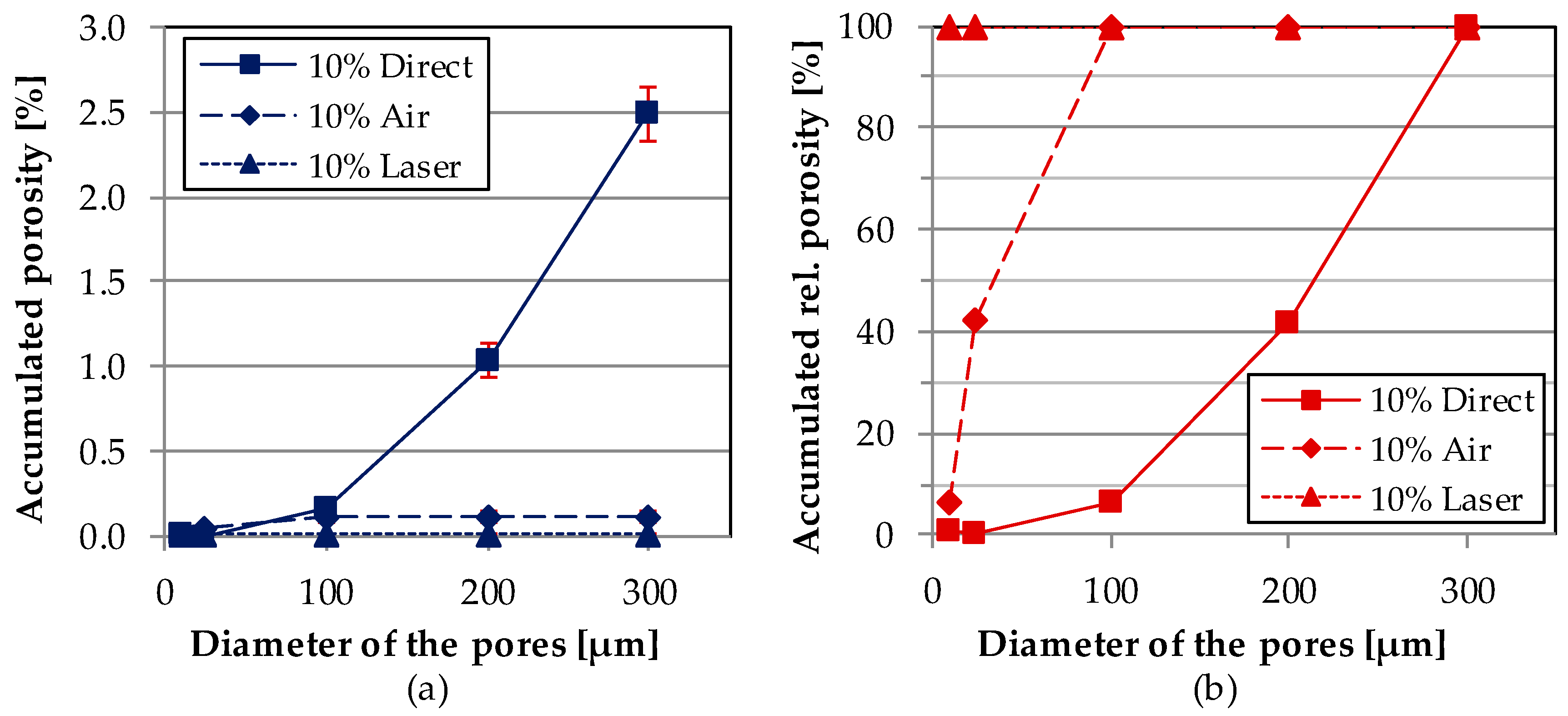
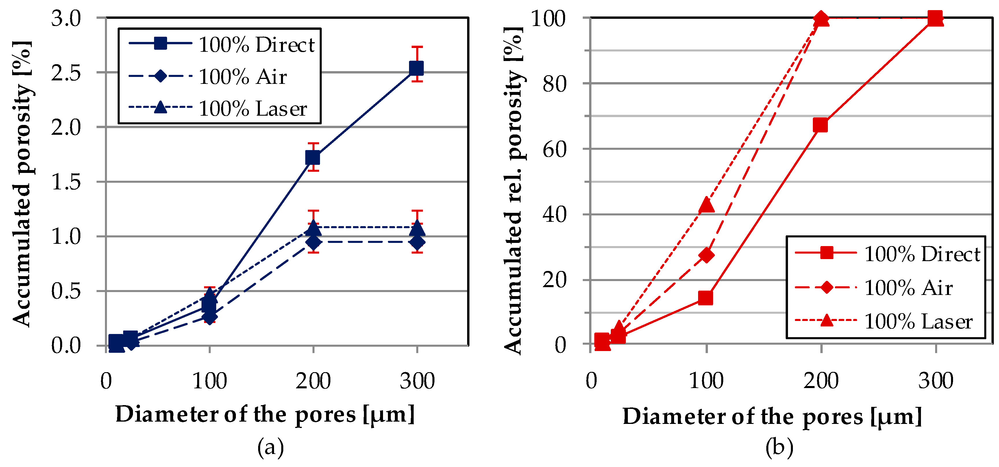
Average porosity results are analyzed by means of graphs representing two kinds of accumulated porosity. Despite single porosity values being measured, they are connected with straight lines in order to make the obtained results more understandable. On the one hand, in
Figure 7a, the accumulated porosity with regard to the total deposited material in function of the diameter of the pores is shown. In all cases, pore size remains below 300 μm diameter.
On the other hand, in
Figure 7b the accumulated relative porosity with regard to the total amount of pores of each test in function of the size of the pores is represented. The improvement introduced by the cleaning stages is noticeable in this figure. While test No. 5 (10% Direct) results show that 60% of the pores have a size of 200–300 μm diameter, tests that include cleaning stages show a lowering of the pores size. For instance, the analysis of test No. 6 (10% Air) determines that all the pores remain below 100 μm diameter and, in the case of test No. 7 (10% Laser), all pores have a size below 10 μm.
When comparing the obtained results, it is concluded that the cleaning process not only reduces the total amount of porosity, but also the size of the pores. In addition, best results are attained with a laser cleaning stage, achieving porosity results comparable to the reference test.
3.3. 100% Concentration Cutting Fluid
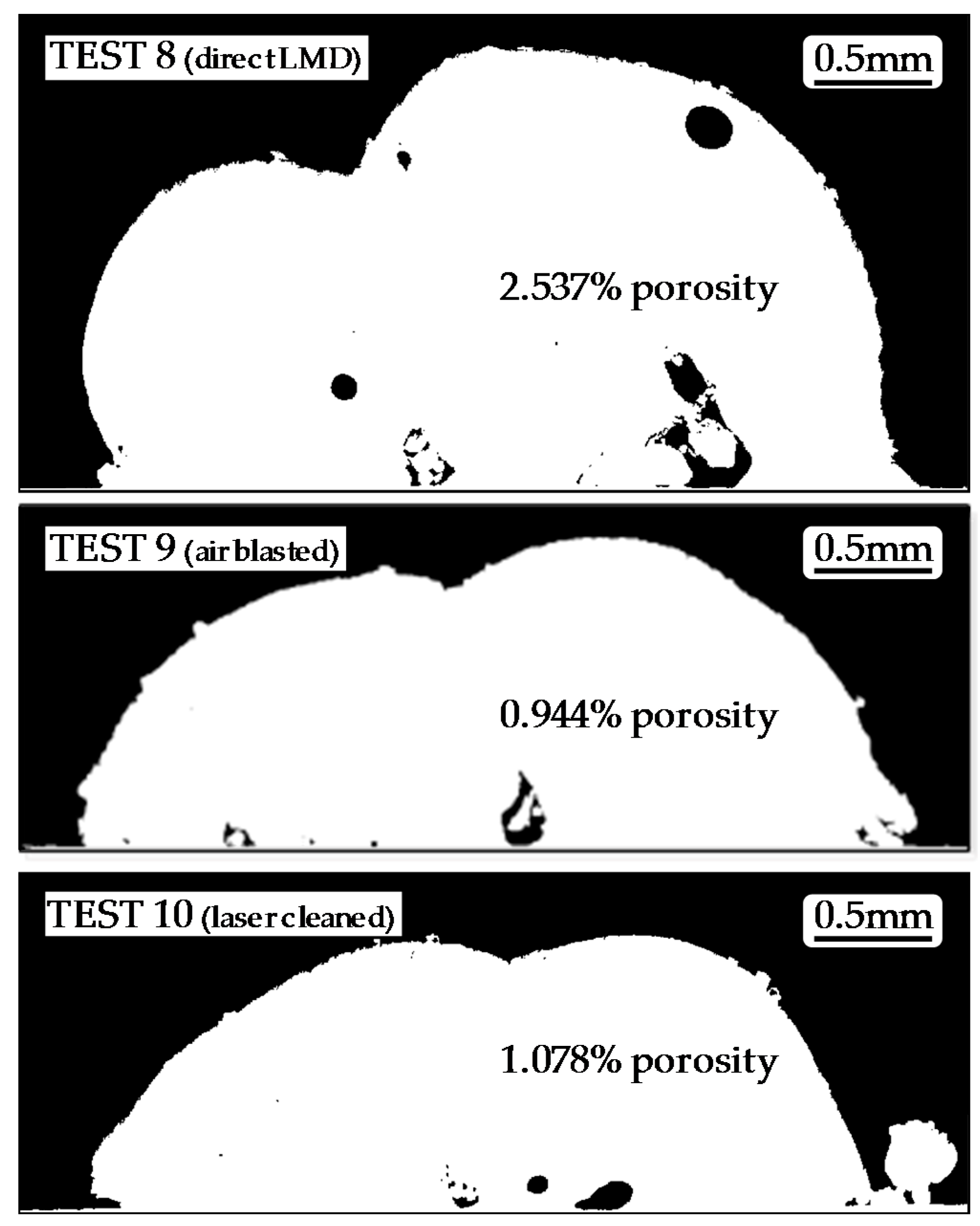
A 100% oil concentration corresponds to the situation in which all of the water of the cutting fluid has evaporated and only oil remains. From
Figure 8, it may be noted that obtained results are nothing like the shape of the deposited material from the previous tests. Much higher layer heights are achieved, but also higher porosity values. The increase in the layer height is induced by the generation of a mixture between the powder particles and pure oil, leading to the accumulation of powder on the surface of the substrate.
As shown in
Figure 9, thanks to the air blasting and laser cleaning processes, porosity values are considerably decreased. Test No. 8 (100% Direct) presents pores below 300 μm diameter, and around 70% of them have a size below 200 μm. Air and laser cleaned tests present improved results with reduced porosity and in all cases with a size below 200 μm diameter.
Thus, the size of the pores is reduced thanks to the cleaning processes, but not sufficiently to be compared to the reference test (in both cases an average porosity around 1% is obtained). Once again, the smallest pore distribution is achieved when the surface of the substrate is cleaned with the defocused laser before the LMD process.
4. Conclusions
In the present work, the influence of the use of cutting fluid in hybrid processes of machining and LMD is investigated. The quality of the clads in terms of porosity is evaluated by means of an own developed Matlab program. According to the attained results, the following conclusions can be drawn:
- (1)
Attending to the oil concentration of the cutting fluid, the lower the concentration, the lower the amount of pores. When low concentrations (e.g., 5% Houghton HOCUT B-750 cutting fluid emulsion) are employed, there is practically no need for an intermediate substrate surface cleaning step between the machining and LMD operations. However, it is highly recommended in order to obtain porosity values comparable to the reference case and hence ensure the stability of the process. On the contrary, substrate cleaning results critical as the percentage of oil of the cutting fluid is increased. For concentration values of 10%, the direct LMD is not acceptable. Nevertheless, with the laser cleaning stage, acceptable results in terms of porosity are achieved. In the case of 100% concentration tests, no results comparable to the reference test are attained. Hence, the water content of the emulsion cannot be evaporated to that point.
- (2)
With regard to the cleaning processes, if the cutting fluid is not properly removed from the surface of the substrate, a mixture between the remaining oil and the powder particles is generated. Consequently, instead of a pure LMD process, a sum of direct and preplaced powder additive process is achieved, which results in an increase of the material deposition rate and higher clad heights. In that condition, the layer-by-layer process may become unstable. In addition, the best results are generally obtained after applying a laser cleaning stage. Nevertheless, the introduction of any cleaning step previous to LMD, especially the laser cleaning, involves lengthening in time the whole manufacturing process.
- (3)
To sum up, the direct LMD after the machining operation in a hybrid machine is concluded to be sensible from the point of view of pore generation. Nevertheless, for typical oil concentrations used in machining (5–10%), it is demonstrated that porosity can be completely avoided after the performance of the appropriate intermediate cleaning stage. Among the studied cleaning processes, the best results are obtained with a laser cleaning technique, rather than with air blasting. However, a combination of both techniques may result in the best alternative.
Hence, this work demonstrates the capability of obtaining acceptable clads in hybrid machines as far as porosity is concerned. In addition, the suggested cleaning technique does not involve any added complexity to the process, as the laser can follow the same LMD trajectory but with lower power (in order to avoid melting the surface of the substrate or damaging the microstructure). Moreover, this operation can be performed automatically and without supervision from the operator.


