1. Introduction
Transition metal carbides are widely used in metallurgical processes due to their unique refractory properties. Molybdenum carbide (β-Mo
2C) stands out among the group of transition metal carbides because of its unique catalytic properties similar to those of noble metals for a variety of reactions such as Fisher–Tropsch [
1], reforming [
2,
3], water–gas shift [
4,
5], hydrogenation [
6,
7], hydrodeoxygenation [
8], and CO
2 reduction [
9].
Industrially, solid-state reduction between graphitic carbon and molybdenum oxides is commonly employed to produce molybdenum carbide. However, this carbothermic reaction involves very high temperatures (>1273 K), leading to a product with a low specific surface area, which is detrimental for catalytic processes.
Recently, the main method of bulk molybdenum semi-carbide synthesis has been the temperature-programmed reaction (TPR). In the works of different authors [
10,
11,
12], there are various conditions for the implementation of TPR. The main varied conditions are the rate of temperature change, the source of carbon and its relationship with hydrogen. Basically, a change in these parameters affects the time and temperature of the synthesis, and not the crystalline structure of the semi-carbide; therefore, there is no need for a detailed analysis of various options for TPR.
Historically, the molybdenum carbide coatings on metal substrates can be obtained by vacuum-plasma deposition; by heating a molybdenum substrate in CO atmosphere at 1003 K followed by an annealing step at 1973 K [
13]; by reduction of Mo(CO)
6 with hydrogen on a metal wire at 573–1073 K [
14]; and by oxidation of ammonium paramolybdate to molybdenum trioxide followed by its reduction in an equimolar mixture of methane and hydrogen [
4]. However, the aforementioned methods could not produce Mo
2C with the hexagonal lattice only and contain up to 10 wt.% cubic Mo
2C that decrease drastically the catalytic properties.
The electrodeposition of molybdenum carbide coatings using molten salts [
15,
16,
17,
18,
19,
20] has the following advantages in comparison to other methods:
melt electrolysis using pulse and reverse current provides the possibility to easily control the deposit structure, thickness, porosity, degree of roughness, texture of galvanic coatings, and grain size (up to nanosized values);
the laboratory electrodeposition parameters can be used for the large-scale production;
uniform coatings can be obtained on substrates of complex shapes;
production a high purity coatings, even with initial reagents of poor quality;
low operating costs and a low cost of the electrochemical equipment.
The objective of the present work was the electrodeposition of molybdenum carbide coatings on different shaped molybdenum substrates in molten salts, and its lattice, and microstructure characterization.
This work also presents the development of new generation of highly active and stable catalysts in the form of coatings based on the Mo2C/Mo system obtained by electrochemical synthesis.
2. Materials and Methods
2.1. Chemicals, Preparation of Salts
Electrochemical synthesis of molybdenum carbide coatings on a molybdenum support was performed by galvanostatic electrolysis using the NaCl-KCl-Li2CO3-Na2MoO4 molten salt system. Alkali metal chlorides (Prolabo, VWR Singapore Ltd, Singapore, 99.5 wt.%) were recrystallized by prolonged and gradual heating above the melting point in a gaseous HCl atmosphere in quartz ampules. Excess HCl was removed from the melt with an argon flow. Prior to starting the experiments, the salts were stored in a glove box in sealed glass ampules. Li2CO3 (Sigma-Aldrich, St. Louis, MO, USA, purum, ≥99 wt.%) and Na2MoO4·H2O (Sigma-Aldrich, purum, ≥99.5 wt.%) were dried for 24 h at 473 K. Alkali metal chlorides were mixed in the required ratio and charged into a glassy carbon ampule (SU-2000), after which the ampule was placed in a stainless steel retort. The retort was evacuated to a residual pressure of 0.66 Pa first at room temperature and then at 473, 673, and 873 K. The cell was heated using a programmable furnace equipped with a Termodat (Termodat Control Systems Co., Ltd, Perm, Russia) 17E3 temperature regulator. The temperature was measured with a Pt-Rh thermocouple (10 wt.% Pt). The retort was filled with high-purity argon (impurity content: <3 ppm H2O, <2 ppm O2), and the electrolyte was melted. Li2CO3 and Na2MoO4 were added to the alkali metal chloride melt.
2.2. Molybdenum Substrates
Various molybdenum substrates were used: flat plates (Sigma-Aldrich, ≥99.9 wt.%, CAS number 7439-98-7) of size 100 mm × 10 mm × 0.1 mm; goffered plates of the same size with the corrugation height of 1.4 mm; wire (Sigma-Aldrich, wire reel, 50 m, diameter 0.25 mm, annealed, 99.95%, CAS number 7439-98-7) 250 μm in diameter. In order to remove the organic impurities from the surface, the molybdenum plates were placed in boiling xylene for 1 h and were then heated in a furnace at 413 K to desorb the xylene that remained on the surface. Synthesis of Mo2C on molybdenum plates and wire was performed at 1123 K for 7 h at the cathodic current density of 5 mA·cm−2. An ampule made of SU-2000 glassy carbon was used as anode. The samples after the experiment were washed with distilled water and alcohol.
2.3. Electrochemical Studies
Electrochemical studies were performed by cyclic voltammetry with linear potential sweep using a VoltaLab-40 potentiostat with VoltaMaster-4 software (version 6). The potential sweep rate was varied from 5 × 10
−3 to 2.0 V·s
−1. Experiments were performed in the temperature interval 973–1123 K. Cyclic voltammograms were recorded on molybdenum working electrode 0.5 mm in diameter vs. platinum wire acting as quasi-reference electrode [
21]. A glassy carbon crucible acted as an auxiliary electrode.
2.4. Coatings Characterization
The cathodic products were identified with a Shimadzu XRD-6000 (Shimadzu, Kyoto, Japan) diffractometer using monochromated Cu Kα radiation at the recording rate of 0.25°·min−1.
The microstructure was studied using LEO-420 and LEO-1450 scanning electron microscopes and an Observer D1m optical microscope (Carl Zeiss Microscopy, LLC, Thornwood, NY, USA) with Thixomet image analyzer (Thixomet, St.-Petersburg, Russia). Roughness was measured by a Nano-R atomic force microscope (AFM) (Pacific Nanotechnology, Santa Clara, CA, USA) and profilometer 130 (Proton-MIET, Zelenograd, Russia). Measurements on both sides in the longitudinal and transverse direction were carried out for each sample.
3. Results and Discussion
3.1. Electrochemical Synthesis of Mo2C
Taking into account specific features of the electrodeposition of molybdenum and carbon, we chose for the electrochemical synthesis chloride-carbonate-molybdate melt.
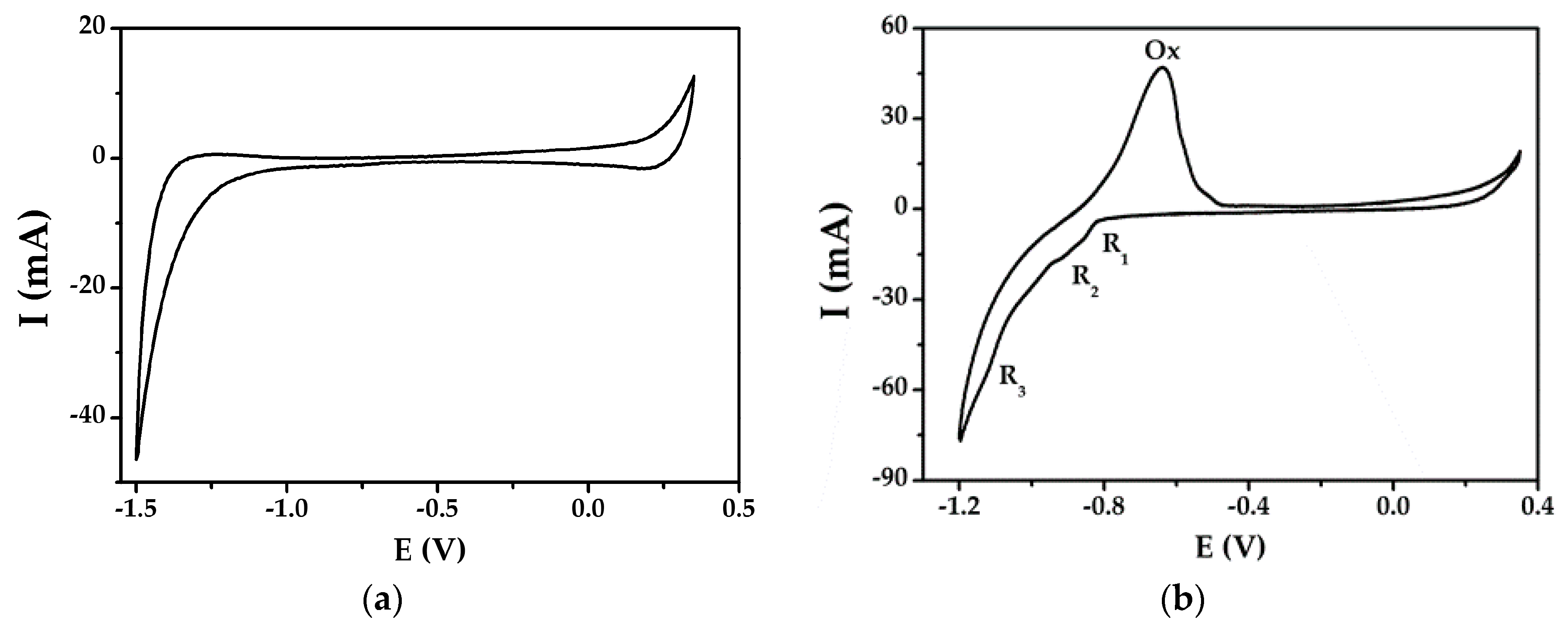
The voltammogram of the NaCl-KCl-Na
2MoO
4 melt, recorded with the molybdenum cathode, is shown in
Figure 1a. It has the same form as the NaCl–KCl melt, since MoO
42− ions are characterized by a more negative discharge potential than Na
+ and K
+ cations, and they are electrochemically inactive in an equimolar mixture of sodium and potassium chlorides [
22].
The voltammogram of the NaCl-KCl-Li
2CO
3-Na
2MoO
4 melt, recorded with the molybdenum cathode, is shown in
Figure 1b.
In the cathodic half-cycle, it has three waves R1, R2, and R3, and in the anodic half-cycle, there is only one Ox wave. Potentiostatic electrolysis at potentials of the R1, R2, and R3 waves led, according to the results of X-ray diffraction (XRD) analysis, to the formation of Mo2C. The single wave (Ox) at anodic polarization confirms the formation of only one product in the course of electrolysis. The cathodic current density for the process in the region of potentials of the R1 wave is low, which is due to low concentration of electroactive carbon-containing species. The R1 wave corresponds to the discharge of CO2 and is described by electrode Reaction (1) complicated by the preceding chemical Reaction (2). The R2 wave corresponds to the discharge of carbonate ions according to Reaction (3).
The electrode process at joint electroreduction of CO
32− and MoO
42− with the formation of Mo
2C can be described in the general form as follows:
Note that the discharge of MoO42− ions becomes possible due to the appearance of lithium cations in the melt, which shift the potential of the discharge of molybdate ions to the positive region. The use of different electrolysis regimes led to the formation of a single product at the cathode-molybdenum semi-carbide (Mo2C).
3.2. X-Ray Diffraction (XRD) Analysis
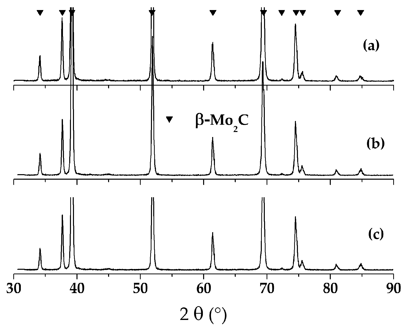
In all cases, molybdenum semi-carbide with a hexagonal crystal lattice (JCPDS card No. 35-0787) from the NaCl-KCl-Li
2CO
3 (1.5 wt.%)-Na
2MoO
4 (8.0 wt.%) melt was obtained (see
Figure 2). The formation of Mo
2C with a hexagonal lattice in the process of electrochemical synthesis occurs due to specific conditions (electric field, double layer and high temperature) of the electrocrystallization process.
3.3. Microstructure of Molybdenum Plates before and after Electrodeposition
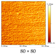
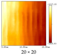
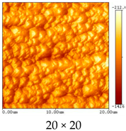
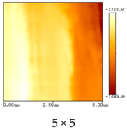
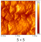
The roughness (
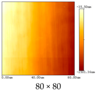
Ra–the average profile arithmetic deviation) of the initial molybdenum substrates measured on a profilometer was 0.06–0.15 µm. The roughness values of the substrates obtained by AFM (see
Table 1) are consistent with the values obtained by a standardized method using a profilometer.
However, they cannot completely correspond to each other as calculated, without taking into account the baseline length. However, these data are important because they reflect the surface relief at a more subtle level.
The data in
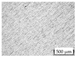
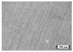
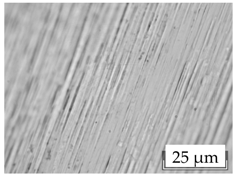
Table 1 show that the parameters of surface roughness are very different depending on the measured area, and the main contribution to the roughness values introduces the transverse direction. The microstructure of the molybdenum plate cross-section after etching is shown in
Figure 3.
As can be seen from the images obtained using an optical and atomic force microscope, the initial molybdenum substrates had a rolled structure with longitudinal deformation bands (see
Table 2).
The roughness (
Ra) of the Mo
2C coatings on molybdenum, determined using a profilometer, was 0.06–0.35 μm. After electroplating, the molybdenum semi-carbide coating had roughness values of the same order in different directions, but the longitudinal profile of the sample was already becoming more prominent than the transverse one (
Table 1). This was due to the “overgrowth” cathodic deposit rolled strips and forming a coarse deposit in the longitudinal direction (
Figure 4).
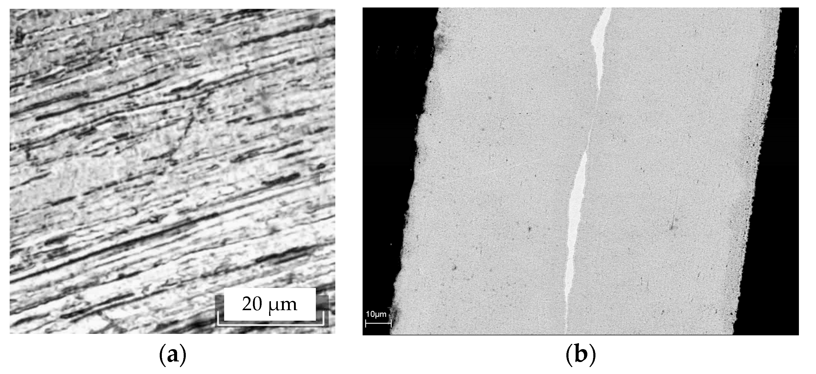
After preparing cross-section, a molybdenum substrate was often delaminated (
Figure 4a). After electrolysis molybdenum plate thickness increased by 40 microns. On a cross-section, the fine-dispersed type homogeneous structure was observed with residual located in the center of the thin section in the form of initial molybdenum elongated “islands” (
Figure 4b). The width of the “islands” did not exceed 5 μm and the presence of a diffusion zone between the substrate and the coating was not established.
3.4. Microstructure of Goffered Molybdenum Plates before and after Electrodeposition
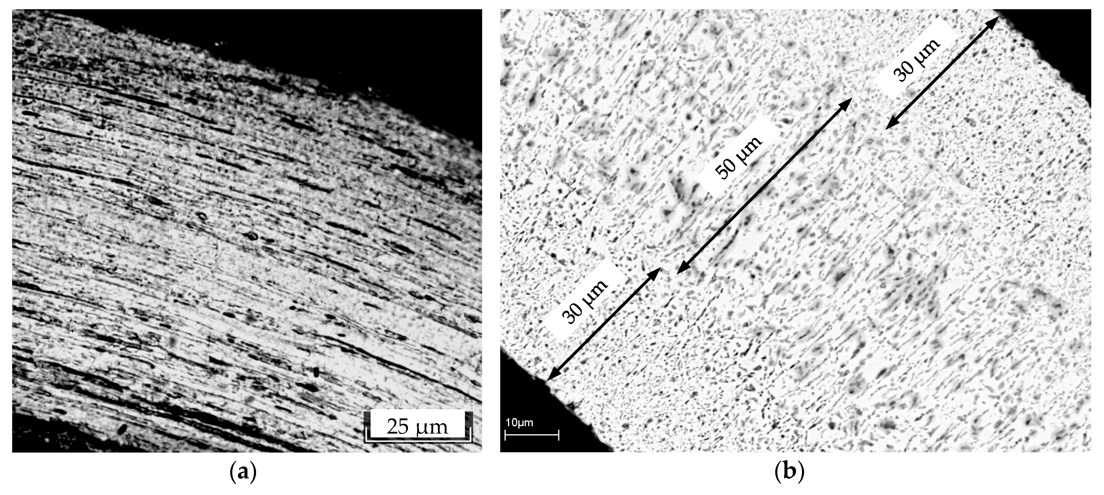
It should be noted that during preparation of the cross-section, the goffered plate did not stratify, which is associated with deformation of the obtained plate during corrugation (
Figure 5a). In the case of goffered samples, a radical change in the structure was also observed, since prior to electrodeposition the structural elements were predominantly longitudinal (rolled strip, less than 1 μm thick), then after the synthesis of the coating it became transverse (
Figure 5b).
The cross-section consists of two external zones (30 μm + 30 μm) and an internal zone 50 μm thick (
Figure 5b). XRD of goffered and crushed plates shows the presence of only one phase of molybdenum semi-carbide, and therefore the zones differ only in structure. Full carburization of the goffered plate was confirmed by microanalysis. After deposition of the coating, the sample thickness became 110 μm.
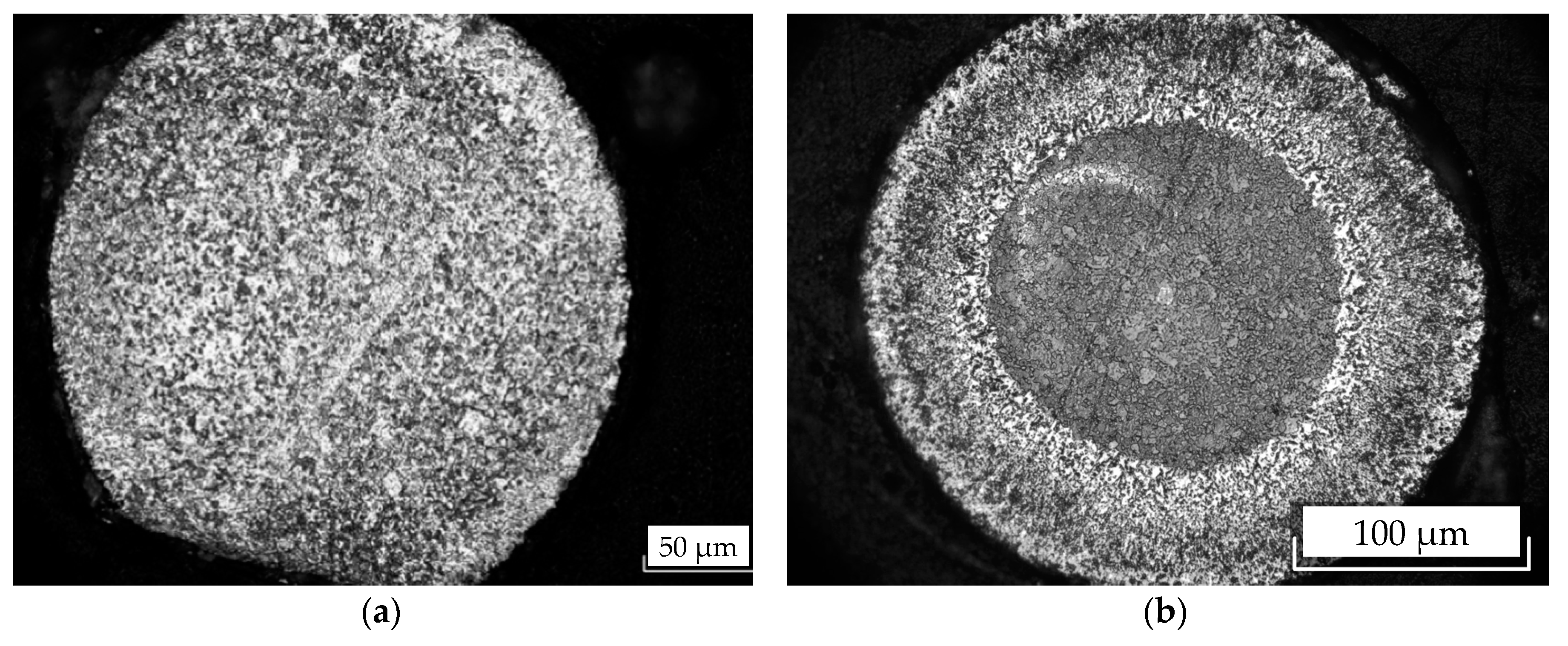
3.5. Microstructure of Molybdenum Wire before and after Electrodeposition
The microstructure of the cross-section of the original 250 µm thick molybdenum wire is shown in
Figure 6a. After electrolysis, the thickness of the samples reached 270–280 µm, i.e., the increase is 20–30 µm. The central zone with a diameter of 160 μm did not change its structure and the external zone with dimensions of 60–70 μm was radially directed and similar to the structures of the flat sample and the outer zones of the goffered plate (
Figure 6b). On a thin section, a small layer several microns thick was also observed at the interface of molybdenum/molybdenum carbide, which has a finely dispersed structure.
3.6. Molybdenum Substrate Behavior during Mo2C Electrochemical Synthesis and Its Impact on the Deposit Microstucture
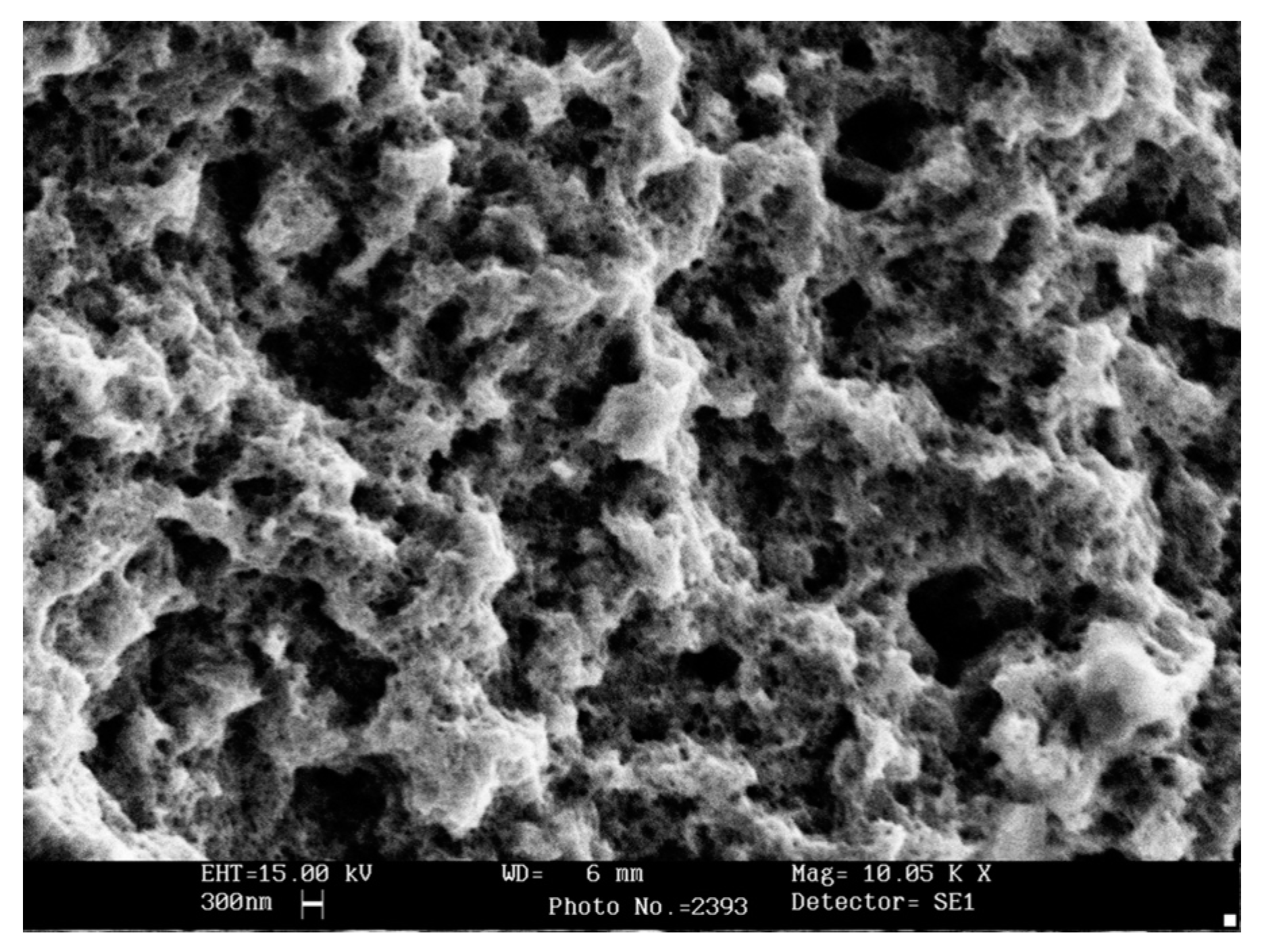
A common feature of all molybdenum products is the reduction of the substrate thickness during the electrochemical synthesis of Mo
2C. Moreover, an increase of the synthesis time led to a greater decrease of molybdenum substrate thickness. One explanation for this decrease may be the interaction of molybdenum with electrolyte used for electrochemical synthesis. Indeed, Mo
2C coating is a porous layer (see
Figure 7), which could not prevent a metal–salt reaction.
There is an equilibrium known in melts containing molybdate ions [
23,
24]:
In turn, dimolybdate ions can interact with molybdenum by the reaction [
25]:
The aforementioned interaction mechanism is one possible cause of the reduction in substrate thickness, and molybdenum substrate behavior during deposition of Mo2C coatings from the NaCl-KCl-Na2MoO4-Li2CO3 melt requires further study.
Another important result of this work is the conclusion about the influence of the substrate shape on the cathodic structure of deposit. Thus, the Mo
2C coating on a flat plate is more dense (see
Figure 4b), and in a goffered plate (see
Figure 5b) and wire (see
Figure 6b) carbide layers have a similar morphology and looser cathodic deposits.
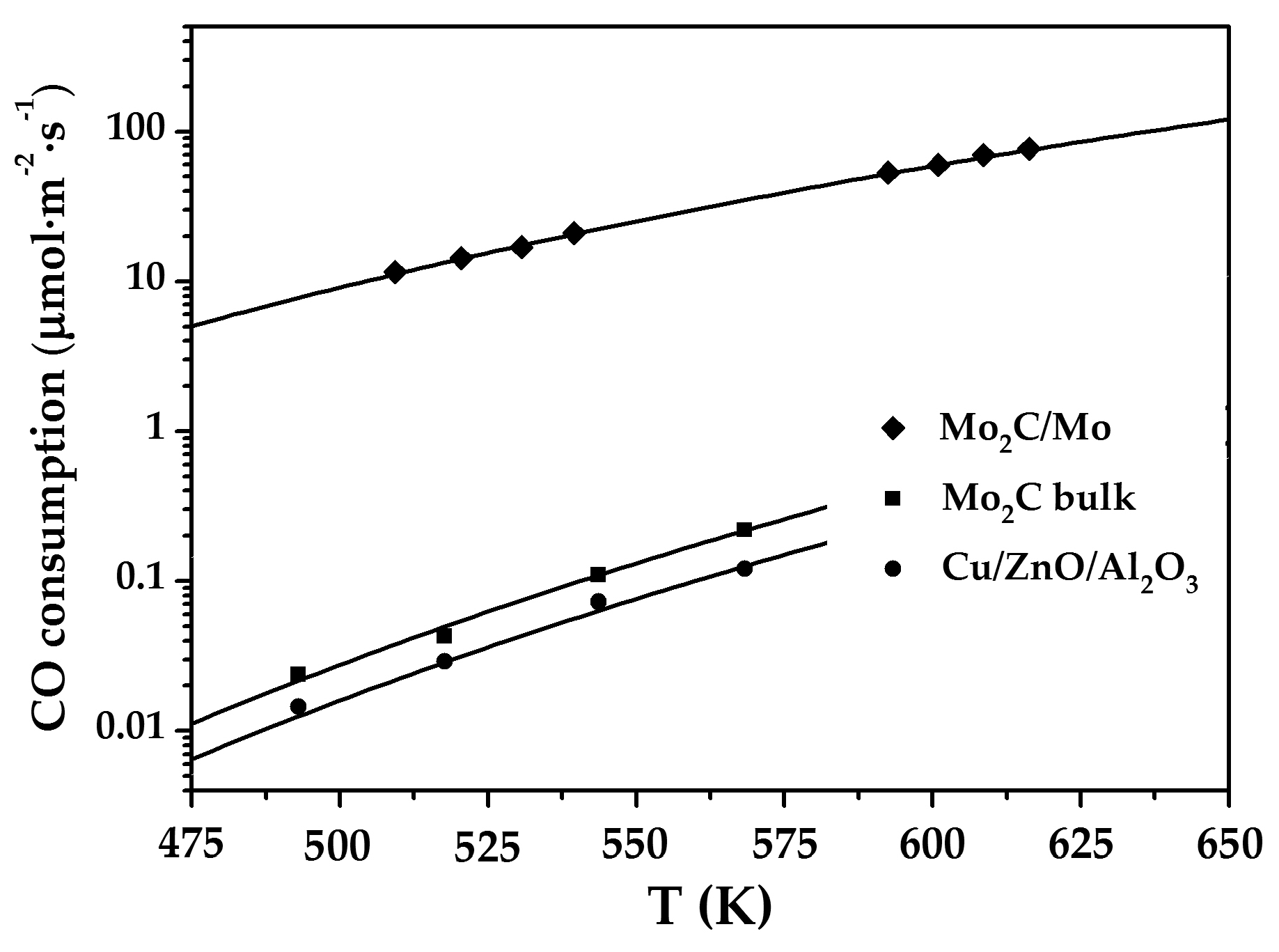
Obtained coatings were tested as a catalyst for the water–gas shift reaction:
The steady-state reaction rates for the Mo
2C/Mo coatings were higher than those for the bulk Mo
2C [
4] and commercial Cu/ZnO/Al
2O
3 catalysts over the temperature range explored (
Figure 8). The catalytic activity is enhanced by at least three orders of magnitude compared to that of the bulk Mo
2C phase if molybdenum carbides are present as a thin submicron layer on a molybdenum substrate. The methanation reaction was completely suppressed in the whole temperature range studied on the Mo
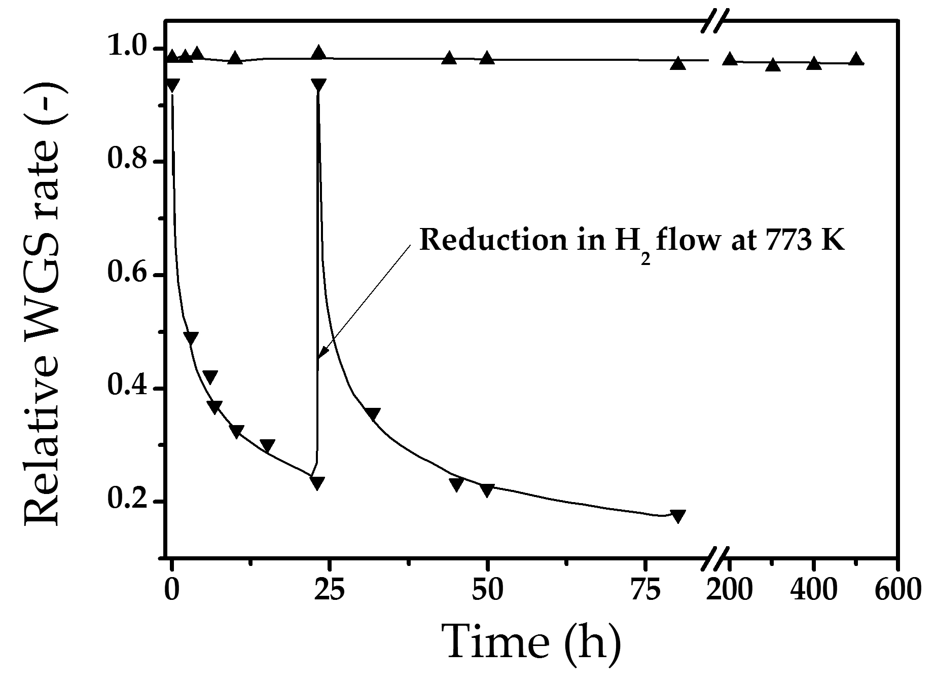
2C/Mo coatings. The catalytic activity remained constant during 500 h on-stream (
Figure 9). The coatings were also stable during the thermal cycling, while the activity of commercial catalysts tends to decrease with time.
Using articles of different shape with the Mo
2C coatings based on the mathematical model and the thermodynamic parameters calculation, a countercurrent microstructured reactor–heat exchanger was designed [
25].
4. Conclusions
Molybdenum semi-carbide coatings with a hexagonal crystal lattice on various configurations molybdenum substrates in the NaCl-KCl-Li2CO3 (1.5 wt.%)-Na2MoO4 (8.0 wt.%) melt were obtained.
A mechanism for the interaction of molybdenum with molten salt in the electrochemical synthesis process leading to a decrease in the thickness of molybdenum substrates was proposed.
The effect of the molybdenum substrate shape on the microstructure of the Mo2C coating was studied. It has been established that in the goffered plates and wire, the layers of molybdenum semi-carbide have a similar morphology and looser cathodic deposits in comparison with the Mo2C coating on a flat plate.
It was determined that the molybdenum carbide coatings on a molybdenum substrate (Mo2C/Mo) show a catalytic activity in the water–gas shift reaction by at least three orders of magnitude higher than that of the bulk Mo2C phase. The catalytic activity remained constant during 500 h for the water–gas shift reaction.
Author Contributions
Investigation, A.D.; Supervision, S.K.; Visualization, O.M.; Writing–original draft, A.D.; Writing–review & editing, S.K.
Funding
This research received no external funding.
Conflicts of Interest
The authors declare no conflict of interest.
References
- Aoki, Y.; Tominaga, H.; Nagai, M. Hydrogenation of CO on molybdenum and cobalt molybdenum carbide catalysts—Mass and infrared spectroscopy studies. Catal. Today 2013, 215, 169–175. [Google Scholar] [CrossRef]
- Setthapun, W.; Bej, S.K.; Thompson, L.T. Carbide and nitride supported methanol steam reforming catalysts: Parallel synthesis and high throughput screening. Top. Catal. 2008, 49, 73–80. [Google Scholar] [CrossRef]
- Lausche, A.C.; Schaidle, J.A.; Thompson, L.T. Understanding the effects of sulfur on Mo2C and Pt/Mo2C catalysts: Methanol steam reforming. Appl. Catal. A 2011, 401, 29–36. [Google Scholar] [CrossRef]
- Patt, J.; Moon, D.; Phillips, C.; Thompson, L. Molybdenum carbide catalysts for water-gas shift. Catal. Lett. 2000, 65, 193–195. [Google Scholar] [CrossRef]
- Schweitzer, N.M.; Schaidle, J.A.; Ezekoye, O.K.; Pan, X.; Linic, S.; Thompson, L.T. High activity carbide supported catalysts for water gas shift. J. Am. Chem. Soc. 2011, 133, 2378–2381. [Google Scholar] [CrossRef] [PubMed]
- Frauwallner, M.L.; López-Linares, F.; Lara-Romero, J.; Scott, C.E.; Ali, V.; Hernández, E.; Pereira-Almao, P. Toluene hydrogenation at low temperature using a molybdenum carbide catalyst. Appl. Catal. A 2011, 394, 62–70. [Google Scholar] [CrossRef]
- Hou, R. Replacing precious metals with carbide catalysts for hydrogenation reactions. In Catalytic and Process Study of the Selective Hydrogenation of Acetylene and 1,3-Butadiene; Springer: Singapore, 2017; pp. 89–106. [Google Scholar]
- Ren, H.; Yu, W.; Salciccioli, M.; Chen, Y.; Huang, Y.; Xiong, K.; Vlachos, D.G.; Chen, J.G. Selective hydrodeoxygenation of biomass-derived oxygenates to unsaturated hydrocarbons using molybdenum carbide catalysts. ChemSusChem 2013, 6, 798–801. [Google Scholar] [CrossRef]
- Porosoff, M.D.; Yang, X.; Boscoboinik, J.A.; Chen, J.G. Molybdenum carbide as alternative catalysts to precious metals for highly selective reduction of CO2 to CO. Angew. Chem. 2014, 126, 6823–6827. [Google Scholar] [CrossRef]
- Kojima, R.; Aika, K.I. Molybdenum nitride and carbide catalysts for ammonia synthesis. Appl. Catal. A 2001, 219, 141–147. [Google Scholar] [CrossRef]
- Moon, D.J.; Screekumar, K.; Lee, S.D.; Lee, B.G.; Kim, H.S. Studies on gasoline fuel processor system for fuel-cell powered vehicles application. Appl. Catal. A 2001, 215, 1–9. [Google Scholar] [CrossRef]
- Wang, X.H.; Hao, H.L.; Zhang, M.H.; Li, W.; Tao, K.Y. Synthesis and characterization of molybdenum carbides using propane as carbon source. J. Solid State Chem. 2006, 179, 538–543. [Google Scholar] [CrossRef]
- Gillet, E.; Chiarena, J.C.; Gilet, M. Décomposition thermique du monoxide de carbone sur une surface de molybdène: Formation de couches superficielles de carbone et de carbure. Surf. Sci. 1976, 55, 126–140. [Google Scholar] [CrossRef]
- Campbell, I.E.; Powell, C.F.; Nowicki, D.H.; Gonser, B.W. The vapor-phase deposition of refractory materials I. General conditions and apparatus. J. Electrochem. Soc. 1949, 96, 318–333. [Google Scholar] [CrossRef]
- Malyshev, V.; Gab, A.; Gaune-Escard, M. Initial stages of nucleation of molybdenum and tungsten carbide phases in tungstate–molybdate–carbonate melts. J. Appl. Electrochem. 2008, 38, 315–320. [Google Scholar] [CrossRef]
- Topor, D.C.; Selman, J.R. Molybdenum carbide coatings electrodeposited from molten fluoride bath preparation of coherent coatings. J. Electrochem. Soc. 1988, 135, 384–387. [Google Scholar] [CrossRef]
- Malyshev, V.V.; Gab, A.I.; Pisanenko, A.D.; Soloviev, V.V.; Chernenko, L.A. Electrodeposition of tungsten and molybdenum carbide onto the surfaces of disperse dielectric and semiconductor materials. Int. J. Electrochem. Sci. 2014, 45, 51–56. [Google Scholar] [CrossRef]
- Okada, T.; Fukuoka, K.; Arata, Y.; Yonezawa, S.; Kiyokawa, H.; Takashima, M. Tungsten carbide coating on diamond particles in molten mixture of Na2CO3 and NaCl. Diamond Relat. Mater. 2015, 52, 11–17. [Google Scholar] [CrossRef]
- Zhang, K.; Shi, Z.; Zhang, X.; Zhang, Z.; Ge, B.; Xia, H.; Guo, Y.; Oiao, G. Molten salt synthesis of continuous tungsten carbide coatings on graphite flakes. Ceram. Int. 2017, 43, 8089–8097. [Google Scholar] [CrossRef]
- Malyshev, V.V.; Gab, A.I.; Shakhnin, D.; Donath, C.; Neacsu, E.I.; Popescu, A.M.; Constantin, V. High temperature ionic liquids electrosynthesis of Mo2C protective coatings on diamond, boron nitride, silicon and boron carbide. Rev. Chim. (Bucharest) 2018, 69, 544–548. [Google Scholar]
- Graves, A.D.; Inman, D. Adsorption and the differential capacitance of the electrical double-layer at platinum/halide metal interfaces. Nature 1965, 208, 481–482. [Google Scholar] [CrossRef]
- Malyshev, V.V.; Novoselova, I.A.; Kushkhov, H.B.; Shapoval, V.I. High-temperature electrochemical synthesis: A new method for synthesizing molybdenum and tungsten carbide powders. Russ. J. Inorg. Chem. 1997, 42, 469–475. [Google Scholar]
- Shunailov, A.F.; Baraboshkin, A.N.; Martynov, V.A. Anodic dissolution of molybdenum in chloride-molybdate melt. Tr. Inst. Elektrokhim. Akad. Nauk SSSR 1969, 13, 40–48. (In Russian) [Google Scholar]
- Baraboshkin, A.N. Electrocrystallization from Molten Salts; Nauka Publishers: Moscow, Russia, 1976; p. 280. [Google Scholar]
- Dubrovskiy, A.R.; Rebrov, E.V.; Kuznetsov, S.A.; Schouten, J.C. A microstructured reactor/heat-exchanger for the water-gas shift reaction operated in the 533–673 K range. Catal. Today 2009, 147, S198–S203. [Google Scholar] [CrossRef]
Figure 1.
Cyclic voltammograms recorded on a molybdenum electrode in the melts: (a) NaCl-KCl-Na2MoO4 (CNa2MoO4 = 3.58 × 10⁻⁴ mol·cm−3), and (b) NaCl-KCl-Li2CO3-Na2MoO4 (CLi2CO3 = 2.8 × 10⁻⁴ mol·cm−3, CNa2MoO4 = 5.47 × 10⁻⁴ mol·cm−3). Electrode surface area 0.238 cm2, potential sweep rate 0.1 V·s−1, temperature 1023 K, platinum quasi-reference electrode.
Figure 2.
X-ray diffraction (XRD) patterns of molybdenum carbide on molybdenum substrates with different shapes: (a) straight plate, (b) goffered plate, (c) wire. NaCl-KCl-Li2CO3 (1.5 wt.%)-Na2MoO4 (8.0 wt.%) melt, temperature 1123 K, current density 5 mA·cm−2.
Figure 2.
X-ray diffraction (XRD) patterns of molybdenum carbide on molybdenum substrates with different shapes: (a) straight plate, (b) goffered plate, (c) wire. NaCl-KCl-Li2CO3 (1.5 wt.%)-Na2MoO4 (8.0 wt.%) melt, temperature 1123 K, current density 5 mA·cm−2.
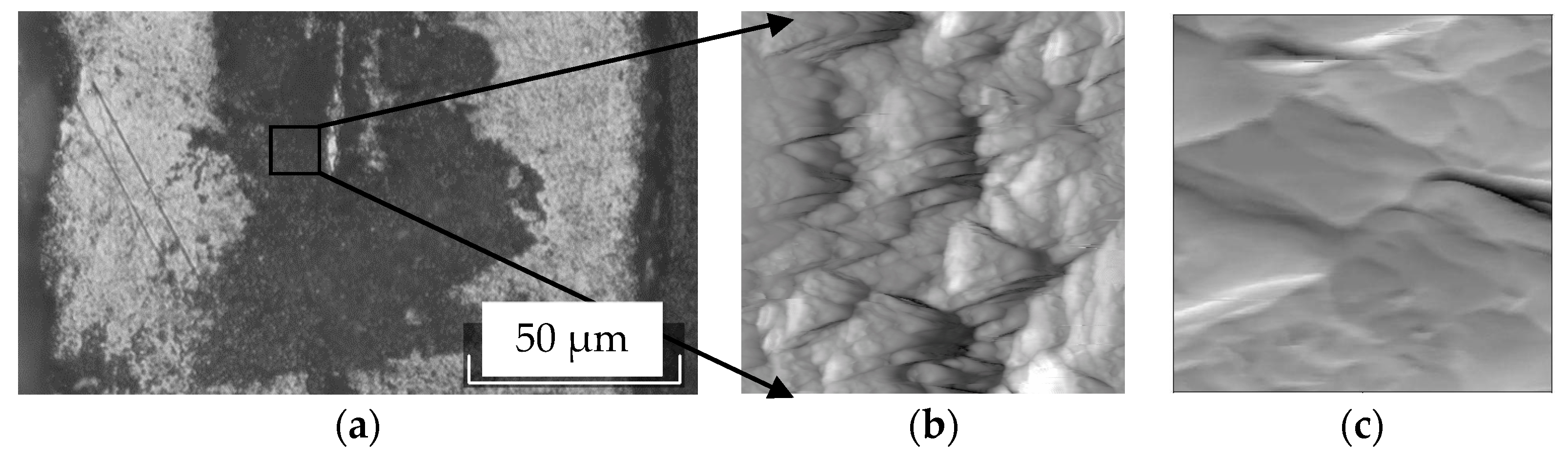
Figure 3.
Microimage of the original molybdenum plate cross-section after etching: (a) optical microscope, (b) AFM area 5.93 µm × 5. 93 µm, (c) AFM area 1.14 µm × 1.14 µm.
Figure 3.
Microimage of the original molybdenum plate cross-section after etching: (a) optical microscope, (b) AFM area 5.93 µm × 5. 93 µm, (c) AFM area 1.14 µm × 1.14 µm.
Figure 4.
Microimages of a flat molybdenum plate cross-section: (a) an original substrate after cross-section preparation and its etching; (b) after electrolysis.
Figure 4.
Microimages of a flat molybdenum plate cross-section: (a) an original substrate after cross-section preparation and its etching; (b) after electrolysis.
Figure 5.
Microimages of a goffered molybdenum plate cross-section: (a) an original substrate after cross-section preparation and its etching; (b) after electrolysis.
Figure 5.
Microimages of a goffered molybdenum plate cross-section: (a) an original substrate after cross-section preparation and its etching; (b) after electrolysis.
Figure 6.
Microimages of a molybdenum wire cross-section: (a) an original substrate after cross-section preparation and its etching; (b) after electrolysis.
Figure 6.
Microimages of a molybdenum wire cross-section: (a) an original substrate after cross-section preparation and its etching; (b) after electrolysis.
Figure 7.
The morphology of the Mo2C coating on a molybdenum substrate obtained from the NaCl-KCl-Li2CO3 (1.5 wt.%)-Na2MoO4 (8.0 wt.%) melt. Temperature 1123 K, current density 5 mA·cm−2.
Figure 7.
The morphology of the Mo2C coating on a molybdenum substrate obtained from the NaCl-KCl-Li2CO3 (1.5 wt.%)-Na2MoO4 (8.0 wt.%) melt. Temperature 1123 K, current density 5 mA·cm−2.
Figure 8.
Water–gas shift reaction rate as a function of temperature on different catalysts. Reaction conditions: pCO = 0.003 atm, pH2O = 0.013 atm, pH2 = 0.4 atm, balance-He. Total flow: 50 cm3·min−1 (STP).
Figure 8.
Water–gas shift reaction rate as a function of temperature on different catalysts. Reaction conditions: pCO = 0.003 atm, pH2O = 0.013 atm, pH2 = 0.4 atm, balance-He. Total flow: 50 cm3·min−1 (STP).
Figure 9.
Stability of Mo
2C/Mo composition (▲) compared with bulk Mo
2C (▼) under water–gas shift (WGS) reaction conditions (same in
Figure 8).
Figure 9.
Stability of Mo
2C/Mo composition (▲) compared with bulk Mo
2C (▼) under water–gas shift (WGS) reaction conditions (same in
Figure 8).
Table 1.
Roughness values obtained using an atomic force microscope (AFM).
Table 1.
Roughness values obtained using an atomic force microscope (AFM).
| Sample | Measurement Area, µm | Roughness Values, µm |
|---|
| By Line | By Area |
|---|
| Along the Sample | Across the Sample |
|---|
| Substrate | 80 × 80 | 0.13 | 0.73 | 0.75 |
| 20 × 20 | 0.06 | 0.27 | 0.27 |
| 5 × 5 | 0.01 | 0.1 | 0.1 |
| Coated | 80 × 80 | 0.31 | 0.19 | 0.28 |
| 20 × 20 | 0.25 | 0.18 | 0.2 |
| 5 × 5 | 0.12 | 0.14 | 0.15 |
Table 2.
Micrographs of a flat molybdenum plate before and after the electrochemical synthesis of the Mo2C coating obtained on optical and atomic force microscopes.
© 2018 by the authors. Licensee MDPI, Basel, Switzerland. This article is an open access article distributed under the terms and conditions of the Creative Commons Attribution (CC BY) license (http://creativecommons.org/licenses/by/4.0/).


