Effects of Island-Coated PVdF-HFP Composite Separator on the Performance of Commercial Lithium-ion Batteries

Abstract
1. Introduction
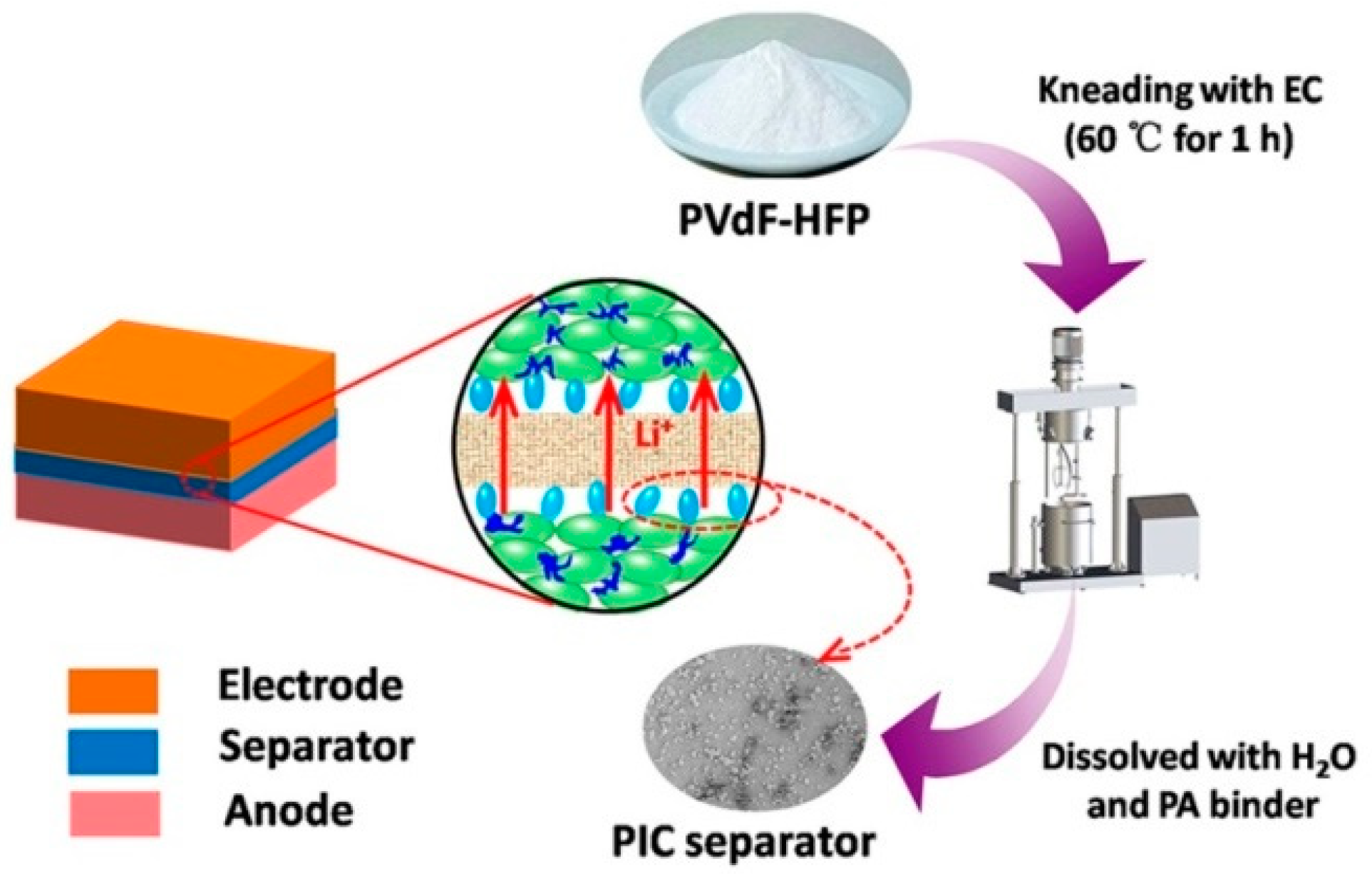
2. Materials and Methods
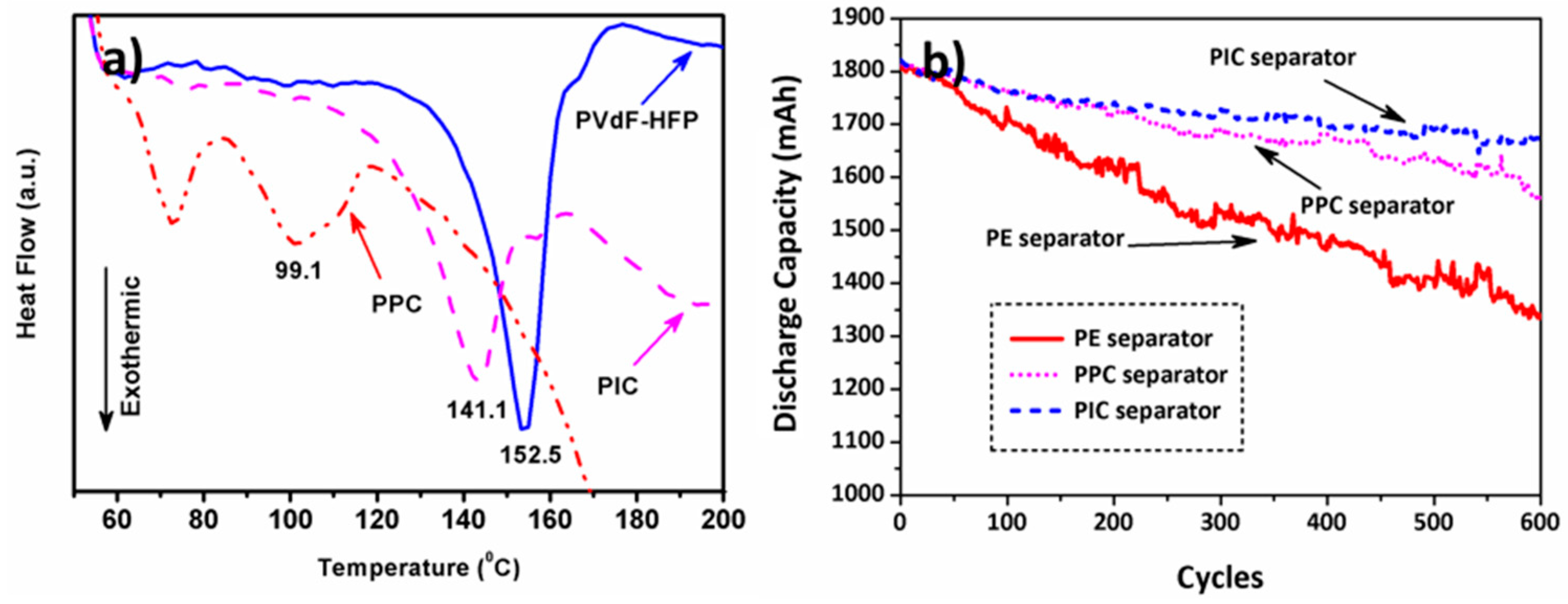
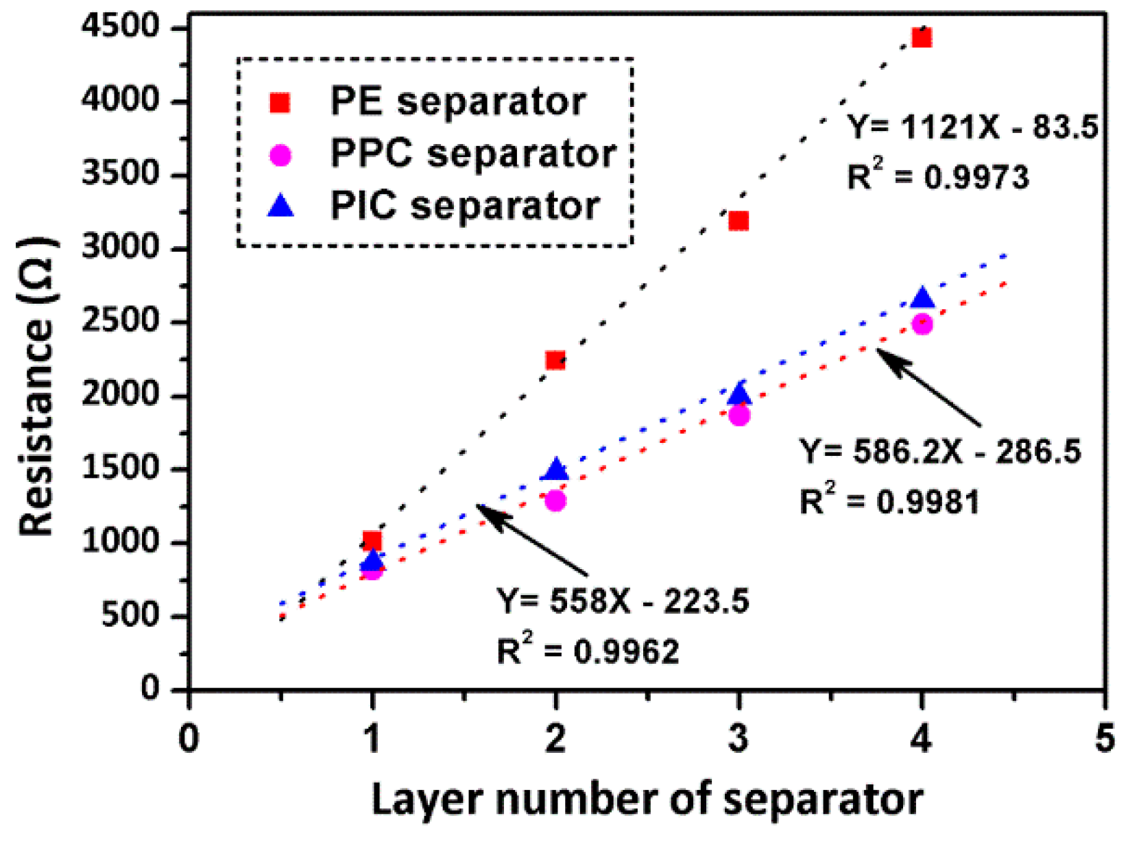
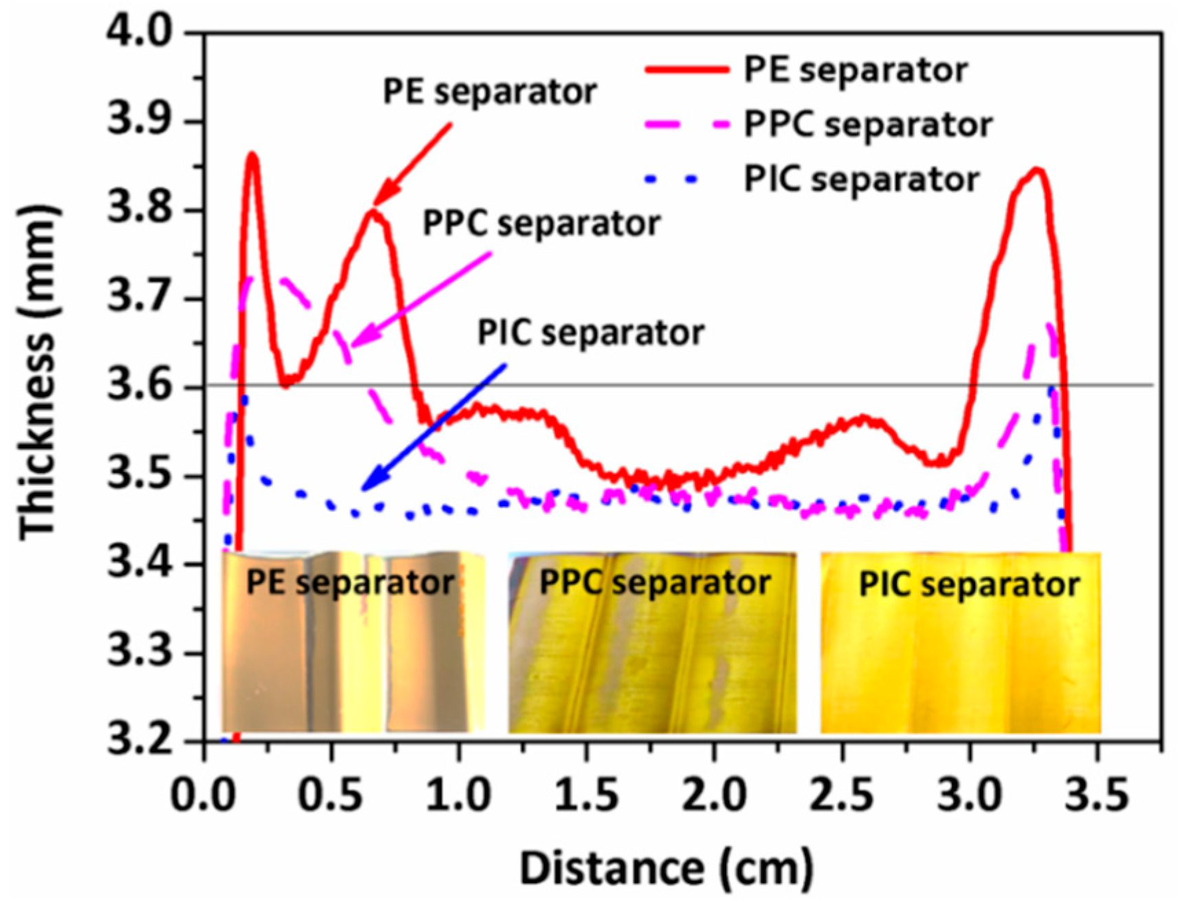
3. Results and Discussion
4. Conclusions
Author Contributions
Funding
Conflicts of Interest
References
- Xu, Q.; Kong, Q.; Liu, Z.; Zhang, J.; Wang, X.; Liu, R.; Yue, L.; Cui, G. Polydopamine-coated cellulose microfibrillated membrane as high performance lithium-ion battery separator. RSC Adv. 2014, 4, 7845–7850. [Google Scholar] [CrossRef]
- Rasoulis, M.; Vernardou, D. Electrodeposition of vanadium oxides at room temperature as cathodes in lithium-ion batteries. Coatings 2017, 7, 100. [Google Scholar] [CrossRef]
- Choi, N.S.; Han, J.G.; Ha, S.Y.; Park, I.; Back, C.K. Recent advances in the electrolytes for interfacial stability of high-voltage cathodes in lithium-ion batteries. RSC Adv. 2015, 5, 2732–2748. [Google Scholar] [CrossRef]
- Zier, M.; Scheiba, F.; Oswald, S.; Thomas, J.; Goers, D.; Scherer, T.; Klose, M.; Ehrenberg, H.; Eckert, J. Lithium dendrite and solid electrolyte interphase investigation using OsO4. J. Power Sources 2014, 266, 198–207. [Google Scholar] [CrossRef]
- Kim, G.T.; Passerini, S.; Carewska, M.; Appetecchi, G. Ionic liquid-based electrolyte membranes for medium-high temperature lithium polymer batteries. Membranes 2018, 8, 41. [Google Scholar] [CrossRef] [PubMed]
- Lin, D.; Zhuo, D.; Liu, Y.; Cui, Y. All-integrated bifunctional separator for Li dendrite detection via novel solution synthesis of a thermostable polyimide separator. J. Am. Chem. Soc. 2016, 138, 11044–11050. [Google Scholar] [CrossRef] [PubMed]
- Xu, X.; Wang, S.; Wang, H.; Hu, C.; Jin, Y.; Liu, J.; Yan, H. Recent progresses in the suppression method based on the growth mechanism of lithium dendrite. J. Energy Chem. 2018, 27, 513–527. [Google Scholar] [CrossRef]
- Zhang, Y.; Qian, J.; Xu, W.; Russell, S.M.; Chen, X.; Nasybulin, E.; Bhattacharya, P.; Engelhard, M.; Mei, D.; Cao, R.; et al. Dendrite-free lithium deposition with self-aligned nanorod structure. Nano Lett. 2014, 14, 6889–6896. [Google Scholar] [CrossRef] [PubMed]
- Lee, H.; Alcoutlabi, M.; Toprakci, O.; Xu, G.; Watson, J.V.; Zhang, X. Preparation and characterization of electrospun nanofiber-coated membrane separators for lithium-ion batteries. J. Solid State Electrochem. 2014, 18, 2451–2458. [Google Scholar] [CrossRef]
- Zhang, S.S.; Xu, K.; Jow, T.R. An inorganic composite membrane as the separator of Li-ion batteries. J. Power Sources 2005, 140, 361–364. [Google Scholar] [CrossRef]
- David, L.; Shareef, K.M.; Abass, M.A.; Singh, G. Three-dimensional polymer-derived ceramic/graphene paper as a Li-ion battery and supercapacitor electrode. RSC Adv. 2016, 6, 53894–53902. [Google Scholar] [CrossRef]
- Tu, Z.; Kambe, Y.; Lu, Y.; Archer, L.A. Nanoporous polymer-ceramic composite electrolytes for lithium metal batteries. Adv. Energy Mater. 2014, 4, 1300654. [Google Scholar] [CrossRef]
- Wu, H.; Zhuo, D.; Kong, D.; Cui, Y. Improving battery safety by early detection of internal shorting with a bifunctional separator. Nat. Commun. 2014, 5, 5193. [Google Scholar] [CrossRef] [PubMed]
- Li, N.; Wei, W.; Xie, K.; Tan, J.; Zhang, L.; Luo, X.; Yuan, K.; Song, Q.; Li, H.; Shen, C.; et al. Suppressing dendritic lithium formation using porous media in lithium metal-based batteries. Nano Lett. 2018, 18, 2067–2073. [Google Scholar] [CrossRef] [PubMed]
- Dong, Z.; Zhang, Q.; Yu, C.; Peng, J.; Ma, J.; Ju, X.; Zhai, M. Effect of ionic liquid on the properties of poly(vinylidene fluoride)-based gel polymer electrolytes. Ionics 2013, 19, 1587–1593. [Google Scholar] [CrossRef]
- Sousa, R.E.; Kundu, M.; Gören, A.; Silva, M.M.; Liu, L.; Costa, C.M.; Lanceros-Mendez, S. Poly(vinylidene fluoride-co-chlorotrifluoroethylene) (PVDF-CTFE) lithium-ion battery separator membranes prepared by phase inversion. RSC Adv. 2015, 5, 90428–90436. [Google Scholar] [CrossRef]
- Wu, F.; Feng, T.; Bai, Y.; Wu, C.; Ye, L.; Feng, Z. Preparation and characterization of solid polymer electrolytes based on PHEMO and PVDF-HFP. Solid State Ion. 2009, 180, 677–680. [Google Scholar] [CrossRef]
- Bandara, T.M.W.J.; Weerasinghe, A.M.J.S.; Dissanayake, M.A.K.L.; Senadeera, G.K.R.; Furlani, M.; Albinsson, I.; Mellander, B.E. Characterization of poly (binylidene fluoride-co-hexafluoropropylene) (PVdF-HFP) nanofiber membrane based quasi solid electrolytes and their application in a dye sensitized solar cell. Electrochim. Acta 2018, 266, 276–283. [Google Scholar] [CrossRef]
- Wang, S.; Ajji, A.; Guo, S.; Xiong, C. Preparation of microporous polypropylene/titanium dioxide composite membranes with enhanced electrolyte uptake capability via melt extruding and stretching. Polymers 2017, 9, 110. [Google Scholar] [CrossRef]
- Santhanagopalan, S.; Zhang, Z.M. Separators for lithium-ion batteries. In Lithium-Ion Batteries: Advanced Materials and Technologies; Yuan, X., Liu, H., Zhang, J., Eds.; CRC Press: Boca Raton, FL, USA, 2011. [Google Scholar]
- Romanyuk, K.; Costa, C.M.; Luchkin, S.Y.; Kholkin, A.L.; Lanceros-Méndez, S. Giant electric-field-induced strain in PVDF-based battery separator membranes probed by electrochemical strain microscopy. Langmuir 2016, 32, 5267–5276. [Google Scholar] [CrossRef] [PubMed]
- Gao, K.; Hu, X.; Dai, C.; Yi, T. Crystal structures of electrospun PVdF membranes and its separator application for rechargeable lithium metal cells. Mater. Sci. Eng. B 2006, 131, 100–105. [Google Scholar] [CrossRef]
- Seidel, S.M.; Jeschke, S.; Vettikuzha, P.; Wiemhofer, H.D. PVDF-HFP/ether-modified polysiloxane membranes obtained via airbrush spraying as active separators for application in lithium ion batteries. Chem. Commun. 2015, 51, 12048–12051. [Google Scholar] [CrossRef] [PubMed]
- Romanyuk, K.; Costa, C.M.; Luchkin, S.Y.; Kholkin, A.L.; Lanceros-Méndez, S. Giant electric-field-induced strain in PVDF-based battery separator membranes probed by electrochemical strain microscopy. Langmuir 2016, 32, 5267–5276. [Google Scholar] [CrossRef] [PubMed]
- Zhang, N.; Tang, H. Dissecting anode swelling in commercial lithium-ion batteries. J. Power Sources 2012, 218, 52–55. [Google Scholar] [CrossRef]
- Shi, B.; Kang, Y.; Xie, H.; Song, H.; Zhang, Q. In situ measurement and experimental analysis of lithium mass transport in graphite electrodes. Electrochim. Acta 2018, 284, 142–148. [Google Scholar] [CrossRef]
- Liu, Z.; Zhou, J.; Chen, B.; Zhu, J. Interaction between dislocation mechanics on diffusion induced stress and electrochemical reaction in a spherical lithium ion battery electrode. RSC Adv. 2015, 5, 74835–74843. [Google Scholar] [CrossRef]
- Cannarella, J.; Arnold, C.B. Stress evolution and capacity fade in constrained lithium-ion pouch cells. J. Power Sources 2014, 245, 745–751. [Google Scholar] [CrossRef]
- Chen, P.H.; Chung, D.D.L. Thermal and electrical conduction in the compaction direction of exfoliated graphite and their relation to the structure. Carbon 2014, 77, 538–550. [Google Scholar] [CrossRef]
- Darling, K.A.; Tschopp, M.A.; Roberts, A.J.; Ligda, J.P.; Kecskes, L.J. Enhancing grain refinement in polycrystalline materials using surface mechanical attrition treatment at cryogenic temperatures. Scr. Mater. 2013, 69, 461–464. [Google Scholar] [CrossRef]


| Sample | Tm (°C) | ||
|---|---|---|---|
| PVdF-HFP | 152.5 | 18.69 | 17.85 |
| PPC | 99.1 | 2.43 | 2.32 |
| PIC | 141.1 | 11.11 | 10.61 |
| Separators | Gurley Value (s/10 mL) | Electrolyte Uptake (%) | Ionic Conductivity (mS/cm) | Contact Angle (°) |
|---|---|---|---|---|
| PE | 7.8 | 62 | 0.23 | 99 |
| PPC | 14.2 | 115 | 0.98 | 75 |
| PIC | 8.0 | 130 | 0.96 | 50 |
© 2018 by the authors. Licensee MDPI, Basel, Switzerland. This article is an open access article distributed under the terms and conditions of the Creative Commons Attribution (CC BY) license (http://creativecommons.org/licenses/by/4.0/).
Share and Cite
Zhao, J.; Hu, Q.; Wang, J.; Zhang, P.; Zhu, Y.; Wu, G.; Lv, Y.; Lv, L.; Zhao, Y.; Yang, M. Effects of Island-Coated PVdF-HFP Composite Separator on the Performance of Commercial Lithium-ion Batteries. Coatings 2018, 8, 437. https://doi.org/10.3390/coatings8120437
Zhao J, Hu Q, Wang J, Zhang P, Zhu Y, Wu G, Lv Y, Lv L, Zhao Y, Yang M. Effects of Island-Coated PVdF-HFP Composite Separator on the Performance of Commercial Lithium-ion Batteries. Coatings. 2018; 8(12):437. https://doi.org/10.3390/coatings8120437
Chicago/Turabian StyleZhao, Junhua, Qin Hu, Jun Wang, Pinjie Zhang, Youliang Zhu, Guoqiang Wu, Yanwen Lv, Liang Lv, Yongjin Zhao, and Meiting Yang. 2018. "Effects of Island-Coated PVdF-HFP Composite Separator on the Performance of Commercial Lithium-ion Batteries" Coatings 8, no. 12: 437. https://doi.org/10.3390/coatings8120437
APA StyleZhao, J., Hu, Q., Wang, J., Zhang, P., Zhu, Y., Wu, G., Lv, Y., Lv, L., Zhao, Y., & Yang, M. (2018). Effects of Island-Coated PVdF-HFP Composite Separator on the Performance of Commercial Lithium-ion Batteries. Coatings, 8(12), 437. https://doi.org/10.3390/coatings8120437