Article

Effect of CeO2 on Microstructure and Properties of Cr3C2/Fe-Based Composite Coatings

College of Mechanical Engineering, North China University of Science and Technology, Tangshan 063210, China
*
Author to whom correspondence should be addressed.
Coatings 2026, 16(2), 187; https://doi.org/10.3390/coatings16020187
Submission received: 31 December 2025 / Revised: 19 January 2026 / Accepted: 23 January 2026 / Published: 2 February 2026
(This article belongs to the Section Corrosion, Wear and Erosion)

Abstract

As a critical component of scraper conveyors, the middle trough operates under harsh conditions for extended periods, making it prone to failure and thus reducing the overall service life of the equipment. To address this issue and extend its service life, this study incorporated different amounts of CeO2 into Cr3C2/Fe-based composite coatings. It investigated the effects of CeO2 on the coating’s phase composition, microstructural evolution, wear resistance and corrosion resistance. Results show that CeO2 addition did not alter the coating’s phase composition. The composition remained α-Fe, M23C6 (M: Fe, Cr) and vanadium carbides. However, CeO2 promoted the transformation from columnar grains to equiaxed grains and refined the grains. With increasing CeO2 content, the composite coating’s mechanical properties gradually improved. The Ce2 coating exhibited the highest microhardness (923.08 HV0.5), the lowest friction coefficient (0.31) and the lowest wear rate (0.00217 mm3/N·m). Its dominant wear mechanisms were abrasive wear and mild adhesive wear. In 3.5% NaCl solution, the Ce2 coating showed the highest corrosion potential (−0.82 V) and the lowest corrosion current density (2.04 × 10⁻⁶ A/cm2), indicating excellent corrosion resistance. This study provides theoretical support for preparing high-performance Cr3C2/Fe-based composite coatings. It clarifies the key mechanism by which CeO2 regulates coating properties. The developed composite coating has broad application potential due to its excellent combined wear and corrosion resistance. It can be widely used for surface strengthening of vulnerable components in mining machinery such as scraper conveyors, offering important theoretical and technical support for improving the service life of scraper conveyor middle troughs.

Graphical Abstract

1. Introduction

As core equipment for bulk material transportation in coal mining, metallurgy, building materials, and other industries, the operational reliability and stability of mining scraper conveyors directly determine the efficiency and safety of the entire production line [1,2,3]. The center trough, a critical component of scraper conveyors undertaking load-bearing and power transmission functions, plays a decisive role in the service life of the entire conveyor system [4,5,6]. Under actual operating conditions, the center trough is not only subjected to severe friction from scrapers and conveyed materials but is also eroded by hard particles (e.g., coal gangue) and corroded in humid environments. Consequently, the average service life of center troughs is typically less than six months. Frequent replacement and maintenance not only increase production costs significantly but also severely disrupt the continuity of production [7,8,9]. Therefore, developing high-quality and high-efficiency surface strengthening technologies to enhance the wear and corrosion resistance of center troughs and extend their service life has become a pressing technical imperative in the field of equipment manufacturing.
Laser cladding technology, as an advanced surface modification technique, has received extensive attention due to its prominent advantages such as excellent metallurgical bonding, low dilution rate, diverse functionalities, and controllable composition and thickness [10]. Fe-based alloys possess distinct advantages including abundant raw material sources, low cost, and excellent substrate compatibility, rendering them ideal candidates for the surface strengthening of central chutes. However, Fe-based alloy coatings fabricated by conventional techniques exhibit relatively inferior hardness and wear resistance, thus exhibiting poor adaptability to the severe service conditions of central chutes—characterized by prolonged exposure to friction, particle erosion, and corrosion in humid environments. Consequently, there is an urgent demand to enhance their comprehensive performance to withstand such complex operational scenarios. As high-performance second-phase particles, Cr3C2 ceramics can effectively integrate the mechanical properties of metals with the superior wear resistance of ceramics, endowing the composite coatings with excellent comprehensive performances [11,12,13,14]. Nevertheless, the high hardness and limited fracture toughness of ceramic particles induce significant residual stresses during the cladding process [15]. These residual stresses inevitably give rise to defects such as spalling and cracking in the coatings, which severely impairs the structural integrity of the coatings and restricts their practical application in the surface strengthening of central chutes. Rare earth elements, benefiting from their unique electronic shell structure, exert remarkable modification effects in the preparation of metallic materials and coatings. The introduction of rare earth elements into coatings can promote grain refinement, purify grain boundaries, optimize microstructure morphologies, and thereby enhance the overall performance of the coatings [16]. CeO2, a commonly used rare earth oxide, is capable of refining grains, decreasing dendrite arm spacing, purifying grain boundaries, and facilitating martensitic transformation. This not only effectively reduces defects such as cracks and pores but also improves the quality of coating formation [17]. This defect-mitigating attribute renders CeO2 a promising additive for overcoming technical bottlenecks in laser-clad, ceramic-reinforced Fe-based composite coatings. Chang et al. [18] demonstrated that Ce enhances grain boundary strength in multielement alloy coatings; CeO2 additionally refines grains and improves friction-wear properties, hardness, and toughness. Zhu et al. [19] investigated CeO2’s influence on Ni60A-WC coatings on 304 steel surfaces, finding that CeO2 optimized structure, refined grains, and elevated wear resistance (across temperatures) and corrosion resistance. These studies demonstrate the significant role of rare-earth oxides in enhancing the mechanical properties and refining the microstructure of laser-clad coatings. However, most existing research focuses solely on the performance improvement of Fe-based coatings by individual additions of CeO2 or Cr3C2 particles. Studies concerning the synergistic modification of Fe-based composite coatings via the simultaneous incorporation of CeO2 and Cr3C2 remain scarce, and the coatings developed by conventional methods still fail to meet the stringent performance requirements of scraper conveyor components.
Therefore, guided by the surface strengthening requirements for the center trough of scraper conveyors, this study fabricates Cr3C2/Fe-based composite coatings with varying CeO2 contents via laser cladding. The objectives are to determine the optimal CeO2 addition amount, design high-performance composite coatings that integrate the strengthening effects of both rare earth elements and hard particles, achieve significant performance enhancement of Q345 steel, and thereby provide a theoretical basis and technical support for extending the service life of the middle trough of scraper conveyors.

2. Materials and Methods

2.1. Experimental Materials

The experimental material selected is Q345 steel with dimensions of 100 mm × 100 mm × 10 mm as the base material, and its chemical composition is shown in Table 1. The coating material powder is a self-fluxing Fe-based alloy powder with a particle size range of 50–150 μm, and its chemical composition is presented in Table 2. The Cr3C2 powder featured a particle size of 10–50 μm, while the CeO2 powder had a particle size of 5–10 μm. All powders had a purity of greater than 99.9 wt.%. Prior to cladding, the powders were homogenized in a ball mill at 300 rpm for 4 h. Subsequently, the blended powders were dried in a vacuum oven at 200 °C for 2 h to eliminate moisture and improve the quality of the cladding layer. The initial morphologies of the powders are illustrated in Figure 1. It can be observed that the Fe-based alloy powder exhibits excellent sphericity, whereas the Cr3C2 and CeO2 powders display a flake-like morphology.

2.2. Coating Preparation

The basic principle of the laser cladding equipment used in this experiment is illustrated in Figure 2. The system comprises a TruDisk 6006 laser (TRUMPF, Ditzingen, Germany), a KUKA robotic arm (KUKA AG, Augsburg, Germany), a 6000 W disk laser (TRUMPF, Ditzingen, Germany), a cooling system, and a powder feeding system. During the laser cladding process, the laser power is set to 1850.00 W, the scanning speed is 9.00 mm/s, and the powder feeding rate is 3.85 r/min. Helium (He) was selected as the powder feeding gas, while argon (Ar) served as the shielding gas. The gas flow rate was maintained at 3 L/min to prevent damage to the components caused by powder splatter and reflection during the cladding process.

2.3. Performance Characterization

For each concentration, 5 samples with dimensions of 40 mm × 40 mm were prepared. After cladding, samples with dimensions of 10 mm × 10 mm × 10 mm were cut. The sample surfaces were sequentially ground with 500-, 1000-, 1500-, and 2000-gritsilicon carbide papers, and then polished with a diamond polishing agent. The samples were etched in aqua regia solution (VHCl:VHNO3 = 3:1) for 15 s. The cross-sectional morphology of the coatings was observed using an optical microscope, and the coating width (W), height (H), and melt pool depth (h) were measured and recorded.
The microhardness of the coatings was measured using a Dura Scan-70G5 Vickers microhardness tester (EMCO TEST Prüfmaschinen GmbH, Kuchl, Austria). Measurement points were selected at intervals of 0.2 mm from the top of the coating to the substrate. Three measurements were performed at each point, and the average value was used to characterize the microhardness of the coatings.
The crystal structure and phase composition of the coatings were characterized using X-ray diffraction (XRD, D8 Advance) (Bruker AXS GmbH, Karlsruhe, Germany), with the analysis conducted using Co target Kα radiation. The XRD parameters were set as follows: tube current of 30 mA, tube voltage of 40 kV, scanning speed of 10°/min, and a scanning range of 20° to 110°.
Friction and wear tests were conducted on an MRH-1 friction and wear tester (Jinan Shijin Group Co., Ltd., Jinan, China), with a tungsten carbide (WC) ring selected as the counterpart. The tests were carried out under a load of 200 g, a friction radius of 20 mm, and a duration of 60 min. Two groups of parallel samples were employed for the tests to ensure the reliability of the experimental data. After the wear tests, a Bruker Dektak XT 3D profilometer (Bruker Corporation, Billerica, MA, USA) was employed to scan the worn specimens, and the corresponding wear volume and wear rate were calculated from the acquired profilometry data. The formula for calculating the wear volume is presented in Equation (1):
V = π × S × L
V represents the wear volume, S denotes the cross-sectional wear area of the wear scar, and L indicates the sliding distance set for the wear test.
The wear rate is defined as the wear volume per unit sliding distance of the experimental material. A lower wear rate indicates better wear resistance of the material. The calculation formula is presented in Equation (2):
ξ = V F · L
ξ represents the wear rate, F denotes the applied load, and L indicates the sliding distance.
Electrochemical measurements were performed using a CS350H electrochemical workstation CH Instruments, Inc., Shanghai, China) to characterize the potentiodynamic polarization curves and electrochemical impedance spectroscopy (EIS) plots of the coatings in a 3.5 wt.% NaCl solution. Two groups of samples were selected for parallel experiments to ensure the reliability of the test results. A standard three-electrode system was adopted for all measurements, where the coated sample acted as the working electrode, a saturated calomel electrode (SCE) served as the reference electrode, and a platinum electrode was used as the auxiliary electrode. The potentiodynamic polarization tests were conducted with a potential scanning range of −1.5 V to 1.5 V and a scanning rate of 1 mV/s. The data were fitted and analyzed via CS Studio 5 software to evaluate the corrosion resistance of the coatings.

3. Results and Discussion

3.1. Phase Composition

Figure 3 presents the XRD patterns of Cr3C2/Fe-based composite coatings with different CeO2 contents. It can be observed that at low CeO2 contents, the coatings are mainly composed of α-Fe and a small amount of γ-Fe. With the increase in CeO2 content, the diffraction peak intensity of vanadium carbides increases significantly, and their proportion gradually rises. This is because CeO2 easily decomposes into Ce and O atoms at high temperatures. The atomic radius of Ce atoms is relatively large. When Ce atoms form solid solutions, they cause significant lattice distortion. In addition, the surface of CeO2 has a strong adsorption capacity for C atoms. This increases the local concentration of C atoms around the CeO2 particles. Higher local C concentration promotes the combination of C atoms with V atoms. These V atoms are dissolved in the Fe-based matrix. Eventually, this combination leads to the formation of additional vanadium–carbon compounds [20].
Meanwhile, Cr3C2 particles undergo decarburization under the high-temperature laser beam, releasing abundant C atoms and forming a C-enriched region around them. In this localized area, the high C concentration acts as an austenite stabilizer, promoting the nucleation and growth of austenite grains, which facilitates the transformation of α-Fe to γ-Fe [18], ultimately resulting in a significant increase in the γ-Fe content in the coatings.

3.2. Microscopic Structure

Figure 4 presents the cross-sectional morphologies of Cr3C2/Fe-based composite coatings with varying CeO2 contents. It can be observed that at low CeO2 concentrations, the temperature gradients generated during laser cladding induce the formation of coarse microstructures in the middle and bottom regions of the coatings, which are dominated by columnar crystals and partial dendrites. In contrast, the top region develops coarse equiaxed crystals under the influence of heat flow direction. With the increase in CeO2 content, the uniformly dispersed CeO2 particles act as heterogeneous nucleation sites, which significantly enhance the nucleation rate and increase the nucleation density. Concurrently, the pinning effect of rare-earth oxides on grain boundaries progressively suppresses the preferential dendritic growth, leading to a continuous increase in the proportion of equiaxed grains within the coatings and a pronounced refinement of the microstructure. When the CeO2 content reaches 2 wt.%, the coating microstructure is almost entirely transformed into fine equiaxed crystals.
Figure 5 presents the corresponding EDS elemental mapping results. A large amount of Fe is distributed along the grain boundaries, while C exhibits uniform dispersion with no obvious local enrichment or depletion zones. Cr and Si elements tend to cluster at the grain boundaries, and V shows distinct segregation behavior with the addition of CeO2. Ce, which is present in relatively low content, is primarily distributed along the grain boundaries. This distribution pattern explains how CeO2 acts as heterogeneous nucleation sites to inhibit grain growth and thereby promote grain refinement.

3.3. Microhardness

Figure 6 presents the average microhardness of Cr3C2/Fe-based composite coatings with varying CeO2 contents. As illustrated in the figure, the average microhardness of the coatings increases progressively with the elevation of CeO2 content. The hardness of coatings across all CeO2 doping levels stabilizes within the range of 850–950 HV0.5, which represents a substantial improvement relative to the Q345 steel substrate. At a CeO2 addition level of 2 wt.%, the coating attains a maximum average microhardness of 923.08 HV0.5, corresponding to a 4.56-fold increase compared with the substrate hardness of 202.36 HV0.5.
This hardness enhancement and uniform distribution characteristic originate from the synergistic effects of multiple strengthening mechanisms. Under the action of high-energy laser irradiation, Cr3C2 particles undergo decomposition. The released Cr atoms dissolve extensively into the γ-Fe matrix to achieve solid solution strengthening. Meanwhile, the M23C6 hard carbides formed as decomposition products are dispersed throughout the coating, exerting dispersion strengthening by impeding dislocation slip. These two strengthening mechanisms collectively underpin the high hardness of the composite coating [21]. The incorporation of CeO2 further optimizes these strengthening effects through dual mechanisms: on the one hand, CeO2 significantly refines the dendritic microstructure and reduces the secondary dendrite arm spacing, where the increased density of grain boundaries effectively hinders dislocation motion to exert grain boundary strengthening; on the other hand, CeO2 promotes the uniform dispersion of hard carbide phases, thereby enhancing the second-phase strengthening effect [22].

3.4. Wear Resistance

3.4.1. Friction Coefficient and Wear Rate

Figure 7 presents the friction and wear test results of Cr3C2/Fe-based composite coatings with different CeO2 contents. As can be seen in Figure 7a,b, the average friction coefficients of the four coatings did not change significantly, with values of 0.41, 0.37, 0.33, and 0.31, respectively. The average friction coefficient of the coatings decreased gradually, with the coating containing 2 wt.% CeO2 exhibiting the lowest average friction coefficient. Figure 7c shows the average wear rates of the coatings. Among them, the coating with 2 wt.% CeO2 content had a wear rate of 2.0 × 10⁻³ mm3/N·m, indicating the best wear resistance, which is consistent with its highest microhardness. This is mainly because the addition of CeO2 promotes the transformation of the coating from columnar crystals to equiaxed crystals and significantly refines the grains. The fine-grained structure makes the coating have higher hardness and wear resistance, reducing the degree of friction and wear.
In comparison with other conventional surface strengthening techniques, the 2 wt.% Cr3C2/Fe-based composite coatings prepared in this study exhibit distinct advantages, with their wear resistance effectively improved [23,24].

3.4.2. Worn Surface Morphology

The worn surface morphologies and EDS elemental distributions of the coatings with different CeO2 contents are presented in Figure 8. At low CeO2 contents, the grain refinement effect was weak. The worn surfaces exhibited obvious spalling pits and ploughing grooves, with large areas of oxides adhering to the surface. This was mainly because the instantaneous high temperature generated during dry friction caused rapid oxidation of the coating surface. Meanwhile, the micro-convexities on the counterface ring and the coating surface adhered to each other under the applied load. During relative motion, material spalling occurred, initiating adhesive wear, which in turn exacerbated oxidative wear. With the increase in CeO2 content, the grains were gradually refined, and the crack sensitivity of the coatings was significantly reduced. The microhardness of the coatings increased progressively, effectively enhancing their resistance to ploughing by hard particles and thus mitigating abrasive wear. Simultaneously, it inhibited the adhesion of surface materials and the formation of oxide films, leading to a significant reduction in both adhesive wear and oxidative wear. When the CeO2 content was 2 wt.%, the worn surface morphology was relatively smooth, with shallow and fine ploughing grooves and almost no oxide adhesion. This indicated that the coating underwent only slight abrasive wear. Combined with the XRD results, the coating at this composition had a higher precipitation of hard phases, the best grain refinement effect, and the highest microhardness, resulting in the most excellent wear resistance.

3.4.3. Wear Mechanism

During the wear process, under the action of normal load, micro-convexities on the surface of the high-hardness WC counterface ring penetrated the coating, inducing plastic deformation within the contact region. Simultaneously, the frictional heat generated by sliding friction caused a sharp temperature rise at the contact interface, promoting the reaction of the worn surface with oxygen in the environment to form oxides. As the relative sliding progressed, the ploughing action of the WC counterface ring caused the oxides on the worn surface to fragment and spall off. These oxides, together with the wear debris from the coating, accumulated on the surface, forming a tribolayer composed of broken oxides and wear debris. The presence of this tribolayer reduced the direct contact between the counterface ring and the coating surface, leading to a stable friction coefficient [25]. However, due to the high hardness of the WC counterface ring, its micro-convexities easily caused cutting action on the tribolayer. When the multi-cracked tribolayer fractured under the tangential force of the WC ring, the broken tribolayer fragments accumulated and redistributed with sliding, resulting in periodic fluctuations in the friction coefficient. As the wear process advanced, the contact area between the WC counterface ring and the coating gradually increased, and the tangential force was further enhanced, forming continuous ploughing grooves on the coating surface. Some of the spalled wear debris was pushed to both sides of the grooves, forming accumulations, while the rest became embedded on the groove surfaces, continuously participating in the “Cutting–Accumulation–Re-wear” cycle at the friction interface. Eventually, this resulted in the characteristic synergistic effect of abrasive wear and oxidative wear. The wear process is schematically illustrated in Figure 9.

3.5. Corrosion Resistance

3.5.1. Polarization Curves

The electrochemical behaviors of Cr3C2/Fe-based composite coatings with different CeO2 contents exhibit significant discrepancies in a 3.5 wt.% NaCl solution, as illustrated in Figure 10. All coatings display distinct passivation behavior in the anodic polarization region, accompanied by gas evolution on the coating surface during the test. This phenomenon suggests the formation of a potential protective oxide layer on the coating surface [26]. The corrosion potentials of the coatings with varying CeO2 contents shift positively, with anodic passivation occurring at different potential values. This verifies the formation of a compact passivation layer on the coating surface, which effectively isolates the corrosive medium from the underlying reactive coating matrix. As presented in Table 3, the coating doped with 2 wt.% CeO2 achieves a corrosion potential of −0.82 V, which is the most positive value among all tested specimens. With the increase in CeO2 content, the corrosion potential of the coatings increases progressively, indicating a corresponding enhancement in the corrosion resistance of the composite coatings.

3.5.2. Electrochemical Impedance Spectroscopy

To further elucidate the effect of CeO2 content on the corrosion resistance of Cr3C2/Fe-based composite coatings, electrochemical impedance spectroscopy (EIS) measurements were performed. Figure 10 depicts the EIS spectra and corresponding equivalent circuit models of the coatings with different CeO2 contents in a 3.5 wt.% NaCl solution.
Figure 11a,b present the Bode impedance plots and Bode phase–frequency plots of the coatings with varying CeO2 contents, respectively. The results demonstrate that the coating with 2 wt.% CeO2 possesses the highest impedance modulus at low frequencies, implying superior resistance to corrosive medium infiltration and stronger inhibition of charge transfer processes, thus confirming relatively enhanced corrosion resistance. With the increase in CeO2 content, the low-frequency impedance modulus generally exhibits a gradual increasing trend, albeit with minor overall variations. A combined analysis of the two plots reveals that the 2 wt.% CeO2 coating displays a larger low-frequency phase angle and a higher phase peak, indicative of more pronounced capacitive behavior. The passivation film formed on this coating surface exhibits a higher charge storage capability, which more effectively blocks the ingress of corrosive species and thereby improves the corrosion resistance of the coating.
As illustrated in Figure 11c, the Nyquist plots of all coatings exhibit a typical capacitive semicircle, which is characteristic of charge transfer resistance at the electrode–electrolyte interface and further verifies the capacitive nature of the coatings. Notably, a larger semicircle radius corresponds to higher corrosion resistance [27]. It can be observed in the figure that the coating doped with 2 wt.% CeO2 has the maximum semicircle radius, reflecting its enhanced capacity to resist corrosive medium penetration and excellent corrosion resistance in the corrosive environment. Collectively, these results confirm that the corrosion resistance of the composite coatings is progressively enhanced with the elevation of CeO2 content.

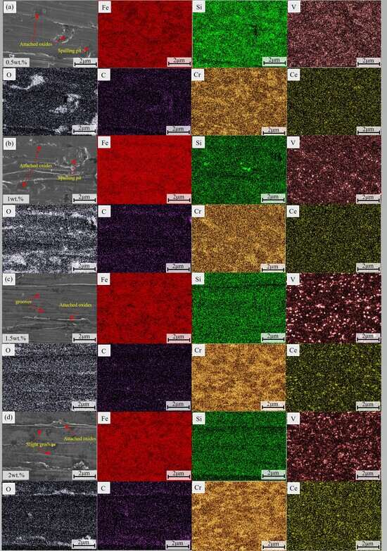
3.5.3. Corrosion Morphology

Figure 12 presents the corrosion morphologies of Cr3C2/Fe-based composite coatings with different CeO2 contents after immersion in a 3.5 wt.% NaCl solution. The dominant corrosion mode is characterized by extensive surface corrosion, accompanied by severe material spalling and deep pitting propagation. This phenomenon is primarily attributed to the preferential dissolution of the α-Fe matrix phase, which triggers the detachment of the M23C6 reinforcing phase and subsequently induces collapse-type corrosion damage. At low CeO2 contents, corrosion predominantly initiates and propagates along the highly reactive grain boundaries, leading to significant structural degradation of the coatings. With the increase in CeO2 content, the coating grains are refined and the microstructure compactness is improved. Concurrently, Ce atoms provide abundant active sites for the nucleation and growth of passivation films, facilitating the formation of a denser and more stable protective oxide layer [28], which effectively isolates the internal matrix from the corrosive electrolyte. As a result, intergranular corrosion within the coatings is significantly mitigated, with the corrosion behavior manifesting as localized small-area pitting and the overall corrosion severity being markedly reduced. When the CeO2 content reaches 2 wt.%, the grain refinement effect is most pronounced, and the passivation film formed on the coating surface is more complete and thermodynamically stable. The corroded surface only exhibits a few scattered shallow pits, which is indicative of a substantial enhancement in the corrosion resistance of the composite coating.
The elemental mapping results reveal significant loss of Fe in the corroded regions, which is consistent with the dissolution of the α-Fe phase. In addition, it can be observed that elements such as Cr and C are uniformly distributed at the grain boundaries. This is mainly attributed to the addition of CeO2, which greatly inhibits the formation of coarse carbide phases and reduces the galvanic corrosion between carbides and the matrix [29], thereby significantly enhancing the corrosion resistance of the coatings.

3.5.4. Corrosion Mechanism

During the preparation of Cr3C2/Fe-based composite coatings, a small number of intrinsic pores may form within the coating matrix, which provide preferential channels for the initiation of pitting corrosion. In the corrosion process, the Cr-rich phases distributed in the coating act as cathodes, while the α-Fe matrix serves as the anode, thus constructing a micro-galvanic cell system [30]. Therefore, when chloride ions (Cl) in the corrosive solution adsorb onto the coating surface, the α-Fe matrix undergoes preferential dissolution driven by the micro-electrochemical coupling effect.
At low CeO2 contents, the coating surface forms a passivation film primarily consisting of Cr2O3 and Fe2O3; however, this film is inherently defective with numerous pinholes and microcracks. Cl ions can easily penetrate through these structural defects to reach the underlying substrate, thereby compromising the integrity of the passivation film. Once pitting corrosion is initiated, Cl ions tend to accumulate within the corrosion pits, creating a localized acidic environment with high ion concentration. This acidic microenvironment further destabilizes the passivation film adjacent to the pits and accelerates the anodic dissolution of Cr-depleted regions. Consequently, the Cr content in the passivation film decreases continuously, which significantly impairs the barrier performance of the film and ultimately leads to extensive surface corrosion.
With the increase in CeO2 content, the formation of coarse carbide phases is effectively suppressed, which weakens the micro-electrochemical coupling effect and decelerates the preferential dissolution of the α-Fe matrix. Furthermore, Ce atoms provide abundant active nucleation sites for the formation of passivation films, promoting the rapid deposition of Cr2O3 on the surfaces of Cr-rich phases. Simultaneously, Ce4+ ions participate in the repair and regeneration of the passivation film via hydrolysis reactions, enabling the self-healing capability of the passivation layer. This multi-scale modulation effect ultimately inhibits the selective corrosion of Cr-depleted regions induced by Cl ions, thus significantly enhancing the corrosion resistance and long-term stability of the composite coatings [20]. The corrosion mechanism described above is schematically illustrated in Figure 13.

4. Conclusions

This study investigates the effects of varying CeO2 contents on the microstructure and properties of 10 wt.% Cr3C2/Fe-based composite coatings, and further elucidates the synergistic mechanism by which CeO2 and Cr3C2 co-regulate the microstructural evolution and performance of the Fe-based composite coatings. The main conclusions are summarized as follows:
(1)
The addition of CeO2 did not alter the fundamental phase composition of the coating, which remained composed of α-Fe, M23C6, and vanadium carbides. Through mechanisms such as heterogeneous nucleation and grain boundary pinning, Ce promoted the transformation of coarse dendritic grains into fine equiaxed grains. When the CeO2 content reached 2 wt.%, all grains in the coating were transformed into fine equiaxed grains.
(2)
With the increase in CeO2 content, the dendritic structure was significantly refined, and the number of grain boundaries increased, which hindered dislocation movement. Simultaneously, CeO2 facilitated the dispersion of hard carbide phases, enhancing the second-phase strengthening effect. Consequently, the microhardness and wear resistance of the coatings were substantially improved. The coating containing 2 wt.% CeO2 exhibited the highest microhardness (923.08 HV0.5, 4.56 times higher than that of the substrate), the lowest friction coefficient (0.31), and the minimum wear rate (2.0 × 10⁻³ mm3/(N·m)).
(3)
CeO2 was able to significantly enhance the corrosion resistance of the coatings. In a 3.5 wt.% NaCl solution, the 2 wt.% CeO2 coating demonstrated the optimal corrosion resistance, with a corrosion potential of −0.82 V and a corrosion current density of 2.04 × 10⁻⁶ A/cm2. This was primarily attributed to the ability of CeO2 to refine grains, inhibit the formation of coarse carbides to alleviate micro-galvanic corrosion, and promote the formation of a dense passive film with self-healing capabilities to block Cl intrusion.
Based on the aforementioned research findings, to further elevate the engineering application value and scientific research depth of this composite coating, subsequent studies should focus on the following three key aspects: First, investigating the performance enhancement effects and failure mechanisms of the coating under the coupled wear–corrosion conditions typical of coal mine shafts. Second, advancing the development of coating preparation processes tailored to the complex curved surfaces of scraper conveyor center chutes, so as to improve the practicality and stability of large-scale coating fabrication. Third, exploring synergistic modification systems incorporating multiple rare earth elements (e.g., Y2O3, La2O3); clarifying the synergistic interaction mechanisms among these rare earths, CeO2, and Cr3C2; and further optimizing the coating microstructure and overall comprehensive performance.

Author Contributions

Conceptualization, S.Y.; Methodology, S.Y.; Software, X.X.; Validation, H.L. and Z.M.; Formal analysis, H.S., X.X. and W.P.; Investigation, H.S. and X.X.; Resources, B.H.; Writing—original draft, Z.L.; Writing—review & editing, Z.L.; Supervision, B.H., H.L., Z.M. and W.P.; Project administration, B.H., H.L., Z.M. and W.P. All authors have read and agreed to the published version of the manuscript.

Funding

This research was funded by Hebei Natural Science Foundation grant number E2024209149, Tangshan Science and Technology Program grant number 24130208C, GF Key Discipline Laboratory Project grant number GFXK-202506 and Tangshan Foreign Talent Introduction Program grant number 25120201C.

Institutional Review Board Statement

Not applicable.

Informed Consent Statement

Not applicable.

Data Availability Statement

The original contributions presented in this study are included in the article. Further inquiries can be directed to the corresponding author.

Conflicts of Interest

The authors declare no conflict of interest.

References

  1. Gómez de León Hijes, F.C.; Sánchez Robles, J.; Martínez García, F.M.; García, M.A. Dynamic management of periodicity between measurements in predictive maintenance. Measurement 2023, 213, 112721. [Google Scholar] [CrossRef]
  2. Fedorko, G.; Liptai, P.; Molnár, V. Proposal of the methodology for noise sources identification and analysis of continuous transport systems using an acoustic camera. Eng. Fail. Anal. 2018, 83, 30–46. [Google Scholar] [CrossRef]
  3. Huang, S.; Li, B.; Ma, H.; Xia, R.; Wang, X.; Cui, W.; Zhang, P.; Jiao, H. Design and evaluation of abrasive wear testing device for scraper conveyor middle plates. Powder Technol. 2025, 460, 121042. [Google Scholar] [CrossRef]
  4. Ma, H.; Wang, X.; Li, B.; Liu, Z.; Bi, W.; Wei, X. Study on the mechanical effect and wear behaviour of middle trough of a scraper conveyor based on DEM MBD. Proc. Inst. Mech. Eng. Part J J. Eng. Tribol. 2022, 236, 1363–1374. [Google Scholar] [CrossRef]
  5. Chen, L.; Song, G.; Wang, D.; Zhang, X.; Hao, J. Energy consumption optimization of scraper conveyors adopting rolling friction: A technological revolution in China’s coal mining equipment. J. Ind. Saf. 2025, 2, 213–220. [Google Scholar] [CrossRef]
  6. Shi, Z.Y.; Zhu, Z.C. Study on wear behavior of middle plate during material transportation of scraper conveyor under composite working conditions. Tribol. Trans. 2017, 37, 472–478. [Google Scholar] [CrossRef]
  7. Ren, X.P. Research on application of diamond-coated wear-resistant plates in middle trough repair of scraper conveyors. Coal Chem. Ind. 2025, 48, 78–81. [Google Scholar] [CrossRef]
  8. Shi, Z.Y.; Zhu, Z.C. Case study: Wear analysis of the middle plate of a heavy-load scraper conveyor chute under a range of operating conditions. Wear 2017, 380–381, 36–41. [Google Scholar] [CrossRef]
  9. Ryba, T.; Bzinkowski, D.; Siemiątkowski, Z.; Rucki, M.; Stawarz, S.; Caban, J.; Samociuk, W. Monitoring of Rubber Belt Material Performance and Damage. Materials 2024, 17, 765. [Google Scholar] [CrossRef]
  10. Zhu, L.; Xue, P.; Lan, Q.; Meng, G.; Ren, Y.; Yang, Z.; Xu, P.; Liu, Z. Recent research and development status of laser cladding: A review. Opt. Laser Technol. 2021, 138, 106915. [Google Scholar] [CrossRef]
  11. Su, Z.; Li, J.; Shi, Y.; Ren, S.; Zhang, Z.; Wang, X. Effect of process parameters on microstructure and tribological properties of Ni60A/Cr3C2 laser cladding on 60Si2Mn steel. Surf. Coat. Technol. 2023, 473, 130005. [Google Scholar] [CrossRef]
  12. Verdi, D.; Garrido, M.A.; Múnez, C.J.; Poza, P. Cr3C2 incorporation into an Inconel 625 laser cladded coating: Effects on matrix microstructure, mechanical properties and local scratch resistance. Mater. Des. 2015, 67, 20–27. [Google Scholar] [CrossRef]
  13. Verdi, D.; Garrido, M.A.; Múnez, C.J.; Poza, P. Microscale effect of high-temperature exposition on laser cladded Inconel 625-Cr3C2 metal matrix composite. J. Alloys Compd. 2017, 695, 2696–2705. [Google Scholar] [CrossRef]
  14. Lian, G.; Gao, W.; Chen, C.; Huang, X.; Feng, M. Review on hard particle reinforced laser cladding high-entropy alloy coatings. J. Mater. Res. Technol. 2024, 33, 1366–1405. [Google Scholar] [CrossRef]
  15. Xie, Y.; Jiang, W.; Xu, K.; Wen, X.; Huang, B. Microhardness, wear resistance, and corrosion resistance of AlCoCrFeNi2.1+xCeO2 high-entropy alloy coatings by laser cladding. Mater. Today Commun. 2025, 43, 111662. [Google Scholar] [CrossRef]
  16. Wang, Y.; Kovacevic, R.; Liu, J. Mechanism of surface modification of CeO2 in laser remelted alloy spray coatings. Wear 1998, 221, 47–53. [Google Scholar] [CrossRef]
  17. Li, J.; Chen, C.; Zhang, C. Effect of nano-CeO2 on microstructure properties of TiC/TiN+nTi(CN) reinforced composite coating. Bull. Mater. Sci. 2012, 35, 399–404. [Google Scholar] [CrossRef]
  18. Chang, W.H. Study on High-Temperature Tribological Characteristics and Mechanism of Multicomponent Alloy Coatings Doped by Rare Earth Ce. Ph.D. Thesis, Henan University of Science and Technology, Luoyang, China, 2023. [Google Scholar] [CrossRef]
  19. Zhu, R.; Li, Z.; Li, X.; Sun, Q. Microstructure and properties of the low-power-laser clad coatings on magnesium alloy with different amount of rare earth addition. Appl. Surf. Sci. 2015, 353, 405–413. [Google Scholar] [CrossRef]
  20. Zhang, H.; Zou, Y.; Zou, Z.; Shi, C. Effects of CeO2 on microstructure and corrosion resistance of TiC-VC reinforced Fe-based laser cladding layers. J. Rare Earths 2014, 32, 1095–1100. [Google Scholar] [CrossRef]
  21. Han, B.; Li, M.Y.; Wang, Y. Microstructure and wear resistance of laser clad Fe-Cr3C2 composite coating on 35CrMo steel. J. Mater. Eng. Perform. 2013, 22, 3749–3754. [Google Scholar] [CrossRef]
  22. Guo, S.; Chai, C.; Hu, S.; Li, F.; Liu, Y.; Yi, J.; Yu, J.; Eckert, J. Effects of nano-CeO2 particles on the microstructural evolution and tribological performance of laser-deposited Ni45 coatings. Surf. Coat. Technol. 2025, 514, 132539. [Google Scholar] [CrossRef]
  23. Wang, Z.; Liu, H.; Huang, J.; Zhuo, S.; Wu, Y.; Wang, G.; Zheng, Z.; Qiu, Z.; Zeng, D. Improving wear and corrosion resistance of HVAF sprayed 316L stainless steel coating by adding TiB2 ceramic particles and CeO2. J. Mater. Res. Technol. 2024, 31, 1313–1325. [Google Scholar] [CrossRef]
  24. Meghwal, A.; Schulz, C.; Hall, C.; Vogli, E.; Berndt, C.C.; Ang, A.S.M. Microstructural, mechanical and high-temperature tribological performance of Fe-based fully amorphous and amorphous/crystalline coatings. Surf. Coat. Technol. 2023, 475, 130114. [Google Scholar] [CrossRef]
  25. Guo, Z.; Zhang, A.; Han, J.; Meng, J. Effect of Si Addition on Tribological Properties of NbTaWMo Refractory High-Entropy Alloy at High Temperature. Tribol. Trans. 2021, 41, 197–205. [Google Scholar] [CrossRef]
  26. Wang, Q.-Y.; Pei, R.; Liu, S.; Wang, S.-L.; Dong, L.-J.; Zhou, L.-J.; Xi, Y.-C.; Bai, S.-L. Microstructure and corrosion behavior of different clad zones in multi-track Ni-based laser-clad coating. Surf. Coat. Technol. 2020, 402, 126310. [Google Scholar] [CrossRef]
  27. Winiarski, J.; Tylus, W.; Szczygiet, B. EIS and XPS investigations on the corrosion mechanism of ternary Zn–Co–Mo alloy coatings in NaCl solution. Appl. Surf. Sci. 2016, 364, 455–466. [Google Scholar] [CrossRef]
  28. Luo, T.J.; Yang, Y.S. Corrosion properties and corrosion evolution of as-cast AZ91 alloy with rare earth yttrium. Mater. Des. 2011, 32, 5043–5048. [Google Scholar] [CrossRef]
  29. Fu, Y.; Luo, H.; Chen, X.; Prabhakar, J.M.; Wang, X.; Cheng, H.; Du, C.; Hu, S.; Li, X. The corrosion behavior and passive film properties of the cast and annealed AlCoCrFeNi2.1 eutectic high-entropy alloy in sulfuric acid solution. Corros. Sci. 2024, 240, 112456. [Google Scholar] [CrossRef]
  30. Charkhchian, J.; Zarei-Hanzaki, A.; Schwarz, T.; Lawitzki, R.; Schmitz, G.; Schell, N.; Shen, J.; Oliveira, J.; Waryoba, D.; Abedi, H. Unleashing the microstructural evolutions during hot deformation of as-cast AlCoCrFeNi2.1 eutectic high entropy alloy. Intermetallics 2024, 168, 108253. [Google Scholar] [CrossRef]
Figure 1. Powder morphology. (a,a1) Fe-based alloy powder and its magnified morphology images, (b,b1) Cr3C2 particles and its magnified morphology images, (c,c1) CeO2 powder and its magnified morphology images.
Coatings 16 00187 g001
Figure 2. Schematic diagram of laser cladding.
Coatings 16 00187 g002
Figure 3. XRD patterns of Cr3C2/Fe-based composite coatings with varying CeO2 contents.
Coatings 16 00187 g003
Figure 4. Microstructure of Cr3C2/Fe-based composite coatings with varying CeO2 contents:(a) Top region of the 0.5 wt.% CeO2 coating; (a1) Middle region of the 0.5 wt.% CeO2 coating; (a2) Bottom region of the 0.5 wt.% CeO2 coating; (b) Top region of the 1 wt.% CeO2 coating; (b1) Middle region of the 1 wt.% CeO2 coating; (b2) Bottom region of the 1 wt.% CeO2 coating; (c) Top region of the 1.5 wt.% CeO2 coating; (c1) Middle region of the 1.5 wt.% CeO2 coating; (c2) Bottom region of the 1.5 wt.% CeO2 coating; (d) Top region of the 2 wt.% CeO2 coating; (d1) Middle region of the 2 wt.% CeO2 coating; (d2) Bottom region of the 2 wt.% CeO2 coating.
Coatings 16 00187 g004
Figure 5. EDS elemental surface scan distribution map of Cr3C2/Fe-based composite coatings with varying CeO2 contents. (a) EDS mapping images of the 0.5 wt.% CeO2 coating; (b) EDS mapping images of the 1 wt.% CeO2 coating; (c) EDS mapping images of the 1.5 wt.% CeO2 coating; (d) EDS mapping images of the 2 wt.% CeO2 coating.
Coatings 16 00187 g005
Figure 6. Microhardness distribution of the coatings (a) Microhardness distribution curve; (b) Average microhardness diagram.
Coatings 16 00187 g006
Figure 7. (a) Friction coefficient curve, (b) Average friction coefficient, (c) Average wear rate, (d) Cross-sectional profile.
Coatings 16 00187 g007
Figure 8. Worn surface morphologies and EDS elemental mapping of coatings with different CeO2 contents (a) EDS mapping images of the wear morphology of the 0.5 wt.% CeO2 coating; (b) EDS mapping images of the wear morphology of the 1 wt.% CeO2 coating; (c) EDS mapping images of the wear morphology of the 1.5 wt.% CeO2 coating; (d) EDS mapping images of the wear morphology of the 2 wt.% CeO2 coating.
Coatings 16 00187 g008
Figure 9. Schematic Illustration of the Wear Mechanism.
Coatings 16 00187 g009
Figure 10. Potentiodynamic polarization curves.
Coatings 16 00187 g010
Figure 11. (a) Bode impedance–frequency plot, (b) Bode phase–frequency plot, (c) Nyquist plot, (d) Equivalent circuit diagram.
Coatings 16 00187 g011
Figure 12. Corrosion morphologies and EDS elemental mapping results of coatings with different CeO2 contents. (a) EDS mapping images of the corrosion morphology of the 0.5 wt.% CeO2 coating; (b) EDS mapping images of the corrosion morphology of the 1 wt.% CeO2 coating; (c) EDS mapping images of the corrosion morphology of the 1.5 wt.% CeO2 coating; (d) EDS mapping images of the corrosion morphology of the 2 wt.% CeO2 coating.
Coatings 16 00187 g012
Figure 13. Corrosion mechanism.
Coatings 16 00187 g013
Table 1. Composition of Q345 steel (wt.%).
ElementCSiPSMnVTiFe
wt.%0.180.400.0250.0251.500.100.05Balance
Table 2. Fe-based alloy powder composition (wt.%).
ElementFeCCrVSi
wt.%Balance24.56.81.2
Table 3. Fitted Potentiodynamic polarization curve data.
SampleEcorr/VIcorr/A·cm−2
substrate−1.351.03 × 10−5
0.5 wt.%−1.005.49 × 10−6
1 wt.%−0.984.54 × 10−6
1.5 wt.%−0.844.33 × 10−6
2 wt.%−0.822.04 × 10−6
Disclaimer/Publisher’s Note: The statements, opinions and data contained in all publications are solely those of the individual author(s) and contributor(s) and not of MDPI and/or the editor(s). MDPI and/or the editor(s) disclaim responsibility for any injury to people or property resulting from any ideas, methods, instructions or products referred to in the content.

