Article

Research on the Effect of Argon–Nitrogen Ratio on the Mechanical Properties and Corrosion Behavior of CrN-Ag Self-Lubricating Coatings

1
Special Equipment Safety Supervision Inspection Institute of Jiangsu Province, Nanjing 210036, China
2
School of Power & Mechanical Engineering, Wuhan University, Wuhan 430072, China
*
Authors to whom correspondence should be addressed.
Coatings 2025, 15(9), 1107; https://doi.org/10.3390/coatings15091107
Submission received: 30 July 2025 / Revised: 7 September 2025 / Accepted: 16 September 2025 / Published: 20 September 2025
(This article belongs to the Section Surface Characterization, Deposition and Modification)

Abstract

Self-lubricating coatings are an effective solution for achieving stable and reliable lubrication in mechanical equipment; however, most self-lubricating coatings currently available still have certain shortcomings in terms of lubricity. In this paper, by regulating the argon and nitrogen flow ratio, a CrN-Ag composite self-lubricating coating with excellent lubrication performance was prepared, with a minimum wear rate and friction coefficient of only 2.3 mm3·10−5/N·m and 0.15, respectively, and a stable performance during long-term service. Furthermore, through systematic characterization of the coating composition, structure, and performance, the laws of the coating’s evolution were revealed based on the argon–nitrogen ratio. The results confirmed that the argon-to-nitrogen ratio had no significant effect on the coating composition and structure, while the addition of Ag dominated the high-temperature oxidation process of the coating and improved its tribological properties. In addition, while increasing the nitrogen flow ratio to a certain extent is beneficial for preparing coatings with high bonding strength and low wear rates and friction coefficients, at the same time, an excessively high nitrogen flow ratio can reduce the density of the coating, increase its hydrophilicity, and deteriorate its corrosion resistance.

1. Introduction

Friction and wear failure seriously threaten the long-term, stable service of mechanical equipment and cause approximately 23% of global energy consumption to be wasted each year [1,2]. The use of appropriate lubrication technology is an effective solution to unacceptable friction between mechanical equipment components. Transition metal nitride CrN coatings [3,4] have long been the preferred lubricating coatings due to their excellent mechanical properties. Furthermore, the good thermal stability of the coatings has led to their application in high-temperature fields as a replacement for liquid lubricants that decompose easily at high temperatures. However, CrN coatings show a high coefficient of friction [5,6] (approximately 0.7), which has an adverse effect on their long-term service life.
Applying composite coating technology to combine CrN, which has good load-bearing capacity, with materials that have low friction coefficients to prepare self-lubricating coatings can effectively solve the above-mentioned difficulties [6]. Self-lubricating coatings generally consist of a substrate phase and a lubricating phase, in which the harder CrN serves as the substrate to support the load, while the low-friction coating with low shear strength acts as the lubricating phase to provide good lubrication. CrN exhibits not only high hardness and wear resistance, but also excellent high-temperature stability, which makes it one of the best choices for substrate materials. The lubricating phase materials currently in service mainly include materials with layered structures (graphite [7], MoS2 [8]), soft metals (Ag [9,10], Au, Pt), a number of types of metal oxides (PbO [11], TiO [12]), and inorganic fluorides (CaF2 [13,14], BaF2 [14]), etc. The soft metal Ag presents the characteristics of good ductility, low shear strength, and good thermal conductivity [15,16], and its dynamic hardness is higher than its static hardness [17]. In addition, Ag has good antioxidant properties and economic advantages, which together make Ag a competitive alternative lubricant material. Combining it with CrN could achieve good tribological effects. During the friction process, the Ag composite in the CrN matrix diffuses to form a lubricating film at the friction interface, which thus achieves long-term good friction. For a CrN-Ag composite self-lubricating coating, the coating’s preparation process significantly affects the consumption rate of Ag and the structure of CrN, which is closely related to the long-term tribological performance of the coating. A thorough understanding of the lubrication and failure mechanisms of the coating as well as exploration of the optimal coating preparation process are crucial for the development of high-performance CrN-Ag composite self-lubricating coatings. A large number of studies have reported on the effects of substrate temperature, Ag content, and other factors on the self-lubricating properties of CrN-Ag coatings, in which most of the CrN-Ag coatings were prepared in a pure nitrogen atmosphere, and few studies have systematically discussed the effects of the argon–nitrogen ratio on the mechanical properties and corrosion resistance of the coatings. Therefore, an in-depth analysis of the comprehensive effects of the argon–nitrogen ratio on the coatings is both necessary and novel.
Magnetron sputtering technology uses ionized argon ions to bombard the target material, sputtering atoms to form a film. Preparation of coatings using this technology often results in strong bonding, few defects, and precise control of coating thickness, which has led to its widespread application in the field of high-quality thin film preparation. In this paper, CrN-Ag composite self-lubricating coatings were prepared by regulating the argon–nitrogen ratio at different argon and nitrogen flow ratios using magnetron sputtering technology. The composition, structure, and various properties of the coatings at different argon–nitrogen ratios were analyzed in depth, revealing the mechanism of the argon–nitrogen ratio’s influence and obtaining a set of optimized preparation process parameters. The results obtained can provide scientific reference for the commercial application of CrN-Ag composite coatings and the development of new self-lubricating coatings.

2. Experimental Section

2.1. Preparation of CrN-Ag Coating

The detailed preparation method for the CrN-Ag composite self-lubricating coating is as follows: A 150 mm-diameter AgCr target (Ag70 at.%, Cr30 at.%) is used to deposit the CrN-Ag composite coating on two substrates, silicon wafers and 304 stainless steel, that have been pre-cleaned and ion-etched, in which the coating deposited on the silicon wafer is used for morphology and composition testing, while the coating deposited on 304 stainless steel is used for mechanical properties and corrosion resistance testing. The deposition system used is the magnetron sputtering system Nano-100 (LeBei, Shenyang, China). The parameter combination of target–substrate distance 70 mm, temperature 150 °C, gas pressure 1 Pa, and sputtering power 700 W were chosen to deposit the coating, with a sputtering duration of 30 min. Different CrN-Ag coatings were achieved by regulating the argon–nitrogen ratio. For convenience, the different coatings were numbered separately, with specific details shown in Table 1.

2.2. Measurement Apparatus and Characterization Methods

(1)
Chemical composition and morphology
A scanning electron microscope (SEM, MIRA3 LMH, TESCAN, Brno, Czech Republic) was used to observe the cross-section and surface morphology of the coating, and an energy dispersive spectrometer (EDS, Aztec Energy X-Max 20, United Kingdom of Great Britain and Northern Ireland, Oxford, UK) connected to the SEM was used to detect the elemental composition and distribution of the coating.
(2)
Structure
An X-ray diffractometer (XRD, Tongda TDM-10, Tongda, Dandong, China) equipped with a Cu Kα radiation source and a wavelength of 1.54 Å was used to analyze the crystal structure of the coating. The test parameters selected were a scanning range of 20–80°and a scanning speed of 2°/min.
(3)
Mechanical properties
The coating hardness was tested using a nanoindenter (G200, KLA, Milpitas, CA, USA), with the continuous stiffness method at a load of 25 mN. During the whole test process, the maximum indentation depth did not exceed 10% of the coating thickness to avoid the influence of substrate effects. The ball-on-disk friction and wear tester (MST1000, Huahui, Guangzhou, China) was used to test the tribological properties of the coating, with a test load of 50 g, a rotational speed of 200 r/min, and a test duration of 5 min. After the test, a 3D profilometer (NewView 900, ZYGO, Middlefield, CT, USA) was used to observe the cross-section of the coating’s abrasion marks, and the coating’s wear rate was calculated using Equation (1):
W R = V F × L
where WR is the wear rate, V is the wear volume, F is the load, and L is the sliding distance.
Hertz contact stress was applied to evaluate the reasonableness of friction parameter selection. The calculation of Hertz contact stress is shown in Equations (2)–(4):
σ m a x = 3 F 2 π a 2
a = ( 3 F R 4 E * ) 1 3
1 E * = 1 υ 1 2 E 1 + 1 υ 2 2 E 2
In this experiment, F represents the normal load, which is 0.49 N; E and υ are the elastic modulus and Poisson’s ratio of the counter-abrasive material, respectively; R denotes the radius of the grinding ball. The counterball selected was a 3 mm diameter 304 stainless steel ball with R, E, and υ values of 1.5 mm, 193 GPa, and 0.29, respectively. For the CrN-Ag composite coating material, the elastic modulus was measured using a nanoindenter and found to be approximately 111.8 GPa, and no publicly available data on its Poisson’s ratio and yield strength exists. Therefore, we employed the commonly used empirical Equations (5) and (6) for estimation:
ν c o m p o s i t e = V C r N · υ C r N + V A g · υ A g
σ c o m p o s i t e = V C r N · σ C r N + V A g · σ A g
where υ A g = 0.31, σ A g = 150 MPa, VAg = 27.4%, υ C r N = 0.25, σ C r N = 3 GPa, and VCrN = 72.6%.
The final calculation yields σ m a x = 3.33 MPa < 0.8 σ y i e l d c o m p o s i t e = 1.78 GPa, thus confirming the selection of the friction parameter is reasonable.
The multifunctional material surface performance tester (Huahui, MFT-4000) served to perform scratch tests on the coating, with a scratch length of 6 mm and a maximum load of 60 N.
(4)
High-temperature stability
High-temperature stability tests were conducted in a muffle furnace at heating and cooling rates of 5 °C/min. The test temperatures were set at 500 °C, 650 °C, and 750 °C, with a holding time of 2 h.
(5)
Electrochemical Corrosion
The water contact angle has a significant impact on the corrosion resistance of the coating. Prior to conducting electrochemical corrosion testing, the coating was subjected to water contact angle testing using a self-built water contact angle measuring instrument with a droplet volume of 3 μL. The corrosion resistance performance of the coating was tested in a 3.5 wt.% NaCl solution. The test employed a three-electrode system with a platinum plate as the counter electrode, Ag/AgCl as the reference electrode, and the coating sample as the working electrode. During testing, the dynamic potential polarization mode was used to scan the potential at a fixed rate of 10 mV/s with a scanning range of −0.5 V to 0 V, which are referenced to the reference electrode.
All tests were repeated five times to minimize errors.

3. Results and Discussion

3.1. Morphology, Structure, and Chemical Composition of CrN-Ag Coating

The surface and cross-sectional morphology of the CrN-Ag coating are shown in Figure 1. The surfaces of the CrN-Ag#1 coating (Figure 1a) and the CrN-Ag#6 coating (Figure 1f) are completely covered by micron-sized particles, resulting in higher roughness compared to other coatings. Additionally, the particles on the surface of the CrN-Ag#6 coating are more loosely bound, which may be attributed to a reduced atomic kinetic energy caused by an excessively high nitrogen gas flow ratio during the sputtering process, leading to a decrease in coating density [18]. Generally, with nitrogen, the sputtering ability is lower than that of argon, so in a low argon-to-nitrogen ratio where there is more nitrogen than argon, a loose surface structure appears (Figure 1f). Ag typically exists in the form of Ag nanoclusters in CrN-Ag coatings [19,20], and uniformly distributed Ag nanoparticles can be clearly observed in the CrN-Ag#3, CrN-Ag#4, and CrN-Ag#5 coatings (yellow arrows in Figure 1c–e). The incorporation of Ag disrupts the columnar growth of CrN [21]. The cross-section of the CrN-Ag coating shows no obvious columnar structure, exhibiting good density and no obvious cracks. In addition, the thickness of the CrN-Ag coating shows a significant decrease trend as the nitrogen flow ratio increases, which is the result of the combined effects of reduced sputtering efficiency due to increased nitrogen content [19] and target poisoning [22].
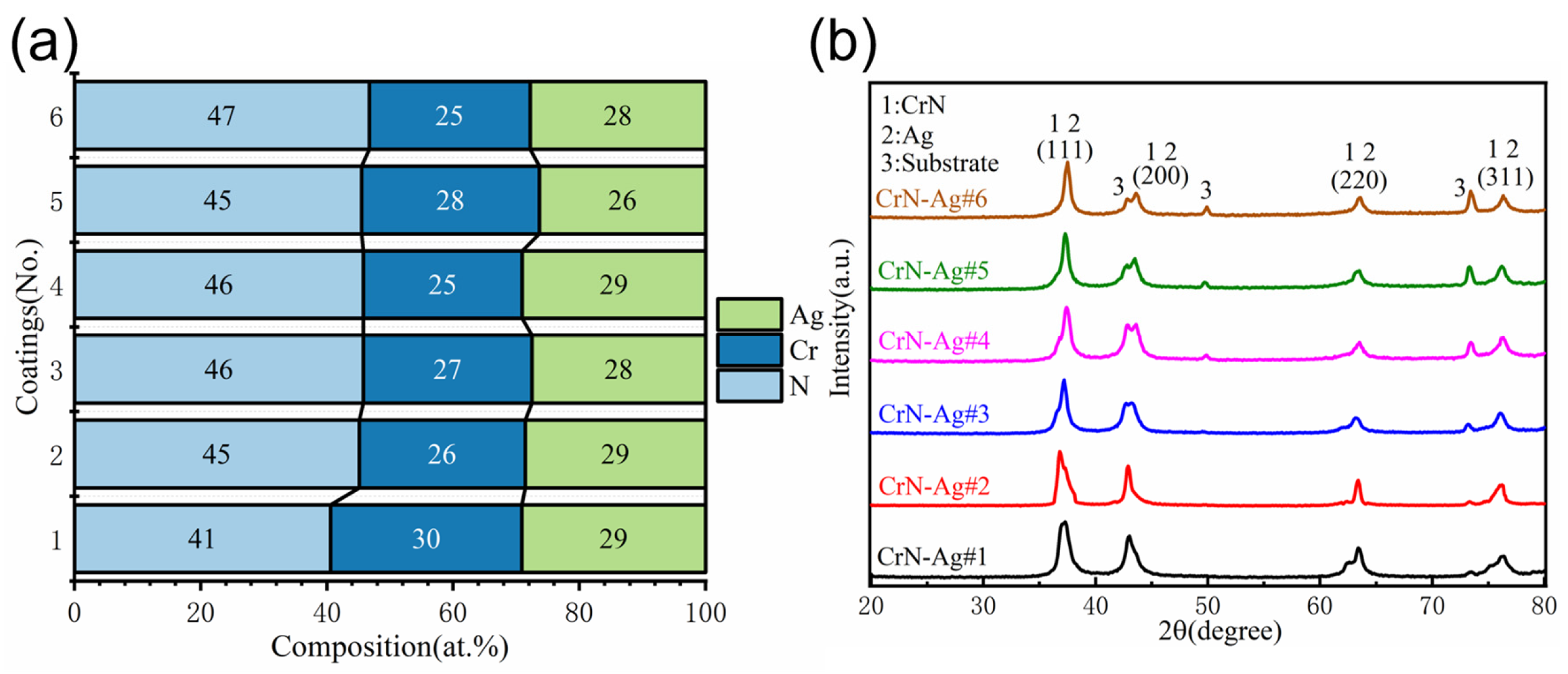
Figure 2 presents the composition of the CrN-Ag coating and its XRD pattern. The Cr:N ratio in the CrN-Ag coating is significantly higher than the ideal 1:1 ratio (Figure 2a), mainly caused by two factors. On one hand, under low-temperature sputtering conditions, metastable CrNX (X > 1) is formed, which incorporates into the CrN crystal lattice, leading to an overall higher Cr:N ratio in the coating [23]. On the other hand, in a sputtering atmosphere containing nitrogen, nitrogen-terminated surfaces can result in an excess of N on the coating surface [24]. Since EDS is a typical surface-testing technique, the measured N content in the results tends to be elevated. The CrN-Ag coating exhibits a mixed grain orientation (Figure 2b) [3,5] with a typical FCC structure, and the (111) peak and (200) peak of CrN (PDF#11-0065) and Ag (PDF#04-0783) can be observed at approximately 36.8° and 42.9°, respectively. Additionally, as the nitrogen flow ratio increases, the diffraction peaks of the CrN-Ag coatings gradually shift toward larger angles. Compared to standard CrN, the (111) and (200) peaks of the CrN-Ag#1 coating shift approximately 0.8° toward smaller angles, while the CrN-Ag#6 coating shows almost no shift. This can be attributed to the decrease in sputtering efficiency caused by the increase in nitrogen content [19], leading to a reduction in residual compressive stress in the coating and resulting in the rightward shift of the diffraction peaks [25].

3.2. High-Temperature Stability of CrN-Ag Coating

Figure 3a–f demonstrate the surface morphology of the CrN-Ag coating after annealing in air at 500 °C, 650 °C, and 750 °C for 2 h. After annealing at 500 °C, the surfaces of CrN-Ag coatings exhibited bright, spherical Ag particles formed by diffusion [5,26,27], but the Ag particles in the CrN-Ag#1 to CrN-Ag#5 coatings were larger in size and number compared to those in the CrN-Ag#6 coating. The darker regions in the coatings were mainly composed of CrN and its oxides, which have lower atomic mass and secondary electron yield [25], a feature that can be more clearly observed in the EDS mapping (Figure 4c). As the annealing temperature was further increased to 750 °C, the CrN-Ag coating exhibited a completely different surface morphology. The surfaces of the CrN-Ag#1 to CrN-Ag#3 coatings were almost entirely covered by further-diffused and enlarged spherical Ag particles [6], whereas the surfaces of the CrN-Ag#4 to CrN-Ag#6 coatings were filled with “flake-like” and “block-like” structures, which is primarily due to the different oxidation behaviors of the coatings caused by different Ag content. The CrN layer oxidizes at temperatures between 400 and 600 °C to produce Cr2O3 [28,29], whereas, at 650 °C, Cr2O3 further reacts with Ag to produce Ag2CrO4 [30]. As shown in Figure 4b, the CrN-Ag#6 coating mainly contained three elements after being kept at 750 °C for 2 h with the Cr:O ratio close to 1:4, and N was not detected, which could be caused by the detection depth of EDS or the complete oxidation of CrN. In addition, the XRD pattern (Figure 4d) clearly presents the diffraction peaks of Ag2CrO4 (PDF#26-0952) and AgCrO2 (PDF#32-1001), as well as the diffraction peak of Ag. Considering that AgCrO2 is produced by the reaction of Ag2CrO4 and Cr2O3 [30] at temperatures exceeding 650 °C, it can be inferred that the “flake-like, block-like” structure on the surface of the CrN-Ag#4 to CrN-Ag#6 coatings is mainly composed of Ag2CrO4, a small amount of AgCrO2 and unreacted Ag. For CrN-Ag coatings prepared in different argon–nitrogen ratio atmospheres, the Ag content in each coating is very similar (Figure 2a). Coatings prepared in a higher argon–nitrogen ratio atmosphere, such as the CrN-Ag#1 coating, which is thicker, contain a higher total amount of Ag, which allows Ag particles to eventually diffuse and cover the entire surface during annealing, thereby preventing CrN from coming into contact with oxygen in the air. This inhibits the formation of Cr2O3 and ultimately prevents the formation of “flake-like” Ag2CrO4 and AgCrO2. As shown in Figure 3a and Figure 4a, the process of Ag gradually diffusing to the surface and inhibiting oxidation can be clearly observed, which causes the Ag content to increase from 43% to 86%, while the oxygen content gradually decreases. In contrast, for thinner coatings prepared in a lower argon–nitrogen ratio atmosphere, Ag particles are difficult to spread and grow to cover the entire surface, and Ag diffusion to the surface creates micro-pores that serve as channels for oxygen to react with CrN [29], which cannot effectively prevent CrN oxidation. On the contrary, the presence of oxygen channels accelerates the oxidation process, resulting in noticeable oxidation of the coating at lower temperatures (Figure 3d–f). Thus, it is not difficult to see that the Ag content in the coating dominates the oxidation behavior of the coating. The diffusion and aggregation of Ag have a positive effect on the oxidation resistance of the coating. A higher Ag content means better oxidation resistance, enabling it to maintain a certain degree of stability at temperatures as high as 750 °C.

3.3. Mechanical Properties of CrN-Ag Coating

Figure 5b illustrates the trend of CrN-Ag coating hardness and elastic modulus with changes in nitrogen flow ratio. Compared with pure CrN coatings, the addition of soft metal Ag has an adverse effect on the coating, making it difficult to restrict dislocation movement under load and thereby reducing coating hardness [31]. With the increase in the argon-to-nitrogen ratio, the coating hardness and elastic modulus first increase and then decrease. It reached a peak hardness of 7.9 GPa for the CrN-Ag#2 coating, after which it gradually decreased. The lower hardness of the CrN-Ag#1 coating can be attributed to its reduced nitrogen content (Figure 2a), indicating fewer Me-N bonds compared to other coatings. Further increasing the nitrogen gas flow rate resulted in a decrease in coating hardness, which could be attributed to both reduced sputtering efficiency at high nitrogen flow rates, leading to lower coating density (Figure 1f), and the release of residual stresses within the coating (Figure 2b). The CrN-Ag#5 coating exhibited the lowest hardness value at 2.2 GPa. In fact, the hardness of coating systems is influenced by many different factors, including composition, structure (grain size, growth direction), residual stress [22,32], and density [33]. These factors interact to determine the hardness of the coating, which is why the hardness of CrN-Ag coatings does not show a clear trend with changes in nitrogen flow ratio.
The average coefficient of friction of the CrN-Ag coating and the variation of the coefficient of friction over time during the friction process are shown in Figure 5a,c. The friction coefficient of pure CrN coatings is approximately 0.7 [5,6]. After the addition of Ag as a lubricating phase, the friction performance of CrN-Ag coatings significantly improves, with the lowest friction coefficient being 0.15 (CrN-Ag#5 coating) and the highest being 0.59 (CrN-Ag#6 coating). Furthermore, the friction coefficient of the CrN-Ag#5 coating remains highly stable throughout the entire friction process, showing virtually no change (Figure 5c), indicating its excellent friction performance. The higher average friction coefficients of the CrN-Ag#1 and CrN-Ag#6 coatings are related to their surfaces having more particles (Figure 1) and higher surface roughness. In contrast, the CrN-Ag#2 to CrN-Ag#5 coatings, which have smoother surfaces, exhibit lower friction coefficients.
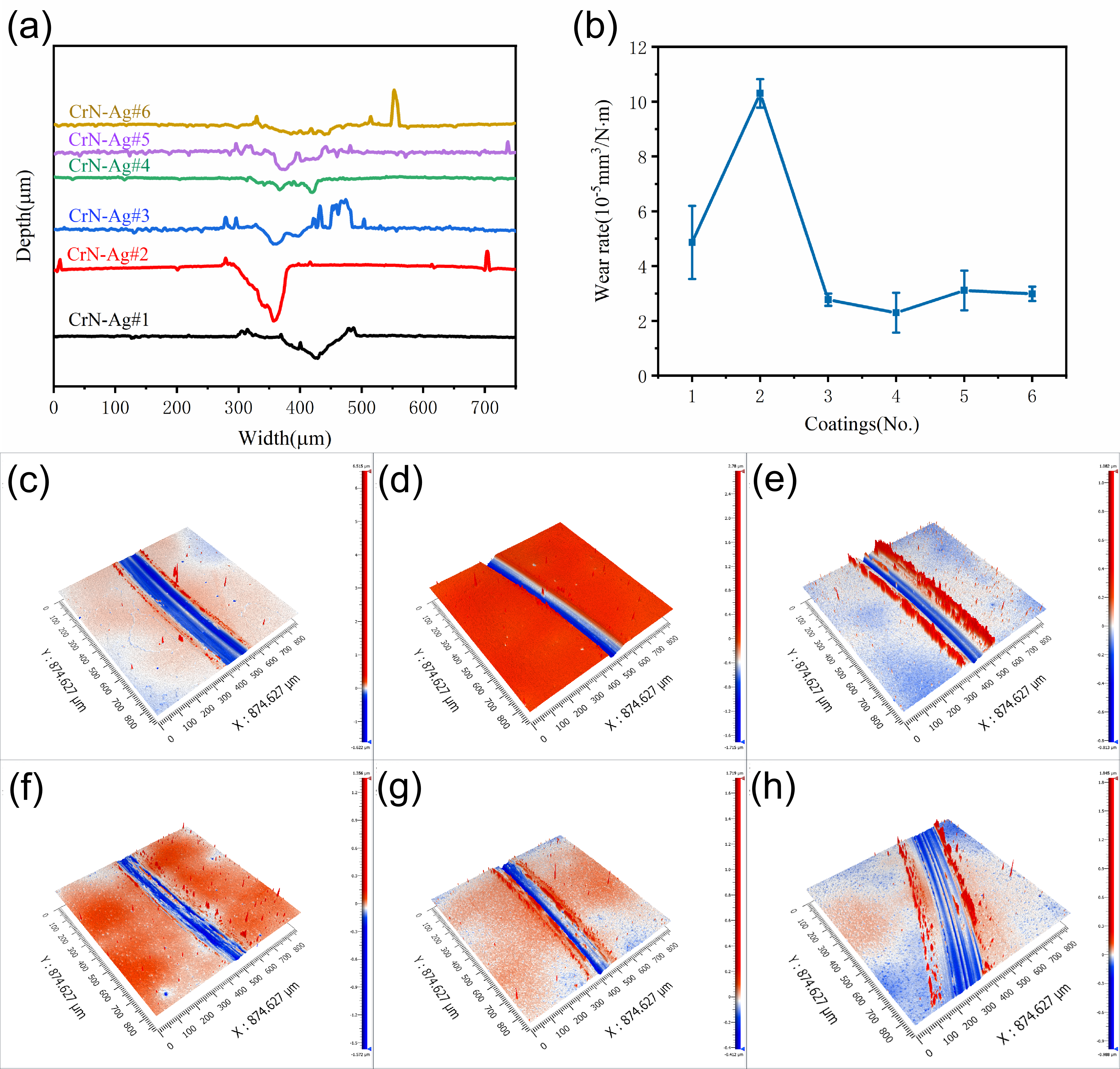
Figure 6 shows the 3D morphology of the CrN-Ag coating’s wear marks, the cross-sectional profile of the wear marks, and the wear rate. An increase in the nitrogen flow ratio causes the wear rate of the coating to gradually decrease. The CrN-Ag#3 to CrN-Ag#6 coatings prepared at higher nitrogen flow ratios all exhibit low and similar wear rates (Figure 6b). The CrN-Ag#2 coating exhibits the most severe wear (Figure 6a) and thus the poorest wear resistance, with a wear rate of 10.3 mm3·10−5/N·m, approximately 4.5 times that of the most wear-resistant CrN-Ag#4 coating (wear rate of 2.3 mm3·10−5/N·m). From the three-dimensional contour morphology of the wear marks on the CrN-Ag coatings, wear products accumulated on both sides of the trajectory can be observed. Their height exceeds that of the undamaged coating surface, which makes the coating surface have obvious protrusions (Figure 6c–f). This is caused by the broken oxide film being continuously “swept” out of the wear marks under the action of the wear ball during the friction process. Additionally, distinct plow grooves are clearly visible within the wear track. The formation of plow grooves is closely related to the fragmentation of the oxide film, which will be discussed in detail in the following sections.
To further study the friction and wear behavior of CrN-Ag coatings, SEM was used to observe the wear tracks of the coatings, with the results shown in Figure 7. Formation of an Ag lubricating film during friction is the main reason why the friction coefficient of CrN-Ag coatings is lower than that of CrN coatings. In Figure 7ai,fi, the lubricating film (yellow arrow) can be clearly observed in the wear marks. Generally, coatings typically suffer the following processes during friction and wear. First, the lubricating film gradually oxidizes during friction to form a brittle oxide film, and then, under the tensile stress generated during friction, cracks form and propagate in the oxide film [34]. When the cracks propagate to a certain extent, the oxide film breaks, peels off, and causes irregular fracture marks. At this stage, the primary wear mechanism is oxidative wear. The detached oxide film then acts as a third body in the friction process, continuously cutting and scratching the coating [35,36] and creating “plow grooves” on the coating surface, transforming the coating’s wear mechanism into abrasive wear. Abrasive wear exposes the unoxidized coating, then repeats the process of oxidation, fragmentation, and abrasive wear. Within the morphology of the CrN-Ag#6 coating, obvious oxide film (Figure 7f), cracks, and irregular fractures caused by the peeling of the oxide film can be observed, and the oxygen content in the oxide film is approximately 48 at.% (Figure 5d). In contrast, there were no obvious oxide films observed on the surfaces of the other coatings (Figure 7a–f). Instead, obvious “plow grooves” parallel to the friction direction were observed, and EDS results confirmed that the oxygen content in the wear marks was lower than that of the CrN-Ag#6 coating (Figure 5d), suggesting that the primary wear mechanism had shifted from oxidative wear to abrasive wear.
The bond strength between the coating and the substrate serves as one of the important performance indicators of the coating. The test results for the bond strength of the coating are presented in Figure 8. In the process of the scratch test, the load is uniformly increased from 0N to the maximum load of 60N, causing the coating to gradually fail and peel off, and the entire failure process can be divided into three stages, each corresponding to three critical loads: LC1, LC2, and LC3. LC1 corresponds to the load at which the coating begins to crack; at LC2, the coating begins to peel off; and at LC3, the coating completely peels off, typically used to characterize the coating’s adhesion strength [37]. The determination of LC2 is shown in Figure 8a. For soft-substrate, hard-coating systems, the friction coefficient curve and friction force curve are mainly used to determine LC2, with the acoustical signal curve used as an auxiliary judgment [37]. As the load reaches approximately 7.5 N, a distinct acoustical signal is observed, while both the friction force and friction coefficient show no significant changes (Figure 8a), indicating the presence of localized cracking within the coating; therefore, LC1 = 7.5 N. The load continues to increase to approximately 28 N, both the friction coefficient and friction force exhibit a significant change, accompanied by a substantial increase in acoustic signal amplitude. At this point, the coating cracks further and begins to peel off, so the sample’s bond strength can be characterized as LC2 = 28 N. When the load is approximately 47N, the coefficient of friction and friction force undergo another transition accompanied by a distinct acoustic signal, at which point the coating is completely peeled off, corresponding to load LC3. The adhesion strength LC2 of the CrN-Ag coating was measured using the same method as described above, as shown in Figure 8b. A higher nitrogen gas flow rate ratio has a positive effect on enhancing the adhesion strength of the coating. The CrN-Ag#3, CrN-Ag#4, and CrN-Ag#5 coatings prepared under a higher nitrogen gas flow rate ratio all exhibit higher adhesion strengths, with the optimal adhesion strength achieved in the CrN-Ag#5 coating, where LC2 = 74.6 N.

3.4. Corrosion Resistance of CrN-Ag Coating

Water contact angle is usually thought to have a significant correspondence with the corrosion resistance of coatings in the superhydrophobic field. Before the corrosion resistance of coatings was tested, the water contact angle of the coatings was measured (Figure 9a). CrN-Ag coatings exhibit significant hydrophilicity. Coatings prepared under different argon–nitrogen ratios all present a water contact angles of less than 90°, and as the nitrogen flow ratio increases, the water contact angle of the coating gradually decreases, indicating increased hydrophilicity. The CrN-Ag#6 coating has the strongest hydrophilicity, with a water contact angle of 27.5°. Its strong hydrophilicity may be related to its rough and uneven surface, which has a large number of pits, causing the wetting mode to change from Cassie–Baxter to Wenzel mode [38]. The water contact angle of the coating did not show a significant correlation with the corrosion current density of the coating (Figure 9c). It can thus be considered that for CrN-Ag coatings, the water contact angle is not the main factor affecting the corrosion resistance of the coating. The polarization curves of the CrN-Ag coatings are shown in Figure 9b, and the corrosion current and corrosion potential of the coating were calculated using the Tafel curve extrapolation method [39,40], with the results shown in Figure 9c. The corrosion potential and corrosion current density of the CrN-Ag coating exhibit identical trends with changes in the argon-to-nitrogen ratio. Corrosion current density is a decisive parameter for evaluating corrosion resistance, with higher corrosion current density indicating a more pronounced thermodynamic corrosion tendency [41]. The CrN-Ag#2 coating had the highest corrosion current density, while the CrN-Ag#5 coating had the lowest, with values of 7.0 μA/cm2 and 0.13 μA/cm2, respectively, indicating the worst and best corrosion resistance.

4. Conclusions

In this paper, CrN-Ag composite self-lubricating coatings were designed and prepared by controlling the argon–nitrogen ratio in the sputtering atmosphere during the preparation process. The structure, composition, and various properties of the CrN-Ag composite coatings were systematically studied to analyze the evolution of the coating properties and obtain a set of optimized preparation process parameters.
The composition of the coatings prepared under different argon–nitrogen ratios showed no significant changes, and all exhibited a single FCC structure with mixed grain orientations. The Ag content dominated the high-temperature oxidation process of the CrN-Ag coatings. For thicker coatings containing more Ag, Ag diffused to the surface at high temperatures and prevented the oxidation of the CrN substrate, thereby giving the coatings good oxidation resistance. In contrast, thinner coatings do not have sufficient Ag protection to prevent oxidation, and will rapidly oxidize at high temperatures to produce Ag2CrO4 and AgCrO2. The incorporation of Ag has an adverse effect on the hardness of CrN-Ag coatings, but it significantly improves the lubricity of the coatings. Compared with pure CrN coatings, the friction coefficient of CrN-Ag coatings can be as low as 0.15, and it does not change significantly during long-term friction, demonstrating excellent tribological performance. In the early stages of friction, the abrasion mechanism of the coating is mainly oxidative wear, which gradually transforms into abrasive wear as friction progresses. In addition, increasing the nitrogen flow ratio is conducive to the preparation of more wear-resistant coatings with higher bonding strength, but at the same time, it reduces the density of the coating and increases its hydrophilicity. Further reducing the argon–nitrogen ratio to 1:5 would also have adverse effect on the corrosion resistance of the coating.

Author Contributions

Conceptualization, X.M., Z.F. and Z.Z.; Methodology, Y.Z., H.H., Z.Z. and B.Y.; Software, H.H., L.C. and Z.Z.; Validation, H.H., Z.F., Z.Z. and B.Y.; Formal analysis, H.H., X.M., L.C. and B.Y.; Investigation, Z.F., Z.Z. and B.Y.; Resources, H.H. and L.C.; Data curation, Z.F. and Z.Z.; Writing—original draft, Z.Z.; Writing—review & editing, Y.Z. and Z.Z.; Visualization, Z.F. and B.Y.; Supervision, Y.Z., X.M., L.C. and B.Y.; Project administration, Y.Z., X.M. and B.Y.; Funding acquisition, Y.Z., X.M. and B.Y. All authors have read and agreed to the published version of the manuscript.

Funding

This work is supported by National Market Supervision and Administration Bureau Science and Technology Plan Project: “Research on Sensing and Detection Technology for Stress Conditions of High-Temperature Bolts in Special Equipment” (2024MK039).

Data Availability Statement

The original contributions presented in this study are included in the article. Further inquiries can be directed to the corresponding authors.

Conflicts of Interest

The authors declare no conflict of interest.

References

  1. Zhang, X.; Zeng, Z.; Zeng, X.; Pelenovich, V.; Wan, Q.; Pogrebnjak, A.; Xue, L.; Chen, Y.; Yang, B. Hardening mechanism and plastic deformation behavior in super-hard AlCrNbSiTiN high-entropy nitride nanocomposite coatings. Mater. Res. Lett. 2024, 13, 103–112. [Google Scholar] [CrossRef]
  2. Holmberg, K.; Erdemir, A. Influence of tribology on global energy consumption, costs and emissions. Friction 2017, 5, 263–284. [Google Scholar] [CrossRef]
  3. Mulligan, C.P.; Gall, D. CrN–Ag self-lubricating hard coatings. Surf. Coat. Technol. 2005, 200, 1495–1500. [Google Scholar] [CrossRef]
  4. Barshilia, H.C.; Prakash, M.S.; Jain, A.; Rajam, K.S. Structure, hardness and thermal stability of TiAlN and nanolayered TiAlN/CrN multilayer films. Vacuum 2005, 77, 169–179. [Google Scholar] [CrossRef]
  5. Mulligan, C.P.; Blanchet, T.A.; Gall, D. CrN–Ag nanocomposite coatings: Tribology at room temperature and during a temperature ramp. Surf. Coat. Technol. 2010, 204, 1388–1394. [Google Scholar] [CrossRef]
  6. Incerti, L.; Rota, A.; Valeri, S.; Miguel, A.; García, J.A.; Rodríguez, R.J.; Osés, J. Nanostructured self-lubricating CrN-Ag films deposited by PVD arc discharge and magnetron sputtering. Vacuum 2011, 85, 1108–1113. [Google Scholar] [CrossRef]
  7. Zhang, S.; Gong, X.; Yu, R.; Xing, Q.; Xu, L.; Wang, Z. Self-lubrication and wear-resistance mechanism of graphene-modified coatings. Ceram. Int. 2020, 46, 15915–15924. [Google Scholar]
  8. Lv, X.; Zou, G.; Ling, K.; Yang, W.; Mo, Q.; Li, W. Tribological properties of MAO/MoS2 self-lubricating composite coating by microarc oxidation and hydrothermal reaction. Surf. Coat. Technol. 2021, 406, 126630. [Google Scholar] [CrossRef]
  9. Li, J.; Chen, B.; Dong, Z.; Yang, B.; Qiu, S.; Zhang, H.; Wang, S.; Zhang, K. Improved tribological performance of epoxy self-lubricating composite coating by BNNSs/Ag. Prog. Org. Coat. 2022, 171, 107020. [Google Scholar] [CrossRef]
  10. Ren, P.; Zhang, S.; Qiu, J.; Yang, X.; Wang, W.; Li, Y.; Si, Y.; Wang, G.; Wen, M. Self-lubricating behavior of VN coating catalyzed by solute Ag atom under dry friction and oil lubrication. Surf. Coat. Technol. 2021, 409, 126845. [Google Scholar] [CrossRef]
  11. Shi, X.; Zhai, W.; Wang, M.; Xu, Z.; Yao, J.; Song, S.; Wang, Y. Tribological behaviors of NiAl based self-lubricating composites containing different solid lubricants at elevated temperatures. Wear 2014, 310, 1–11. [Google Scholar] [CrossRef]
  12. Lv, Y.; Sun, Y.; Deng, C.; Fan, X.; Li, S.; Wang, C.; Yang, Y.; Zhang, Y.; He, C. Preparation, corrosion and tribological properties evolution of self-lubricating Al2O3-TiO2 coatings with superior anti-corrosion. Surf. Coat. Technol. 2025, 498, 131849. [Google Scholar] [CrossRef]
  13. Liu, X.; Chen, H.; Zhao, Y.; Zhang, J.; Meng, X.; Xiao, G.; Chen, Z.; Yi, M.; Liu, W.; Xu, C. Tribology and mechanical performance of Al2O3/CaF2 self-lubricating ceramics prepared by gelcasting. Ceram. Int. 2025, 51, 20554–20564. [Google Scholar] [CrossRef]
  14. Wang, W.; Qiu, P.; Ye, S.; Zhang, X.; Niu, M.; Cheng, J.; Guo, Y.; Xie, Q. Investigation of microstructure, mechanical properties, and high-temperature self-lubrication capacities of CaF2/BaF2 reinforced CoCrFeNiV matrix composites. Vacuum 2025, 240, 114516. [Google Scholar] [CrossRef]
  15. Wang, D.; Tan, H.; Chen, W.; Zhu, S.; Cheng, J.; Yang, J. Tribological behavior of Ni3Al–Ag based self-lubricating alloy with Ag2MoO4 formed by high temperature tribo-chemical reaction. Tribol. Int. 2021, 153, 106659. [Google Scholar] [CrossRef]
  16. Liu, X.; Shi, X.; Huang, Y.; Deng, X.; Yan, Z.; Xue, B. The Sliding Wear and Frictional Behavior of M50-10 wt.%(Sn-Ag-Cu) Self-Lubricating Materials at Elevated Temperatures. J. Mater. Eng. Perform. 2018, 27, 4291–4299. [Google Scholar] [CrossRef]
  17. Kumar, R.; Hussainova, I.; Rahmani, R.; Antonov, M. Solid Lubrication at High-Temperatures—A Review. Materials 2022, 15, 1695. [Google Scholar] [CrossRef]
  18. Ding, J.; Zhang, T.; Mei, H.; Yun, J.M.; Jeong, S.H.; Wang, Q.; Kim, K.H. Effects of Negative Bias Voltage and Ratio of Nitrogen and Argon on the Structure and Properties of NbN Coatings Deposited by HiPIMS Deposition System. Coatings 2018, 8, 10. [Google Scholar] [CrossRef]
  19. Ren, T.; Fang, H.; Zhao, H.; He, J. Influence of Ag Target Power on Microstructure and Properties of TiN-Si3N4-Ag Composite Coatings. J. Mater. Eng. Perform. 2024, 33, 8425–8433. [Google Scholar] [CrossRef]
  20. Huang, K.; Cao, X.; Kong, L.; Lu, Z.; Zhang, G.; Ding, Q.; Hu, H. Effect of Ag content on friction and wear properties of Ag and V co-doped CrN coatings at 25–700 °C. Ceram. Int. 2021, 47, 35021–35028. [Google Scholar] [CrossRef]
  21. Zhang, S.; Yang, X.; Huang, T.; Guo, F.; Dai, L.; Liu, Y.; Zhang, B. Tribological Properties of CrN/DLC and CrN Coatings under Different Testing Conditions. Coatings 2024, 14, 1002. [Google Scholar] [CrossRef]
  22. Jiang, X.; Yang, F.-C.; Chen, W.-C.; Lee, J.-W.; Chang, C.-L. Effect of nitrogen-argon flow ratio on the microstructural and mechanical properties of AlSiN thin films prepared by high power impulse magnetron sputtering. Surf. Coat. Technol. 2017, 320, 138–145. [Google Scholar] [CrossRef]
  23. Meunier, C.; Vives, S.; Bertrand, G. X-ray diffractometry analysis of r.f.-magnetron-sputtered chromium/chromium nitride coatings. Surf. Coat. Technol. 1998, 107, 149–158. [Google Scholar] [CrossRef]
  24. Olaya, J.; Rodil, S.; Muhl, S.; Sánchez, E. Comparative study of chromium nitride coatings deposited by unbalanced and balanced magnetron sputtering. Thin Solid Films 2005, 474, 119–126. [Google Scholar] [CrossRef]
  25. Papi, P.; Mulligan, C.; Gall, D. CrN–Ag nanocomposite coatings: Control of lubricant transport by diffusion barriers. Thin Solid Films 2012, 524, 211–217. [Google Scholar] [CrossRef]
  26. Mulligan, C.; Papi, P.; Gall, D. Ag transport in CrN–Ag nanocomposite coatings. Thin Solid Films 2012, 520, 6774–6779. [Google Scholar] [CrossRef]
  27. Mulligan, C.; Blanchet, T.; Gall, D. CrN–Ag nanocomposite coatings: High-temperature tribological response. Wear 2010, 269, 125–131. [Google Scholar] [CrossRef]
  28. Chen, H.-Y.; Lu, F.-H. Oxidation behavior of chromium nitride films. Thin Solid Films 2006, 515, 2179–2184. [Google Scholar] [CrossRef]
  29. Moon, J.-J.; Kim, D.-J.; Lee, D.-B. High temperature oxidation of chromium nitrides. Met. Mater. Int. 2002, 8, 211–214. [Google Scholar] [CrossRef]
  30. Wu, Y.-P.; Chiang, H.-Y.; Hsiang, H.-I. AgCrO2 formation mechanism during silver inner electrode and Fe–Si–Cr alloy powder co-firing in metal multilayer chip power inductors. J. Mater. Sci. Mater. Electron. 2019, 30, 8080–8088. [Google Scholar] [CrossRef]
  31. Lu, H.; Wu, Y.; Liu, Z.; Wang, H.; Zheng, T.; Guo, J. Tribological performance evaluation of CrAlN-Ag and CrAlN/CrAlN-Ag coatings. Mater. Lett. 2025, 389, 138403. [Google Scholar]
  32. Mayrhofer, P.H.; Tischler, G.; Mitterer, C. Microstructure and mechanical/thermal properties of Cr–N coatings deposited by reactive unbalanced magnetron sputtering. Surf. Coat. Technol. 2001, 142–144, 78–84. [Google Scholar]
  33. Yu, X.; Wang, J.; Wang, L.; Huang, W. Fabrication and characterization of CrNbSiTiZr high-entropy alloy films by radio-frequency magnetron sputtering via tuning substrate bias. Surf. Coat. Technol. 2021, 412, 127074. [Google Scholar]
  34. Wang, J.; Han, B.; Chen, Z.; Hu, C.; Zhang, Q.; Wang, C. Study on tribological oxide mechanism of CoCrFeNiMo high entropy alloy. Wear 2023, 526–527, 204907. [Google Scholar] [CrossRef]
  35. Fan, Z.; Zhang, Z.; Yu, Z.; Chai, Z.; Chen, J.; Xu, C.; Yuan, M.; Wei, G. A pathway to modify tribological behavior of Ni-W coating in various tribo-pairs: Inhibition of delamination. Wear 2025, 578–579, 206176. [Google Scholar]
  36. Fillot, N.; Iordanoff, I.; Berthier, Y. Wear modeling and the third body concept. Wear 2007, 262, 949–957. [Google Scholar] [CrossRef]
  37. Han, X.; Liu, X.; Wang, D.; Wu, Z.; Duan, B. Copper-based tungsten coating by CVD: Microstructure, thermal shock resistance and interfacial bond force. Surf. Coat. Technol. 2021, 426, 127778. [Google Scholar] [CrossRef]
  38. Behera, S.K.; Kumar P, A.; Dogra, N.; Nosonovsky, M.; Rohatgi, P.K. Effect of Microstructure on Contact Angle and Corrosion of Ductile Iron: Iron–Graphite Composite. Langmuir 2019, 35, 16120–16129. [Google Scholar] [CrossRef]
  39. McCafferty, E. Validation of corrosion rates measured by the Tafel extrapolation method. Corros. Sci. 2005, 47, 3202–3215. [Google Scholar] [CrossRef]
  40. Shi, Z.; Liu, M.; Atrens, A. Measurement of the corrosion rate of magnesium alloys using Tafel extrapolation. Corros. Sci. 2010, 52, 579–588. [Google Scholar] [CrossRef]
  41. Cai, Q.; Li, S.; Pu, J.; Bai, X.; Wang, H.; Cai, Z.; Wang, X. Corrosion resistance and antifouling activities of silver-doped CrN coatings deposited by magnetron sputtering. Surf. Coat. Technol. 2018, 354, 194–202. [Google Scholar] [CrossRef]
Figure 1. (af) Surface and cross-sectional morphology of CrN-Ag coating.
Coatings 15 01107 g001
Figure 2. (a) Composition of CrN-Ag coating and (b) XRD pattern.
Coatings 15 01107 g002
Figure 3. (af) Surface morphology of CrN-Ag coating after air annealing for 2 h.
Coatings 15 01107 g003
Figure 4. (a) Composition of the CrN-Ag#1 coating after annealing. (b) Composition of the CrN-Ag#6 coating after annealing. (c) EDS mapping of the CrN-Ag#1 coating after annealing at 500 °C. (d) XRD patterns of the CrN-Ag#4, CrN-Ag#5, and CrN-Ag#6 coatings after annealing at 750 °C.
Coatings 15 01107 g004
Figure 5. (a) Average coefficient of friction, (b) hardness and elastic modulus, (c) relationship between coefficient of friction (COF) and friction time, and (d) wear track components of CrN-Ag coating.
Coatings 15 01107 g005
Figure 6. (a) Cross-sectional profile of abrasion marks, (b) wear rate of of CrN-Ag coatings, and (ch) 3D morphology of abrasion marks from CrN-Ag#1 coating to CrN-Ag#6 coating.
Coatings 15 01107 g006
Figure 7. (af) Wear track morphology of CrN-Ag#1 coating to CrN-Ag#6 coating. (ai) High magnification morphology of wear track of CrN-Ag#1 coating. (fi) High magnification morphology of wear track of CrN-Ag#6 coating.
Coatings 15 01107 g007
Figure 8. (a) Critical load test curve of CrN-Ag#1 coating. (b) Critical load of CrN-Ag coating.
Coatings 15 01107 g008
Figure 9. (a) Water contact angle, (b) polarization curve, and (c) corrosion potential and corrosion current of CrN-Ag coating.
Coatings 15 01107 g009
Table 1. Preparation parameters for CrN-Ag composite self-lubricating coatings.
CoatingsNo.Argon–Nitrogen Ratio (Ar:N2)
CrN-Ag18:1
25:1
32:1
41:1
51:2
61:5
Disclaimer/Publisher’s Note: The statements, opinions and data contained in all publications are solely those of the individual author(s) and contributor(s) and not of MDPI and/or the editor(s). MDPI and/or the editor(s) disclaim responsibility for any injury to people or property resulting from any ideas, methods, instructions or products referred to in the content.