Abstract
Copper is the core conductive material of power equipment, which has excellent conductivity and ductility. However, in actual operation, a copper conductor is often subjected to both atmospheric corrosion and a high-current field, and its stability is very important for equipment safety. At present, there are fewer systematic studies on the corrosion behavior of copper conductors under the coupling of high current field and atmospheric environment. In this paper, the corrosion behavior of copper conductor materials in the current field environment was studied through immersion and electrochemical experiments. The immersion tests showed that copper undergoes primarily pitting corrosion in 3.5 wt% NaCl solution, with the corrosion products identified as Cu2O, CuO, and Cu2Cl(OH)3. As the applied current density increases, the pits deepen, and the corrosion rate increases significantly with an increasing applied current, rising from 3.88 mm·y−1 at 0 A to 832.82 mm·y−1 at 40 A. This is because the current causes the electrode potential to deviate from its equilibrium state and accelerates ion migration, promoting corrosion. The electrochemical tests indicated that at the same current, charge transfer resistance (Rct) first increases, and then decreases with the immersion time, while the corrosion current density first decreases, and then increases. This reflects that the corrosion product film provides protective effects in the initial stage, but is gradually damaged over time.
1. Introduction
With the development of the economy and society, the demand for electricity is increased. Electrical equipment, such as high-voltage transmission lines and transmission towers, is widely used. These periods are also often subjected to strong electric fields during service in the natural environment [1,2]. Corrosion affects the safety and stability of equipment, significantly shortening its service life. The conductive parts such as contacts play a key role in current transmission in high-voltage transmission equipment [3]. Because of its excellent thermal conductivity, electrical conductivity, and ductility, copper has become the main conductive material [4]. It is the first choice for power transmission materials [5,6]. However, the performance and stability of copper components are tested to some extent during their service in atmospheric environments, especially in electric fields [7,8]. Research shows that the current field will not only change the structure of the electric double layer on the metal surface, but also accelerate the electrochemical corrosion process through charge migration, thus threatening the safety and service life of transmission equipment [9,10]. Therefore, it is of great significance to explore the atmospheric corrosion behavior of copper in a current field to prolong the service life of components and ensure their normal operation.
With the development of high-voltage transmission equipment toward larger capacities and longer distances, the corrosion of equipment components in complex current field environment has become a key factor restricting the reliability of power systems [3,11]. Zhang X [12] analyzed the effect of a DC electric field on the corrosion behavior of zinc in a simulated industrial environment. The results show that the DC electric field can change the formation site of the corrosion product Zn4SO4(OH)6·5H2O and increase the number of porous, hexagonal plate structures, significantly promoting the corrosion process of zinc. Zhang J et al. [13,14,15] studied the corrosion behavior of carbon steel and zinc under the condition of a DC electric field and dry–wet alternation in an atmospheric environment. It was found that the DC electric field reduces the protective performance of the rust layer, and the corrosion rate of carbon steel and zinc increases with an increase in electric field strength. Cheng Y et al. [16] focused on Cu-Al composite materials. Under the condition of 0 A~125 A DC AC, it was found that the DC current significantly accelerated the corrosion rate, and the galvanic corrosion and pitting mechanism of the Cu-Al interface were significantly different due to the current effect, among which the pitting mechanism was more affected by the current. In a follow-up study [17], the team carried out a neutral salt spray test on copper–aluminum composite plates at 0 A~100 A AC. It was observed that the corrosion rate increased first, and then decreased with the increase in current, and reached the peak at 50 A, which further demonstrates the complex effects of different current types on corrosion behavior. Su et al. [18] studied the corrosion behavior of copper in soil with different water contents under AC interference. The results showed that the AC had a significant promoting effect on copper corrosion and had no obvious interaction effect with the soil water content, which provided data support for the corrosion protection of underground transmission facilities. However, the existing research mainly focuses on metals such as zinc, carbon steel, and copper–aluminum composites. Systematic research on the corrosion behavior of copper under different electric field conditions in an atmospheric environment, especially in the high-current-field environment, is still scarce. In fact, substation equipment is often under special conditions where electric fields and thin liquid films coexist, and its corrosion behavior is quite different from that in a conventional solution environment. Huang et al. [19] conducted a series of studies on the influence of an external electric field on the atmospheric corrosion of copper in integrated circuits under a thin liquid film. Through the establishment of thin-film electrochemical cell, it was found that the DC electric field can drive aggressive ions such as Cl− away from the electrode surface, which reduces the uniform corrosion rate of PCB-Cu and the probability of pitting corrosion, but the AC electric field shows the opposite acceleration effect, which is closely related to the destruction of the integrity of the surface oxide film by the AC electric field [20]. In addition, the synergistic effect of environmental parameters and electric fields is more complicated. The cathode current density increases with temperature, but decreases with electric field strength [21].
To sum up, with the development of society, electricity consumption is increasing, and the atmospheric corrosion of substation equipment components in the electric field environment has attracted widespread attention. However, the corrosion behavior of copper in high-current-field environments has not been reported systematically. Therefore, it is of great significance to carry out relevant laboratory simulation research to understand the corrosion of copper in different electric fields in an atmospheric environment. In this paper, the corrosion behavior of a copper alloy in different electric fields in an atmospheric environment was studied by an electrochemical test, an immersion experiment, and corrosion product analysis.
2. Test Materials and Methods
2.1. Materials
A precision wire cutting machine (STX-603A, Beijing Century Kexin Scientific Instrument Co., Ltd., Beijing, China) was used to process the size of Cu specimens into 50 mm × 10 mm × 2 mm, respectively; their chemical composition is shown in Table 1. Before the experiment, the electrodes were sanded step by step using 150#, 400#, and 800# sandpaper in sequence until the scratches were even and along one direction. The electrodes were rinsed with deionized water and anhydrous ethanol, and then dried by blowing and weighed for recording.

Table 1.
Chemical composition of Cu (wt.%).
2.2. Electrochemical Experiment
Copper was placed in the circuit connection to form a conductive loop, and a multimeter was used to confirm conductivity. In order to ensure that the current applied by the constant current source is constant during the test, an ammeter is added to the circuit to actually detect the current in the circuit. Corrosion test setup after use, a constant current power supply was connected so that currents of 0 A, 5 A, and 10 A were applied to copper, respectively. The samples were soaked in 3.5 wt% NaCl solution for different durations (up to 17.5 h), and then extracted for corrosion tests, including electrochemical tests and weight loss measurements.
The electrochemical impedance test of the samples with different current densities and different immersion times in the above experiments was conducted at the Electrochemical Workstation (Admiral Squidstat Plus). A three-electrode system was used for the test, in which Cu was used as working electrodes, a platinum sheet was used as a counter electrode (CE), and a saturated calomel electrode (SCE) was used as a reference electrode. The scanning frequency of EIS (Electrochemical Impedance Spectroscopy) was in the range of 100,000 Hz~0.01 Hz, with a disturbance frequency of 10 mV. The polarization curve was scanned at a rate of 0.5 mV/s, with a scanning range of −0.25 V~0.25 V (vs. OCP). The data was processed and fitted by ZSimpWin 3.5 and Origin 2022.
2.3. Immersion Experiment
Before the immersion experiments, Cu was subjected to the same operations as the electrochemical experiments. The corrosion test setup was constructed and connected to a galvanostat. The immersion test studied the corrosion conditions of the copper samples at 0 A, 5 A, 10 A, and 40 A. The current parameters were determined based on the typical current density of the copper conductor (1–5 mA/mm2). To balance corrosion observation and efficiency, the following immersion conditions were used: 0 A-7 days, 5 A-25 h, 10 A-3 h, and 40 A-20 min. After the immersion was completed, the samples were removed, rinsed with deionized water and anhydrous ethanol, and blown dry.
The corrosion products of the immersed samples were analyzed by Laser Raman Spectroscopy (HORIBAHR-800, HORIBA Jobin Yvon, Paris, France), with a scanning range of 100–1300 cm−1. The morphology of the samples before and after descaling was observed by a Confocal Laser Scanning Microscope (OLS40-SU, OLYMPUS, Tokyo, Japan), and the corrosion pit depths after descaling were also observed and measured.
The corrosion products were removed from the sample surface according to GB/T16545-1996 [22]. Cu was placed in hydrochloric acid (HCl) at 25 °C with ultrasonic shaking for 5 min, and then removed, cleaned with deionized water and anhydrous ethanol, blown dry, and weighed. The corrosion rate was calculated by the weight loss method. The formula is shown in (1):
where v represents the corrosion rate, m1 represents the sample mass before the immersion test, m2 represents the sample mass after the immersion test, s represents the sample surface area, and t represents corrosion time.
3. Results and Discussion
3.1. Corrosion Morphology Analysis
Figure 1 shows the macroscopic morphology of Cu after being immersed under different current densities. According to the macroscopic morphology, the corrosion of Cu is very slight when no current field is applied. At this time, a distinct metallic luster can still be observed. When the applied current is 5 A, the surface of Cu is covered with black and green corrosion products. As the current continues to increase, more black products appear on the copper surface.
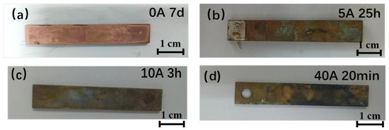
Figure 1.
Macroscopic morphology of Cu with corrosion products after being immersed under different current densities. (a) 0 A; (b) 5 A; (c) 10 A; (d) and 40 A.
3.2. Corrosion Product Analysis
The Raman spectra of the surface corrosion products of Cu immersed in a simulated atmospheric environment with different currents are shown in Figure 2. The results of Raman spectroscopy analysis showed that the corrosion products were Cu2O, CuO, and Cu2Cl(OH)3. The color of Cu2Cl(OH)3 is green, which is similar to the results of macroscopic morphology observation. When the applied current is 0 A, 5 A, and 10 A, the corrosion products are mainly CuO, Cu2O, and Cu2Cl(OH)3. When the applied current increases to 40 A, the number of Raman characteristic peaks of Cu corrosion products decreases.
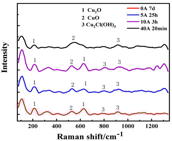
Figure 2.
Raman spectra of Cu being immersed under different current conditions.
Figure 3 shows the microscopic morphology of Cu under different current conditions. Among them, the bottom surface marked as 1 is the microscopic morphology, and the bottom surface marked as 2 is the 3D morphology. According to the 3D micro-morphology, the corrosion of Cu is very slight, and on the surface of Cu appears to be a small amount of corrosion products when no current electric field is applied. When currents of 5, 10, and 40 A are applied, more corrosion pits appear on the surface, accompanied by a small amount of corrosion products. And with the increase of current, the corrosion becomes more serious.
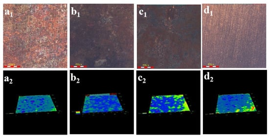
Figure 3.
Micro-morphology of Cu with corrosion products after immersed under different current densities: (a1,a2) 0 A-7 d; (b1,b2) 5 A-25 h; (c1,c2) 10 A-3 h; (d1,d2) and 40 A-20 min.
In order to further clarify the effect of an applied current on the extent of Cu corrosion, the corrosion rate was calculated. Figure 4 shows the corrosion rates of Cu under the different current field conditions. It can be seen from Figure 4 that when no current field condition is applied, the corrosion rate of copper is the smallest, which is 3.88 mm·y−1. When the applied current is 5 A, the corrosion rate of copper increases to 8.74 mm·y−1. This is because the application of a current causes the electrode potential to deviate from its equilibrium potential, making copper more prone to losing electrons and undergoing oxidation. In addition, the presence of an electric current promotes the migration of ions in the solution, thereby accelerating corrosion. When the applied current is 10 A, the corrosion rate of copper decreases. It might be that the corrosion products on the surface of the sample play a certain protective role. As shown in Figure 2, the corrosion products on the copper surface are Cu2O, CuO, and Cu2Cl(OH)3. Among them, Cu2O has the characteristics of P-type semiconductors and low-level electronic conductivity. It forms a protective film on the copper surface, preventing Cl− and OH− from further reacting with the substrate, providing a certain protective effect on the substrate. Under the action of a high current of 40 A, the corrosion rate significantly increases to 832.82 mm·y−1. Under the action of a large current, the corrosion product film on the copper surface is severely damaged, and at this time, the anode and cathode reactions are also significantly accelerated.
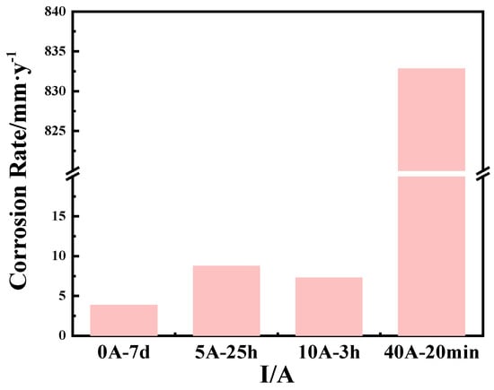
Figure 4.
Corrosion rate of Cu under different current field conditions. (0 A-7 d; 5 A-25 h; 10 A-3 h; and 40 A-20 min).
3.3. Electrochemical Analysis
Figure 5 presents the electrochemical impedance spectra of Cu after various immersion times under different current conditions, where Figure 5a–c shows Nyquist plots and Figure 5d–f shows Bode plots. It can be seen from Figure 5a–c that the capacitive reactance arc radius of Cu first increased, and then decreased with the increase in immersion time under the currents of 0 A, 5 A, and 10 A. This is due to the formation of a corrosion product film on the surface at the beginning of corrosion. And the corrosion product film was damaged to a certain extent at the later stage. The ability of the corrosion product film to impede charge transfer was reduced, thus the corrosion rate increased.
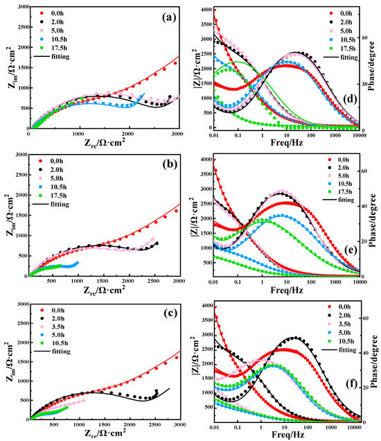
Figure 5.
EIS of Cu being immersed in 3.5 wt% NaCl solution with different current field conditions and periods: (a,d) 0 A; (b,e) 5 A; (c,f) and 10 A.
In order to further analyze the electrochemical impedance spectra, the data were fitted using the equivalent circuit shown in Figure 6, where W is Warburg impedance, which was used to determine whether there is diffusion behavior. It can be seen from Table S1 that the charge transfer resistance Rct of Cu increased first, and then decreased with the increase in immersion time under the current conditions of 0 A, 5 A, and 10 A. In the initial stage, corrosion products formed on the surface of Cu. The existence of the corrosion product film may have effectively prevented direct contact between the corrosive medium and the Cu substrate, resulting in an increase in Rct, and thereby slowing down corrosion. This is consistent with the increase in the arc radius of volume resistance capacitance and the enhanced corrosion resistance of Cu in the early stage of corrosion. However, with the increase in immersion time and current intensity, the corrosion product film on the Cu surface becomes progressively damaged, so Rct gradually decreases and corrosion becomes more severe.
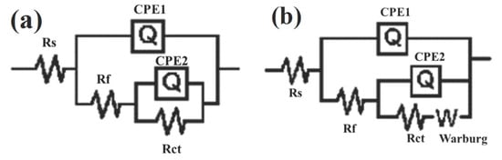
Figure 6.
Equivalent circuit diagram for electrochemical impedance spectrum fitting of Cu. (a) 0 h; (b) Other conditions.
Figure 7 shows the polarization curves of Cu at 0 A, 5 A, and 10 A, respectively. The anode reaction is the dissolution of Cu, and the cathode reaction is oxygen reduction. It can be seen that with the increase in immersion time, the corrosion potential under the 0 A and 10 A applied currents shifts negatively, and the corrosion potential decreases first, and then increases under the 5 A applied current. The magnitude of the corrosion potential reflects the corrosion tendency of metal; the larger the corrosion potential is, the smaller the corrosion tendency of metal is. The corrosion current density was fitted, and the results are shown in Table 2. The size of the corrosion current density is closely related to the corrosion rate. Table 2 shows that the anodic dissolution of Cu was accelerated, and ion migration might also be accelerated with an increasing current. The corrosion current density of Cu shows a trend of decreasing first, and then increasing with an increase in immersion time under the three different current conditions. This was due to the formation of a corrosion product film on the surface in the early corrosion stage. The corrosion product film, with some protective properties, led to a reduction in the corrosion rate. However, with the destruction of the corrosion product film, the Cu substrate was re-exposed, leading to an increased corrosion rate.
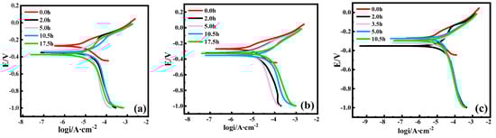
Figure 7.
Polarization curves of Cu immersed in 3.5 wt% NaCl solution with different current field conditions and periods. (a) 0 A; (b) 5 A; (c) and 10 A.
Table 2.
Polarization parameters of Cu being immersed in different current field conditions and periods.
4. Discussion
Whether the corrosion products have certain protective properties depends on their structural characteristics. The higher the porosity is, the looser the corrosion product film is; the lower the porosity is, the denser it is relatively. The electrochemical corrosion process of Cu in the 3.5 wt% NaCl solution is as follows [23,24]:
The corrosion products on its surface are mainly Cu2O, CuO, and Cu2Cl(OH)3. Among them, Cu2O has a better protective effect due to its characteristics of a P-type semiconductor and low-level electronic conductivity.
The EIS results show that regardless of whether an applied current exists or not, the corrosion resistance of the Cu specimens immersed in the 3.5 wt% NaCl solution first increases, and then decreases as the immersion time prolongs. This situation is related to the corrosion products formed during the corrosion process. In the initial stage of immersion, the corrosion product film formed on the surface of the Cu specimen has a certain protective effect. It can prevent corrosion media such as Cl− and OH− from coming into direct contact with the substrate, providing a certain degree of protection for the base material and inhibiting corrosion. With the further progress of corrosion, these protective corrosion products will crack or dissolve, and corrosion can reoccur. In addition, the presence of an applied current will also have an impact on the types of corrosion product, as shown in Figure 2. When the applied current increases, electron transfer on the surface of copper accelerates, and copper atoms are more likely to lose electrons and transform into Cu(II) ions that enter the solution. Therefore, the number of Raman peaks of Cu2O decreases. The changes in the corrosion rate of the Cu specimen under the different applied currents are shown in Figure 4. When the applied current increases from 0 A to 5 A, the corrosion rate increases. However, when the applied current is 10 A, the corrosion rate decreases. At 40 A, the corrosion rate increases significantly. Generally, when an external current is applied to a metal, the electrode potential of the anode shifts positively, making it easier for metal atoms to lose electrons and accelerating the electrochemical corrosion process. At the same time, after more metal ions enter the solution, the formation rate of corrosion products is also affected, leading to changes in their structural properties. At the same time, after more metal ions enter the solution, the formation rate of corrosion products is also affected, leading to changes in their structural properties. On the other hand, the presence of a large current will damage the protective film, causing the metal to lose its protection and be directly exposed to the corrosive medium, thus accelerating corrosion.
5. Conclusions
(1) In 3.5 wt% NaCl solution, copper forms corrosion products, such as Cu2O, CuO, and Cu2Cl(OH)3. These compounds remain dominant at applied currents of 0 A, 5 A, and 10 A. However, when the current increases to 40 A, the number of Raman peaks of Cu2O decrease. Copper in a solution appears to corrode uniformly and becomes thinner as the current increases.
(2) The corrosion rate of copper escalates with higher applied currents, increasing from 3.88 mm·y−1 at 0 A to 832.82 mm·y−1 at 40 A. This acceleration occurs because the current enhances both cathodic and anodic reactions, while disrupting the protective corrosion product film.
(3) Electrochemical analysis reveals that at a fixed current, charge transfer resistance (Rct) initially rises, and then declines with prolonged immersion, while the corrosion current density (Icorr) follows an inverse trend, first decreasing, and then increasing. This behavior indicates that the corrosion product film provides temporary protection before deteriorating. Furthermore, comparing different currents shows that Rct decreases and Icorr increases with higher applied currents, confirming that the electrical current exacerbates corrosion.
Supplementary Materials
The following supporting information can be downloaded at: https://www.mdpi.com/article/10.3390/coatings15091036/s1, Table S1: EIS fitting results of Cu immersed in 3.5 wt% NaCl solution with different current field conditions and periods.
Author Contributions
Conceptualization, Z.F.; methodology, B.D.; validation, B.J.; formal analysis, Z.G.; investigation, Y.W.; resources, Q.W.; funding acquisition, Z.F. All authors have read and agreed to the published version of the manuscript.
Funding
The State grid Shandong Electric power company technology project 2023A-199.
Institutional Review Board Statement
Not applicable.
Informed Consent Statement
Not applicable.
Data Availability Statement
All the data included in this article are available upon request by contact the corresponding author.
Acknowledgments
The authors wish to acknowledgement the financial support from the State grid Shandong Electric power company.
Conflicts of Interest
No conflict of interest exits in the submission of this manuscript.
References
- Niu, D.; Shi, H.; Li, J. Research of Evaluation Index System of the Development and Construction of “Two-type Transformer Substation”. J. Sustain. Dev. 2010, 3. [Google Scholar] [CrossRef][Green Version]
- Tong, Z.; Dong, Z.; Ashton, T. Analysis of electric field influence on buildings under high-voltage transmission lines. IET Sci. Meas. Technol. 2016, 10, 253–258. [Google Scholar] [CrossRef]
- Bender, R.; Féron, D.; Mills, D.; Ritter, S.; Bäßler, R.; Bettge, D.; De Graeve, I.; Dugstad, A.; Grassini, S.; Hack, T.; et al. Corrosion challenges towards a sustainable society. Mater. Corros. 2022, 73, 1730–1751. [Google Scholar] [CrossRef]
- Chen, J.; Liu, J.; Wang, H.; Li, B.; Hu, Q.; Shao, T.; Yang, R.; Wang, B.; Wan, Q.; Li, Z.; et al. Experimental Study on Neutral Salt Spray Accelerated Corrosion of Metal Protective Coatings for Power-Transmission and Transformation Equipment. Coatings 2023, 13, 480. [Google Scholar] [CrossRef]
- Ajmal, C.M.; Benny, A.P.; Jeon, W.; Kim, S.; Kim, S.W.; Baik, S. In-situ reduced non-oxidized copper nanoparticles in nanocomposites with extraordinary high electrical and thermal conductivity. Mater. Today 2021, 48, 59–71. [Google Scholar] [CrossRef]
- Sato, M.; Endo, S.; Bu, Y.; Mizuno, T. Effectiveness of Magnetic Composite Material on Copper Loss Reductions and Misalignment in Copper-Plate-Coils for Wireless Power Transmission. IEEJ Trans. Electr. Electron. Eng. 2021, 16, 470–477. [Google Scholar] [CrossRef]
- King, F.; Lilja, C.; Vähänen, M. Progress in the understanding of the long-term corrosion behaviour of copper canisters. J. Nucl. Mater. 2013, 438, 228–237. [Google Scholar] [CrossRef]
- Shinato, K.W.; Zewde, A.A.; Jin, Y. Corrosion protection of copper and copper alloys in different corrosive medium using environmentally friendly corrosion inhibitors. Corros. Rev. 2020, 38, 101–109. [Google Scholar] [CrossRef]
- Wu, J. Understanding the electric double-layer structure, capacitance, and charging dynamics. Chem. Rev. 2022, 122, 10821–10859. [Google Scholar] [CrossRef]
- Kirchner, K.; Kirchner, T.; Ivaništšev, V.; Fedorov, M. Electrical double layer in ionic liquids: Structural transitions from multilayer to monolayer structure at the interface. Electrochim. Acta 2013, 110, 762–771. [Google Scholar] [CrossRef]
- Zhang, P.; Li, W.; Li, S.; Wang, Y.; Xiao, W. Reliability assessment of photovoltaic power systems: Review of current status and future perspectives. Appl. Energy 2013, 104, 822–833. [Google Scholar] [CrossRef]
- Dong, K.; Song, Y.; Chang, F.; Han, E.H. Galvanic corrosion mechanism of Ti-Al coupling: The impact of passive films on the coupling effect. Electrochim. Acta 2023, 462, 142662. [Google Scholar] [CrossRef]
- Cheng, T.; Huang, H.; Huang, G. Galvanic corrosion behavior between ADC12 aluminum alloy and copper in 3.5 wt% NaCl solution. J. Electroanal. Chem. 2022, 927, 116984. [Google Scholar] [CrossRef]
- Zhang, X.; Zhang, J.; Dai, N.; Yang, Y.; Yuan, X.; Cao, F.; Zhang, J. Probing the corrosion mechanism of zinc under direct current electric field. Mater. Chem. Phys. 2018, 206, 232–242. [Google Scholar] [CrossRef]
- Gu, J.; Xiao, Y.; Dai, N.; Zhang, X.; Ni, Q.; Zhang, J. The Suppression of transformation of γ-FeOOH to α-FeOOH accelerating the steel corrosion in simulated industrial atmospheric environment with a DC electric field interference. Corros. Eng. Sci. Technol. 2019, 54, 249–256. [Google Scholar] [CrossRef]
- Chen, Y.; Yang, Y.; Zhang, J.; Zhang, X.; Dai, N.; Zhang, L.C. Influence of direct current electric field on electrode process of carbon steel under thin electrolyte layers. J. Electrochem. Soc. 2018, 165, C385. [Google Scholar] [CrossRef]
- Dai, N.; Zhang, J.; Chen, Q.; Yi, B.; Cao, F.; Zhang, J. Effect of the direct current electric field on the initial corrosion of steel in simulated industrial atmospheric environment. Corros. Sci. 2015, 99, 295–303. [Google Scholar] [CrossRef]
- Su, G.; Ding, D.; Li, C.; Du, C.; Liu, Z.; Yang, X. Short-term Corrosion Behavior of Q235 Steel and Cu with AC Interference in Beijing Soil with Different Soil Moisture Contents. Corros. Prot. 2016, 37, 613–617+626. [Google Scholar] [CrossRef]
- Huang, H.; Guo, X.; Zhang, G.; Dong, Z. Effect of direct current electric field on atmospheric corrosion behavior of copper under thin electrolyte layer. Corros. Sci. 2011, 53, 3446–3449. [Google Scholar] [CrossRef]
- Huang, H.; Pan, Z.; Guo, X.; Qiu, Y. Effect of an alternating electric field on the atmospheric corrosion behaviour of copper under a thin electrolyte layer. Corros. Sci. 2013, 75, 100–105. [Google Scholar] [CrossRef]
- Huang, H.; Guo, X.; Zhang, G.; Dong, Z. The effects of temperature and electric field on atmospheric corrosion behaviour of PCB-Cu under absorbed thin electrolyte layer. Corros. Sci. 2011, 53, 1700–1707. [Google Scholar] [CrossRef]
- GB/T16545-1996; Corrosion of Metals and Alloys—Removal of Corrosion Products from Corrosion Test Specimens. State Administration for Market Regulation: Beijing, China, 1996.
- Huang, H.; Pan, Z.; Qiu, Y.; Guo, X. Electrochemical corrosion behaviour of copper under periodic wet–dry cycle condition. Microelectron. Reliab. 2013, 53, 1149–1158. [Google Scholar] [CrossRef]
- Lin, H.; Frankel, G.S. Atmospheric corrosion of Cu during constant deposition of NaCl. J. Electrochem. Soc. 2013, 160, C336. [Google Scholar] [CrossRef]
Disclaimer/Publisher’s Note: The statements, opinions and data contained in all publications are solely those of the individual author(s) and contributor(s) and not of MDPI and/or the editor(s). MDPI and/or the editor(s) disclaim responsibility for any injury to people or property resulting from any ideas, methods, instructions or products referred to in the content. |
© 2025 by the authors. Licensee MDPI, Basel, Switzerland. This article is an open access article distributed under the terms and conditions of the Creative Commons Attribution (CC BY) license (https://creativecommons.org/licenses/by/4.0/).