Article

Experimental Study on Anti-Crystallization Performance of Tunnel Drainage Pipes Based on Magnetic Powder Effect

1
POLY Changda Engineering Co., Ltd., Guangzhou 511431, China
2
Institute of Future Civil Engineering Science and Technology, Chongqing Jiaotong University, Chongqing 400074, China
3
College of Civil Engineering, Chongqing Jiaotong University, Chongqing 400074, China
*
Author to whom correspondence should be addressed.
Coatings 2025, 15(9), 1005; https://doi.org/10.3390/coatings15091005 (registering DOI)
Submission received: 18 July 2025 / Revised: 21 August 2025 / Accepted: 26 August 2025 / Published: 30 August 2025
(This article belongs to the Section Environmental Aspects in Colloid and Interface Science)

Abstract

Tunnel drainage pipes are prone to blockage due to mineral crystallization and deposition from water, which seriously affects the long-term stable operation of the drainage system and compromises the safety of tunnel structures. To address this issue, it is imperative to develop efficient anti-crystallization technologies to extend the service life of drainage systems. In this study, a series of anti-crystallization performance experiments on tunnel drainage pipes were designed and conducted based on magnetic treatment technology. The inhibitory effects of magnetic fields on crystal formation and deposition were systematically investigated under various conditions, including different magnetic field intensities, magnetic field coverage angles, magnetic field orientations, and water flow velocities. The results indicate that under magnetic influence, the crystal morphology inside the pipes changed from regular cubic structures to irregular forms with rough surfaces and loose structures, showing a transformation trend from calcite to aragonite and vaterite. Compared with conventional PVC pipes, the anti-crystallization effect was most pronounced under the following conditions: magnetic field intensity of 40 Gs, coverage angle of 90°, vertical magnetic field orientation, and higher water flow velocity. The findings of this study provide a novel approach to mitigating crystallization-induced blockages in tunnel drainage systems and contribute to reducing tunnel-related pathologies such as lining cracks, water seepage, and structural deterioration caused by poor drainage.

1. Introduction

In recent years, with the continuous advancement of transportation infrastructure construction, the number of newly built tunnels in China has been increasing, and the scale of tunnels in operation has expanded significantly. Consequently, various tunnel-related pathologies have gradually emerged [1,2,3], severely affecting driving safety and comfort [4]. Among them, crystallization-induced blockage in tunnel drainage systems has become increasingly prominent. As a common, concealed, and persistent issue, it poses a significant threat to the load-bearing capacity and durability of tunnel structures. Crystallization blockage not only leads to the degradation of drainage functionality but may also trigger secondary problems such as lining cracks and water leakage [5,6,7], thereby endangering the structural safety of the tunnel.
At present, research on crystallization blockage in tunnel drainage systems primarily focuses on its material sources, formation mechanisms, and influencing factors. Investigations have shown that the main component of the blockage inside tunnel drainage pipes is typically calcium carbonate (CaCO3) [8,9]. The Ca2+ ions in the drainage system mainly originate from groundwater, surface water, fractured surrounding rock water, and shotcrete [10,11,12]. After entering the drainage system, Ca2+ ions interact with CO2 in the air and carbonate (CO32−) or bicarbonate (HCO3) ions in the solution under the influence of multiple factors such as temperature, pH, and pressure, forming CaCO3 crystals that gradually deposit and harden, eventually causing blockages in drainage pipes, blind drains, and other components [13,14,15].
To address this issue, researchers both in China and abroad have explored a variety of prevention and control technologies. Dietzel et al. [16] proposed the use of high-pressure equipment to flush drainage pipes, while Xu et al. [17] suggested cleaning crystalline deposits in aging tunnels using environmentally friendly acid agents composed of SA, water, and additives. However, due to the concealed nature of tunnel structures, complex environmental conditions, and the uncertainty of crystallization locations, these remediation methods often suffer from low efficiency and prolonged treatment cycles. As a result, increasing attention has shifted toward optimizing drainage system materials and reducing crystal formation at the source. In terms of source control, optimizing the mix design of shotcrete [18] and improving drainage system configurations [19] can reduce the release of Ca2+ ions. Regarding material optimization, many scholars have employed physical or chemical approaches—such as electric fields [20,21], magnetic fields [21,22], acoustic waves [23,24], and surface coatings [25,26]—to modify the inner surface of drainage pipes, thereby inhibiting crystal adhesion. In addition, green inhibitors such as polyaspartic acid (PASP) [27], lime mortar–carboxymethyl cellulose [28], and phosphoprotein–casein complexes [29] have been shown to influence the nucleation of calcium carbonate, altering the morphology and growth behavior of crystals through promotion or inhibition mechanisms. Although these methods have shown effectiveness, each has limitations: chemical inhibitors may raise environmental and durability concerns, surface coatings can fail under complex hydrochemical conditions, and physical fields (e.g., electric or acoustic) face challenges of stability and cost at scale. In contrast, magnetic treatment is a non-contact, environmentally friendly, and potentially sustainable approach. Magnetic particles can induce fields that continuously regulate crystallization, avoiding the drawbacks of chemical and coating methods. Nevertheless, systematic studies on key parameters such as field strength, effective range, and orientation remain limited, hindering large-scale engineering applications.
This study systematically investigates the influence of magnetic fields on the nucleation and adhesion behavior of crystalline substances within drainage pipes through laboratory experiments and numerical simulations. Specifically, the research explores the optimal magnetic field parameters by varying magnetic field coverage, intensity, orientation, and water flow rate to evaluate their effects on crystal nucleation rate and crystal quantity. In addition, based on numerical simulations, the study analyzes the distribution of magnetic field lines under different coverage conditions, further validating the optimal range of magnetic field applications. The proposed approach introduces a novel anti-crystallization technique that offers a new strategy for mitigating crystallization in tunnel drainage systems.

2. Experimental Design

2.1. Experimental Materials and Apparatus

2.1.1. Preparation of Magnetic Drainage Pipes

The NdFeB magnetic slurry was prepared using a mass ratio of magnetic powder, epoxy resin, coupling agent, and curing agent of 1:(0.8–0.9):(0.15–0.2):(0.12–0.15). The epoxy resin and curing agent used in this study were supplied by Hunan Brother New Materials Co., Ltd. (DeyI DY-6012 epoxy resin and its corresponding curing agent, Daming Industrial Park, Jinxia Economic Development Zone, Changsha, China). The coupling agent was a titanate-based product provided by Nanjing Chuangshi Chemical Additives Co., Ltd. (Nanjing, China). The epoxy curing agent reacts with the epoxy and hydroxyl groups in the epoxy resin through addition or catalytic polymerization, thereby crosslinking the linear polymer chains into a three-dimensional network structure. The titanate coupling agent was employed to improve the interfacial compatibility between Nd-Fe-B magnetic powders and the epoxy resin matrix, thus enhancing the overall performance of the composite material. The preparation procedure was as follows: first, epoxy resin was placed into a container, followed by the sequential addition of NdFeB magnetic powder and coupling agent. The mixture was thoroughly stirred to ensure uniform dispersion of the magnetic powder in the resin matrix under the action of the coupling agent. The curing agent was then added, and the mixture was stirred continuously to maintain homogeneity.
During the pipe treatment process, the surface of the PVC drainage pipe was first polished using sandpaper in the designated coating areas. The prepared NdFeB slurry was then evenly applied to one side of the pipe. After complete curing, the other side was coated. Once the entire coating process was finished and fully cured, the PVC pipe was magnetized to achieve the target magnetic field intensity.
Since the magnetic field strength on the inner wall of the PVC pipe after magnetization is closely related to the amount of magnetic powder applied, multiple sets of drainage pipe samples with varying magnetic powder dosages were prepared in this study. The magnetic field intensity of each sample was subsequently measured. The relationship between magnetic powder mass and corresponding magnetic field strength is shown in Figure 1.

2.1.2. Test Solution and Apparatus Design

Analysis of tunnel groundwater samples revealed that the water contains relatively high concentrations of cations, primarily Ca2+ and Mg2+, and a high concentration of the anion HCO3. Under alkaline conditions, HCO3 readily converts to CO32−, which facilitates the formation of CaCO3 crystals through combination with Ca2+. To ensure that the ionic concentrations under alkaline conditions meet the experimental requirements [30,31], a supersaturated solution was prepared using anhydrous calcium chloride (CaCl2) and anhydrous sodium bicarbonate (NaHCO3).
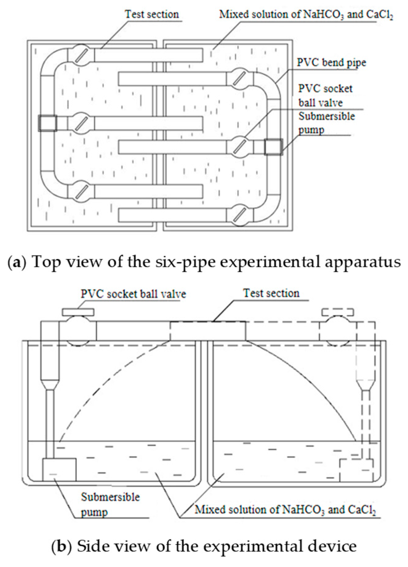
The laboratory test setup adopted a dual-tank symmetric circulation system, as shown in Figure 2. The system mainly consists of a magnetically treated PVC test pipe section, plastic water tanks, and a water circulation system. The circulation system includes a submersible pump, PVC connecting pipes, reducing joints, 3D tee joints, and socket ball valves.

2.2. Experimental Plan

2.2.1. Crystallization Behavior Under Different Magnetic Field Coverage Angles

(1) Experimental Scheme
Magnetic drainage pipe samples with a fixed magnetic field intensity of 30 Gs and magnetic field coverage angles of 45°, 90°, and 135° were prepared. A smooth PVC pipe of equal length was used as a control group. Each test section was installed in the circulating water system with a consistent water flow rate and a vertically oriented magnetic field. During the experiment, a pre-prepared supersaturated calcium chloride–sodium bicarbonate solution was added to the water tanks to evaluate the effects of different magnetic field coverage angles on crystallization behavior. Each test cycle lasted for 7 days. At the end of each cycle, the test sections were removed, drained, and weighed to record the amount of crystalline deposition. They were then reinstalled immediately to begin the next cycle. This process was repeated until the experiment was complete.
(2) Simulation validation
① Boundary conditions
The simulation considered the material properties of NdFeB magnetic powder, PVC drainage pipe, and air. Given the thin pipe wall (approximately 1 mm) and its minimal effect on magnetic field penetration, the PVC wall was modeled as air, with corresponding parameters (see Table 1). The relative permeability listed in Table 1 is defined as the ratio of a material’s magnetic permeability to that of vacuum. Based on relevant data and experimental results, the fundamental relationship between coercive force and magnetic field intensity was established (see Table 2).
② Computational model
The magnetic field coverage angle was treated as the independent variable, with magnetic field intensity fixed at 30 Gs. Three finite element models were established to simulate magnetic slurry distributions of 45°, 90°, and 135° on the upper and lower sides of the pipe, in order to study the effect of distribution range on the internal magnetic field. Using the material properties and coercivity–field intensity relationship from Table 2 and Table 3, the coercive force was set to 300,000 A/m, and the relative permeability for both PVC and air was set to 1. Finite element types used included PLANE53 (2D magnetic field elements) and INFINITE9 (infinite far-field elements). The outermost infinite boundary was assigned AZ boundary conditions to constrain the magnetic flux lines within the XY plane. The magnetic field intensity was fixed at 30 Gs, and coverage angles were set at 45°, 90°, and 135°. Meshes were generated freely (see Figure 3).
This simulation aimed to validate the spatial distribution of the magnetic field from multiple perspectives, thereby supporting the scientific basis of the experimental findings and ensuring the reliability and validity of subsequent data.

2.2.2. Crystallization Behavior Under Different Magnetic Field Intensities

Based on the relationship between magnetic powder mass and field intensity (Figure 1), magnetic drainage pipe samples were prepared with magnetic field intensities of 30 Gs, 40 Gs, and 50 Gs. A smooth PVC pipe of the same length served as the control group. All test pipes were installed in the water circulation system with a fixed magnetic field coverage of 90°, vertical magnetic field orientation, and uniform water flow rate. A supersaturated calcium chloride–sodium bicarbonate solution was added to the tanks to investigate the influence of magnetic field intensity on crystallization behavior. Each cycle lasted 7 days. At the end of each cycle, pipe sections were removed, drained, and weighed to determine the amount of crystalline deposition, then reinstalled for the next cycle until the experiment concluded.

2.2.3. Crystallization Behavior Under Different Flow Rates and Magnetic Field Orientations

Magnetic drainage pipe samples were prepared based on the parameters in Table 3 and installed in the circulating water system. A supersaturated calcium chloride–sodium bicarbonate solution was added to the tanks. Experiments were conducted under different magnetic field orientations (using pipe sections 2, 3, and 6) and different water flow rates (using sections 1, 4, 5, and 6). Each test cycle lasted 7 days. At the end of each cycle, pipe segments were removed, drained, and weighed for crystalline deposition, and then reinstalled for the subsequent cycle until the experiment was complete.

3. Experimental Results and Discussion

3.1. Effect of Magnetic Field Coverage Angle on Crystallization Behavior in Tunnel Drainage Pipes

3.1.1. Analysis of Laboratory Test Results

As shown in Figure 4, in the magnetic drainage pipes, the magnetic slurry coated on the upper and lower sides acts as two arc-shaped strip magnets, with the magnetic field near their edges being particularly pronounced. When the magnetic field coverage angle is 90°, the edges of the magnetic slurry are closer to the main water flow inside the pipe, allowing the magnetic field to more effectively cover the flow. In contrast, the 45° configuration provides a limited coverage area, leaving part of the flow outside the magnetic field influence. Although the 135° configuration fully covers the cross-section of the flow, the water primarily passes through the central region of the magnetic slurry, where the magnetic field intensity is weaker than in the 90° configuration. Overall, the 90° coverage range demonstrated superior anti-crystallization performance compared to 45° and 135°.
As illustrated in Figure 5a,b, during the first test cycle, the crystallization accumulation curves for all conditions increased steeply. In the untreated pipe, the accumulated crystalline mass grew rapidly from the first to the fourth cycle. In contrast, the magnetic field-treated pipes showed a leveling off in their accumulation curves starting from the third cycle. From cycle 1 to cycle 2, the incremental crystallization decreased by 32.7%, 60.6%, and 11.5% for the 45°, 90°, and 135° configurations, respectively. From cycle 2 to cycle 3, the reductions were 66.0%, 28.6%, and 50.8%, respectively. During the final three cycles, the growth in accumulated crystallization further slowed and eventually stabilized. These results indicate that magnetic fields can effectively regulate the crystallization process inside drainage pipes, significantly reducing the crystallization rate. Among the three configurations, the 90° magnetic field coverage most effectively inhibited crystal growth and deposition.
As shown in Figure 5c, the total accumulated crystallization increased over time across all test conditions. Compared to the magnetic field-treated pipes, the untreated pipe exhibited higher crystalline accumulation by 40.9%, 146.6%, and 21.8% than the 45°, 90°, and 135° configurations, respectively.
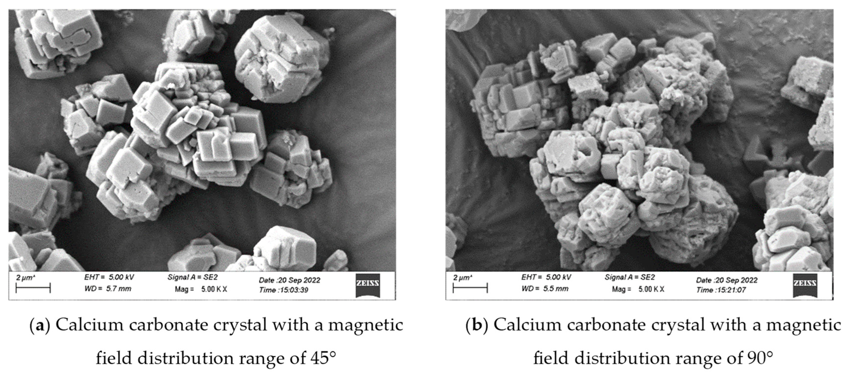
Figure 6 shows that the magnetic field coverage angle had a significant impact on the morphology of calcium carbonate crystals. Under 45° and 90° magnetic fields, the crystals gradually transformed from regular cube-like and lamellar morphologies into irregular block-shaped forms, and eventually evolved toward spherical morphologies. Fine particles and pores appeared on previously smooth crystal surfaces [32,33]. Overall, the crystal mass formed under the 90° configuration was significantly lower—by 42.9% and 50.6%—than those formed under the 45° and 135° configurations, respectively.

3.1.2. Numerical Simulation Validation

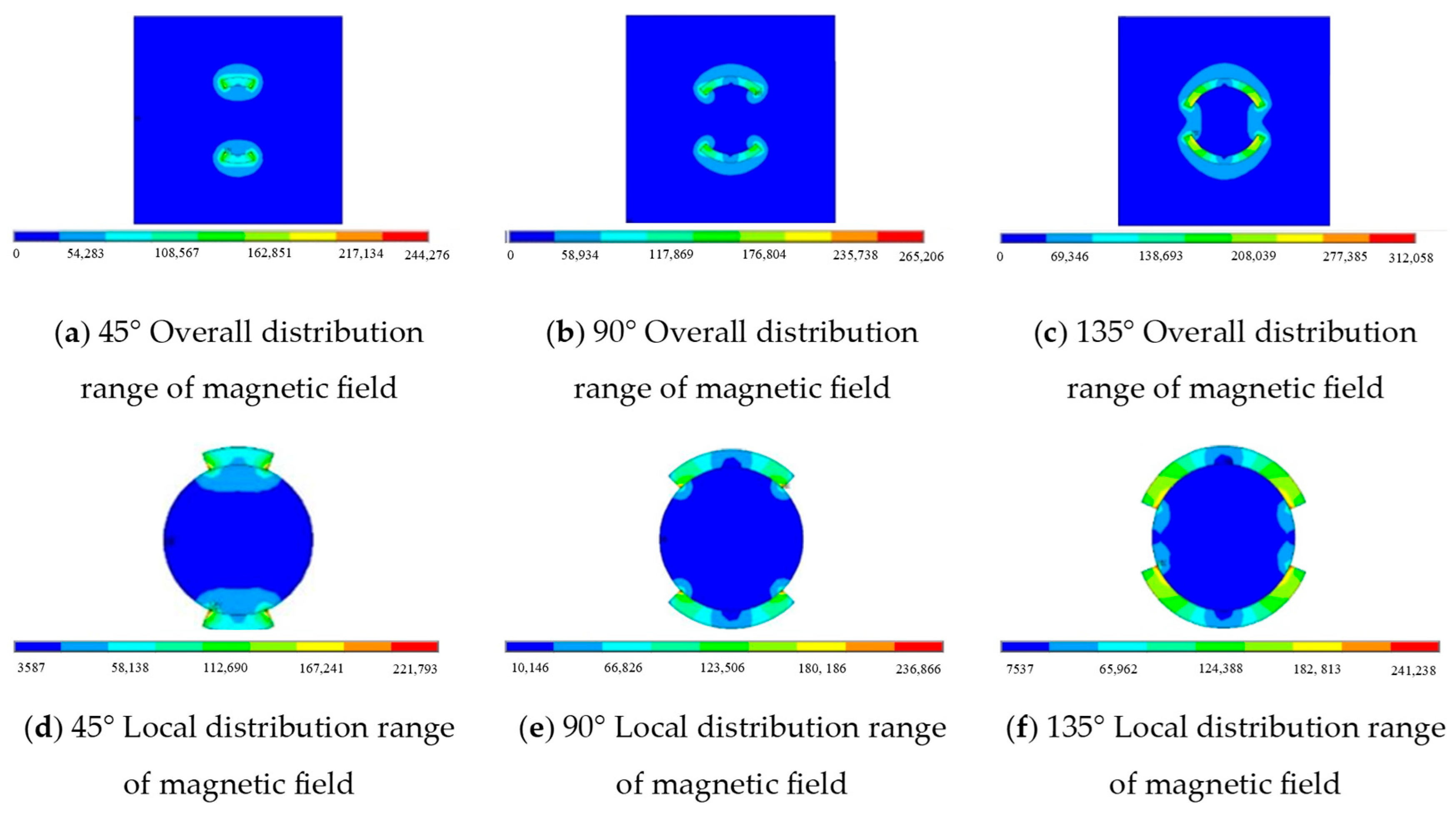
As shown in Figure 7, under different magnetic field coverage conditions, the magnetic field intensity within the drainage pipe is not uniformly distributed. Regions near the edges of the magnetic slurry exhibit higher magnetic field intensities, whereas regions farther away show weaker fields. When the magnetic field coverage angle is 90°, both the pipe wall and the pipe center experience stronger magnetic fields compared to the 45° and 135° configurations (see Figure 8). Specifically, under the 45° condition, the magnetic field intensity at the pipe center is only 3.58 Gauss, while it reaches 30.86 Gs at the pipe wall—nearly an eightfold difference. For the 90° and 135° configurations, the center-to-wall magnetic field intensity ratios are approximately 4:1 and 5:1, respectively.
As illustrated in Figure 9, these disparities primarily stem from the geometric characteristics of the arc-shaped magnet structure. In the 90° and 135° models, the regions with the densest magnetic flux lines are located at the ends of the magnets. Since these ends are relatively far from the upper and lower walls of the pipe, the magnetic field lines in those regions are sparse, resulting in weaker magnetic fields. In addition, the magnet ends exhibit a phenomenon similar to “edge enhancement” or “tip discharge,” where the mutual repulsion between the north and south poles intensifies magnetism at the edges, concentrating the magnetic flux lines. Consequently, under the 90° magnetic field distribution, the internal magnetic force within the pipe is more balanced and pronounced.

3.2. Influence of Magnetic Field Intensity on Crystallization Behavior in Tunnel Drainage Pipes

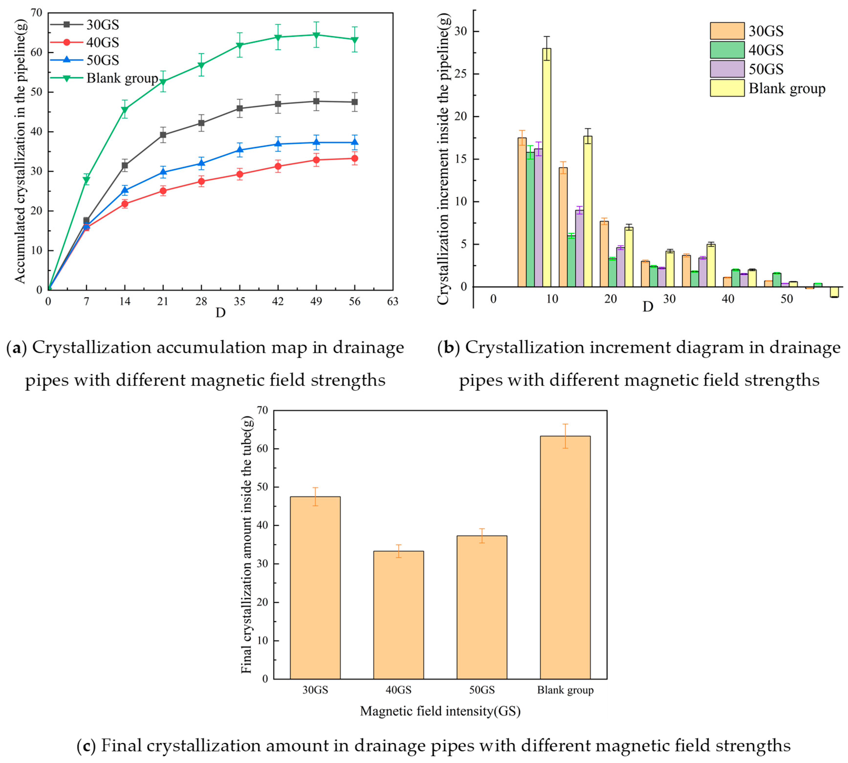
As shown in Figure 10a,b, during the first test cycle, the accumulated crystallization in all magnetically treated drainage pipe samples was nearly identical and significantly lower than that in the untreated pipe. From the second cycle onward, differences emerged among the magnetic treatment groups. Between cycle 1 and cycle 2, the percentage decrease in crystallization increment was 20.0%, 62.0%, and 44.4% for the 30 Gs, 40 Gs, and 50 Gs magnetic field intensities, respectively, while the untreated pipe showed a 36.7% reduction. Over the following four cycles, the crystallization growth rate gradually slowed across all groups, with the accumulation stabilizing in the final three cycles. These results indicate that the magnetic field significantly reduced crystallization accumulation by affecting the nucleation and growth processes of calcium carbonate within the pipe. Among the tested intensities, the 40 Gs magnetic field exhibited superior anti-crystallization performance compared to 30 Gs and 50 Gs.
As shown in Figure 10c, the overall crystallization accumulation increased over time across all groups. Compared with the magnetically treated groups, the untreated pipe exhibited 33.3%, 90.1%, and 69.7% more crystallization than the 30 Gs, 40 Gs, and 50 Gs samples, respectively. Among the treated samples, the pipe with a 40 Gs magnetic field showed the lowest crystallization accumulation, with reductions of 29.9% and 10.7% compared to the 30 Gs and 50 Gs groups, respectively.
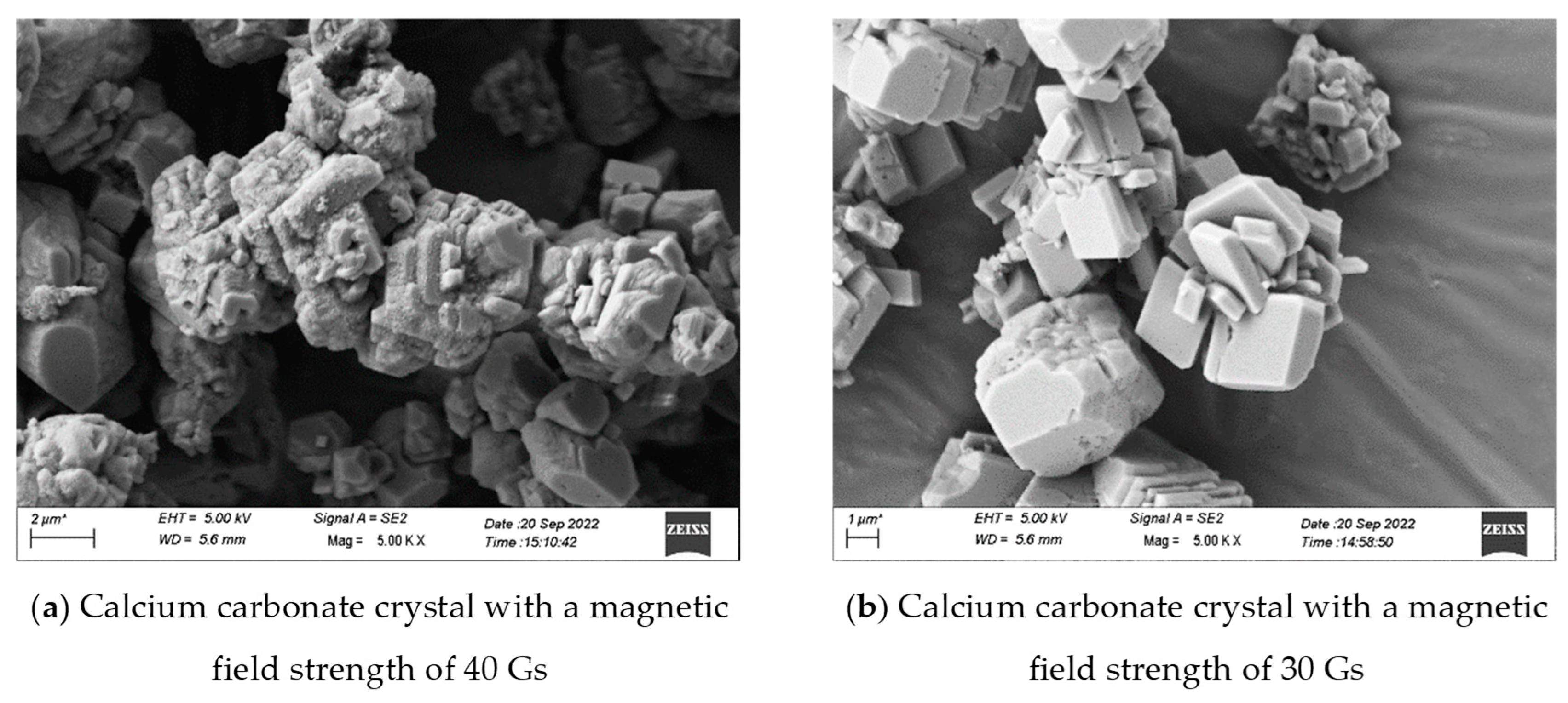
Figure 11 illustrates that magnetic field intensity has a notable effect on crystal morphology. Under the 40 Gs magnetic field, calcium carbonate crystals transitioned from dense calcite to looser aragonite and even vaterite structures [34,35], thereby reducing their deposition rate and adhesion strength.

3.3. Influence of Magnetic Field Orientation on Crystallization Behavior in Tunnel Drainage Pipes

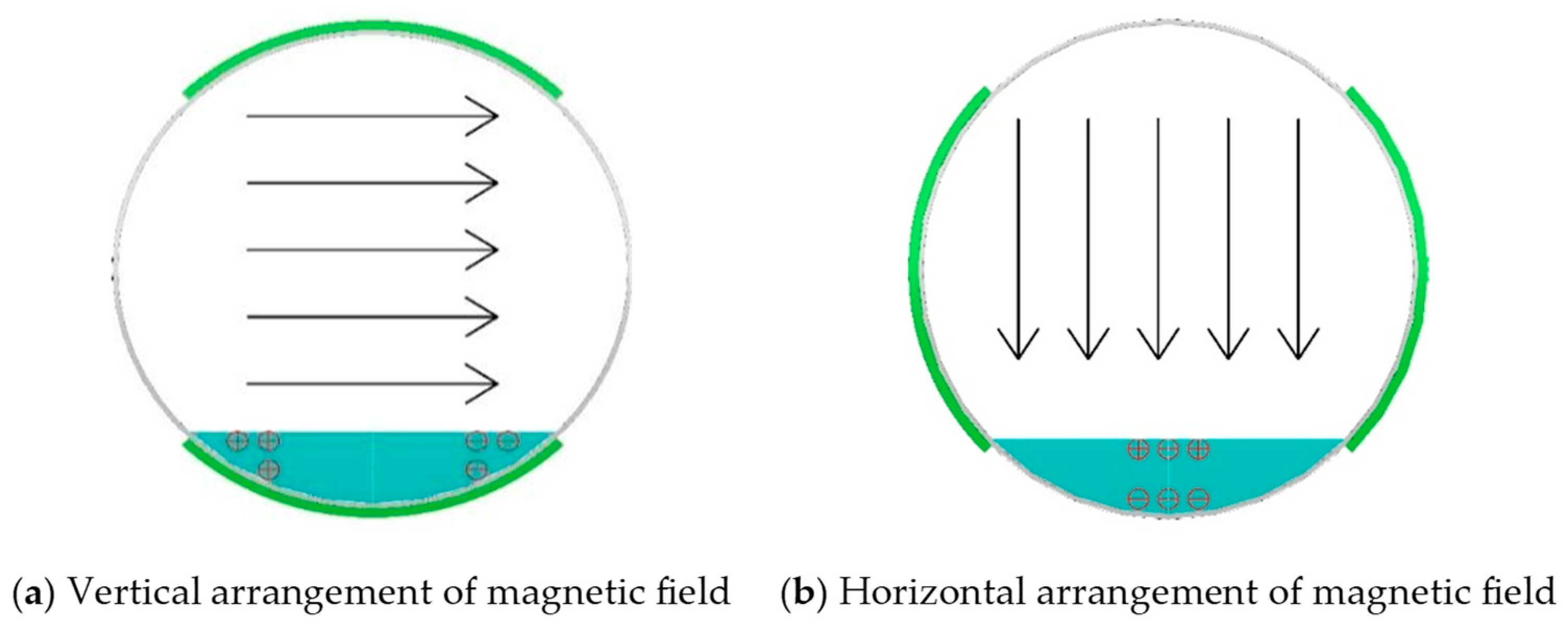
As shown in Figure 12, when the magnetic field is arranged horizontally, the magnetic slurry is coated on the left and right sides of the pipe, resulting in a magnetic force direction that is vertical (up–down) within the pipe. Consequently, the motion trajectories of ions in the solution also follow a vertical direction. In contrast, when the magnetic field is arranged vertically, the slurry is applied to the upper and lower sides of the pipe, generating a horizontal (left–right) magnetic force, and the ionic trajectories shift accordingly to a lateral direction.
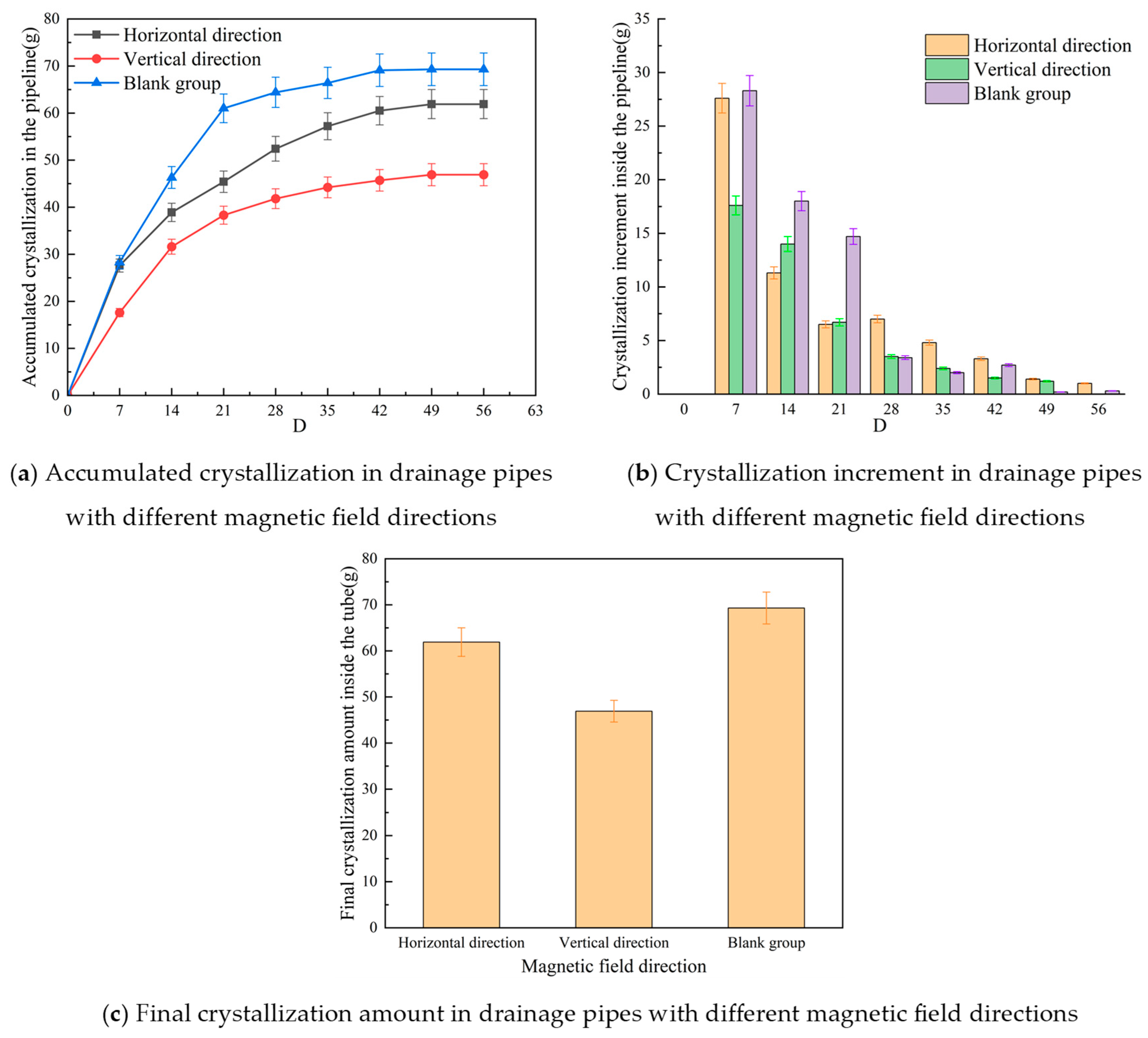
As shown in Figure 13a,b, the accumulated crystallization increased rapidly during the first two test cycles. From cycle 1 to cycle 2, the crystallization increment decreased by 59.1% and 20.5% under horizontal and vertical magnetic fields, respectively. From cycle 2 to cycle 3, the reduction rates were 42.5% and 52.1%, respectively. In the final three cycles, the accumulation rate gradually slowed and eventually stabilized, showing little variation.
As illustrated in Figure 13c, the untreated drainage pipe exhibited significantly higher crystallization accumulation than the two magnetically treated groups—47.8% higher than the vertical orientation group and 12.0% higher than the horizontal orientation group. Additionally, compared to horizontal orientation, vertical magnetic field arrangement reduced crystallization accumulation by 24.2%.
These results indicate that magnetic field orientation plays a critical role in determining crystallization behavior. Vertically oriented magnetic fields more effectively disturb ion distribution within the water flow, thereby reducing deposition rates. This configuration is superior to horizontal arrangements in preventing crystallization-induced blockage.

3.4. Influence of Internal Flow Rate on Crystallization Behavior in Tunnel Drainage Pipes

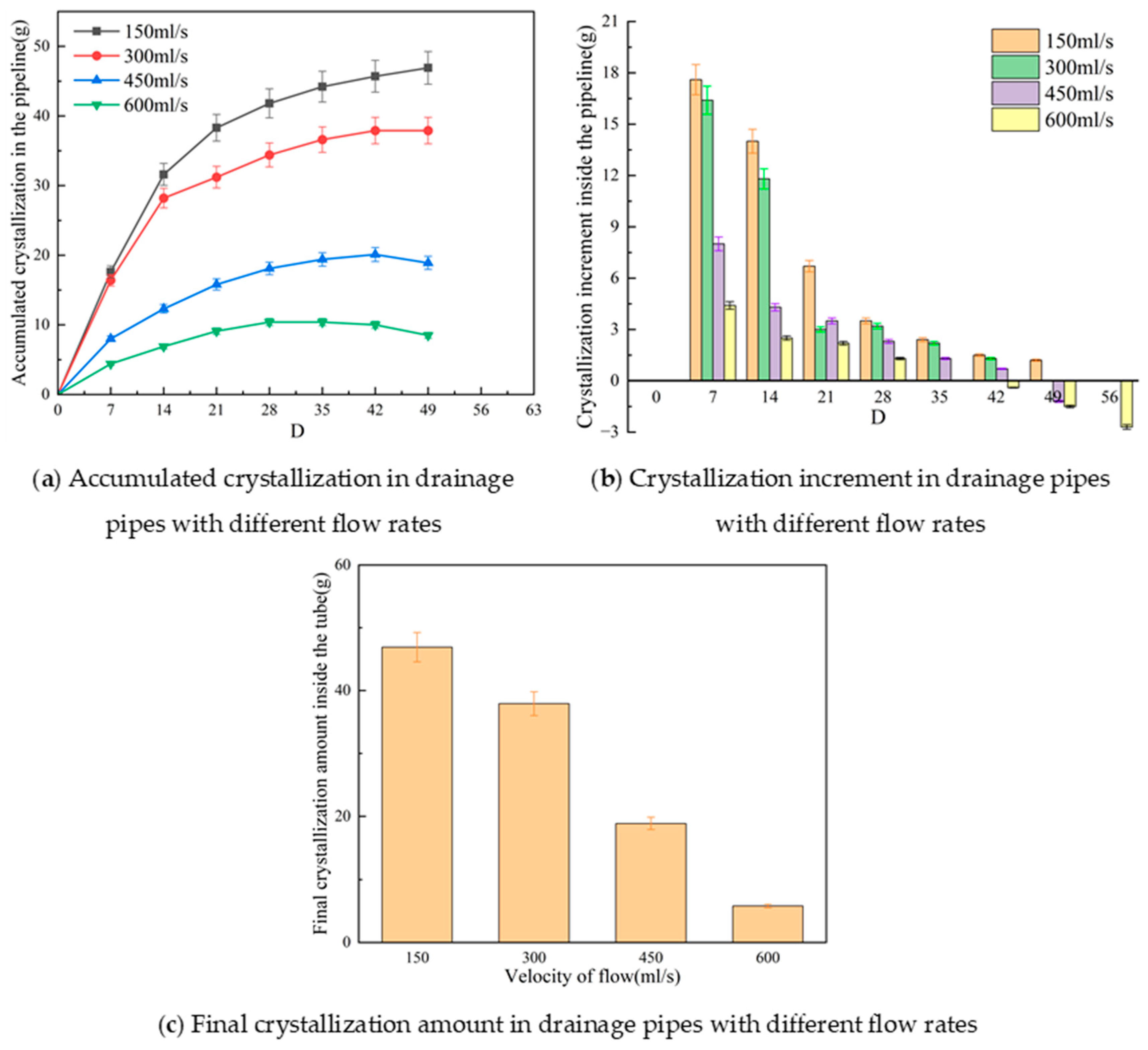
As shown in Figure 14a,b, under flow rates of 150 mL/s and 300 mL/s, the trend of crystallization accumulation closely resembled the patterns observed under varying magnetic field intensities, coverage angles, and orientations. During the first two test cycles, crystallization increased rapidly, followed by a slower growth rate from the third cycle onward, eventually reaching a stable state. However, under higher flow rates of 450 mL/s and 600 mL/s, the crystallization behavior diverged significantly from the lower flow rate conditions. In the first four cycles, the accumulation increased only slowly and then plateaued, even showing slight decreases thereafter. These results suggest that when the flow rate reaches 450 mL/s or a certain threshold value, it becomes difficult for stable crystal deposits to form within the drainage pipe. As the flow rate increases further, the overall crystallization accumulation continues to decline. However, once a critical flow velocity is surpassed, the influence of flow rate on crystallization becomes negligible.
As shown in Figure 14c, under a flow rate of 150 mL/s, the total accumulated crystallization was significantly higher than that observed under other flow rate conditions. Specifically, crystallization at 150 mL/s exceeded that at 300 mL/s, 450 mL/s, and 600 mL/s by 23.7%, 148.1%, and 708.6%, respectively.
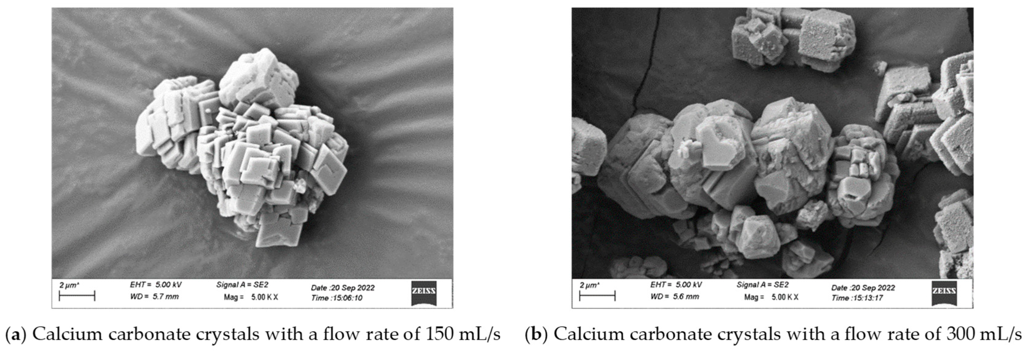
As depicted in Figure 15, with increasing flow velocity, the morphology of calcium carbonate crystals changed from dense and well-ordered to loose and sparse. The originally regular stacking arrangement between crystals was disrupted, and irregular particles appeared between fine grains, leading to the formation of irregular crystal agglomerates [36,37,38]. Therefore, with higher flow rates, the overall crystallization accumulation in the pipe gradually declined. At a flow rate of 600 mL/s, hardly any noticeable crystallization was observed inside the pipe.

4. Conclusions

Through laboratory-scale model experiments and numerical simulations, this study verified the feasibility of using magnetic drainage pipes to prevent crystallization-induced blockage in tunnel drainage systems. It also systematically investigated the effects of magnetic field intensity, coverage angle, orientation, and flow rate on anti-crystallization performance. The main conclusions are as follows:
(1) Laboratory results demonstrated that the anti-crystallization effect was most pronounced when the magnetic field intensity was 40 Gs, the coverage angle was 90°, and the magnetic field was vertically oriented.
(2) Under magnetic field influence, the morphology of CaCO3 crystals gradually transformed from regular cubic and lamellar forms into irregular cubic shapes, evolving toward spherical structures. Fine particles and pores emerged on the crystal surfaces, and the overall accumulation pattern became looser and sparser. Therefore, magnetic treatment effectively reduces both crystal formation and adhesion.
(3) Numerical simulations confirmed the influence of magnetic field coverage angle on anti-crystallization performance. In the 90° and 135° models, which resemble arc-shaped magnets, enhanced magnetism at both ends was observed due to tip-like field enhancement and repulsion between the internal north and south poles. Among these, the 90° configuration exhibited the densest magnetic flux lines and superior mitigation effect, with an overall trend of performance ranked as 90° > 135° > 45°.
(4) Flow rate had a significant impact on crystallization accumulation. Under a flow rate of 150 mL/s, the accumulated crystallization was 23.7%, 148.1%, and 708.6% higher than that under 300 mL/s, 450 mL/s, and 600 mL/s, respectively. This indicates that crystallization significantly decreases as flow rate increases. However, beyond a certain threshold, the rate of decline levels off and becomes less noticeable.
This study, based on the principle of the magnetic particle effect, investigated the anti-crystallization performance of magnetic particles in tunnel drainage systems and clarified the influence patterns of certain magnetic particle parameters on crystallization resistance. It should be noted that the long-term stability of magnetic particles, as well as variations in water chemistry (such as pH, ion concentration, and the critical role of Mg2+ in aragonite formation), may significantly affect their anti-crystallization performance. These factors will be explored in greater depth in future research. In addition, material development and optimization will be conducted with the consideration of cost factors in order to further reduce application costs and enhance the feasibility and practical value of this technology in large-scale engineering applications.

Author Contributions

Conceptualization, S.L. and C.W.; software, C.W.; formal analysis, D.X.; writing—original draft preparation, D.X., B.L. and X.Y.; writing—review and editing, K.H., W.W. and S.L. All authors have read and agreed to the published version of the manuscript.

Funding

This research received no external funding.

Institutional Review Board Statement

Not applicable.

Informed Consent Statement

Not applicable.

Data Availability Statement

Data is contained within the article.

Conflicts of Interest

Author Donghui Xiao, Benhua Liu, Kun Huang and Wenzhen Wu were employed by the company POLY Changda Engineering Co., Ltd. The remaining authors declare that the research was conducted in the absence of any commercial or financial relationships that could be construed as a potential conflict of interest.

References

  1. Xu, S.; Ma, E.; Lai, J.; Yang, Y.; Liu, H.; Yang, C.; Hu, Q. Diseases failures characteristics and countermeasures of expressway tunnel of water-rich strata: A case study. Eng. Fail. Anal. 2022, 134, 106056. [Google Scholar] [CrossRef]
  2. Tan, Z.; Li, S.; Yang, Y.; Wang, J. Large deformation characteristics and controlling measures of steeply inclined and layered soft rock of tunnels in plate suture zones. Eng. Fail. Anal. 2022, 131, 105831. [Google Scholar] [CrossRef]
  3. Yoo, C. Hydraulic deterioration of geosynthetic filter drainage system in tunnels–its impact on structural performance of tunnel linings. Geosynth. Int. 2016, 23, 463–480. [Google Scholar] [CrossRef]
  4. Seki, S.; Kaise, S.; Morisaki, Y.; Azetaka, S.; Jiang, Y. Model experiments for examining heaving phenomenon in tunnels. Tunn. Undergr. Space Technol. 2008, 23, 128–138. [Google Scholar] [CrossRef]
  5. Zhang, S.; Xu, Q.; Yoo, C.; Min, B.; Liu, C.; Guan, X.; Li, P. Lining cracking mechanism of old highway tunnels caused by drainage system deterioration: A case study of Liwaiao Tunnel, Ningbo, China. Eng. Fail. Anal. 2022, 137, 106270. [Google Scholar] [CrossRef]
  6. Xu, Q.; Zhang, S.; Li, P.; Liu, C.; Bao, T. Lining failure performance of highway tunnels induced by the drainage system deterioration. Eng. Fail. Anal. 2023, 149, 107236. [Google Scholar] [CrossRef]
  7. Xu, C.; Chen, Y.; Yang, Y.; Li, P.; Wang, S.; Li, L. Experimental Investigation of Crystal Blocking in Drainage Pipes for Tunnels in the Karst Region. Appl. Sci. 2022, 12, 10928. [Google Scholar] [CrossRef]
  8. Jung, H.; Han, Y.; Chung, S.; Chun, B.; Lee, Y. Evaluation of advanced drainage treatment for old tunnel drainage system in Korea. Tunn. Undergr. Space Technol. 2013, 38, 476–486. [Google Scholar] [CrossRef]
  9. Jiang, Y.; Tong, Y.; Ye, F.; Zhang, J.; Tian, C.; Wu, B.; Cui, H. The failure mechanism of crystallization blockage in tunnel drainage system and preventive measure of scale inhibitor. Eng. Fail. Anal. 2024, 166, 108915. [Google Scholar] [CrossRef]
  10. Galan, I.; Baldermann, A.; Kusterle, W.; Dietzel, M.; Mittermayr, M. Durability of shotcrete for underground support–Review and update. Constr. Build. Mater. 2019, 202, 465–493. [Google Scholar] [CrossRef]
  11. Sun, M.; Cao, J.; Cao, J.; Zhang, S.; Chen, Y.; Bate, B. Discrete element modeling of shear wave propagation in carbonate precipitate–Cemented particles. Acta Geotech. 2022, 17, 2633–2649. [Google Scholar] [CrossRef]
  12. Eichinger, S.; Boch, R.; Leis, A.; Koraimann, G.; Grengg, C.; Domberger, G.; Nachtnebel, M.; Schwab, C.; Dietzel, M. Scale deposits in tunnel drainage systems–A study on fabrics and formation mechanisms. Sci. Total Environ. 2020, 718, 137140. [Google Scholar] [CrossRef]
  13. Wang, Y.D.; Liu, Y.; Qi, C.F.; Zhou, T.Y.; Ye, M.; Wang, T. Crystallization law of karst water in tunnel drainage system based on DBL theory. Open Phys. 2021, 19, 241–255. [Google Scholar] [CrossRef]
  14. Liu, D.G.; Yang, Y.; Mao, C.J.; Wu, J.F.; Wu, J.C. A comparative study on hydrodynamics and hydrochemistry coupled simulations of drainage pipe crystallization blockage in karst tunnels. J. Earth Sci. 2022, 33, 1179–1189. [Google Scholar] [CrossRef]
  15. Zhao, K.; Yu, B.; Yang, Y.; Li, S.; Li, D. Causes, influencing factors, and prediction modeling of crystallization blockage of tunnel drainage blind pipe in non-karst area. Case Stud. Constr. Mater. 2024, 21, e04041. [Google Scholar] [CrossRef]
  16. Dietzel, M.; Rinder, T.; Leis, A.; Reichl, P.; Sellner, P.; Draschitz, C.; Plank, G.; Klammer, D.; Schofer, H. Koralm tunnel as a case study for sinter formation in drainage systems–Precipitation mechanisms and retaliatory action. Geomech. Tunnelbau Geomech. Tunnelbau 2008, 1, 271–278. [Google Scholar] [CrossRef]
  17. Xu, Z.; Wang, X.; Zhang, C.; Zeng, D.; Liu, C. Scaling and clogging treatment of aging tunnel drainage pipes in karst areas using eco-friendly acid agent. J. Rock Mech. Geotech. Eng. 2023, 15, 896–910. [Google Scholar] [CrossRef]
  18. Tian, C.; Tong, Y.; Zhang, J.; Ye, F.; Song, G.; Jiang, Y.; Zhao, M. Experimental study on mix proportion optimization of anti-calcium dissolution shotcrete for tunnels based on response surface methodology. Undergr. Space 2024, 15, 203–220. [Google Scholar] [CrossRef]
  19. Lin, Z.; Liu, K.; Zhang, X.; Chen, X.; Xie, P.; Tan, Y. Optimizations for tunnel drainage water system based on locations of crystallizations. Desalination Water Treat. 2023, 299, 232–238. [Google Scholar] [CrossRef]
  20. Wei, L.; Guo, J.; Zhang, X.; Li, Y.; Huang, H. Study of electric field impact on crystallization in tunnel drainage pipes in hard water area. Adv. Civ. Eng. 2021, 2021, 5584229. [Google Scholar] [CrossRef]
  21. Hou, Z.; Liu, Q.; Sun, Y.; Han, F.; Zhang, J.; Liu, S.; Liu, Z. Influence of Electromagnetic Field on Crystallization of Tunnel Drainage Pipes. J. Appl. Sci. Eng. 2022, 26, 517–527. [Google Scholar]
  22. Leng, H.; Lv, H.; Han, F.; Liu, F.; Liu, T. Permanent magnet treatment technology for crystal blockage of tunnel drainage pipes. Desalination Water Treat. 2021, 243, 211–220. [Google Scholar] [CrossRef]
  23. Xin, Z.; Moon, J.H.; Kim, Y.U. Reduction of adherent forces of sedimentous contaminants in tunnel drainage using vibrations from flexible and transparent organic films. KSCE J. Civ. Eng. 2018, 22, 2619–2622. [Google Scholar] [CrossRef]
  24. Xin, Z.; Moon, J.H.; Kim, Y.U. Effect of vibration of flexible transducer on shear resistance of scaling in tunnel drainage. KSCE J. Civ. Eng. 2017, 21, 1929–1932. [Google Scholar] [CrossRef]
  25. Jiang, Y.; Zhang, J.; Ye, F.; Tong, Y.; Tian, C.; Li, Y. Anti-crystallisation coating for tunnel drainage system: Investigation, experiment, and mechanism. Eng. Fail. Anal. 2024, 157, 107903. [Google Scholar] [CrossRef]
  26. Zhou, Y.; Zhang, X.; Wei, L.; Liu, S.; Zhang, B.; Zhou, C. Experimental study on prevention of calcium carbonate crystallizing in drainage pipe of tunnel engineering. Adv. Civ. Eng. 2018, 2018, 9430517. [Google Scholar] [CrossRef]
  27. Eichinger, S.; Boch, R.; Leis, A.; Baldermann, A.; Domberger, G.; Schwab, C.; Dietzel, M. Green inhibitors reduce unwanted calcium carbonate precipitation: Implications for technical settings. Water Res. 2022, 208, 117850. [Google Scholar] [CrossRef]
  28. Liu, H.; Zhao, Y.; Peng, C.; Song, S.; López-Valdivieso, A. Lime mortars–The role of carboxymethyl cellulose on the crystallization of calcium carbonate. Constr. Build. Mater. 2018, 168, 169–177. [Google Scholar] [CrossRef]
  29. Liu, Y.; Cui, Y.J.; Mao, H.Y.; Guo, R. Calcium carbonate crystallization in the presence of casein. Cryst. Growth Des. 2012, 12, 4720–4726. [Google Scholar] [CrossRef]
  30. Liu, S.; Zhang, X.; Chen, X.; Wang, C.; Chen, Y. Exploratory Research on Drainage Structure of Highway Tunnel Based on Reducing the Risk of Crystallization Blockage. Processes 2022, 10, 1319. [Google Scholar] [CrossRef]
  31. Liu, S.; Zhang, X. Fault Diagnosis and Maintenance Countermeasures of Transverse Drainage Pipe in Subway Tunnel Based on Fault Tree Analysis. Int. J. Environ. Res. Public Health 2022, 19, 15471. [Google Scholar] [CrossRef]
  32. Goncharuk, V.V.; Bagrii, V.A.; Bashtan, S.Y. Crystallization of calcium carbonate from aqueous solutions in superimposition of electric and magnetic fields. J. Water Chem. Technol. 2012, 34, 133–135. [Google Scholar] [CrossRef]
  33. Mahmoud, B.; Yosra, M.; Nadia, A. Effects of magnetic treatment on scaling power of hard waters. Sep. Purif. Technol. 2016, 171, 88–92. [Google Scholar] [CrossRef]
  34. Sohaili, J.; Shi, H.S.; Zardari, N.H.; Ahmad, N.; Muniyandi, S.K. Removal of scale deposition on pipe walls by using magnetic field treatment and the effects of magnetic strength. J. Clean. Prod. 2016, 139, 1393–1399. [Google Scholar] [CrossRef]
  35. Latifa, S.B.; Cheap-Charpentier, H.; Perrot, H.; Amor, Y.B. Effects of magnetic field on homogeneous and heterogeneous precipitation of calcium carbonate. ChemElectroChem 2023, 10, e202300105. [Google Scholar] [CrossRef]
  36. Turner, C.W.; Smith, D.W. Calcium carbonate scaling kinetics determined from radiotracer experiments with calcium-47. Ind. Eng. Chem. Res. 1998, 37, 439–448. [Google Scholar] [CrossRef]
  37. Xu, X.; Zhang, Y.; Li, L.; Xu, C.B. Model test on crystallization law of tunnel drainage pipe in karst area. Highw. Traffic Sci. Technol. 2022, 39, 133–139. [Google Scholar]
  38. Lv, J.; Wu, H.; Li, J.; Wan, X.; Fu, H. Analysis of Fouling Pattern of Tunnel Drainage Pipe in Karst Areas. Adv. Civ. Eng. 2023, 2023, 8881333. [Google Scholar] [CrossRef]
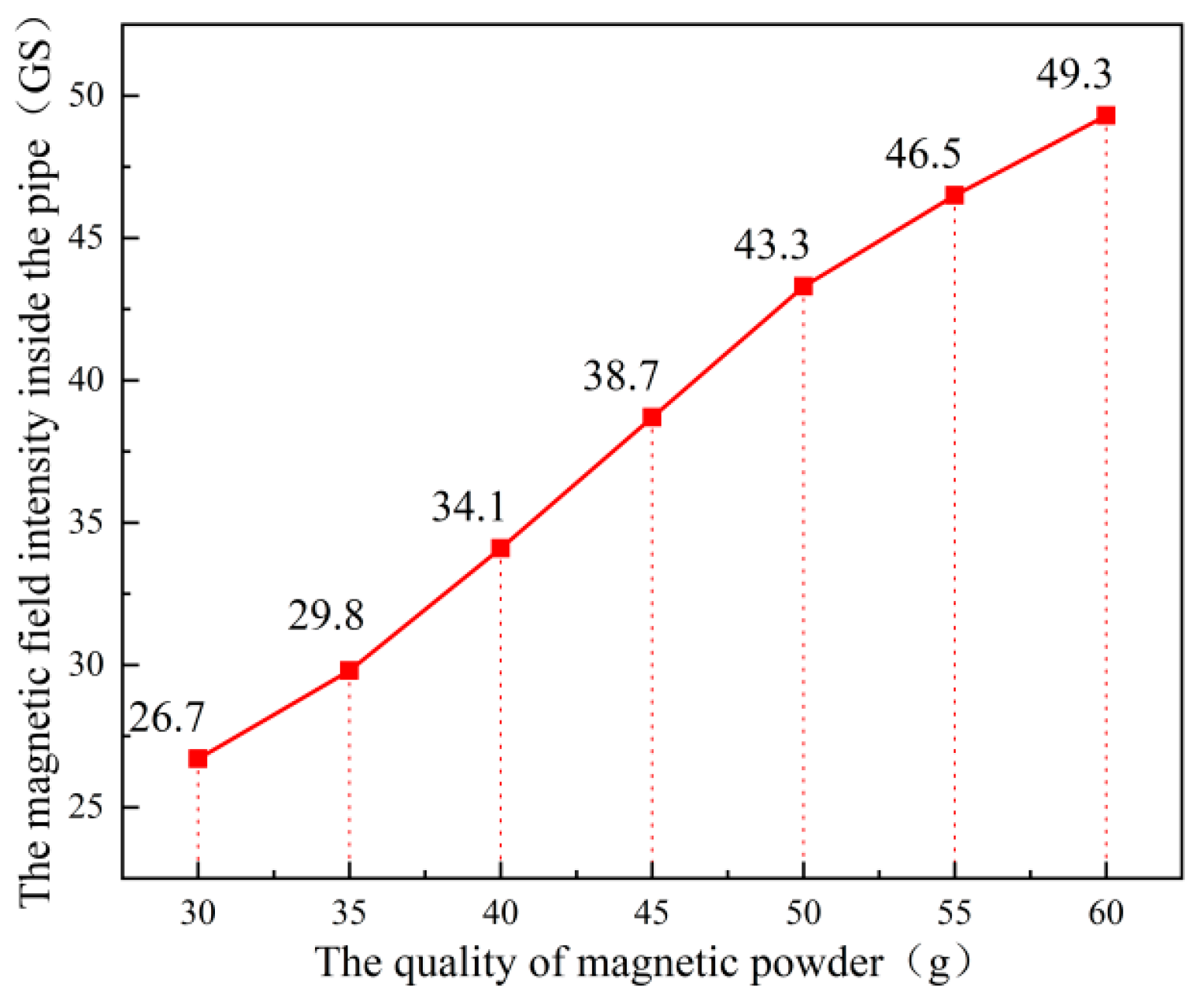
Figure 1. Relationship between magnetic powder mass and internal magnetic field intensity of PVC pipe after magnetization.
Coatings 15 01005 g001
Figure 2. Experimental system design diagram.
Coatings 15 01005 g002
Figure 3. Grid division model for different magnetic field distribution ranges.
Coatings 15 01005 g003
Figure 4. Model diagram of relative position of water flow in drainage pipes under different magnetic field distribution ranges.
Coatings 15 01005 g004
Figure 5. Crystallization changes inside tunnel drainage pipes under different magnetic field distribution ranges.
Coatings 15 01005 g005
Figure 6. Microscopic image of calcium carbonate crystal structure. Microscopic images of the crystal structure of calcium carbonate under different magnetic field distributions.
Coatings 15 01005 g006
Figure 7. Cloud map of magnetic field strength for different magnetic field distribution ranges.
Coatings 15 01005 g007
Figure 8. Relationship between magnetic field strength and magnetic field distribution range.
Coatings 15 01005 g008
Figure 9. Local magnetic field lines in different magnetic field distribution ranges.
Coatings 15 01005 g009
Figure 10. Crystallization changes inside tunnel drainage pipes under different magnetic field strengths.
Coatings 15 01005 g010
Figure 11. Microscopic images of calcium carbonate crystals under different magnetic field strengths.
Coatings 15 01005 g011
Figure 12. Movement trajectories of anions and cations in pipelines under different magnetic field directions.
Coatings 15 01005 g012
Figure 13. Crystallization changes in tunnel drainage pipes under different magnetic field directions.
Coatings 15 01005 g013
Figure 14. Crystallization changes in tunnel drainage pipes under different flow rates.
Coatings 15 01005 g014
Figure 15. Microscopic images of calcium carbonate crystals at different flow rates.
Coatings 15 01005 g015
Table 1. Material parameters table.
Simulation MaterialsRelative PermeabilityCoercivity (A/m)
Air1-
Neodymium iron–boron magnetic powder1.05220,000 (220 Gs)
Table 2. Relationship between coercivity and magnetic field strength.
Coercivity (A/m)Magnetic Field Intensity (Gs)
30,00030
40,00040
50,00050
Table 3. Test conditions under different flow rates and magnetic field directions.
WorkingTest Section NumberMagnetic Field Intensity (Gs)Distribution Range (°)Magnetic Field DirectionWater Flow Rate
(mL/s)
Condition
Water Tank
A13090vertical direction600
200-150
33090Horizontal direction150
B43090vertical direction450
53090vertical direction300
63090vertical direction150
Disclaimer/Publisher’s Note: The statements, opinions and data contained in all publications are solely those of the individual author(s) and contributor(s) and not of MDPI and/or the editor(s). MDPI and/or the editor(s) disclaim responsibility for any injury to people or property resulting from any ideas, methods, instructions or products referred to in the content.