Abstract
Slurry-based additive manufacturing (AM) enables the fabrication of dense and complex ceramic components through the layer-by-layer deposition of high-solid-content slurries. However, the reliable formation of uniform, defect-free slurry layers remains a bottleneck for process stability and final part quality. In this study, the slot-die coating window for alumina slurry (50 wt%, viscosity = 34 Pa·s) was systematically investigated using volume-of-fluid simulations and experiments, with coating speed (0.7–2.8 mm/s), flow rate (0.6–0.8 mL/min), and coating gap (200–400 μm) as key variables. The coating process exhibited three distinct regimes, namely overflow, stable, and unstable, depending on process conditions. For a coating gap of 200 μm on a glass substrate, stable bead formation was observed over the widest coating speed range without overflow or air entrainment. At higher speeds, dynamic wetting failure induced air entrainment and bead breakage, while lower speeds led to overflow defects. When coating on a dried alumina layer (contact angle, CA = 137), the stable window narrowed significantly compared to the glass substrate (CA = 66.7, highlighting the substantial influence of substrate wettability on coating stability and defect formation. The results derived in this work offer practical guidance for optimizing process parameters to achieve uniform, defect-free films in multilayer ceramic AM.
1. Introduction
Ceramic materials have been widely used due to their high hardness, wear resistance, chemical stability, and high-temperature performance. However, due to their inherent brittleness, shaping complex ceramic components by conventional machining is challenging [1]. Additive manufacturing (AM) offers a solution by building parts layer-by-layer, enabling complex geometries without subtractive machining [2]. Current ceramic AM technologies can be broadly classified by feedstock form into two categories: (1) powder-based processes such as binder jetting (BJ) and selective laser sintering/melting (SLS/SLM), which spread dry ceramic powder layers and selectively bind or fuse them [3]; and (2) slurry-based processes that deposit a suspension of ceramic particles (slurry) in each layer (e.g., vat photopolymerization like stereolithography (SLA) or digital light processing (DLP), as well as material extrusion (ME) [4,5]. Powder-based methods benefit from well-established machinery but suffer from low packing density in the powder bed (often <50 vol% solid) [6]. Such poor initial packing leads to low density of green body and large shrinkage upon sintering, resulting in a weak or distorted final sintered body. For example, SLS/SLM of ceramics is limited to relatively coarse powders and can introduce thermal stresses and cracks due to the use of lasers [7]. Photopolymer-based slurry printing (SLA/DLP) allows finer particles, but the required organic resin content limits the ceramic fraction (typically <50vol% solids) [8,9,10].
To overcome these limitations, slurry-based AM techniques have been actively explored to increase packing density and improve sintered properties. Early pioneering work by Cima et al. [11] at MIT introduced a slurry-based 3D printing process that used fine ceramic suspensions instead of dry powder. This approach achieved green densities around ~58–60% of theoretical and ultimately ~99.9% of theoretical density after sintering, a remarkable improvement over powder-based methods. For instance, alumina parts printed with a high-solids slurry showed a green density of ~58% and sintered to virtually full density (99.9%). Grau et al. [12] demonstrated that layering of fine alumina slurry could yield green densities in the 60–67% range, drastically reducing the shrinkage and porosity in the final ceramic. More recently, Zocca et al. [13] developed the Layerwise Slurry Deposition (LSD) method as a novel route to build ceramic parts with high density. In LSD, a thin layer of ceramic slurry is spread (e.g., by a doctor blade) and dried to form a highly packed powder layer, which can then be selectively bonded by binder jetting in a manner similar to BJ printing. This combined process, so-called “LSD-print,” has been successfully applied to alumina and other ceramics. Lima et al. [14] demonstrated 3D printing of porcelain using LSD-print, achieving parts with fine feature resolution, smooth surfaces, and mechanical properties approaching those of traditionally formed porcelain. These advances confirmed that slurry-based AM can produce much denser and stronger ceramic components than powder-bed methods, provided that each slurry layer is uniformly deposited with a high solid loading. However, achieving such uniform layers remains a significant challenge due to the high viscosity and particle segregation tendency of the concentrated slurries. Therefore, the coating technique used for layer deposition plays a critical role in ensuring the reliability of slurry-based ceramic AM processes.
In this context, slot-die coating emerges as an attractive solution for slurry layer deposition. Slot-die coating is a pre-metered method that delivers the slurry through a narrow slot onto the substrate, allowing precise control of the wet film thickness by simply adjusting the flow rate and substrate speed [15]. Unlike a doctor blade method, which relies on gap height and often the fluid’s self-leveling to set the film thickness, slot-die is an active deposition that can produce uniform films, even for high-viscosity suspensions, by maintaining a stable68 coating bead of fluid between the die and substrate. This makes it feasible to coat thin layers of ceramic slurry with minimal variation. Indeed, slot-die coating is widely used in roll-to-roll manufacturing of functional films from printed electronics and displays to solar cells and battery electrodes because it offers excellent uniformity, scalability, and thickness accuracy [16]. Recent studies have also extended slot-die techniques to polymer film additive manufacturing and multi-layer coatings. For instance, Fang et al. [17] investigated slot-die coating of multi-layer polymer LED phosphor films, where each layer must be smooth and free of air bubbles. This work investigated how slot-die process parameters can improve coating quality in functional multi-layer films.
Process parameters of slot-die coating must be controlled within certain limits, the so-called coating window, to avoid defects [18]. If the coating parameters, including coating speed, flow rate, and gap distance, fall outside the stable coating window, various failure modes can occur. At too low a flow rate, the coating bead may collapse or break, leading to incomplete layer coverage. At excessive coating speed or insufficient flow, the liquid can fail to wet the moving substrate fast enough, resulting in air becoming entrained under the film. This typically manifests as air bubbles or uncoated defects in the layer [19]. Chang et al. observed that relatively low-viscosity slurries tend to exhibit ribbing instabilities, whereas beyond a critical viscosity (~0.075 Pa·s), the dominant defect mechanism shifts to air entrainment at high speeds [20]. In practice, running the process at an extremely slow speed can eliminate most defects by keeping the coating bead very stable; however, this is economically impractical for manufacturing. Therefore, identifying a robust operating window (in terms of coater speed, flow rate, and slurry properties) is essential for implementing slot-die coating in ceramic AM. In addition to flow instabilities, slurry-specific issues must be considered: one is dynamic capillary characteristics and wetting on porous surfaces, since in a multilayer process, the freshly deposited slurry may partially infiltrate or re-wet the previously dried layer, affecting the coating uniformity [21]. Another is shear-induced particle migration; under the high shear of slot-die flow, ceramic particles can migrate or segregate, causing concentration gradients in the coated film [22]. Such effects can lead to non-uniform local solid loading or defects like particle agglomeration and must be understood to ensure each layer dries homogeneously. To date, slot-die coating has been predominantly studied in the context of continuous film manufacturing. However, systematic studies on the coating window for ceramic slurries in an AM context are still lacking.
Researchers have been tasked to better understand and expand the stable coating window by analyzing meniscus dynamics. Pan et al. [23] conducted a computational fluid dynamics (CFD) study to systematically evaluate how coating speed, inlet velocity, die lip geometry, and coating gap influence the pressure profile and flow behavior in slot-die coating. Malakhov et al. [24] demonstrated that applying a mild vacuum behind the die lip can suppress air entrainment and lower the minimum flow rate required for continuous coating. Fang et al. [25] explored vortex formation and dynamic contact angle fluctuations in high-viscosity slot-die coatings. Using both CFD simulations and experiments, they demonstrated that vortex patterns near the upstream meniscus can induce dramatic oscillations in the apparent contact angle from 70° to 140°, ultimately leading to air entrainment through capillary instabilities. However, despite these advances, most existing slot-die studies have focused on relatively low-viscosity fluids such as polymer solutions or electrolytic inks. In contrast, ceramic AM involves highly viscous, particle-suspended slurries, for which the interplay between rheology, shear stress distribution, and interfacial behavior, particularly in multilayer deposition, is not yet well understood in the context of slot-die coating.
In this work, we employed CFD modeling to analyze and optimize the slot-die coating of an alumina slurry for ceramic AM. Two substrate conditions were used for multilayer deposition: (1) glass for the initial layer, and (2) a dried alumina layer representing the built ceramic part. These two cases were selected to reflect the critical changes in wettability that occur between the initial substrate and subsequent layers in a typical ceramic AM process, both of which strongly influence coating stability and uniformity. By using a volume-of-fluid (VOF) multiphase model, which is well-suited for tracking free-surface flows, we simulate the transient coating flow and the formation of the wet film in each case. The goal is to identify the process parameters that yield a uniform, defect-free slurry coating on both types of substrates, and to understand how the substrate nature (wettability, roughness, and absorbency) influences the coating behavior. The findings are expected to provide a guideline for process optimization, including coating speed, gap height, and slurry rheology to achieve consistent, high-density ceramic layers in a layer-by-layer 3D printing environment.
2. Materials and Methods
2.1. Slurry Composition and Physical Properties
The ceramic slurry employed in this study was formulated using submicron alumina (Al2O3) powder dispersed in deionized water with a dispersant and binder. The composition was designed to achieve a solid content of approximately 50 wt%, sufficient to ensure high packing density in the green body while maintaining suitable flowability for slot-die coating. Specifically, the slurry contained 67.5 g of Al2O3 powder (99.5% purity, 300 nm average particle size, Sigma-Aldrich, St. Louis, MO, USA), 0.3375 g of citric acid (99.5% purity, Sigma-Aldrich, St. Louis, MO, USA) as a dispersant, and 22.5 g of sodium alginate binder solution, prepared by dissolving 1.5 g of sodium alginate (Sigma-Aldrich, St. Louis, MO, USA) in 50 mL of DI water, along with 45 g of DI water as the continuous phase. The rheological behavior of the slurry was characterized using a rotational viscometer at room temperature. The measured viscosity profile showed strong shear-thinning characteristics, consistent with the behavior of concentrated ceramic suspensions. To capture this in simulations, the shear-rate dependent viscosity data were fitted to a Carreau model and implemented in tabular form within the CFD framework. Surface tension was measured using the pendant drop method. The static contact angles of the slurry on glass and on dried alumina surfaces were measured by sessile drop experiments (DSA100, KRÜSS, Hamburg, Germany). These values were applied directly as boundary conditions in the numerical simulation to accurately represent the wetting behavior of the slurry on different substrate types.
2.2. Experimental Setup of Slot-Die Coating
All experiments were conducted using a laboratory-scale slot-die coating system (NTS), operating under ambient conditions (23 °C, 1 atm). The system included a fixed stainless-steel slot-die head, a programmable syringe pump, and a vacuum-equipped motorized stage to control substrate motion. The nozzle width was fixed at 0.3 mm, and the coating gap (distance between the die lips and the substrate) was controlled from 200 µm to 400 µm. The overall configuration of the slot-die coating process is illustrated in Figure 1. In addition, Table 1 summarizes the geometric parameters of the slot die head, including upstream and downstream die lip lengths, die angles, and nozzle gap width. Two substrate types were used: a clean glass plate (300 mm × 300 mm) and a glass plate pre-coated with a dried alumina layer (produced by slot-die coating followed by 24 h of drying at room temperature (24 °C) and relative humidity of 40–50%). These represent the first-layer coating and subsequent-layer scenarios, respectively. Prior to each experiment, the slurry was degassed and homogenized using a planetary mixer and then dispensed into a 50 mL syringe mounted on the pump. The coating procedure involved simultaneous activation of slurry flow and substrate movement, generating a pre-metered liquid film between the die and the substrate. The process parameters, including coating speed (0.7–2.8 mm/s) and flow rate (0.6–0.8 mL/min), were varied to explore the boundaries of the stable coating regime. Stability was assessed based on visual inspection of the coating bead and the wet film.

Figure 1.
Schematic of the slot-die coating process and die geometry.

Table 1.
Values of die geometry.
2.3. Numerical Modeling
The computational fluid dynamics (CFD) simulations in this study were performed using the commercial solver FLOW-3D, which is based on the finite volume method (FVM) for solving the governing equations of fluid motion. According to Moukalled et al. [26], the FVM discretization process involves two fundamental steps. In the first step, the governing partial differential equations (PDEs) are integrated over individual control volumes, transforming them into local balance equations through the application of the divergence theorem. This process yields a semi-discretized system of equations. In the second step, interpolation functions are introduced to approximate the spatial variation in variables within each control volume. These approximations relate the face values of the variables to their nodal values and complete the transformation of the balance equations into a set of algebraic equations suitable for numerical solution. The governing equations solved in this work are the three-dimensional Reynolds-Averaged Navier–Stokes (RANS) equations, which are used to describe incompressible, transient, multiphase flows. The VOF method is employed to capture the interface between the ceramic slurry and air phases, as originally formulated by Hirt and Nichols [27].
The continuity Equation (1) for incompressible flow is given as:
where , , and are the velocity components in the , , and directions, respectively; , , represent the fractional open area through cell faces in each coordinate direction; is the fluid density; is a volumetric mass source term; and , are geometric factors equal to 1 and 0, respectively, in Cartesian coordinates.
The momentum Equations (2)–(4) in the three directions is expressed as:
where represents the volume fraction of the fluid in each computational cell, (, , ) are body accelerations due to gravity or external forces, and (, , ) denote viscous accelerations. The source term involving (, , ) accounts for wall velocities, and (, , ) accounts for the slip condition.
A volume fraction function, , defined in each computational cell, where represents a cell fully occupied by the slurry, indicates a cell filled with air, and denotes the presence of an interface. The advection of the volume fraction is governed by Equation (5):
Figure 2 illustrates the boundary conditions applied to each face of the computational mesh blocks used in the simulation. In the X-direction, which corresponds to the coating direction, a continuous boundary condition was imposed. This condition is defined mathematically by setting the normal gradient of velocity components to zero, , where is the outward unit normal vector. Although the continuative condition does not explicitly prescribe the flow state beyond the domain, it is suitable in this case because the coating experiments were performed under standard ambient conditions (room temperature and atmospheric pressure). Therefore, assuming that the fluid properties at the domain outlet are equivalent to those inside the domain yields physically reasonable and numerically stable results. In the Y-direction, a symmetric boundary condition was applied. This choice significantly reduces computational costs by taking advantage of the geometric and flow symmetry in the system. In this study, the Y-direction corresponds to the lateral span of the coating width, and the experimental configuration ensures symmetry in slurry flow across the centerline. In the Z-direction, the vertical boundaries define the inflow and solid wall constraints. At the Z-max boundary (top), a specified velocity inlet condition was applied to simulate the controlled injection of the slurry through the slot-die. The magnitude of the inlet velocity was calculated based on the desired volumetric flow rate, adjusted for the domain width. At the Z-min boundary (bottom), which represents the stationary substrate surface, a no-slip wall condition was imposed. In addition, the substrate motion was simulated by assigning a constant translational velocity in the positive X-direction to the wall surface, corresponding to the experimentally set coating speed. Mesh convergence was verified by monitoring the dynamic contact angle of the meniscus as a function of mesh cell number. Saturation was observed above 15,000 elements, and a final mesh size of 17,500 was chosen for all reported simulations. For validation against experimental observations, the simulated coating regimes were compared with corresponding experimental results, including both measured dried-layer thickness and qualitative coating quality for each regime. These comparisons, although indirect, consistently reflected the trends predicted by the CFD simulations.
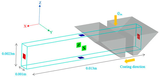
Figure 2.
Boundary conditions and computational domain for slot-die coating simulation: continuative (X), symmetry (Y), and velocity inlet/moving wall (Z).
3. Results
The coating characteristics of slot-die coating are critically dependent on coating parameters, particularly the coating speed (), volumetric flow rate () and coating gap (). To explore the process window for alumina slurry, preliminary simulations were conducted to assess the overall coating behavior as a function of speed while holding the flow rate constant. These simulations provide a basis for identifying flow regimes and critical speed thresholds beyond which defects such as dripping or air entrainment emerge. Rheological and interfacial properties of the alumina slurry were experimentally measured and implemented in the CFD simulations (Table 2). Viscosity was determined as the apparent viscosity measured at a representative shear rate of 31 s−1. The properties were applied in the VOF simulation framework via the Continuum Surface Force (CSF) method to accurately model the capillary force at the slurry–air interface [28]. The contact angles between the slurry and the two substrate types were also measured: 66.7° on glass and 137° on the dried alumina coating. The higher contact angle on the dried Al2O3 substrate (~137°) compared to glass (~66.7°) is attributed to the relatively hydrophobic nature of alumina surfaces and the additional contribution of surface porosity, which can further increase the apparent contact angle via air entrapment mechanisms [29].

Table 2.
Physical properties of the Al2O3 slurry used in simulation.
In this work, the slot-die coating process was categorized into three distinct flow regimes: overflow, stable, and unstable. These regimes were defined by the dynamic behavior of the upstream and downstream menisci and the presence or absence of entrapped air within the coating bead. The overflow regime occurs when the upstream meniscus climbs over the lip of the upstream die or when the downstream meniscus rises excessively along the downstream die surface. This condition typically results from an excessively high flow rate or an improperly set gap height, which causes the bead volume to exceed the geometrical capacity of the coating head. The stable regime represents the ideal coating condition. Here, the upstream meniscus remains stationary within the lip of the upstream die [20], and the downstream meniscus remains pinned near the edge of the downstream lip [30]. No air is entrained into the slurry, and the coating bead maintains a consistent geometry throughout the process. Under these conditions, uniform wet film thickness and well-dispersed particle distributions can be reliably achieved. The unstable regime is characterized by dynamic fluctuations in the meniscus position and curvature, especially near the upstream side. In this state, air is entrained into the coating bead, and the upstream meniscus may retreat toward or even beyond the slot gap, resulting in transient, unstable contact angles. This behavior can not only degrade the uniformity of film thickness but also significantly increase the likelihood of introducing defects such as voids and surface roughness. The classification into three regimes (overflow, stable, unstable) was based on clear experimental and simulation criteria, and further subdivision, while possible, was beyond the scope of this study.
3.1. Effect of Coating Gap
To investigate the effect of coating gap on coating stability, simulations were conducted under a fixed flow rate (0.7 mL/min) and coating speed (1.2 mm/s), while varying the coating gap from 200 µm to 400 µm. The resulting , pressure distribution, flow velocity, and shear rate are analyzed for coating stability and defect formation.
The velocity field (Figure 3a) demonstrates that narrower coating gaps reduce the fluid velocity near the upstream meniscus. At a 200 µm gap, the velocity magnitude approaches zero in the region adjacent to the upstream die lip, resulting in a stationary meniscus and minimizing dynamic contact angle fluctuations. In contrast, at 400 µm, higher velocities are observed at the same location, leading to meniscus displacement and unstable bead formation. This further supports the notion that smaller gaps promote flow stability by reducing viscous stresses on the free surface. Although a 400 µm gap was included in Figure 3a to illustrate the effect of large gap sizes on flow dynamics, it was excluded from further analysis due to consistently unstable meniscus behavior and impractical film thickness for multilayer ceramic AM. Thus, subsequent discussions focused on the more relevant 200–300 µm range.

Figure 3.
Simulation results for alumina slurry coating at various coating gaps under fixed flow rate (0.7 mL/min) and coating speed (1.2 mm/s): (a) velocity field; (b) pressure distribution; (c) velocity gradient.
The pressure profiles shown in Figure 3b reveal a pronounced pressure gradient beneath the downstream die lip in the 200 µm coating gap case, indicative of Poiseuille flow. As the gap increases, this gradient diminishes, indicating a transition to Couette-dominant flow at lower speeds. While this may enhance flow uniformity, it also reduces the stabilizing pressure acting on the bead, rendering the system more susceptible to air entrainment.
Figure 3c illustrates the velocity gradient within the coating bead for various coating gaps, which is proportional to the shear rate. As the coating gap decreases from 300 µm to 200 µm, the magnitude of the shear rate increases significantly, particularly near the upstream meniscus and downstream die lip. The 200 µm case exhibited a highly localized region of elevated shear near the upstream meniscus and the downstream die lip, unlike the broader stress distributions seen in the 250 µm and 300 µm cases. Excessively high shear stress and shear rates can promote aggregation among suspended particles, resulting in clustering and poor film homogeneity [31,32].
When the coating speed exceeds a critical threshold, the process becomes unstable due to the onset of air entrainment. This phenomenon, commonly referred to as dynamic wetting failure, occurs when the capillary pressure gradient—driven by the curvature of the liquid interface—fails to displace air sufficiently fast from the dynamic contact line. Once dynamic wetting failure occurs, maintaining a stable and uniform film becomes extremely difficult, leading to significant deterioration in coating quality [33]. The occurrence of dynamic wetting failure can be explained in terms of the capillary number (), defined as , where is the dynamic viscosity of the fluid, is the coating speed, and is the surface tension. The capillary number quantifies the relative importance of viscous forces to surface tension. As either viscosity or speed increases, so does the capillary number. Conversely, lowering enables the use of higher coating speeds while keeping within acceptable limits. The onset of dynamic wetting failure is typically observed when exceeds a critical capillary number, .
Figure 4a illustrates how the coating gap affects the stable coating window. As the coating gap decreases, the range of coating speeds that maintain a stable bead formation widens, suggesting enhanced process stability at smaller gaps. This is attributed to the suppression of fluid velocity near the upstream meniscus, which helps anchor the contact line and prevents meniscus instability. Figure 4b shows the dependence of the on the coating gap at different flow rates. For all tested conditions, increases as the coating gap decreases, indicating that the onset of dynamic wetting failure is delayed at narrower gaps. The curves shown in Figure 4b were based on CFD simulations under fixed parameters; experimental uncertainties were not considered in the model due to computational cost. The CFD-derived values were deterministic output for fixed coating speed, flow rate, coating gap, and material parameters. Consequently, replicate-based statistical errors were not shown. For each condition, was determined using a deterministic transition criterion. A single model evaluation per condition was used to identify the transition.
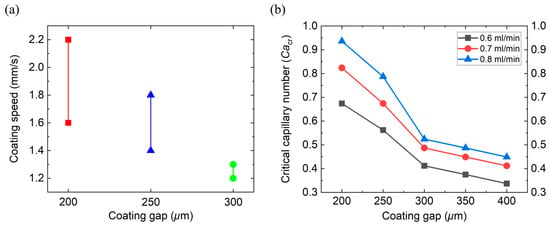
Figure 4.
(a) Stable coating speed window as a function of coating gap under a fixed flow rate (0.7 mL/min); (b) variation in critical capillary number with coating gap at different flow rates (0.6, 0.7, and 0.8 mL/min).
Taken together, these results highlight the critical role of the coating gap in determining the hydrodynamic stability and quality of the coated film. Narrower coating gaps were shown to suppress upstream flow velocity, enhance meniscus pinning through capillary forces, and raise the , thereby delaying the onset of dynamic wetting failure. Though narrow coating gaps favor coating stability, they can also impose a higher risk of defect formation due to high local shear. To prevent this, the coating speed and the flow rate must be carefully controlled to ensure that the induced shear stress remains below the aggregation threshold of the slurry system. Based on this analysis, a coating gap of 200 µm was selected as a representative condition for further investigation in the following sections.
3.2. Coating Behavior on Glass Substrate
To define the coating window and clarify the boundaries between operational regimes, the three coating regimes—stable, overflow, and unstable—were investigated with detailed numerical and experimental analyses. Each regime’s characteristics were analyzed in terms of pressure distribution, velocity field, shear stress, and air entrainment behavior, along with corresponding experimental validations.
3.2.1. Stable Regime
Figure 5 presents the numerical and experimental data under a stable coating condition ( = 1.8 mm/s, = 0.7 mL/min, = 200 µm). Figure 5a displays a bead morphology characteristic of stable flow, with the upstream meniscus pinned at the die lip and the downstream meniscus stabilized at the lip edge. No air entrainment was observed in the coating bead.
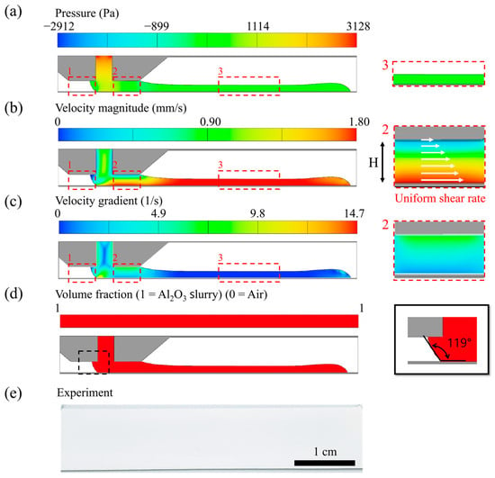
Figure 5.
Numerical and experimental results for the stable coating regime ( = 1.8 mm/s, = 0.7 mL/min, = 200 µm). (a) Pressure distribution, (b) velocity field, (c) velocity gradient, and (d) fluid fraction. (e) The experimental image shows a uniform coating without air entrainment.
In the upstream zone (Zone 1), the pressure gradient is nearly constant, and the velocity near the upper region of the upstream meniscus approaches 0 mm/s (Figure 5b). This velocity balance prevents dynamic wetting failure and ensures meniscus stability. The measured dynamic contact angle was approximately 119° (Figure 5d). In the downstream zone (Zone 2), both the pressure gradient and the velocity profile indicate Couette-dominant flow, as the velocity linearly increases toward the moving substrate. This uniform shear condition is conducive to homogeneous particle dispersion. Figure 5c reveals that the shear stress in this condition is about 600 Pa higher than at lower coating speeds, indicating that excessive velocity can promote particle aggregation. Finally, the film formation region (Zone 3) exhibits a plug-flow profile with negligible velocity or pressure gradients, confirming a stable transfer to the substrate. Figure 5e shows the experimental result, confirming the absence of air entrainment and demonstrating a continuous coating layer with uniform width.
3.2.2. Overflow Regime
Figure 6 illustrates the overflow condition ( = 0.7 mm/s, = 0.7 mL/min, = 200 µm), characterized by an excessive upstream meniscus that climbs beyond the die lip and a downstream meniscus that similarly surpasses the downstream die lip. This phenomenon is indicative of a flow rate significantly higher than the coating speed. In Zone 1, an appreciable pressure gradient and flow velocity (~0.5 mm/s) are observed, indicating strong upstream migration of Al2O3 slurry. Compared to the stable regime, this flow may increase the likelihood of particle accumulation near the die.
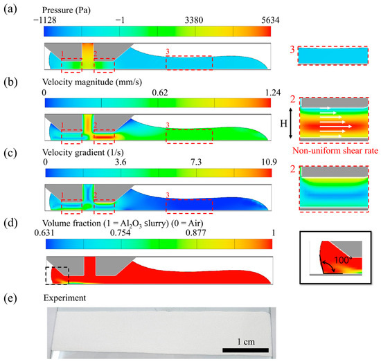
Figure 6.
Numerical and experimental results for the overflow coating regime ( = 0.7 mm/s, = 0.7 mL/min, = 200 µm). (a) pressure distribution; (b) velocity field; (c) velocity gradient; (d) fluid fraction; (e) experimental image shows film broadening.
Despite the relatively high flow rate, Figure 6d shows that air was entrained into the coating bead. The dynamic contact angle decreased to ~100°, and the meniscus oscillated while seeking equilibrium between flow rate and coating speed. During these transitions, transient air pockets were captured beneath the meniscus, leading to entrainment via dynamic wetting failure. In Zone 2, the pressure gradient (~2000 Pa) is significantly steeper than in the stable case. Figure 6b reveals a non-linear shear profile, with the maximum velocity occurring approximately 70–100 µm above the substrate, followed by a velocity decline near the die lip. This inhomogeneous shear rate can result in uneven particle dispersion and localized aggregation. The experimental observation (Figure 6e) shows that the coating width increases with time, confirming instability in film morphology and material deposition.
3.2.3. Unstable Regime
The unstable condition ( = 2.8 mm/s, = 0.7 mL/min, = 200 µm) is defined by an excessive coating speed, which forces the upstream meniscus beyond the slot gap and into the downstream die region. This displacement eliminates the circulation flow in Zone 1 observed in other regimes.
Figure 7a–d illustrate air entrainment through a curved upstream meniscus and rapidly fluctuating bead interface. The velocity field (Figure 7b) confirms a non-uniform velocity distribution with localized maxima (~2.80 mm/s), particularly near the upstream meniscus. Such non-linear profiles indicate heterogeneous shear stress, which can compromise particle distribution. Figure 7c shows that the shear stress under this regime peaks at 4437 Pa, the highest among all three conditions. In combination with the non-uniform flow, this level of stress significantly raises the risk of particle agglomeration and coating defects. Air entrainment is further detailed in Figure 7d, where a dynamic contact angle of ~142° leads to widespread air inclusion in the coating bead. Unlike the overflow condition, the unstable regime induces entrainment through both dynamic wetting failure and a capillary rupture mechanism.
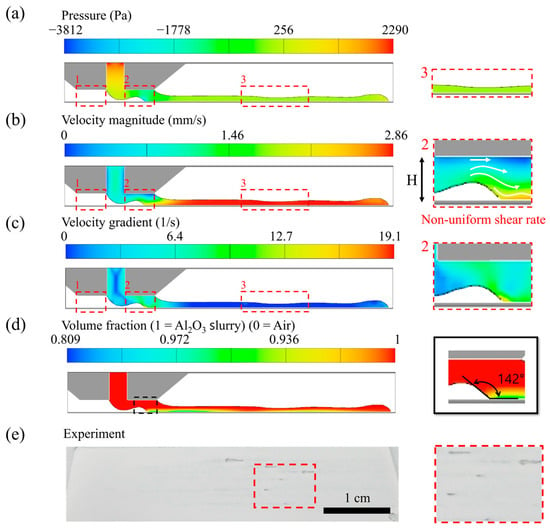
Figure 7.
Numerical and experimental results for the unstable coating regime ( = 2.8 mm/s, = 0.7 mL/min, = 200 µm). (a) pressure distribution, (b) velocity field; (c) velocity gradient; (d) fluid fraction; (e) experimental image confirms air entrainment and coating discontinuities.
To further clarify the air entrainment mechanism under unstable conditions, Figure 8 shows a time-resolved sequence of simulated volume fraction fields and dynamic contact angles. These snapshots reveal the evolution of the upstream meniscus and the recurring formation and rupture of the air entrainment over time. At t = 1.50 s (Figure 8a), the upstream meniscus shifts beyond the slot gap into the downstream die region, forming a steep interface with a dynamic contact angle of approximately 137°. This configuration facilitates initial air entrainment into the coating bead. By t = 1.55 s (Figure 8b), the meniscus deformation intensifies, creating a distinct capillary ridge near the upstream die lip, with a contact angle of ~140°.
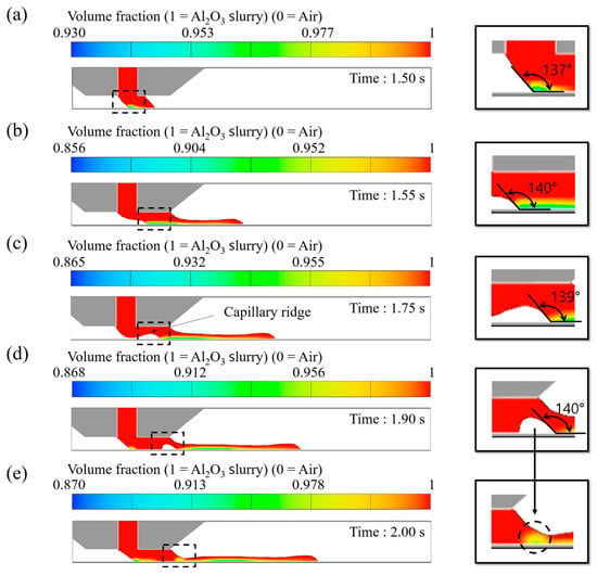
Figure 8.
Time-resolved simulation of volume fraction distribution (1 for alumina slurry and 0 for air) under unstable conditions ( = 2.8 mm/s, = 0.7 mL/min, = 200 µm), where (a) the upstream meniscus displacement beyond the slot gap with steep interface formation, (b) the development of a distinct capillary ridge near the upstream die lip, (c) partial blockage of the ridge by slurry flow leading to a void space, (d) the collapse of the void and rupture-driven air entrainment, and (e) the forward displacement of the meniscus initiating the next rupture cycle.
As time progresses to t = 1.75 s (Figure 8c), the slurry flow begins to block the left side of the capillary ridge, forming a void space within the coating bead. This void collapses at t = 1.90 s (Figure 8d), resulting in the rupture of the air entrainment being entrained into the bead. At t = 2.00 s (Figure 8e), the upstream meniscus resumes its forward displacement, initiating the next rupture cycle. These dynamics illustrate a periodic entrainment mechanism, driven by excessive coating speed and unbalanced flow rate, in which capillary ridge growth and collapse cause repeated coating discontinuity and air entrainment.
3.3. Coating Behavior on Dried Alumina Layer
As the coating proceeds layer-by-layer, all layers except for the first are deposited on top of previously dried alumina slurry films. Due to the high contact angle (~137°) between the slurry and the dried alumina substrate (Table 2), the wettability is significantly reduced compared to hydrophilic substrates such as glass. The hydrophobic nature of the dried alumina layer can reduce meniscus stability and lower the critical capillary number, thereby narrowing the stable coating window and increasing the likelihood of air entrainment and non-uniform film thickness in multilayer coating processes.
Figure 9 presents a comparison between simulation results (left) and experimental observations (right) for three representative coating conditions (overflow, stable, and unstable) performed on dried alumina slurry substrates. The simulations were carried out under fixed flow rate and coating gap ( = 0.7 mL/min, = 300 μm), while varying the coating speed. While a 200 µm coating gap was selected for the main analysis due to its relatively wide stable window and favorable shear stress profile, a 300 µm gap was additionally considered in Section 3.3 to explore how coating stability degrades near the upper bound of practical coating conditions. This allows for a broader assessment of gap-dependent flow behavior, particularly under challenging conditions such as dried alumina substrates. Compared to coatings on glass, all three conditions exhibit bulged bead formation and slurry accumulation near the upstream region when deposited on dried Al2O3 substrates. This behavior is attributed to the significant difference in wettability. As a result, slurry spreading is suppressed on the dried alumina surface, leading to the rounded meniscus shapes and higher fluid fraction in the central bead region, as observed in the simulation. The experimental observations were consistent with the simulation findings. Under unstable conditions, irregular coating patterns were observed, including uncoated regions and variations in film thickness. These non-uniformities are presumed to be influenced by the substrate’s altered surface characteristics after drying. The simulation results suggest that slurry spreading is hindered due to the low wettability of the dried alumina layer. In particular, the fluid accumulation observed near the upstream meniscus in simulations is consistent with the experimental evidence of localized slurry retention. These findings indicate that surface energy and absorption behavior of the dried layer can strongly influence the coating dynamics in multilayer processes.
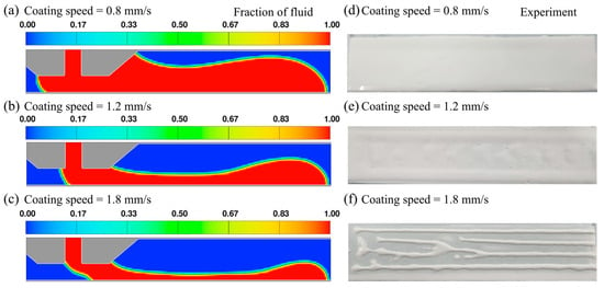
Figure 9.
Numerical and experimental results for three representative coating conditions on dried alumina slurry layer ( = 0.7 mL/min, = 300 μm). Simulation results showing fluid fraction fields at (a) = 0.8 mm/s, (b) = 1.2 mm/s, (c) = 1.8 mm/s, and corresponding experimental results at (d) = 0.8 mm/s, (e) = 1.2 mm/s, and (f) = 1.8 mm/s.
These results highlight a crucial aspect of multilayer coating in slurry-based ceramic additive manufacturing. While the dried ceramic layer serves as the substrate in all but the first layer, its wettability fundamentally alters the coating dynamics compared to non-porous substrates. Therefore, accurate prediction and control of slurry saturation behavior, particularly in relation to the drying degree and resulting pore size distribution, are essential to achieving consistent film thickness and interlayer adhesion. Furthermore, understanding the interplay between slurry properties and substrate surface energy will be critical in defining the coating window in slurry-based additive manufacturing.
Figure 10 shows stable coating windows constructed for three different gap heights ( = 200 µm, 250 µm, and 300 µm). As the coating gap increased, the range of stable coating speed narrowed significantly for a given flow rate. In particular, the 200 µm condition consistently exhibits the widest stable window across all tested flow rates, while the 300 µm condition is highly susceptible to instability, especially at lower flow rates. This observation aligns with earlier velocity field analysis, where narrower gaps suppressed upstream meniscus motion and promoted meniscus stability. These results confirm that precise gap control is crucial in multilayer ceramic AM, especially when dealing with hydrophobic dried alumina layers that amplify coating instabilities.
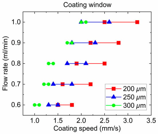
Figure 10.
Coating windows on dried alumina substrates at different coating gaps.
The present study examined a 50 wt% alumina slurry. Higher solid loadings (>60 wt%) are expected to result in increased viscosity and yield stress, which may lead to a reduced stable coating window and earlier formation of defects such as air entrainment and particle aggregation. Future studies should extend this analysis to more concentrated slurries to map out the coating window as a function of both solid content and rheological properties.
4. Conclusions
This study presented a combined numerical and experimental investigation of the slot-die coating process for ceramic slurries, with a focus on identifying the stable coating window applicable to additive manufacturing. The results highlight the following key findings:
- Three coating regimes (overflow, stable, and unstable) were mapped out over the investigated process window (coating speed 0.7–2.8 mm/s, flow rate 0.6–0.8 mL/min, coating gap 200–400 µm). Narrowing the coating gap markedly expanded the stable coating range: for example, at a 200 µm gap on a glass substrate, the process sustained a stable bead over the widest speed range without defects, whereas larger gaps led to a significantly narrower stable-speed window and earlier onset of coating instabilities.
- Volume-of-fluid simulations revealed that meniscus shape and shear stress distribution are highly sensitive to coating conditions. In unstable conditions with high coating speed or insufficient flow rate, the upstream meniscus became significantly distorted, and the peak shear stress reached ~4.4 kPa, which is the highest among all conditions, promoting air entrainment and particle agglomeration. In contrast, stable regime conditions maintained a pinned meniscus and moderate shear, preventing air entrainment and ensuring uniform slurry coating width.
- Coatings on the hydrophobic dried-alumina substrate (contact angle 137° vs. 66.7° on glass) exhibited far less wettability and more unsteady meniscus behavior than on glass. Consequently, the critical coating speed (or capillary number) for wetting failure was much lower on the dried layer, and the stable coating window contracted substantially. Experimentally, this was observed as frequent defects such as non-uniform coating width and air entrainment on dried alumina, whereas the glass substrate allowed a broader stable coating range. The experimental and simulation results were consistent with each other, confirming that reduced substrate wettability can directly lead to narrower operating windows and increased non-uniformity.
These findings of this work emphasize the importance of carefully controlling process parameters and substrate properties to enable reliable and uniform layer formation in multilayer ceramic additive manufacturing. The combined simulation and experimental approach presented here provides quantitative guidelines for optimizing the slot-die coating process. Future work will strengthen validation by quantitatively comparing simulations with available measurements and by incorporating statistical analyses to report uncertainty. It will also investigate how rheology and substrate wettability can be tuned to broaden the stable coating window and improve model fidelity, ultimately enhancing film quality in multilayer deposition.
Funding
This work was supported by the Ministry of Science and ICT (2024-22030005-20, RS-2023-00304763) and Commercialization Promotion Agency for R&D Outcomes (COMPA), Korea Evaluation Institute of Industrial Technology (00448195) grant funded by the Korea government (MOTIE), and Korea Institute of Industrial Technology (JA-25-0006).
Institutional Review Board Statement
Not applicable.
Informed Consent Statement
Not applicable.
Data Availability Statement
The raw CFD input decks and processed datasets used in this study cannot be shared externally due to project confidentiality and software licensing constraints. However, all information necessary to reproduce the simulations, including boundary conditions, geometry, material properties, mesh resolution, and solver settings, is fully described in the manuscript.
Conflicts of Interest
The author declares no conflicts of interest. The funders had no role in the design of the study; in the collection, analyses, or interpretation of data; in the writing of the manuscript; or in the decision to publish the results.
References
- Bharathi, V.; Anilchandra, A.; Sangam, S.S.; Shreyas, S.; Shankar, S.B. A review on the challenges in machining of ceramics. Mater. Today Proc. 2021, 46, 1451–1458. [Google Scholar] [CrossRef]
- Wang, J.-C.; Dommati, H.; Hsieh, S.-J. Review of additive manufacturing methods for high-performance ceramic materials. Int. J. Adv. Manuf. Technol. 2019, 103, 2627–2647. [Google Scholar] [CrossRef]
- Mühler, T.; Gomes, C.M.; Heinrich, J.; Günster, J. Slurry-based additive manufacturing of ceramics. Int. J. Appl. Ceram. Technol. 2015, 12, 18–25. [Google Scholar] [CrossRef]
- Truxova, V.; Safka, J.; Seidl, M.; Kovalenko, I.; Volesky, L.; Ackermann, M. Ceramic 3d printing: Comparison of sla and dlp technologies. MM Sci. J. 2020, 2020, 3905–3911. [Google Scholar] [CrossRef]
- Hur, H.; Park, Y.J.; Kim, D.-H.; Ko, J.W. Material extrusion for ceramic additive manufacturing with polymer-free ceramic precursor binder. Mater. Des. 2022, 221, 110930. [Google Scholar] [CrossRef]
- Chen, Z.; Sun, X.; Shang, Y.; Xiong, K.; Xu, Z.; Guo, R.; Cai, S.; Zheng, C. Dense ceramics with complex shape fabricated by 3d printing: A review. J. Adv. Ceram. 2021, 10, 195–218. [Google Scholar] [CrossRef]
- Sing, S.L.; Yeong, W.Y.; Wiria, F.E.; Tay, B.Y.; Zhao, Z.; Zhao, L.; Tian, Z.; Yang, S. Direct selective laser sintering and melting of ceramics: A review. Rapid Prototyp. J. 2017, 23, 611–623. [Google Scholar] [CrossRef]
- He, R.; Liu, W.; Wu, Z.; An, D.; Huang, M.; Wu, H.; Jiang, Q.; Ji, X.; Wu, S.; Xie, Z. Fabrication of complex-shaped zirconia ceramic parts via a dlp-stereolithography-based 3d printing method. Ceram. Int. 2018, 44, 3412–3416. [Google Scholar] [CrossRef]
- Hundley, J.M.; Eckel, Z.C.; Schueller, E.; Cante, K.; Biesboer, S.M.; Yahata, B.D.; Schaedler, T.A. Geometric characterization of additively manufactured polymer derived ceramics. Addit. Manuf. 2017, 18, 95–102. [Google Scholar] [CrossRef]
- Santoliquido, O.; Colombo, P.; Ortona, A. Additive manufacturing of ceramic components by digital light processing: A comparison between the “bottom-up” and the “top-down” approaches. J. Eur. Ceram. Soc. 2019, 39, 2140–2148. [Google Scholar] [CrossRef]
- Cima, M.; Oilveira, M.; Wang, H.; Sachs, E.; Holman, R. Slurry-based 3dp and fine ceramic components. In Proceedings of the Twelfth Solid Freeform Fabrication (SFF) Symposium, Austin, TX, USA, 6–8 August 2001; pp. 216–223. [Google Scholar]
- Grau, J.; Moon, J.; Uhland, S.; Cima, M.; Sachs, E. High green density ceramic components fabricated by the slurry-based 3dp process. In Proceedings of the Eighth Solid Freeform Fabrication (SFF) Symposium, Austin, TX, USA, 11–13 August 1997; pp. 371–378. [Google Scholar]
- Zocca, A.; Lima, P.; Günster, J. Lsd-based 3d printing of alumina ceramics. J. Ceram. Sci. Technol. 2017, 8, 141–148. [Google Scholar]
- Lima, P.; Zocca, A.; Acchar, W.; Günster, J. 3d printing of porcelain by layerwise slurry deposition. J. Eur. Ceram. Soc. 2018, 38, 3395–3400. [Google Scholar] [CrossRef]
- Ding, X.; Liu, J.; Harris, T.A. A review of the operating limits in slot die coating processes. AlChE J. 2016, 62, 2508–2524. [Google Scholar] [CrossRef]
- Li, Y.; Ma, L.e.; Yan, Y.; Wang, Q.; Zhang, P.; Liu, S.; Zhang, Y.; Yang, S. Thickness prediction of negative electrodes for lithium batteries in the slot-die coating process. Coatings 2025, 15, 206. [Google Scholar] [CrossRef]
- Fang, Z.; Wan, J.; Li, C.; Li, H.; Yan, Y. Contact-angle-guided semi-cured slot-die coating eliminates air entrapment in led multilayer films. Polymers 2025, 17, 1436. [Google Scholar] [CrossRef] [PubMed]
- Lin, C.F.; Wang, B.K.; Tiu, C.; Liu, T.J. On the pinning of downstream meniscus for slot die coating. Adv. Polym. Technol. 2013, 32, E249–E257. [Google Scholar] [CrossRef]
- Bhamidipati, K.L.; Didari, S.; Bedell, P.; Harris, T.A. Wetting phenomena during processing of high-viscosity shear-thinning fluid. J. Non-Newton. Fluid Mech. 2011, 166, 723–733. [Google Scholar] [CrossRef]
- Chang, H.M.; Chang, Y.R.; Lin, C.F.; Liu, T.J. Comparison of vertical and horizontal slot die coatings. Polym. Eng. Sci. 2007, 47, 1927–1936. [Google Scholar] [CrossRef]
- Crane, N.B. Impact of part thickness and drying conditions on saturation limits in binder jet additive manufacturing. Addit. Manuf. 2020, 33, 101127. [Google Scholar] [CrossRef]
- Pan, W.; Chen, Z.; Chen, X.; Wang, F.; Dai, G. Slot die coating window for a uniform fuel cell ink dispersion. AlChE J. 2022, 68, e17719. [Google Scholar] [CrossRef]
- Pan, S.; Wei, Y.; Chen, J.; Wu, C.; Jia, J. Simulation analysis of the start-up process of carreau-type fluid slot die coating. J. Coat. Technol. Res. 2024, 21, 1281–1289. [Google Scholar] [CrossRef]
- Malakhov, R.; Tjiptowidjojo, K.; Schunk, P.R. Mechanics of the low-flow limit in slot-die coating with no vacuum. AlChE J. 2019, 65, e16593. [Google Scholar] [CrossRef]
- Fang, Z.; Yan, Y.; Li, C.; Luo, X.; Zhou, P. Bubble defect generation mechanism in slot die coating of high-viscosity fluids. ACS Appl. Mater. Interfaces 2024, 16, 11890–11900. [Google Scholar] [CrossRef]
- Moukalled, F.; Mangani, L.; Darwish, M. The finite volume method. In The Finite Volume Method in Computational Fluid Dynamics: An Advanced Introduction with Openfoam® and Matlab; Springer: Berlin/Heidelberg, Germany, 2015; pp. 103–135. [Google Scholar]
- Hirt, C.W.; Nichols, B.D. Volume of fluid (VOF) method for the dynamics of free boundaries. J. Comput. Phys. 1981, 39, 201–225. [Google Scholar] [CrossRef]
- Brackbill, J.U.; Kothe, D.B.; Zemach, C. A continuum method for modeling surface tension. J. Comput. Phys. 1992, 100, 335–354. [Google Scholar] [CrossRef]
- Redón, R.; Vazquez-Olmos, A.; Mata-Zamora, M.; Ordonez-Medrano, A.; Rivera-Torres, F.; Saniger, J. Contact angle studies on anodic porous alumina. Rev. Adv. Mater. Sci. 2006, 11, 79–87. [Google Scholar] [CrossRef]
- Chang, Y.-R.; Chang, H.-M.; Lin, C.-F.; Liu, T.-J.; Wu, P.-Y. Three minimum wet thickness regions of slot die coating. J. Colloid Interface Sci. 2007, 308, 222–230. [Google Scholar] [CrossRef]
- Litchy, M.R.; Grant, D.C.; Schoeb, R. Effects of shear and cavitation on particle agglomeration during handling of cmp slurries containing silica, alumina, and ceria particles. In Proceedings of the 12th International CMP-MIC Conference, Fremont, CA, USA, 6–8 March 2007; pp. 366–375. [Google Scholar]
- Khanna, A.J.; Gupta, S.; Kumar, P.; Chang, F.-C.; Singh, R.K. Study of agglomeration behavior of chemical mechanical polishing slurry under controlled shear environments. ECS J. Solid State Sci. Technol. 2018, 7, P238. [Google Scholar] [CrossRef]
- Vandre, E.; Carvalho, M.S.; Kumar, S. Delaying the onset of dynamic wetting failure through meniscus confinement. J. Fluid Mech. 2012, 707, 496–520. [Google Scholar] [CrossRef]
Disclaimer/Publisher’s Note: The statements, opinions and data contained in all publications are solely those of the individual author(s) and contributor(s) and not of MDPI and/or the editor(s). MDPI and/or the editor(s) disclaim responsibility for any injury to people or property resulting from any ideas, methods, instructions or products referred to in the content. |
© 2025 by the author. Licensee MDPI, Basel, Switzerland. This article is an open access article distributed under the terms and conditions of the Creative Commons Attribution (CC BY) license (https://creativecommons.org/licenses/by/4.0/).