1. Introduction
M50 steel and its variant M50NiL steel, known as second-generation bearing steels, are widely used in aviation bearings due to their excellent dimensional stability, thermal hardness, and contact fatigue resistance [
1,
2]. With the continuous increase in the operating speed of modern aviation engine transmissions, bearing rotational speeds have also risen significantly. In high-speed metal friction pairs, the degradation of liquid lubrication can lead to elevated raceway temperatures, resulting in thinner or even ruptured oil films. Surface adhesive failure has thus become a critical damage mode in bearing steels [
3]. High-temperature solid self-lubricating materials offer a promising solution to overcome the limitations of liquid lubrication and are among the most effective strategies for addressing friction and wear issues in high-temperature environments. Diamond-like carbon (DLC) films, as solid lubricants, have attracted considerable research interest due to their high hardness and modulus, excellent tribological properties, chemical inertness, and relatively low cost [
4]. The performance of DLC coatings is primarily determined by the overall microstructure and the sp
3 bond content [
5]. Low-hardness and sp
2-rich DLC coatings may exhibit significant wear due to structural transformations, such as graphitization [
6]. Hainsworth and Uhure compared the properties of different DLCs and found that the hard amorphous carbon variants can have a range of hardness values from 10 to 20 GPa [
7]. YANG et al. reviewed the tribological characteristics of these amorphous carbon films and found that the friction coefficient of these amorphous carbon films is lower than 0.2 when at room temperature in air [
8]. The adhesion of DLC films is another critical factor in enhancing their future applicability. There are performance differences between the carbon film with high hardness and a soft steel base, such as the hardness, thermal expansion coefficient (α
C ≈ 0.8–2 × 10
−6 K
−1, α
Fe ≈ 11.8 × 10
−6 K
−1), and deformation capabilities [
9]. The higher the hardness of the carbide film, the greater the residual stress it exhibits, and consequently, the weaker the adhesion between the film and the substrate, which may lead to the delamination of the high-hardness film from the soft steel substrate—a phenomenon commonly referred to as the “egg-shell effect” [
10,
11]
The incorporation of an intermediate layer has been demonstrated to be an effective strategy for mitigating residual stress [
12]. Sun et al. improved the adhesion of DLC coatings to steel substrates from 9.0 N to 13.8 N through the introduction of a WC intermediate layer [
10]. The limited thickness of such coatings with an intermediate layer restricts their load-bearing capacity, making them unsuitable for demanding aviation-bearing applications. In our previous work [
13], a novel self-lubricating layer reaching hundreds of micrometers was fabricated on M50NiL steel through a plasma-assisted thermochemical treatment. The DLC structure is anchored in the pre-nitrided layer by carbide/nitride. This approach significantly improves both the load-bearing capacity and tribological performance, showing great potential for practical applications. The diffusion coefficient of carbon atoms is determined by the carburizing temperature—the higher the temperature, the faster the carbon diffuses [
14]. Moreover, the particle size, crystallinity, and sp
2 content of carbon-rich films exhibit high thermal sensitivity [
15]. The effects of the plasma-carburizing temperature on the microstructure and performance of this integrated functional layer remain unclear. Therefore, a comprehensive investigation into the influence of temperature on the structural evolution and mechanical behavior of the functional layer is of crucial importance.
Therefore, to enable the precise design and control of wear-resistant and friction-reducing functional layers, it is imperative to systematically investigate microstructural evolution at various plasma-carburizing temperatures based on experimental observations. In this study, pre-nitrided M50 steel was treated using plasma carburizing within a temperature range of 410 to 570 °C, which includes its conventional nitriding temperature. The resulting microstructure was thoroughly characterized using optical spectroscopy, scanning electron microscopy equipped with an energy-dispersive spectrometer (SEM-EDS), transmission electron microscopy (TEM), X-ray diffraction (XRD), and electron probe microanalysis (EPMA). The microhardness and wear resistance of the modified layer were evaluated through Vickers hardness testing and pin-on-disc tribological experiments. Based on these findings, the influence of the plasma-carburizing temperature on the microstructure, phase composition, and mechanical properties of the functional layer was comprehensively analyzed. The phase transformation behavior under different temperature conditions was elucidated, providing a fundamental basis for the industrial application of this technology in aviation bearings.
2. Experiment
The experimental material was quenched M50 steel, with the steel size being a cylindrical shape of Φ130 mm. The samples were processed into 12 mm × 12 mm × 5 mm blocks by wire cutting. The nominal chemical composition of the M50 steel was Fe-0.85C-1V-4Mo-4Cr (in wt.%). Based on previous research [
16], the nano-nitrided layer of M50 steel obtained through nitriding treatment at 530 °C, which is the temperature for its secondary hardening, exhibits the best performance. In this paper, this nitrided layer is used as the initial microstructure for subsequent plasma carburizing treatment. The M50 samples were plasma-nitrided at the secondary hardening temperature of 530 °C for 6 h under a gas flow ratio of 100 mL/min N
2 and 300 mL/min H
2. The pre-nitriding treatment was conducted using a pulsed direct current (DC) voltage (U = 660 V) and furnace pressure (P = 250 Pa). The nitrided samples were designated as “N”. Before plasma carburizing, the sample was ultrasonically cleaned in acetone for 5 min to remove surface oil stains. Then, it was dried with a hair dryer and suspended in the self-developed plasma-carburizing furnace. The schematic diagram and parameters of the plasma carburizing furnace are shown in
Figure S1 and Table S1, respectively. The plasma-carburizing treatments were carried out at different temperatures from 410 °C to 530 °C, with a gas flow ratio of 80 mL/min CH
4, 50 mL/min Ar, and 350 mL/min H
2 for 4 h. The carburized samples were designated as “N-C410 °C to N-C570 °C”, as listed in
Table 1.
To examine the cross-sectional microstructure of the composite layer, the samples were sectioned along the direction perpendicular to the surface, ground using 240–2000 grit SiC sandpapers, polished with diamond polishing agent, and etched in a solution consisting of 96% C2H5OH and 4% HNO3. Optical microscopy (OLYMPUS-GX51, Tokyo, Japan) and scanning electron microscopy (SEM) equipped with energy-dispersive X-ray spectroscopy (EDS) (AGSUPRA55, Carl Zeiss, Jena, Germany) were employed to analyze the microstructure of both the surface and cross-section of the modified layer. The surface phase structure was characterized by X-ray diffraction XRD (Bragg-Brentano θ-2θ geometry) using Cu-K radiation and grazing incidence X-ray diffraction at a 2° incidence angle (Empyrean, PANalytical B.V., Philips., Almelo, The Netherlands). An Invia-Reflex Raman microscope (Renishaw, Wotton-under-Edge, UK) and X-ray photoelectron spectroscopy (XPS, Escalab 250Xi, ThermoFisher, Waltham, MA, USA) were applied to analyze the chemical structure and electronic status evolution of the film. Transmission electron microscopy operating at 300 kV (Tecnai F30 G2, FEI, Hillsboro, OR, USA) was conducted to determine the microstructural and crystallographic features of the film. For the TEM sample preparation, the surface was protected with tape during grinding and ion thinning from the substrate side with ion-thinning equipment (GATAN695).
Microhardness tests were conducted on both the surface and cross-section using a Vickers hardness tester (HV-1000, Shanghai Zhongyan Industrial Co., Ltd., Shanghai, China) under a load of 200 g, with an indentation dwell time of 15 s per measurement. A nano-indenter XP (MTS NANO INDENTER XP) was used to measure the surface hardness with the indentation depths of 100 nm and 1000 nm. The average value was obtained from three independent tests conducted under identical conditions to ensure the reliability of both the hardness profile and the wear resistance performance. The wear resistance was evaluated based on the wear rate and friction coefficient, which were measured using a pin-on-disk tribometer (Type POD-I, HIT, Harbin, China) equipped with a 5 mm diameter WC ball at an ambient temperature and in air. During the test, the sample rotated at a speed of 200 r/min for 1800 s under a contact load of 10 N, while the WC ball remained stationary. A laser confocal microscope (OLS-3000, Olympus, Tokyo, Japan) was used to calculate the volume wear rate by Equation (1), based on the wear tracks dimensional.
where
η is the volume wear rate (in mm
3·N
−1·m
−1), Δ
V is the wear volume (in mm
3) calculated by three-dimensional wear tracks,
F is the load (in N), and
L is the total taxiing distance (in m).
3. Results and Discussion
For a comparative analysis, the surface morphologies of the pre-nitrided and carburized samples are illustrated in
Figure 1. As shown in
Figure 1a, the surface morphology of the pre-nitrided sample exhibits a dense crumb-like microstructure, which is consistent with the descriptions reported in the literature [
16]. The original nitride clusters are dissociated under plasma bombardment during and following carburizing, resulting in the formation of a film-like structure accompanied by numerous fine carbide particles. Nitride clusters may be etched by chemically enhanced desorption processes at conditions where the ion energy is below the physical sputtering threshold [
17]. The decomposition of nitrides leads to a comparatively porous surface at the relatively low carburizing temperature of 410 °C in
Figure 1b. With an increase in the carburizing temperature, a continuous and compact film-like structure forms on the surface, while the size of the formed carbide particles increases slightly, as illustrated in
Figure 1c. When the carburizing temperature reaches 570 °C, carbide coarsening occurs, leading to the disruption of the originally dense film-like structure, as depicted in
Figure 1d. Therefore, the surface roughness first decreases and then increases with the rise in temperature. The sample N-C 490 °C has the minimum roughness of Ra 12.2 nm (
Figure S2).
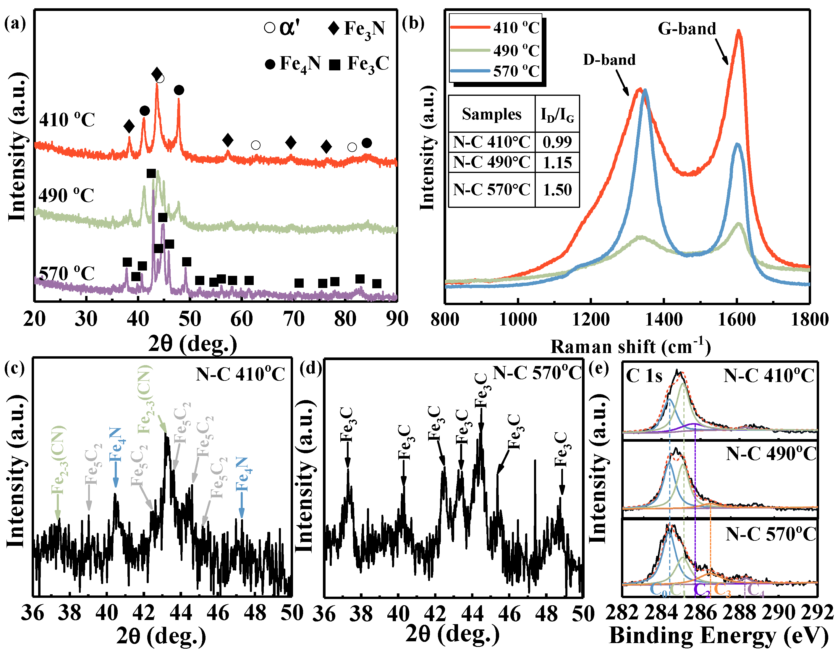
Figure 2a presents the phase composition of the surface of pre-nitrided M50 steel following plasma carburizing at temperatures ranging from 410 to 570 °C, aiming to elucidate the influence of the carburizing temperature on the phase structure of the functional surface layer. At relatively low carburizing temperatures of 410 °C, XRD analysis reveals that the surface remains predominantly composed of the nitrides Fe
3N and Fe
4N, along with a minor amount of the matrix phase α’, indirectly indicating the nitride clusters’ desorption. With the increasing carburizing temperature, the diffraction peaks corresponding to the nitrides, particularly Fe
4N, are progressively replaced by those of the carbide Fe
3C. This transition can be attributed to the lower thermodynamic stability of Fe
4N compared to Fe
2~3N phases under high-carbon conditions [
18]. Upon reaching a carburizing temperature of 570 °C, only the Fe
3C carbide phase is detected on the surface of the functional layer. Due to the limited penetration depth of X-rays (~1.4 μm), the phase structure of the film has been further clarified by a grazing incidence XRD and the results are depicted in
Figure 2c,d. The additional diffraction patterns observed in
Figure 2c are attributable to the carbide phase Fe
5C
2, whereas all the diffraction patterns presented in
Figure 2d have been unambiguously indexed to the carbide Fe
3C. The results indicate that the modified layer exhibits a gradient phase structure, transitioning from Fe
5C
2, Fe
2~3 (CN), and a small amount of Fe
4N to the nitrides Fe
3N and Fe
4N along the depth direction, particularly under lower carburizing temperatures.
Raman spectroscopy was employed to further investigate the bonding configuration of the surface after carburizing, as shown in
Figure 2b. The Raman spectra exhibit similar profiles, featuring two distinct peaks at approximately 1340 cm
−1 and 1600 cm
−1, which correspond to the D band and G band, respectively. These Raman spectra are characteristic of amorphous carbon structures [
19]. Both the D and G bands are associated with sp
2-hybridized carbon configurations. The D band reflects the structural disorder and defect density within the lattice, whereas the G band originates from the stretching vibrations of the sp
2-bonded carbon pair [
20].The intensity ratio of the D peak and G peak in amorphous carbon-rich structures can qualitatively reflect the content of sp
3 bonds in the film structure. As the temperature increases, I
D/I
G increases from 0.99 to 1.50, indicating that the content of sp
3 bonds decreases in the amorphous carbon layer.
Figure 2e shows the X-ray photoelectron spectroscopy from C1s exhibiting five Gaussian peaks, C
0–C
4, located at 284.4 eV, 285.1 eV, 285.5 eV, 286.5 eV, and 288.3 eV, respectively. C
0 corresponds to sp
2 C–C bonds, as in graphite, while C
1 represents sp
3 C–C bonds, as in diamond. C
2 and C
3 are attributed to sp
3-hybridized and sp
2-hybridized carbon atoms bonded to nitrogen derived from the nitride [
20,
21,
22]. The C
4 peak is associated with the C–O bond, where oxygen primarily originates from the sample preparation process. Generally, the proportion of chemical bonds within the carbon layer can be evaluated based on the relative area of the corresponding peak. The area share is shown in
Table 2. It can be observed that when the carburizing temperature is below 490 °C, the area share of C
1 (sp
3 bond) is higher than that of C
0 (sp
2 bond), indicating that the film structure is more likely to exhibit a diamond-like character, which contributes to the enhanced hardness. When the temperature reaches 570 °C, the area share of C
0 exceeds 50% and the film exhibits graphite-like characteristics, consistent with the analysis of the Raman.
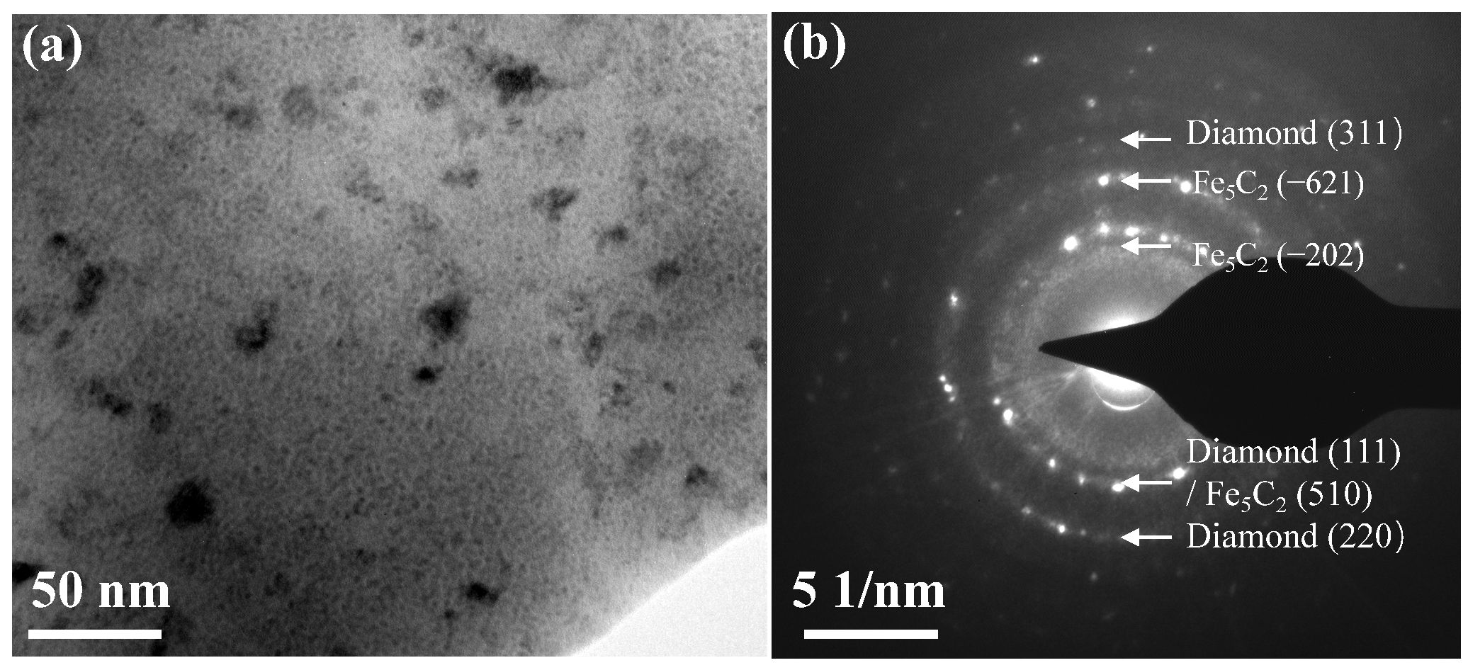
To further elucidate the structural characteristics of the surface carbon-rich layer, TEM images of the carburized surface of sample N-C490 °C are presented in
Figure 3a. The bright-field image reveals that the carbon-rich structure consists of an amorphous matrix incorporating embedded nanoparticles, consistent with the results of the Raman analysis. The selected area electron diffraction (SAED) patterns of nanoparticles observed in
Figure 3b is indexed as Fe
5C
2 and a diamond, which indicates the formation of diamond-like structure [
23]. This indirectly confirms the mechanism of the diamond-like carbon formation described in the literature [
13]. A surface with a high C/N ratio is conducive to the formation of high-carbon compounds such as Fe
5C
2 at a low temperature (≤490 °C), and Fe
5C
2 is more favorable than Fe
3C for the formation of a carbon-rich structure with a higher sp
3 bond content.
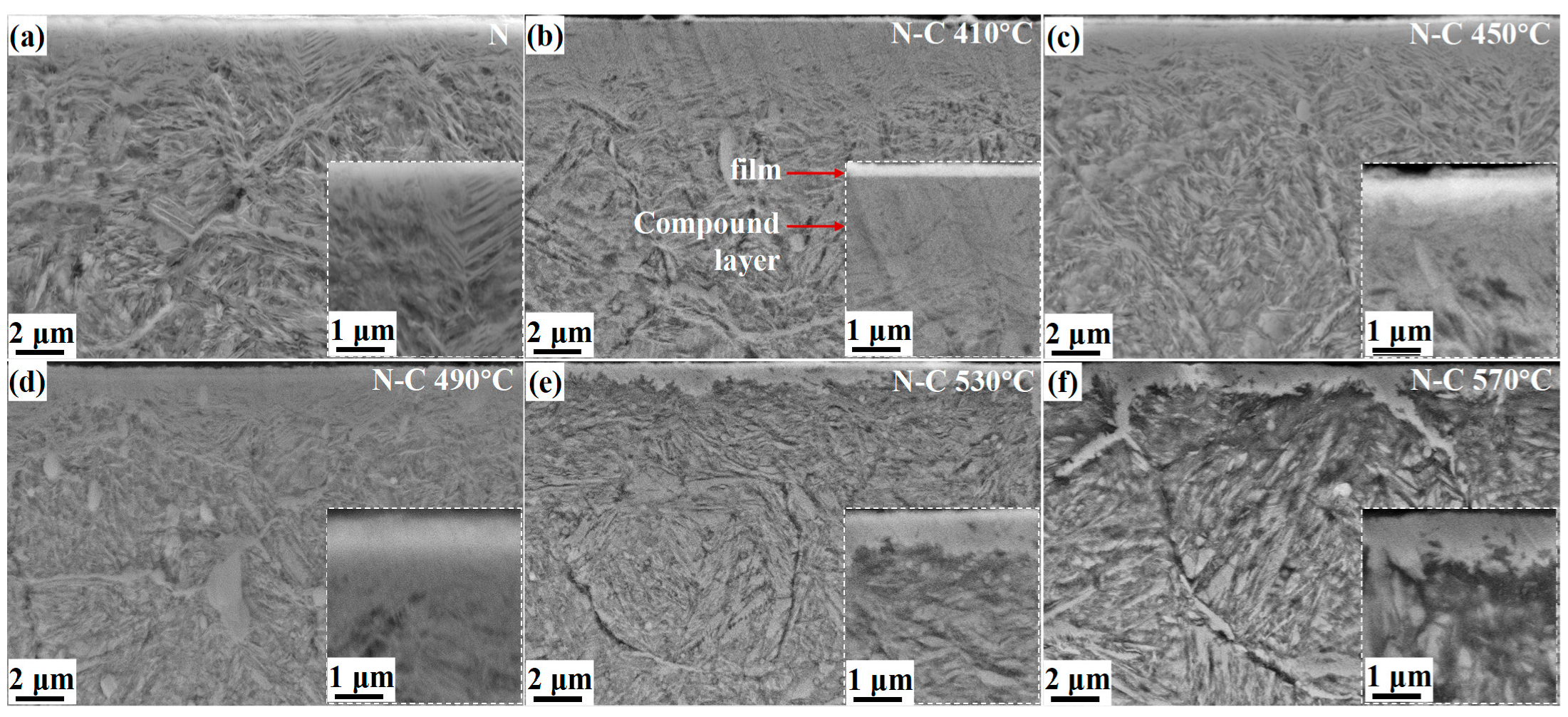
The cross-sectional microstructure of carburized samples is illustrated in
Figure 4, whereas the cross-sectional microstructure of the pre-nitrided sample is also displayed for comparative purposes. The high affinity between alloying elements such as Cr, Mo, and V in the modified layer and C and N atoms promotes the formation of carbon–nitrogen compounds, where the modified layer close to the surface was etched dark brown by nitric acid alcohol [
16]. The modified layer of sample N consists solely of a diffusion layer. A white bright layer is added to the diffusion layer after carburizing in
Figure 4b–f. The thickness of the modified layer increases monotonously from 106 μm to 148 μm as a function of the carburizing temperature. Since both N and C atoms preferentially occupy octahedral interstitial sites in martensite, the pre-implanted N atoms will hinder the entry of surface C atoms, resulting in the formation of carbides during carburizing. According to reference [
13], at a temperature of 500 °C, the diffusion coefficient of carbon in cementite is approximately 10
−19 to 10
−20 m
2/s, which is much lower than that in ferrite, ranging from 10
−12 to 10
−13 m
2/s. The compound layer will act as a barrier to the diffusion of carbon atoms. Thus, the thickness enhancement of the modified layer depends on the N atom diffusion not the C atom, although the diffusion coefficients of carbon and nitrogen atoms in the matrix are of the same order of magnitude [
24]. The illustration in
Figure 4f shows that after carburizing at a high temperature of 570 °C, a lamellar structure emerged in the original nitrided layer. It is speculated that this might be due to the reduction in nitrogen atoms on the surface as the temperature rises, allowing carbon atoms to diffuse towards the core and inducing the formation of the lamellar structure [
16].
To investigate the evolution of the white bright layer during carburizing at varying temperatures, the cross-section of the carburized sample was observed by SEM, as shown in
Figure 5. The pre-nitrided layer comprises an ultra-thin compound layer and an underlying diffusion layer exhibiting a needle-like morphology in
Figure 5a. The cross-sectional microstructures of the functional layers after carburizing are depicted in
Figure 5b–f. Unlike the compound layer formed after traditional carburizing, the white bright layer consists of a DLC film and a compound layer, while the diffusion layer remains with a needle-like morphology. The DLC film exhibits a clear interface with the compound layer of the sample carburized at 410 °C, which is not conducive to the improvement of the adhesion between the membrane and the substrate. The interface gradually disappears with the increasing temperature, leading to the formation of a homogeneous surface layer. This phenomenon may be attributed to the diffusion of nitrogen atoms into the deeper regions of the diffusion layer as the temperature increases, leading to a reduction in the surface nitrogen content. Consequently, carbides progressively replace the initial nitrides, and the original interface is gradually eliminated with the continuous formation of carbides.
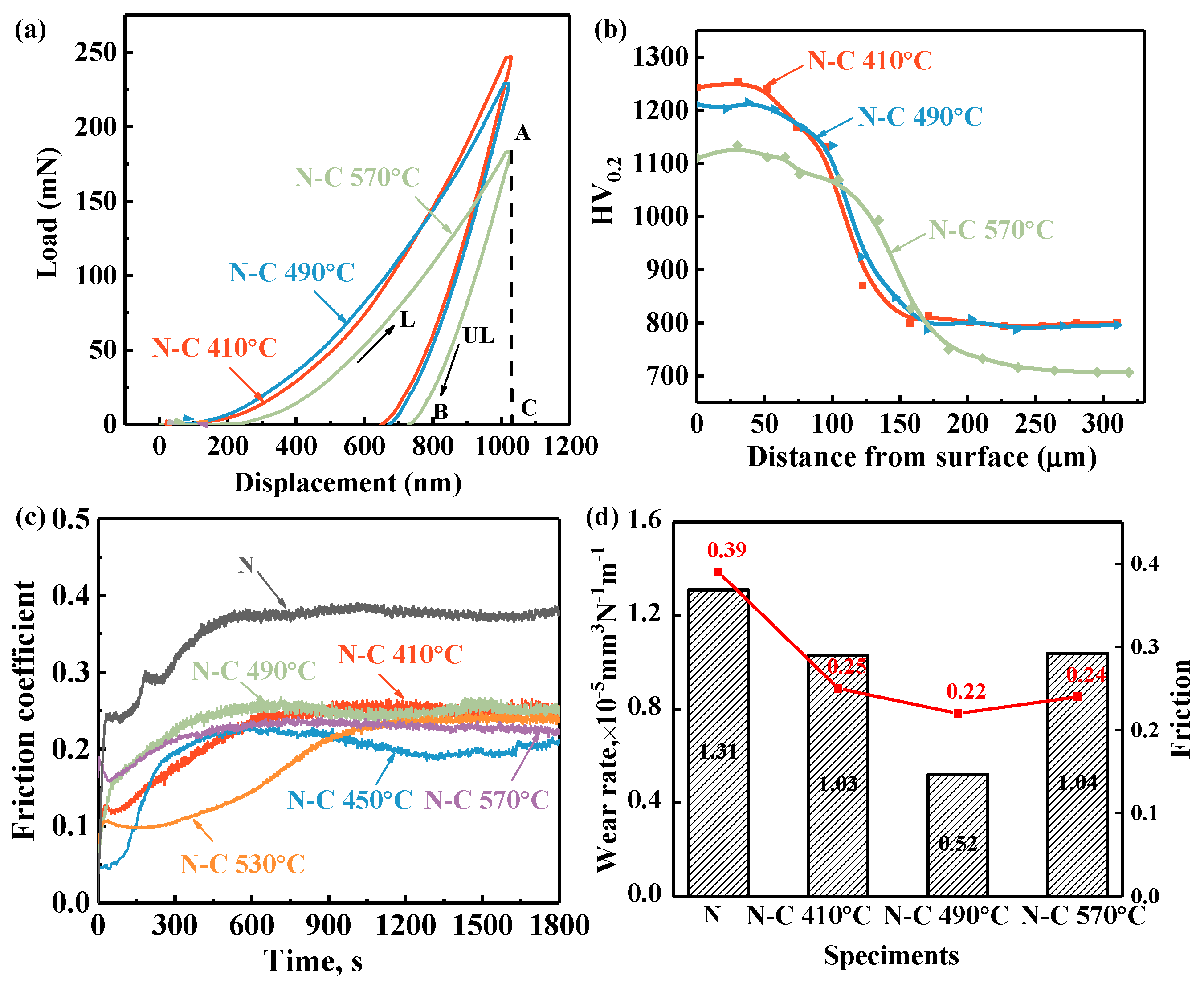
The load–depth curves for carburized samples are inserted in
Figure 6a, where L and UL represent the loading and unloading curves. The results are shown in
Table 3. The surface’s hardness decreases from 13.42 GPa to 9.93 GPa with the carburizing temperature increasing from 410 °C to 570 °C, implying a reduction in the sp
3 bonds of the carbon-rich structure. H/E, used to evaluate the wear resistance, enhances to a peak of 0.58 when the temperature arrives at 490 °C, corresponding to excellent wear resistance [
25]. The decrease in the friction coefficient after plasma carburizing is primarily attributed to the formation of a functional layer in
Figure 6c. The plasticity factor η
p, calculated as the ratio of the plastic deformation work (W
p) to total deformation work (W
t), is employed to assess the plasticity of the samples. A higher η
p value indicates superior plasticity with the temperature rising. Due to the thickness of the DLC film being too thin, an indentation depth of 100 nm was employed to evaluate the DLC film to reduce the influence of the substrate. The hardness of the surface of sample N-C 490 °C decreases from 19.73 GPa to 12.02 GPa as the penetration depth increases from 100 nm to 1000 nm, indicating that the DLC film exhibits higher hardness compared to the subsurface region.
Figure 6b shows the influence of the carburizing temperature on the microhardness distribution of the wear-resistant and friction-reducing functional layer. The hardness–depth profile of sample N-C410 °C gradually decreases from the surface 1280 HV0.2 to the core 785 HV0.2. The formation of a gradual hardness–depth profile contributes to enhancing the interfacial adhesion between the high-hardness film and the substrate, thereby effectively mitigating the risk of the “egg-shell” effect. As the carburizing temperature increases from 410 °C to 570 °C, the surface hardness gradually decreases from 1280 HV
0.2 to 1100 HV
0.2. The effective hardening depth is defined as the depth at which the hardness exceeds the core hardness by 50 HV
0.2. According to the cross-sectional microstructure analysis of the modified layer shown in
Figure 5, the increase in the thickness of the hardened layer during the plasma carburizing process is primarily attributed to the redistribution of nitrogen atoms in the pre-nitrided layer. As the temperature increases, the diffusion coefficient of the nitrogen atoms also increases, resulting in more pronounced thickening. For M50 steel, the core hardness is primarily attributed to the precipitation strengthening effect of carbides. When the carburizing temperature exceeds the secondary hardening temperature, carbide coarsening occurs, leading to a significant reduction in the core hardness. Therefore, performing carburizing at a temperature below the nitriding temperature (530 °C) is beneficial for maintaining the excellent properties of the original nitrided layer.
Figure 6c illustrates the variation in the surface friction coefficient of the dual-permeation sample as a function of the sliding time. For comparison, the friction coefficient of the nitrided sample N is also presented. During the running-in period, the friction coefficient curve of sample N exhibits significant fluctuations, which result from debris generated during the wear process. Subsequently, the system transitions into a stable stage, where the friction coefficient gradually stabilizes around 0.39. It is generally accepted that increasing the surface hardness can mitigate such debris-induced fluctuations. The carburized samples exhibits minimal fluctuations during the running-in phase, demonstrating a much smoother behavior compared to the quenched sample. Furthermore, in the stable stage, the friction coefficient ranges from 0.2 to 0.25 [
26], representing a reduction of approximately 35% relative to the sample N. According to the literature [
27], the anti-friction properties of amorphous carbon films, such as diamond-like carbon, are mainly due to the increase in sp
2 bonding under shear stress, a phenomenon commonly referred to as graphitization transformation.
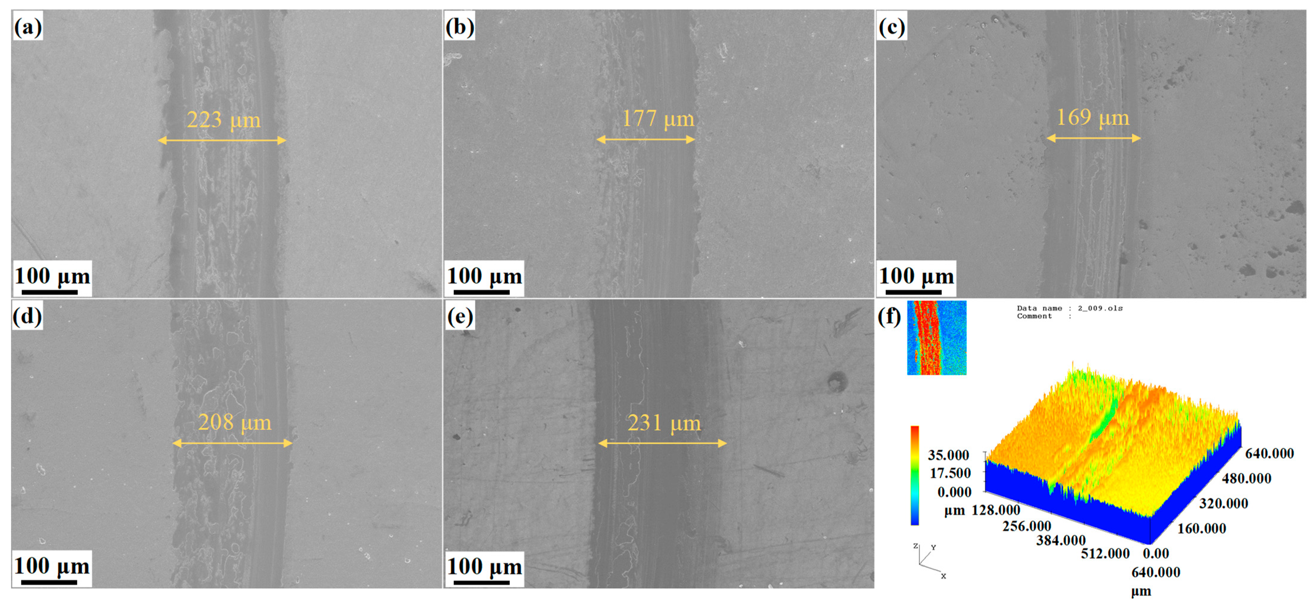
The volume wear rate was calculated according to the three-dimensional profile of the wear scars shown in
Figure 7f. As illustrated in
Figure 6d, the volume wear rates of the samples subjected to carburizing at various temperatures, measured after 1800 s of sliding under a load of 10 N, range from 0.52 to 1.04 × 10
−5 mm
3·N
−1·m
−1. The wear rate is markedly reduced after carburizing, amounting to less than 40% of that observed for the nitirided sample. As the carburizing temperature increases from 410 °C to 570 °C, the wear amount initially decreases and subsequently increases, resulting in the lowest wear rate observed for the carburized sample N-C 490 °C. This phenomenon can be attributed to the carbon-rich surface structure of sample N-C 490 °C, which exhibits a high content of sp
3 bonds—characteristic of diamond-like carbon (DLC) films known for their high hardness and excellent wear resistance. Furthermore, the functional layer formed at 490 °C features an integrated microstructure, thereby enhancing the adhesion of the high-hardness film.
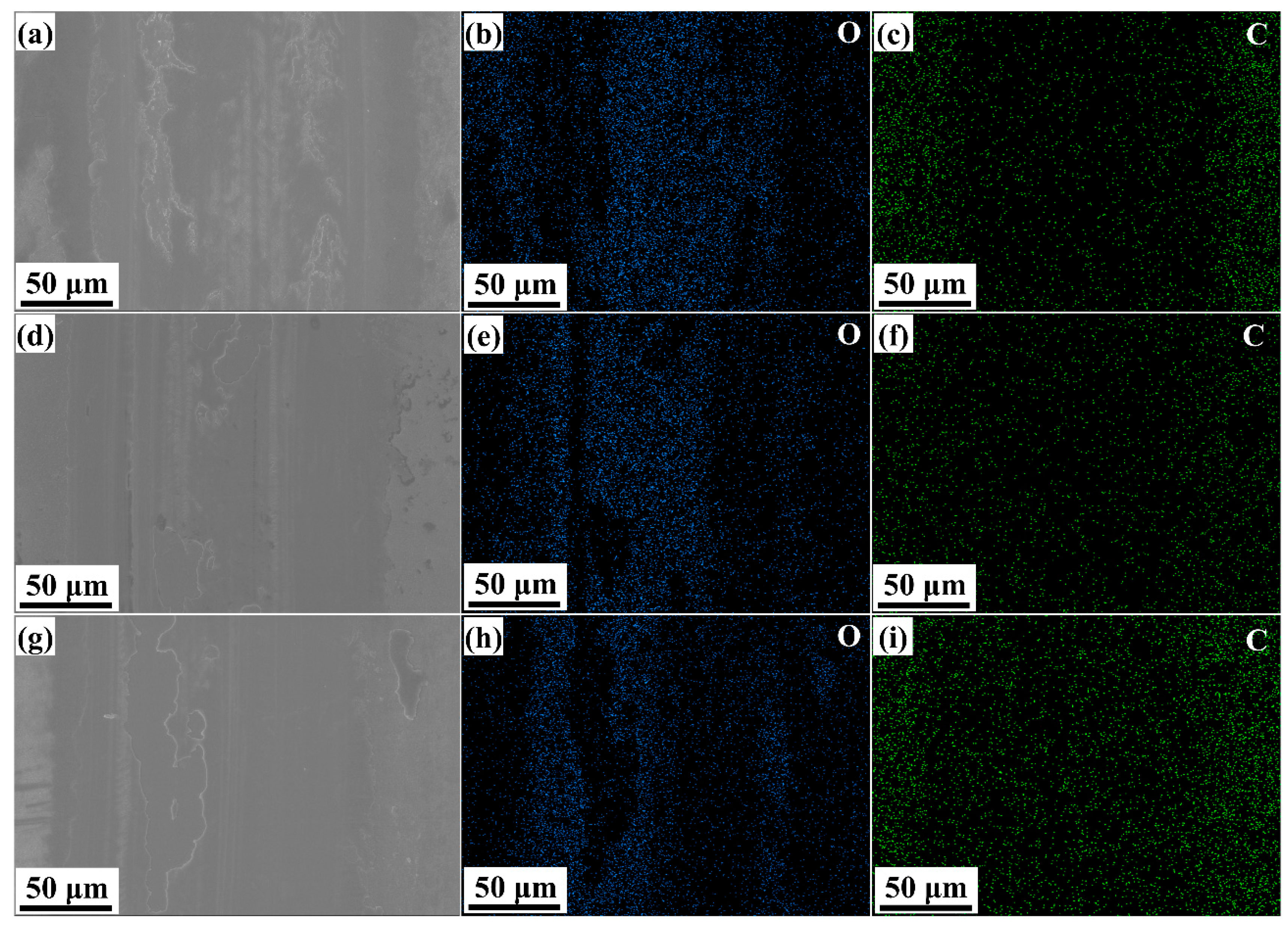
Scanning electron microscopy (SEM) was employed to examine the surface wear scar morphologies of the carburizing samples, while energy-dispersive X-ray spectroscopy (EDS) was utilized for the compositional analysis, as presented in
Figure 7 and
Figure 8. As observed in
Figure 7a–e, the width of the wear scar initially decreases and subsequently increases with the rising temperature; the narrowest wear scars also belong to carburizing sample N-C490 °C, consistent with the wear rate. The functional layer containing a DLC structure has the effect of wear resistance and friction reduction due to graphitization [
28]. Furthermore, minor spalling and smearing features are observed in the wear scars of carburized samples, indicating the presence of mild adhesive wear.
Figure 7f shows the three-dimensional profile of wear scars for the carburized sample. A limited number of shallow grooves are present which are characteristic of mild abrasive wear [
28].
As shown in the magnified view of the wear scar in
Figure 8, there is a small amount of spalling present in the wear marks, which indicates the occurrence of very slight adhesive wear. The energy-dispersive X-ray spectroscopy (EDS) analysis of the wear scar reveals a significant oxygen content, indicating that oxidative wear occurred inevitably during the friction and wear testing conducted in an ambient air environment [
23]. Moreover, a comparative analysis of the spatial distribution of oxygen (O) and carbon (C) within the wear scar demonstrates an inverse correlation between their concentrations—regions with a higher carbon content exhibit lower oxygen levels. This observation suggests that the formation of a surface carbon-enriched layer plays a role in reducing oxidative wear.

