Article

Promoted Mechanical Properties and LBE Corrosion Resistance of FeCrAlTi-ODS Coatings Deposited by Magnetron Sputtering

1
Heilongjiang Institute of Atomic Energy, Harbin 150081, China
2
College of Nuclear Science and Technology, Harbin Engineering University, Harbin 150006, China
3
Yantai Research Institute, Harbin Engineering University, Yantai 264006, China
*
Authors to whom correspondence should be addressed.
Coatings 2025, 15(8), 942; https://doi.org/10.3390/coatings15080942
Submission received: 25 April 2025 / Revised: 17 July 2025 / Accepted: 18 July 2025 / Published: 12 August 2025

Abstract

A key issue with lead-cooled fast reactors is the corrosion vulnerability of fuel cladding and core components, which will endanger the structural materials’ integrity and the operational safety of the reactor system. The FeCrAlTi-ODS (Oxide Dispersion Strengthened) alloy coatings are prepared by the Magnetron Sputtering technique under different bias voltages to shield structural elements in lead-cooled fast reactors from corrosion caused by lead-bismuth eutectic (LBE). A comprehensive study examines their mechanical attributes and resistance to LBE-induced corrosion. Compared to the bare substrate of austenitic 316L steel, the FeCrAlTi-ODS alloy coatings exhibit significantly improved binding force and hardness. The hardness (H) reaches 11.52 GPa (twice that of the bare substrate), and the elastic modulus (E) reaches 172.89 GPa. After the corrosion of bare substrate 316L steel by LBE, the oxygen element penetrated was obvious, and the Nickel element underwent selective migration. The FeCrAlTi-ODS alloy coatings show promising LBE corrosion resistance, and the FeCrAlTi-ODS alloy coating prepared under different bias can effectively protect the substrate material, which is attributed to the formation of protective FeCr2O4 film on the surface. The compact oxide film significantly prevents the further infiltration of the oxygen element and the migration of metal elements.

1. Introduction

Lead-cooled fast reactors (LFR) are regarded as the most promising fast-neutron nuclear systems owing to their inherent safety characteristics [1,2]. Lead-bismuth eutectic (LBE) has been selected as one of the liquid metal coolants for LFR due to its favorable properties, including a low melting point and a high boiling point, a large liquid phase temperature range, and excellent thermophysical, chemical, and resistance to neutron radiation [3,4]. Although LBE is a coolant with excellent performance, severe metal corrosion occurs when the structural materials and cladding materials of nuclear reactors have direct contact with liquid metal under conditions of elevated temperatures and swift flow velocities [5].
In recent years, researchers have extensively investigated surface treatment technology, which is a method of preparing micron-scale corrosion-resistant coatings on the surface of materials. This method not only effectively protects the structural materials, the materials also retain their original excellent mechanical properties; the surface coating technology is considered to be a method that can solve the corrosion resistance problems of next-generation nuclear reactors [6]. A variety of coatings have been engineered and tested to enhance the substrates’ endurance against corrosion from high-temperature liquid LBE. These coatings include multi-alloy coatings (FeCrAl [7,8], FeCrAlSi [9], FeCrAlY [10,11], FeCrAlW [12]), high-entropy alloy coating (AlTiCrFeMoSi [13], TiNbZrMoV [14,15], AlCrFeTiNb [16], (AlCrFeTiMo)NO [17], et al.), ceramic coatings (TiAlN [18,19], TiSiN [20], Al2O3 [21,22], Al2O3/SiC [23], Ti3SiC2 [24,25], et al.) and oxide dispersion strengthened steel (ODS) alloy coatings (FeCrAlTiC-Y2O3 [26], ZrO2-xY2O3 [27], FeCr-ODS [28], ODS-FeCrNi [29], et al.). The ODS alloy coating adds a variety of thermally stable and highly dispersed oxides (Y2O3, etc.), which can significantly enhance the material’s high-temperature strength, radiation resistance, and corrosion resistance. There is great potential for application in LBE-cooled fast reactors.
In this work, based on the FeCrAl-based alloy with excellent properties, a new type of ODS alloy coating was prepared on 316L substrate under different negative bias voltages by magnetron sputtering technology. Fe, Cr, Al, and Ti metal elements were deliberately chosen as the primary constituents of the alloy coating for the following reasons: (a) compared with the Ni element, the Fe, Cr, Al and Ti metal elements have less solubility in LBE, which is generally considered to be Ni > Cr > Fe [30,31]. Their solubility in LBE is significantly higher, by 2–4 orders of magnitude, compared to other chosen elements. (b) Fe, Cr and Al are easily oxidized elements; this could enhance the substrate material’s corrosion resistance when the coating surface is shielded by a compact oxide layer. (c) Fe and Cr are crucial alloying constituents that significantly bolster the bonding between the coating and substrate. The base material selected is 316L austenitic steel for nuclear use, which is widely used as structural material in many reactors. The coating deposition technology selected for this study is magnetron sputtering. The magnetron sputtering method offers advantages such as high deposition rates, excellent film continuity, and relatively low operating temperatures. This study systematically investigates the micro-structure, mechanical attributes, and resistance of the FeCrAlTi-ODS alloy coating. The objective of this research is to identify effective anti-corrosion materials for fast reactors that use lead-bismuth eutectic (LBE) as a coolant.

2. Materials and Methods

2.1. Deposition of FeCrAlTi-ODS Coating

The substrate material is austenitic 316L steel, which is commonly used as a structural material in various types of reactor vessels. Table 1 shows the standard chemical element composition of this substrate material. The substrate material is cut into 15 × 15 × 2 mm stainless steel sheets. Next, the substrate surface is polished using 500, 1000, and 2000# sandpaper. Subsequently, the surface is refined using a diamond compound for polishing. Finally, the polished substrate is subjected to ultrasonic decontamination in acetone, absolute ethanol, and deionized water for 20 min per solution to eliminate organic residues and surface impurities.
The FeCrAlTi-ODS alloy coating is applied to 316L stainless steel by magnetron sputtering technology. The sputtering target material is produced by powder metallurgy technology. The powder is composed of Fe-18Cr-13Al-8Ti and 8 wt.% dispersed oxide Y2O3. The target measures 76.2 mm in diameter and 3 mm in thickness, and a copper backplate is inlaid on the back of the target to enhance its electrical conductivity. Before the formal sputtering, the base pressure of the sputtering chamber is 3 × 10⁻⁴ Pa. Throughout the deposition process, the substrate is kept at 150 °C, the argon gas flow is set to 120 sccm, and the sputtering pressure is maintained at 0.6 Pa. The FeCrAlTi-ODS coatings are prepared through a 4 h sputtering process under different bias voltages. The specific deposition parameters are listed in Table 2. The FeCrAlTi-ODS coating prepared under different negative bias voltages of 0 V, 100 V, and 200 V were named S1, S2, and S3.

2.2. LBE Corrosion Tests

The LBE corrosion trials were conducted with a custom-built LBE corrosion setup; the height of the ceramic crucible is 20 mm, the outer diameter is 20 mm, and the wall thickness is 2 mm. The chemical composition of LBE used in the experiment was 44.5% Pb and 55.5% (wt.%) Bi (purity ≥ 99.5%). When the LBE was heated to about 200 °C, the structural material with coating was put into the crucible and the temperature was raised; then, nitrogen shielding gas was introduced into the tube furnace to protect the corrosive environment. In this study, the LBE corrosion test was carried out under conditions of oxygen saturation, with the dissolved oxygen content in LBE at 550 °C determined to be 1.8 × 10⁻³ wt.%, according to the Equation (1):
l o g C o = 1.2 3400 / T
where   C o   (wt.%) is the oxygen solubility in LBE, and T (K) is the temperature [32]. After corrosion exposure, the samples were washed at room temperature using a solution of CH3COOH, CH3CH2OH, and H2O2 (1:1:1) to remove surface-adhered LBE. These cleaning techniques, which are widely employed, will not cause any harm to the sample surface [21,33].

2.3. Coating Characterization

The phase composition of the alloy coatings was determined through Grazing Incidence X-ray diffraction (GIXRD, Smartlab, Bunkyo-ku, Tokyo, Japan) analysis. Given that the coating thickness is in the micron range, GIXRD was adopted to mitigate substrate influence. A grazing incidence angle of 3°and a scanning speed of 10°/min were adopted. The surface and cross-sectional morphologies were examined using a field-emission scanning electron microscope (FESEM, SU5000, Chiyoda-ku, Tokyo, Japan) integrated with an energy dispersive spectrometer (EDS). To observe the coating section’s topography, epoxy resin was embedded in the sample cross-section, followed by grinding, polishing, and gold spraying for subsequent observation. X-ray photoelectron spectroscopy (XPS, Thermo Scientific, Waltham, MA, USA) was employed to examine the surface elemental valence states of the alloy coatings. Film adhesion was evaluated using a scratch tester with a maximum load of 150 N. Nanoindenter (NHT2, Graz, Austria) is utilized to measure the nano-hardness and elastic modulus of the coatings. It is widely acknowledged that the substrate’s influence on the measurement of coating hardness can be disregarded when the indentation depth does not exceed 10% of the coating’s thickness. The determination of nano-hardness and elastic modulus was conducted employing the Oliver and Pharr technique. The surface roughness and 3-dimensional morphology of the alloy coating were analyzed by atomic force electron microscope (AFM), and the AFM measurement area is 5 × 5 mm.

3. Results and Discussions

3.1. Morphology and Microstructure of FeCrAlTi-ODS Alloy Coating

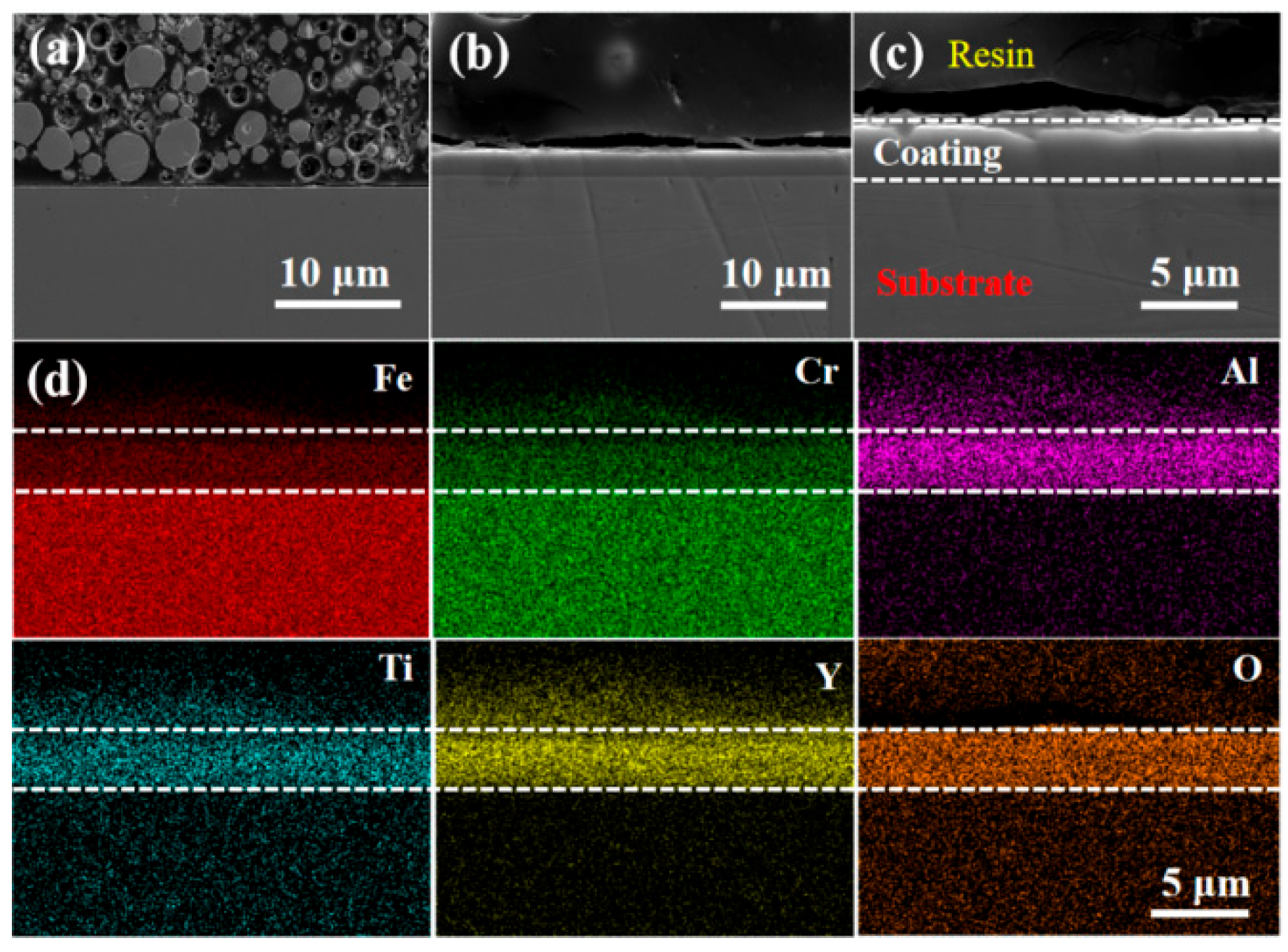
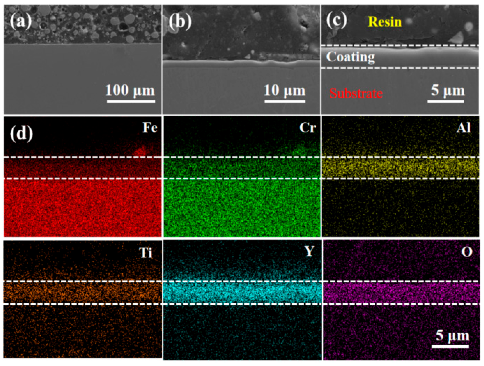
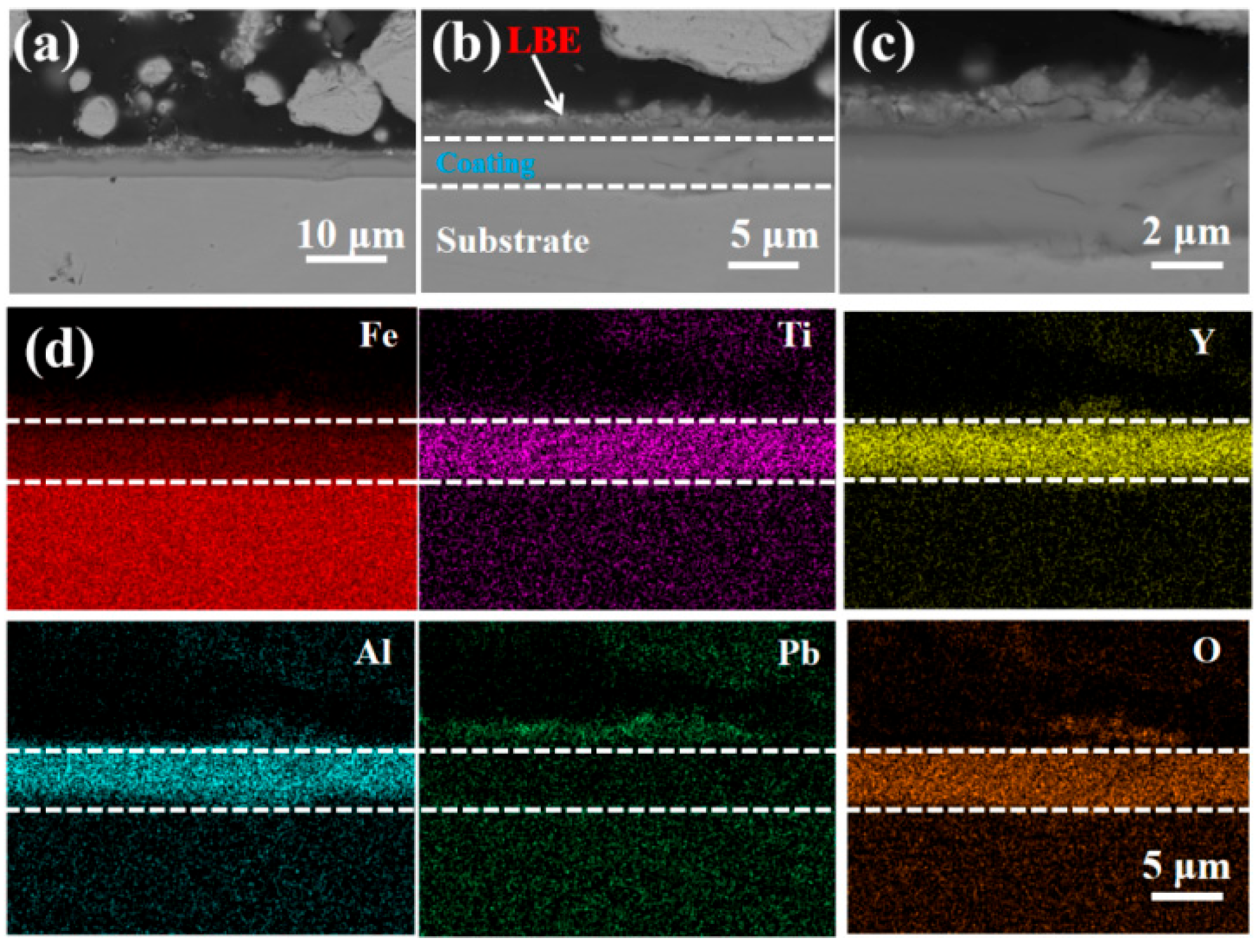
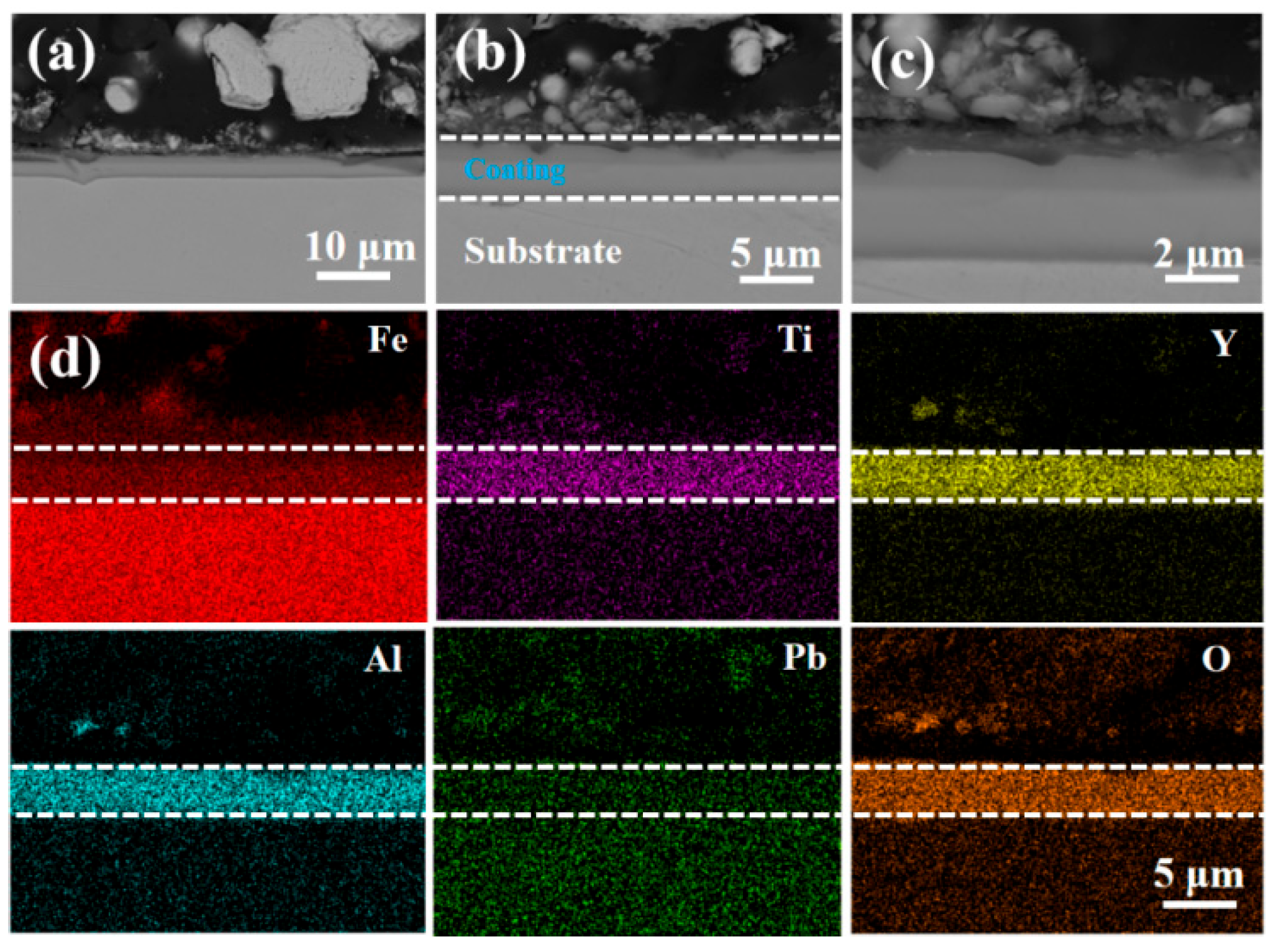
Figure 1 depicts a cross-sectional of the FeCrAlTi-ODS (S1) coating, complemented by the respective elemental distribution analysis. As Figure 1a–c shows, a clear interface is visible between the alloy coating and the 316L substrate material, with no detectable pores on the surface of the alloy coating and the 316L steel substrate, indicating a strong adhesion between the FeCrAlTi-ODS alloy coating and the substrate. Figure 1d displays the EDS mapping of the section, illustrating a uniform distribution of the deposited coating elements, with no signs of aggregation or segregation. As Figure 2 and Figure 3 show, similar to the S1 coating, the alloy coatings prepared under different negative bias voltages all have good quality, with no observed aggregation or segregation of elements. The thickness of the FeCrAlTi-ODS coatings prepared under different negative bias voltages varies. The entire cross-section can be divided into three parts: the epoxy resin section, the FeCrAlTi-ODS coating section, and the substrate material section. Each part has a dense structure, indicating that the controlled preparation of the FeCrAlTi-ODS coating has been achieved.
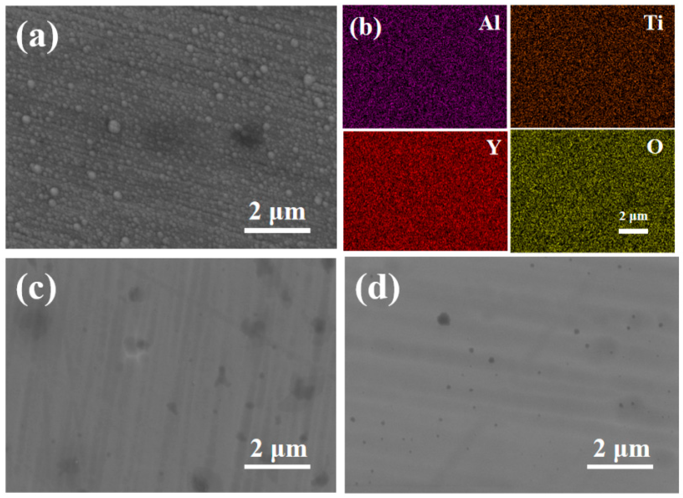
Figure 4 shows the SEM and EDS profiles of alloy coating under different bias voltages. As Figure 4a shows, the coating prepared without bias voltage exhibits some sizable particles on its surface. Figure 4b provides the local elements distribution map of the major elements in Figure 4a, revealing that the coating materials are evenly distributed without noticeable pores. Figure 4c,d shows that applying a certain bias voltage will enhance the intensity of the magnetron sputtering ion splash, thus improving the compactness of the film. Additionally, the surface SEM shows uniform scratches on the alloy coating, which originate from the polished substrate.
Table 3 presents the distribution of surface elements for the alloy coating fabricated at various bias voltages. The element content in the alloy coating has a certain deviation compared to the target materials, which could be due to the non-equilibrium characteristics inherent in the magnetron sputtering process. The alloy coating surface has adsorbed a large amount of oxygen elements from the air. Additionally, the sputtering power of each sector target is different, and the uneven distribution of the magnetic field on the target surface intensifies as the sputtering time increases [34].
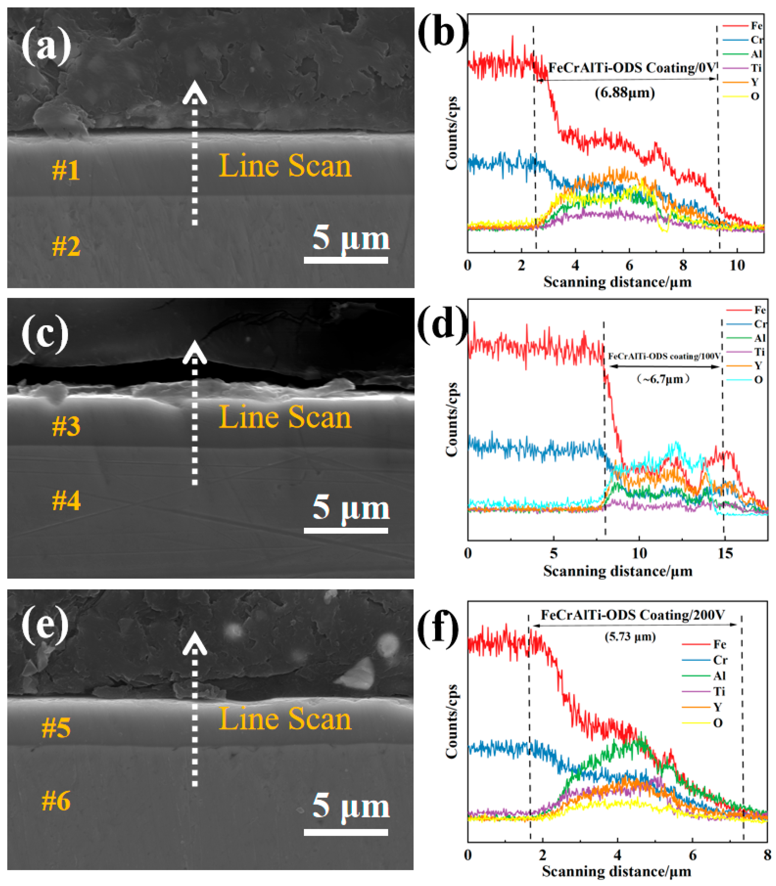
Figure 5 illustrates the thicknesses of the FeCrAlTi-ODS alloy coatings prepared under various bias voltages. Results show that the thicknesses are 6.88 μm at 0 V, 6.70 μm at 100 V, and 5.73 μm at 200 V, which decreases as the applied bias voltage increases, indicating that the coating deposition rate decreases with the increase of bias voltage. As Figure 5d shows, according to the differences in the content of Fe element, the entire structure is divided into the matrix material, the coating structure, and the resin structure. At the boundaries of each part, a relatively obvious fluctuation phenomenon of Fe element content occurs. Investigators [35,36] suggest that the deposited ion energy ( U K ) is related to the substrate bias voltage ( V s ) and the gas pressure ( p g ). It can be expressed by the relation shown in Equation (2):
U K D W V s / p g 1 / 2
Equation (2) shows that the ion deposition energy ( U K ) is directly proportional to the target ionization power ( D W ) and the substrate bias voltage ( V s ) and inversely proportional to the gas pressure ( p g ). In the process of ion sputtering, when the gas pressure ( p g ) and the target ionization power ( D W ) in the chamber remain unchanged, the deposited ion flux increases with the increase of the bias voltage ( V s ). The enhanced ion flux boosts ion bombardment and back-scattering on the coating surface, enhancing the mobility of deposited atoms on the substrate. The increase of bias voltage reduces the automatic deposition rate on the coating surface, and the larger ion flux promoted the migration and filling of deposition atoms on the matrix surface; therefore, the coating deposition rate decreases as the bias voltage increases. However, the decrease in coating thickness is not linear, but flattens as the bias voltage increases. When the bias voltage is excessively high, it can lead to some adverse effects. However, by applying an appropriate bias voltage, back-sputtering on the coating surface can be minimized, improving the film’s uniformity and density. Hence, it is essential to ascertain the optimal bias voltage tailored to the specific process conditions.
Table 4 illustrates the uniform enrichment of each element within the coating range, and no coating elements were detected in the substrate part. The coating is stable, and there is no element migration. It can be found that the main elements present in the substrate are Fe and Cr, which are the same as the components of 316L austenitic steel. This indicates that the magnetron sputtering process will not damage the structure of the substrate and demonstrates the rationality of the controllable preparation of the FeCrAlTi-ODS coating by magnetron sputtering.
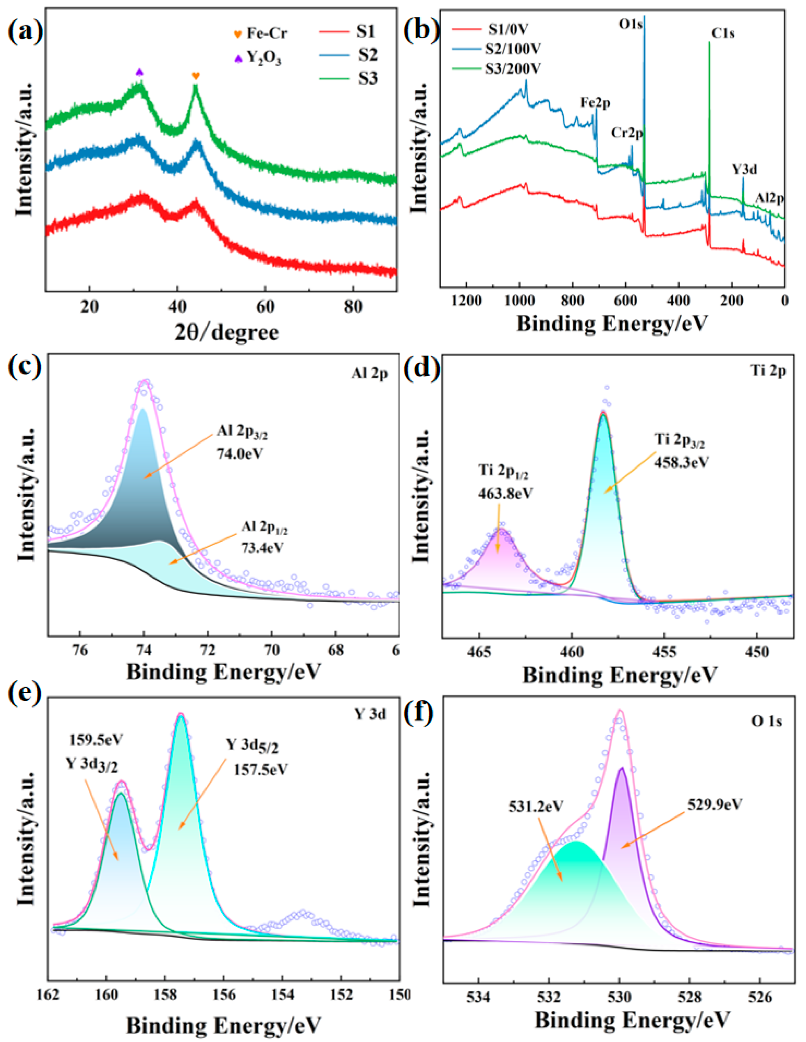
Figure 6a shows the GIXRD analysis of the surface of an alloy coating prepared under different bias voltages. GIXRD analysis indicates that the inclusion of the Y element markedly boosts the diffraction peak intensity associated with the Fe-Cr solid solution phase. Furthermore, the intensity of the diffraction peaks on the alloy coating’s surface significantly rises as the bias voltage increases. This phenomenon may be attributed to the energetic effects during the deposition process under high bias pressure, in which the diffusion and migration of deposition atoms is accelerated due to the bombardment of high-energy Ar+ ions. Consequently, this leads to different preferential growth orientations of the coating [37]. The deposited film is amorphous, with two broad peaks at 2θ = 33° and 2θ = 45°. No obvious diffraction peak of the Ti elements was observed in the GIXRD map, which may be related to the relatively low content of the Ti element.
Figure 6b shows the XPS spectrum of FeCrAlTi-ODS alloy coatings prepared under different bias voltages. The presence of O, Y, Ti, Al, Fe, and Cr elements on the alloy coating’s surface verifies the successful application of the FeCrAlTi-ODS alloy coating onto austenitic stainless steel. To study the chemical states of various elements, the fine spectra of Al, Ti, Y, and other elements in the alloy coating prepared under 100 V bias voltage were analyzed. As Figure 6c shows, the binding energy of 74.1 eV for Al 2p1/2 and 73.30 eV for Al 2p3/2, indicating the presence of Al elements. As Figure 6d shows, 458.3 eV and 463.8 eV correspond to the binding energy of Ti 2p3/2 and Ti 2p1/2 respectively, indicating the presence of Ti. As Figure 6e shows, the electron binding energies corresponding to Y 3d5/2 and Y 3d3/2 at 157.5 eV and 159.5 eV indicate that Y primarily exists in the alloy coating in various forms [38]. The absence of a metal Y 3d peak at 155.6 eV suggests that the content of metallic Y in the film is below the detection limit. As Figure 6f shows, according to the XPS manual, the fine spectra of O 1s at binding energies of 529.9 eV and 531.2 eV correspond to the O-Y bond and physical adsorbed oxygen O2−, respectively. This indicates that there is a certain amount of adsorbed oxygen in the coating structure, which also suggests that the coating contains a significant amount of O elements. As the applied bias during the coating process increases, the content of O-Y bonds rises. Although the samples were prepared by Ar+ sputtering, the metal–ceramic coatings prepared under magnetron sputtering conditions inevitably contain adsorbed oxygen.
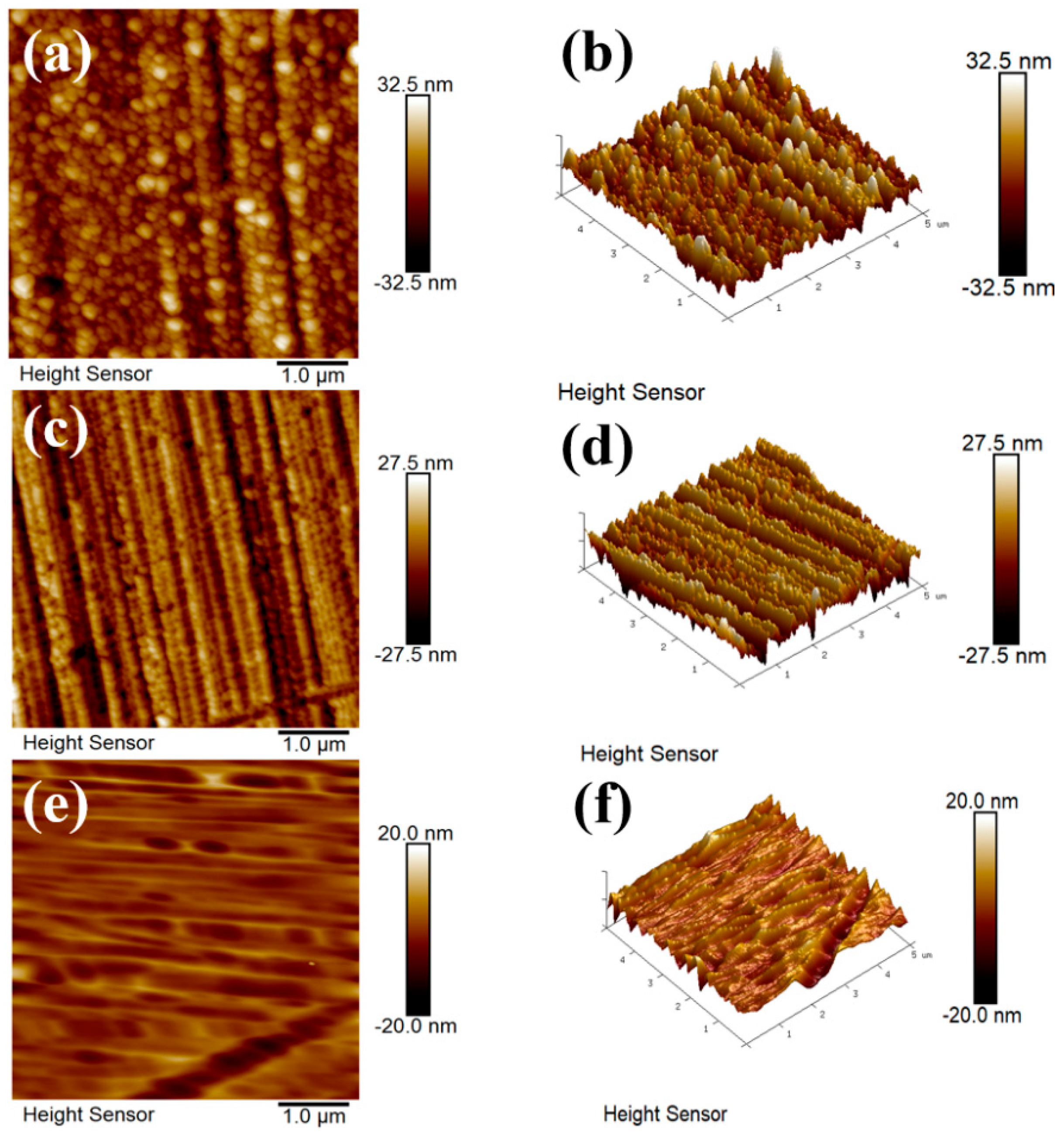
The roughness of FeCrAlTi-ODS coatings prepared under different bias voltages significantly shows the adhesion performance of the coating. Atomic force microscopy (AFM) was used to measure the roughness. As Figure 7 shows, the average roughness (Ra) of the alloy coatings prepared under 0 V, 100 V, and 200 V is 5.8 nm, 6.4 nm, and 2.2 nm, respectively. It can be observed that the surfaces of the S1 and S2 alloy coatings exhibit significant undulations, while the average roughness Ra of the S3 alloy coating material is notably reduced. Appropriate bias voltage can attract some Ar+, effectively cleaning impurities on the substrate, making the elemental arrangement more dense and orderly and reducing the impact of impurity particles on the flatness of the coating surface. As a result, it helps reduce coating roughness and enhance coating quality.

3.2. Mechanical Properties

As Figure 8 shows, the nanoindentation experiment was performed on the coating sample; the maximum load was set to 20 mN, and the load increased linearly with time. Figure 8a is the nanoindentation displacement-load curve, the alloy coating prepared under 200 V bias has the minimum pressure depth and a pressure depth of about 300 nm, while that of bare substrate 316L steel is about 450 nm. Figure 8b shows the pressure hardness (H) and elastic modulus (E) of the sample. As the bias voltage increases, the H and E of FeCrAlTi-ODS alloy coating are increased accordingly; the highest hardness reaches 11.52 GPa, and the highest elastic modulus reaches 172.89 GPa. However, the nano-hardness of the bare substrate 316L steel is only 5.49 GPa, and the coating promotes the nano-hardness by more than twice. For the evaluation of the friction performance of alloy coating, there are two important indicators based on H and E, namely H/E and H3/E2 [39]. H/E is commonly employed to characterize a material’s wear resistance and its capacity to withstand failure due to elastic strain. The high H/E ratio indicates that the material has better wear resistance. The ratio H3/E2 is indicative of a material’s resistance to plastic deformation under load contact, and the higher the value of H3/E2 of the material, the higher its resistance to plastic deformation. As Figure 8c shows, the wear resistance of the FeCrAlTi-ODS alloy coating prepared under different bias pressures is similar. Applying the alloy coating to 316L austenitic steel significantly enhances the mechanical characteristics of the base material compared to the substrate alone, and its nano-hardness and elastic modulus, wear resistance and plastic deformation resistance are improved in a large range.

3.3. Resistance to LBE Corrosion Properties

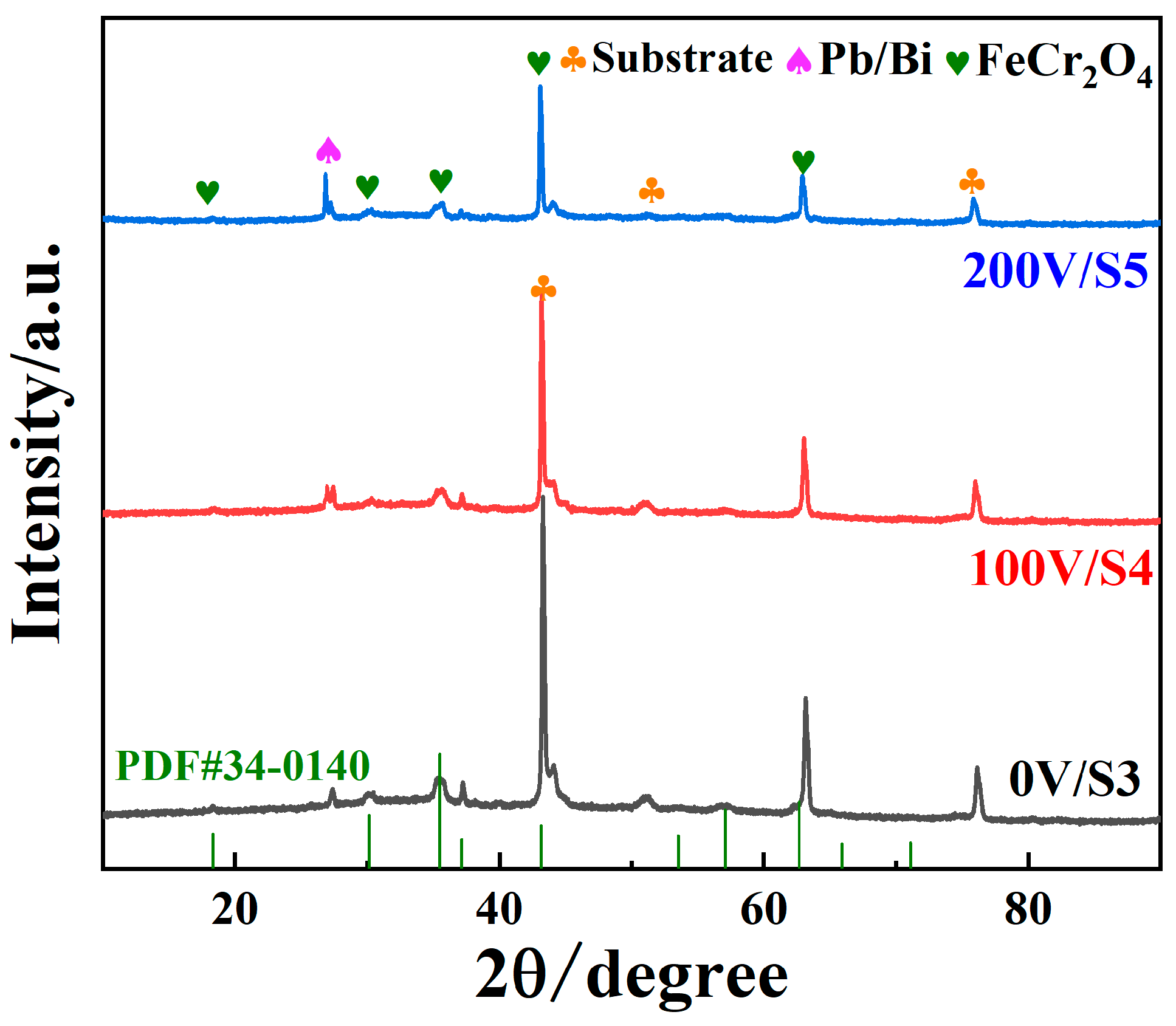
Research indicates that applying an alloy coating to stainless steel surfaces can efficiently shield the underlying material against corrosion by LBE [21,40,41]. To investigate the phase composition of the pattern surface following 100 h of LBE corrosion, as Figure 9 shows, GIXRD phase analysis was performed on the coating corrosion samples prepared under different bias voltages. According to the results, oxide formation occurred on the alloy coating’s surface. Other than the peak of removing the substrate elements, FeCr2O4 (PDF#34-0140) were mainly detected on the surface of the alloy coating, which is the composite oxide of Fe and Cr. Under the action of long corrosion, it is composed of Cr2O3 and Fe2O3, which has a good protective effect compared with the oxide of Fe and Cr. This indicates growth of coating surface oxides to prevent further oxidation of the substrate material. In general, the formation sequence of oxides is primarily related to Gibbs free energy, with alumina oxides preferentially forming compared to other observed oxides. However, the oxide growth primarily occurs through the outward diffusion of the coating’s metal elements; Fe and Cr elements in LBE solubility is low [42], its diffusion coefficient is relatively high, Al element atomic radius is larger, and serious lattice distortion leads to its slow diffusion. This impedes the diffusion of elements like Al and Ti, resulting in the higher mobility of Fe and Cr in liquid-phase LBE compared to Al and Ti [43]. Eventually, selective oxidation takes place as a result of varying diffusion rates among the alloy’s constituent elements [31].
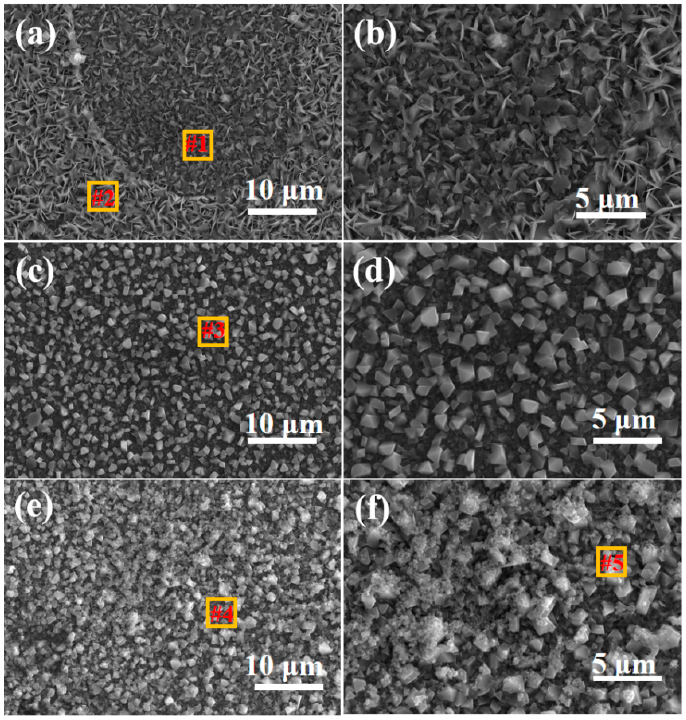
Figure 10 shows the SEM images of the surface of the prepared alloy coating after corrosion in LBE at 550 °C for 100 h. After a long period of LBE corrosion, a large number of granular oxides form on the surface. As Figure 10a,b shows, the S1 coating material is severely damaged. Its oxides have a flaky structure, and a large number of corrosion pits appear. There is a large accumulation of LBE residue that can further corrode the interior of the substrate along the generated holes, accelerating the corrosion process of the substrate and thus causing serious damage to the substrate. As Figure 10c,d shows, the coating prepared under a negative bias voltage of 100 V has the least LBE residue on its surface. The oxides are small in size and have a regular rhombic shape. After a long period of corrosion, the coating can still remain intact. As Figure 10e,f shows, the S3 coating surface forms relatively regular oxide particles. However, a large amount of LBE residue is present on the S3 surface, indicating that, after a long period of LBE corrosion, a large number of oxides of Pb and Bi alloys adhere to the surface of the S3 coating. The oxide particles in S2 and S3 coatings are different from those in the S1 coating, which illustrates the importance of applying a negative bias voltage during the coating preparation process.
Table 5 shows the atomic ratios of the elemental contents at various local positions in Figure 10. There is only a trace amount of LBE residue (0.14 at.% Pb) on the surface of the S2 alloy coating (at position #3). Compared with the LBE residue after corrosion of the S1 coating (at position #1, 1.97 at.% Pb) and the LBE residue after corrosion of the S3 coating (at position #5, 0.75 at.% Pb), the contents of Ti and Y elements on the surface of the S2 coating do not change significantly after corrosion, which can demonstrate the stability of the dispersed oxide particles. The S2 alloy coating shows better corrosion resistance to LBE.
In order to observe the corrosion resistance of the alloy coatings prepared under different bias voltages to LBE, SEM and EDS were used to analyze the corrosion cross-sections of different samples. Figure 11a–c are SEM images of the cross-section of Sample S1 after being corroded by LBE. The outermost layer is the residual LBE. It can be observed that the coating structure remains intact, and no LBE residue is found in the substrate part. As Figure 11d shows, in the EDS mapping image, various oxides can be observed, including the oxides of elements such as Fe, Al, and Ti. There is a certain amount of lead oxide on the surface of the coating. The LBE does not penetrate into the substrate, indicating that the prepared alloy coating can effectively protect the stainless-steel substrate material.
Figure 12a–c presents the SEM images of the cross-section of the S2 coating after being corroded by 550 °C LBE for 100 h. The outermost layer is the embedded resin, and no oxide layer or LBE residue can be seen on the surface of the coating. The penetration amounts of Pb and Bi elements are minimal, and the interface of the substrate part of the S2 coating is obvious. As Figure 12d shows, similarly, no obvious Pb element is detected in the substrate part, indicating that the LBE does not penetrate into the substrate, and the coating is well preserved. This shows that S2 alloy coating can improve the corrosion resistance of the coating to LBE and effectively inhibit the further penetration of LBE. Figure 13a–c is the SEM images of the cross-section of the S3 alloy coating after being corroded by LBE at 550 °C for 100 h, there is an obvious LBE alloy on the surface of the S3 alloy coating, but the LBE does not penetrate into the interior of the base material and cause serious corrosion. As Figure 13d shows, the LBE is still confined to the surface of the coating, and the presence of the dispersed oxide Y2O3 significantly enhances the coating’s resistance to LBE. In conclusion, the alloy coatings prepared under different bias voltages can still remain intact after being corroded by LBE. Cross-sectional images of the corroded coatings show that among these coatings, the one coating prepared under a negative bias voltage of 200 V exhibits the smallest thickness. Furthermore, the coating thickness can affect its corrosion resistance to LBE under certain conditions.
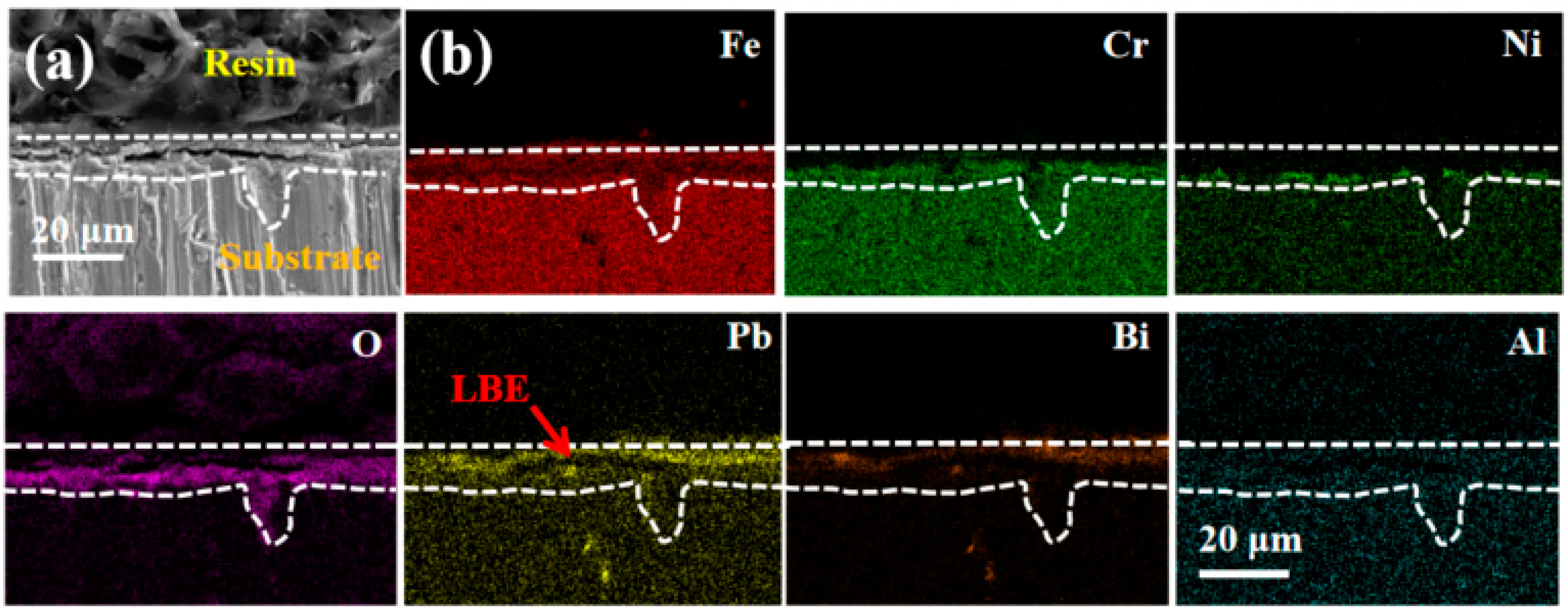
Figure 14 shows the cross-sectional SEM image and the corresponding EDS mapping image of the 316L austenitic steel base material after being corroded by LBE at 550 °C for 100 h. As Figure 14a shows, the surface of the base material is severely damaged, with a large area of corrosion pores appearing on the surface, and part of the surface of the base material is peeled off. As Figure 14b shows, there is an obvious penetration of the oxygen element on the surface of the base material. The penetration of the oxygen element into the interior of the base material will generate rapid oxidation channels, which will further accelerate the corrosion of the base material and seriously affect the service life of the base material, etc. The Ni element selectively penetrates and enriches on the surface of the base material, and the Pb element gradually dissolves into the interior of the base material [44]. An obvious oxide layer of Pb appears on the surface of the base material. The corrosion layer on the surface of the 316L austenitic steel base material is about 10 μm, and no dense oxide layer is formed on the surface of the base material to protect the base material.
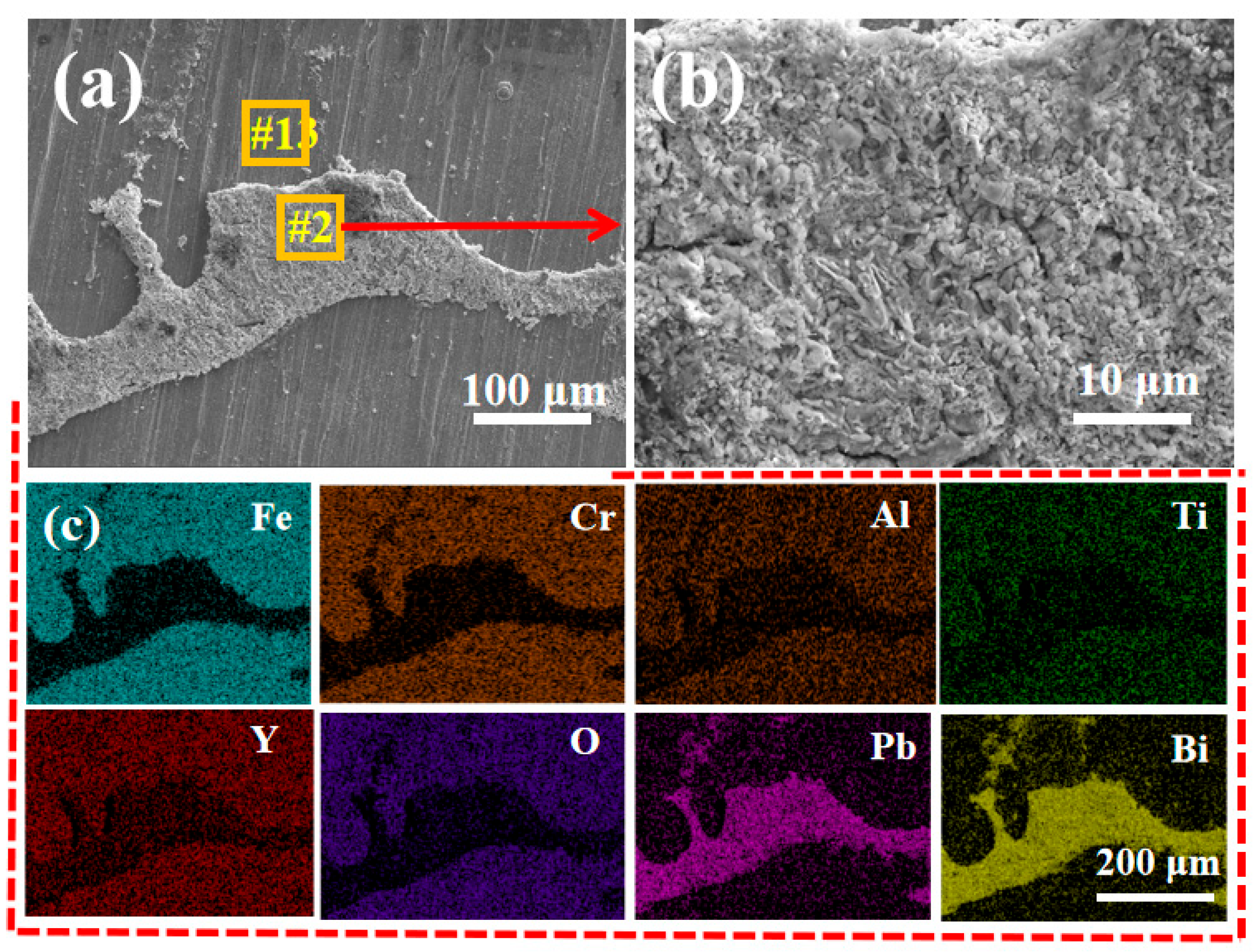
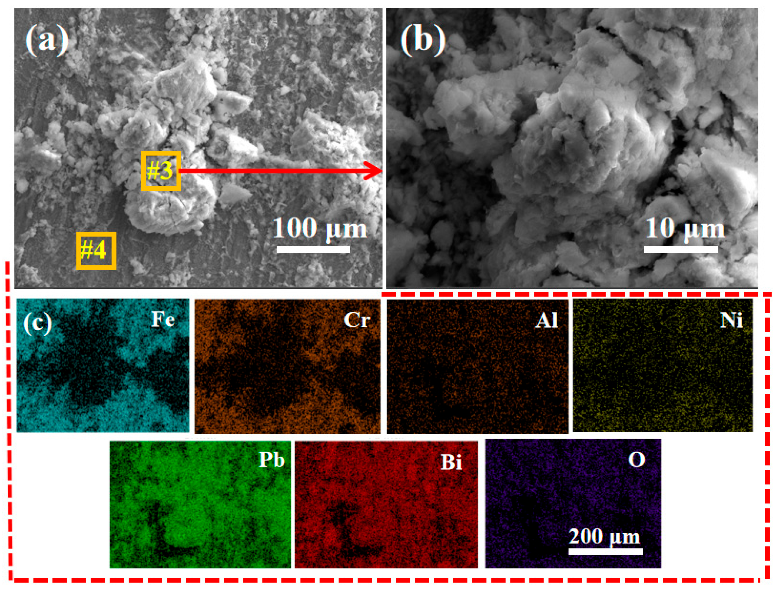
The surface of the coating structure that has not been cleaned with the mixed solution (CH3COOH:CH3CH2OH:H2O2 = 1:1:1) was characterized to further illustrate the corrosion resistance of the coating structure to LBE. Figure 15a,b presents SEM images of the residual substances on the surface of the S2 coating after being corroded by LBE at 550 °C for 100 h. A large amount of LBE residue exists on the surface, but the coating structure remains intact, with no obvious damage or cracks, and Figure 15b shows the LBE present on the surface. As Figure 15c shows, after a long-term corrosion by LBE, the coating structure in the area without LBE residue is well preserved (all elements in the coating exist stably, and there is no obvious enrichment phenomenon), indicating that the S2 coating has good stability during the LBE corrosion process, and the coating structure is not prone to severe dissolution or corrosion.
Figure 16 shows the SEM image and EDS energy spectrum of the surface residues of the 316L austenitic steel base material after being corroded by LBE at 550 °C for 100 h. It can be found that LBE is distributed on the entire surface of the base material. Under the condition of long-term corrosion at a low oxygen concentration, LBE has a strong dissolving and corroding effect on the base material. This also indicates to some extent that the wettability of the S2 coating and the base material to LBE is different, that is, less LBE adheres to the surface of the coating material, and it can effectively prevent the material from being corroded by the liquid medium. As Table 6 shows, after being corroded by LBE, only 0.36 at.% Pb and 0.14 at.% Bi (#1 position) are present on the surface of the S2 coating, there are only trace amounts of Pb and Bi elements on the surface. However, a large amount of LBE exists on the surface of the 316L austenitic steel. There are 1.41 at.% Pb and 4.33 at.% Bi (#4 position) on the surface of the 316L austenitic steel base material, and various lead oxides are formed. The 316L austenitic steel has a relatively high solubility in LBE, and the Ni element undergoes selective dissolution, which seriously affects the service life of the structural material [45,46]. The experimental results show that preparing a corrosion-resistant FeCrAlTi-ODS coating on the surface of the base material is one of the optional methods that can alleviate its tendency to dissolve and corrode.

4. Conclusions

In the present study, FeCrAlTi-ODS alloy coatings have been designed and applied on the surface of 316L steel, which was then exposed to aggressive molten LBE. Investigations were conducted into the micro-structure, mechanical properties, and LBE corrosion resistance. Based on the results, the principal conclusions can be summarized as follows:
  • According to SEM and GIXRD, the surface of FeCrAlTi-ODS coating prepared at different bias voltages is relatively uniform, without bad pores and defects. The surface EDS shows that the coating surface elements are evenly distributed, and the atom ratio of the surface elements is similar.
  • XPS analysis of the alloy coating surface shows the existence of diffusion oxide Y2O3 in the FeCrAlTi-ODS coating. Nanoindentation experiment shows that the applied bias voltage can effectively improve the binding force and mechanical properties of the alloy coating membrane, and its nano-hardness and elastic modulus can reach 11.52 GPa and 172.89 GPa. With the increase of the applied negative bias voltage, the thickness of the prepared coating decreases to a certain extent, and the coating thickness can affect the performance of the coating.
  • The LBE corrosion experiment at saturated oxygen concentration (550 °C, 100 h) shows that the S2 alloy coating has the least residual LBE on the surface, and the composite oxide FeCr2O4 of Fe and Cr is mainly formed on the surface. After the LBE corrosion, the coating can remain intact, indicating that it has good corrosion resistance effect on the substrate 316L steel. Compared with the uncoated 316L substrate material, the preparation of the alloy coating can effectively improve its LBE corrosion resistance.

Author Contributions

H.H.: Data curation, formal analysis, investigation, validation, writing—original draft. J.L.: Data curation, formal analysis, investigation. B.Z.: Conceptualization, validation. J.Z.: Conceptualization, validation. Z.L.: Funding acquisition, methodology, writing—review & editing. H.Z.: Funding acquisition, methodology, writing—review & editing. All authors have read and agreed to the published version of the manuscript.

Funding

The authors acknowledge the financial support from the Research and Development Platform of China National Nuclear Corporation (Grant No. WDZC-2023-AW-0323), the Scientific Research Business Fund Project of Heilongjiang Provincial Research Institutes (Grant No. CZJBKYF2023-02), the Key Research and Development Program of the Heilongjiang Academy of Sciences (Grant No. ZDYF2024YZN01), and the Specialized Capability Enhancement Project of Heilongjiang Academy of Sciences (Grant No. YSTS2025YZN01).

Institutional Review Board Statement

Not applicable.

Informed Consent Statement

Not applicable.

Data Availability Statement

The data underlying this article will be shared on reasonable request from the corresponding author.

Conflicts of Interest

The authors declare that they have no known competing financial interests or personal relationships that could have appeared to influence the work reported in this paper.

References

  1. Grasso, G.; Petrovich, C.; Mattioli, D.; Artioli, C.; Sciora, P.; Gugiu, D.; Bandini, G.; Bubelis, E.; Mikityuk, K. The core design of ALFRED, a demonstrator for the European lead-cooled reactors. Nucl. Eng. Des. 2014, 278, 287–301. [Google Scholar] [CrossRef]
  2. Kelly, J.E. Generation IV International Forum: A decade of progress through international cooperation. Prog. Nucl. Energy 2014, 77, 240–246. [Google Scholar] [CrossRef]
  3. Murty, K.L.; Charit, I. Structural materials for Gen-IV nuclear reactors: Challenges and opportunities. J. Nucl. Mater. 2008, 383, 189–195. [Google Scholar] [CrossRef]
  4. Legkikh, A.Y.; Askhadullin, R.S.; Martynov, P.N.; Melnikov, V.P.; Storozhenko, A.N. Conceptual aspects of melting unit vessel cooling by heavy liquid metal coolant. Nucl. Energy Technol. 2016, 2, 161–165. [Google Scholar] [CrossRef]
  5. Heinzel, A.; Weisenburger, A.; Müller, G. Corrosion behavior of austenitic steels in liquid lead bismuth containing 10−6 wt% and 10−8 wt% oxygen at 400–500 °C. J. Nucl. Mater. 2014, 448, 163–171. [Google Scholar] [CrossRef]
  6. Wang, H.; Xiao, J.; Wang, H.; Chen, Y.; Yin, X.; Guo, N. Corrosion Behavior and Surface Treatment of Cladding Materials Used in High-Temperature Lead-Bismuth Eutectic Alloy: A Review. Coatings 2021, 11, 364. [Google Scholar] [CrossRef]
  7. He, L.; Liu, C.; Lin, J.; Chen, Q.; Yang, J.; Zhang, R.; Yang, H.; Wang, Y.; Wang, J.; Long, J.; et al. Microstructure, oxidation and corrosion properties of FeCrAl coatings with low Al content prepared by magnetron sputtering for accident tolerant fuel cladding. J. Nucl. Mater. 2021, 551, 152966. [Google Scholar] [CrossRef]
  8. Zhang, W.; Zhong, Y.; Qiu, X.; Li, Q.; Yue, H.; Zhou, Y.; Deng, J.; Yang, J.; Liu, H.; Li, Q.; et al. Screening of the FeCrAl LBE corrosion-resistant coatings: The effect of Cr and Al contents. Surf. Coat. Technol. 2023, 462, 111054. [Google Scholar] [CrossRef]
  9. Yang, Y.; Li, Y.; Liang, Z.; Bai, P.; Nie, J.; Liu, S.; Chen, B.; Wei, S.; Guan, Q.; Cai, J. Continuous hot corrosion behaviour of an FeCrAlSi coating prepared by laser cladding. Surf. Coat. Technol. 2021, 421, 127424. [Google Scholar] [CrossRef]
  10. Dai, Y.; Boutellier, V.; Gavillet, D.; Glasbrenner, H.; Weisenburger, A.; Wagner, W. FeCrAlY and TiN coatings on T91 steel after irradiation with 72MeV protons in flowing LBE. J. Nucl. Mater. 2012, 431, 66–76. [Google Scholar] [CrossRef]
  11. Zhang, W.; Deng, J.; Zhou, M.; Zhong, Y.; Wu, L.; Mao, J.; Xu, X.; Zhou, Y.; Yang, J. Synergistic effect of simultaneous proton irradiation and LBE corrosion on the microstructure of the FeCrAl(Y) coatings. Corros. Sci. 2024, 229, 111874. [Google Scholar] [CrossRef]
  12. Zhang, P.; Yao, Z.; Wang, X.; Zheng, Y.; Cui, K.; Yao, R.; Lin, S.; Liu, Y.; Lu, S.; Wu, X. A novel FeCrAlW high entropy alloy coating for enhancing lead-bismuth eutectic corrosion resistance. J. Nucl. Mater. 2024, 589, 154844. [Google Scholar] [CrossRef]
  13. Zhang, L.; Shi, Y.; Ye, Q.; Yang, B. Enhanced Corrosion−Resistance of AlTiCrFeMoSi High−Entropy Alloy Coating by Magnetron Sputtering. Coatings 2023, 13, 332. [Google Scholar] [CrossRef]
  14. Deng, J.; Zhang, W.; Qiu, X.; Li, Q.; Chen, Q.; Yang, J.; Zhong, Y.; Zhu, C.; Liu, H.; Zhao, S.; et al. Effect of Au-ion irradiation on the morphology, microstructure and lead-bismuth eutectic corrosion behavior of refractory TiNbZrMoV high-entropy alloy coating. J. Nucl. Mater. 2023, 584, 154592. [Google Scholar] [CrossRef]
  15. Deng, J.; Yang, J.; Lv, L.; Zhang, W.; Chen, Q.; Zhou, M.; Zhu, C.; Liu, N.; Yang, J. Corrosion behavior of refractory TiNbZrMoV high-entropy alloy coating in static lead-bismuth eutectic alloy: A novel design strategy of LBE corrosion-resistant coating? Surf. Coat. Technol. 2022, 448, 128884. [Google Scholar] [CrossRef]
  16. Yang, J.; Zhao, K.; Wang, G.; Deng, C.; Liu, N.; Zhang, W.; Yang, J. Influence of coating thickness on microstructure, mechanical and LBE corrosion performance of amorphous AlCrFeTiNb high-entropy alloy coatings. Surf. Coat. Technol. 2022, 441, 128502. [Google Scholar] [CrossRef]
  17. Lyu, L.; Yang, J.; Zhou, M.; Yan, M.; Yang, J. Microstructure, mechanical properties and lead-bismuth eutectic corrosion behavior of (AlCrFeTiMo)NO and (AlCrFeTiNb)NO high entropy metal sublattice ceramic coatings. Vacuum 2023, 209, 111774. [Google Scholar] [CrossRef]
  18. Devia, D.M.; Restrepo-Parra, E.; Arango, P.J.; Tschiptschin, A.P.; Velez, J.M. TiAlN coatings deposited by triode magnetron sputtering varying the bias voltage. Appl. Surf. Sci. 2011, 257, 6181–6185. [Google Scholar] [CrossRef]
  19. Wu, Z.Y.; Zhao, X.; Liu, Y.; Cai, Y.; Li, J.Y.; Chen, H.; Wan, Q.; Yang, D.; Tan, J.; Liu, H.D.; et al. Lead-bismuth eutectic (LBE) corrosion behavior of AlTiN coatings at 550 and 600 °C. J. Nucl. Mater. 2020, 539, 152280. [Google Scholar] [CrossRef]
  20. Wan, Q.; Wu, Z.Y.; Liu, Y.; Yang, B.; Liu, H.D.; Ren, F.; Wang, P.; Xiao, Y.Y.; Zhang, J.; Zhang, G.D. Lead-bismuth eutectic (LBE) corrosion mechanism of nano-amorphous composite TiSiN coatings synthesized by cathodic arc ion plating. Corros. Sci. 2021, 183, 109264. [Google Scholar] [CrossRef]
  21. Zhong, Y.; Zhang, W.; Chen, Q.; Yang, J.; Zhu, C.; Li, Q.; Yang, J.; Liu, N.; Yang, J. Effect of LBE corrosion on microstructure of amorphous Al2O3 coating by magnetron sputtering. Surf. Coat. Technol. 2022, 443, 128598. [Google Scholar] [CrossRef]
  22. Yin, X.; Li, X.; Wang, H.; Zhao, K.; Wang, J.; Chen, L.; Wu, Z.; Chen, Y. The Corrosion Behavior of Al/Al2O3 Composite Films with Ultra-Dense Structure Exposed to Lead-Bismuth Eutectic at 450 to 650 °C. Coatings 2023, 13, 1274. [Google Scholar] [CrossRef]
  23. Li, H.; Bai, P.; Lin, Z.; Zhang, J.; Tang, Q.; Pan, Y. Corrosion resistance in Pb-Bi alloy of 15-15Ti steel coated with Al2O3/SiC bilayer thin films by magnetron sputtering. Fusion Eng. Des. 2017, 125, 384–390. [Google Scholar] [CrossRef]
  24. Heinzel, A.; Weisenburger, A.; Müller, G. Long-term corrosion tests of Ti3SiC2 and Ti2AlC in oxygen containing LBE at temperatures up to 700 °C. J. Nucl. Mater. 2016, 482, 114–123. [Google Scholar] [CrossRef]
  25. Bentzel, G.W.; Ghidiu, M.; Griggs, J.; Lang, A.; Barsoum, M.W. On the interactions of Ti2AlC, Ti3AlC2, Ti3SiC2 and Cr2AlC with pure sodium at 550 °C and 750 °C. Corros. Sci. 2016, 111, 568–573. [Google Scholar] [CrossRef]
  26. Jiang, H.; Zhao, X.; Cao, S.; Wang, D.; Zhu, Q.; Lei, Y. Improvement of the mechanical properties and LBE cavitation erosion resistance of laser cladded FeCrAlTiC coating by Y2O3 addition. Mater. Lett. 2022, 326, 132882. [Google Scholar] [CrossRef]
  27. Zhu, C.; Zhang, W.; Zhou, M.; Lv, L.; Zhong, Y.; Li, Q.; Zhou, Y.; Yang, J. Effect of Y2O3 content on microstructure and corrosion behavior of ZrO2 coatings in liquid Lead-Bismuth eutectic. Mater. Chem. Phys. 2023, 309, 128392. [Google Scholar] [CrossRef]
  28. Zhao, B.-L.; Wang, L.; Zhang, L.-F.; Ke, J.-G.; Xie, Z.-M.; Yang, J.-F.; Wang, X.-P.; Hao, T.; Liu, C.-S.; Wu, X.-B. Effect of Nano-Y2O3 Content on Microstructure and Mechanical Properties of Fe18Cr Films Fabricated by RF Magnetron Sputtering. Nanomaterials 2021, 11, 1754. [Google Scholar] [CrossRef] [PubMed]
  29. Song, L.; Wang, X.; Wang, L.; Zhang, Y.; Liu, W.; Jiang, W.; Zhang, T.; Fang, Q.; Liu, C. Fabrication and characterization of He-charged ODS-FeCrNi films deposited by a radio-frequency plasma magnetron sputtering technique. Plasma Sci. Technol. 2017, 19, 045502. [Google Scholar] [CrossRef]
  30. Kurata, Y. Corrosion behavior of cold-worked austenitic stainless steels in liquid lead–bismuth eutectic. J. Nucl. Mater. 2014, 448, 239–249. [Google Scholar] [CrossRef]
  31. Yamaki, E.; Ginestar, K.; Martinelli, L. Dissolution mechanism of 316L in lead–bismuth eutectic at 500 °C. Corros. Sci. 2011, 53, 3075–3085. [Google Scholar] [CrossRef]
  32. Gromov, B.F.; Orlov, Y.I.; Martynov, P.N.; Ivanov, K.D.; Gulevsky, V.A. Physical-Chemical Principles of Lead-Bismuth Coolant Technology. In Liquid Metal Systems: Material Behavior and Physical Chemistry in Liquid Metal Systems 2; Borgstedt, H.U., Frees, G., Eds.; Springer: Boston, MA, USA, 1995; pp. 339–343. [Google Scholar]
  33. Yang, J.; Shi, K.; Zhang, W.; Chen, Q.; Ning, Z.; Zhu, C.; Liao, J.; Yang, Y.; Liu, N.; Zhang, W.; et al. A novel AlCrFeMoTi high-entropy alloy coating with a high corrosion-resistance in lead-bismuth eutectic alloy. Corros. Sci. 2021, 187, 109524. [Google Scholar] [CrossRef]
  34. Xu, Y.; Li, G.; Xia, Y. Synthesis and characterization of super-hard AlCrTiVZr high-entropy alloy nitride films deposited by HiPIMS. Appl. Surf. Sci. 2020, 523, 146529. [Google Scholar] [CrossRef]
  35. Bradley, R.M.; Harper, J.M.E.; Smith, D. Theory of thin-film orientation by ion bombardment during deposition. J. Appl. Phys. 1986, 60, 4160–4164. [Google Scholar] [CrossRef]
  36. Rauschenbach, B.; Helming, K. Implantation-induced texture. Nucl. Instrum. Methods Phys. Res. Sect. B Beam Interact. Mater. At. 1989, 42, 216–223. [Google Scholar] [CrossRef]
  37. Zeng, X.K.; Li, Y.T.; Zhang, X.D.; Liu, M.; Ye, J.Z.; Qiu, X.L.; Jiang, X.; Leng, Y.X. Effect of bias voltage on the structure and properties of CuNiTiNbCr dual-phase high entropy alloy films. J. Alloys Compd. 2023, 931, 167371. [Google Scholar] [CrossRef]
  38. Zhang, J.; Li, X.; Wang, Y.; Liu, S. Synthesis and characterization of Y2O3 nanoparticles and nanorods in magnetron sputtered Ti-Y alloy films. Appl. Phys. A 2012, 110, 465–470. [Google Scholar] [CrossRef]
  39. Chen, X.; Du, Y.; Chung, Y.-W. Commentary on using H/E and H3/E2 as proxies for fracture toughness of hard coatings. Thin Solid Film. 2019, 688, 137265. [Google Scholar] [CrossRef]
  40. Chen, Y.; Hu, L.; Qiu, C.; He, B.; Zhou, L.; Zhao, J.; Li, Y. Influence of LBE Temperatures on the Microstructure and Properties of Crystalline and Amorphous Multiphase Ceramic Coatings. Coatings 2019, 9, 543. [Google Scholar] [CrossRef]
  41. Peng, X.; Tang, Y.; Ding, X.; Lu, Z.; Hou, S.; Zhou, J.; Han, S.; Lü, Z.; Lu, G.; Wu, Y. Fe-based amorphous coating prepared using high-velocity oxygen fuel and its corrosion behavior in static lead-bismuth eutectic alloy. Int. J. Miner. Metall. Mater. 2022, 29, 2032–2040. [Google Scholar] [CrossRef]
  42. Zhang, J.; Li, N. Review of the studies on fundamental issues in LBE corrosion. J. Nucl. Mater. 2008, 373, 351–377. [Google Scholar] [CrossRef]
  43. Xu, B.; Zhang, J.; Ma, S.; Xiong, Y.; Huang, S.; Kai, J.J.; Zhao, S. Revealing the crucial role of rough energy landscape on self-diffusion in high-entropy alloys based on machine learning and kinetic Monte Carlo. Acta Mater. 2022, 234, 118051. [Google Scholar] [CrossRef]
  44. Lambrinou, K.; Charalampopoulou, E.; Van der Donck, T.; Delville, R.; Schryvers, D. Dissolution corrosion of 316L austenitic stainless steels in contact with static liquid lead-bismuth eutectic (LBE) at 500 °C. J. Nucl. Mater. 2017, 490, 9–27. [Google Scholar] [CrossRef]
  45. Chen, Q.; Bai, F.; Wang, P.; Yang, J.; Zhu, C.; Zhang, W.; Liu, H.; Zhong, Y.; Deng, J.; Liu, N.; et al. Microstructure response and lead-bismuth eutectic corrosion behavior of 11Cr1Si ferritic/martensitic steel after Au-ion irradiation. Corros. Sci. 2022, 198, 110101. [Google Scholar] [CrossRef]
  46. Wu, W.; Ran, G.; Li, Y.; Cong, S.; Ye, C.; Zhang, R.; Sun, Y. Early corrosion behaviour of irradiated FeCrAl alloy in a simulated pressurized water reactor environment. Corros. Sci. 2020, 174, 108824. [Google Scholar] [CrossRef]
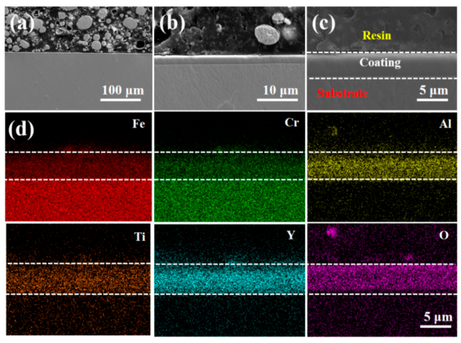
Figure 1. SEM analysis of the as-deposited FeCrAlTi-ODS (S1) alloy coating. (ac) cross-sectional SEM images; (d) cross-sectional EDS mapping.
Coatings 15 00942 g001
Figure 2. SEM analysis of the as-deposited FeCrAlTi-ODS (S2) alloy coating (ac) cross-sectional SEM images; (d) cross-sectional EDS mapping.
Coatings 15 00942 g002
Figure 3. SEM analysis of the as-deposited FeCrAlTi-ODS (S3) alloy coating (ac) cross-sectional SEM images; (d) cross-sectional EDS mapping.
Coatings 15 00942 g003
Figure 4. Surfaces of FeCrAlTi-ODS alloy coating prepared under different bias voltages (a) micro-topography of S1 coating; (b) local element distribution of S1 coating; (c) micro-topography of S2 coating and (d) micro-topography of S3 coating.
Coatings 15 00942 g004
Figure 5. Cross-sectional morphologies of FeCrAlTi-ODS coatings prepared under different negative bias voltages and corresponding EDS line. Scanning energy spectrum diagrams (a,b) S1 coating; (c,d) S2 coating; (e,f) S3 coating.
Coatings 15 00942 g005
Figure 6. FeCrAlTi-ODS alloy coatings prepared under different bias voltages (a) surface GIXRD; (b) XPS spectrum; (cf) fine spectra of FeCrAlTi-ODS alloy coating XPS prepared under 100 V bias voltage.
Coatings 15 00942 g006
Figure 7. AFM 2D images and 3D surface images of FeCrAlTi-ODS coating prepared under different negative bias voltages (a,b) S1 coating; (c,d) S2 coating; (e,f) S3 coating.
Coatings 15 00942 g007
Figure 8. Substrate and FeCrAlTi-ODS alloy coating prepared under different bias voltages. (a) nano-entation displacement-load curve; (b) H and E; (c) H/E and H3/E2.
Coatings 15 00942 g008
Figure 9. GIXRD profile after LBE corrosion of FeCrAlTi-ODS alloy coating.
Coatings 15 00942 g009
Figure 10. Surface SEM images of FeCrAlTi-ODS coatings prepared under different negative bias voltages after 100 h of 550 °C LBE corrosion. (a,b) S1 coating; (c,d) S2 coating; (e,f) S3 coating.
Coatings 15 00942 g010
Figure 11. (ac) S1 alloy coating cross-section after 100 h corrosion of 550 °C LBE; (d) EDS mapping of (b).
Coatings 15 00942 g011
Figure 12. (ac) S2 alloy coating cross-section after 100 h corrosion of 550 °C LBE; (d) EDS mapping of (b).
Coatings 15 00942 g012
Figure 13. (ac) S3 alloy coating cross-section after 100 h corrosion of 550 °C LBE; (d) EDS mapping of (b).
Coatings 15 00942 g013
Figure 14. (a) SEM diagram; (b) corresponding EDS mapping diagram of 316L of stainless steel corroded by 550 °C LBE for 100 h.
Coatings 15 00942 g014
Figure 15. (a,b) SEM diagram of the residual substances on the surface of the S2 alloy coating after 100 h of corrosion with 550 °C LBE; (c) EDS mapping diagram of (a).
Coatings 15 00942 g015
Figure 16. (a,b) SEM diagram of residual substances on the surface of 316L stainless steel after 100 h of corrosion with 550 °C LBE; (c) EDS mapping diagram of (a).
Coatings 15 00942 g016
Table 1. The chemical compositions of the 316L steel substrates (at.%).
FeCrNiMoMnSi
68.817.99.51.21.81.3
Table 2. Comprehensive parameters for the deposition of FeCrAlTi-ODS coatings.
ParametersValue
Base pressure3 × 10−4 Pa
Substrate temperature150 °C
Deposition pressure0.6 Pa
Air flow rate120 Sccm
Deposition time4 h
Target-substrate distance4 cm
Negative substrate bias0 V/100 V/200 V (S1/S2/S3)
Table 3. Elements distribution of FeCrAlTi-ODS alloy coating prepared under different bias voltages (at.%).
VoltageFeCrAlTiYO
0 VBal.6.975.161.215.9150.85
100 VBal.7.156.681.945.0855.89
200 VBal.9.625.211.504.5549.11
Table 4. The chemical compositions corresponding to the positions indicated in Figure 5 (at.%).
FeCrAlTiYO
#123.778.807.092.626.4951.23
#276.0021.640002.36
#322.958.798.612.998.5048.16
#476.6421.650001.71
#521.498.138.242.859.4049.89
#675.76 21.120003.12
Table 5. Elemental atomic ratios of various local regions after LBE. Corrosion of FeCrAlTi-ODS coating in Figure 10.
FeCrAlTiYOPbBi
#119.324.452.881.443.0666.521.970.36
#224.618.744.712.815.9351.091.730.38
#319.243.872.941.293.1669.360.140
#424.717.482.972.545.5056.490.310
#523.643.191.750.982.5867.010.750.10
Table 6. Figure 15a and Figure 16a show the proportional of each element.
PositionFeCrAlTiYNiOPbBi
#148.6220.545.341.494.4819.030.360.14
#20.7900.380066.380.1732.28
#32.700.750.130.5962.820.7832.23
#450.2011.780.4712.7219.091.414.33
Disclaimer/Publisher’s Note: The statements, opinions and data contained in all publications are solely those of the individual author(s) and contributor(s) and not of MDPI and/or the editor(s). MDPI and/or the editor(s) disclaim responsibility for any injury to people or property resulting from any ideas, methods, instructions or products referred to in the content.