Article

Near-Nozzle Atomization Characteristics in Air-Assisted Spraying: Integrated VOF-DPM Modeling and Experimental Validation

1
Department of Petroleum, Engineering University of the Joint Logistic Support Force, Chongqing 401331, China
2
National Engineering Research Center for Disaster and Emergency Rescue Equipment, Engineering University of the Joint Logistic Support Force, Chongqing 401331, China
*
Authors to whom correspondence should be addressed.
Coatings 2025, 15(8), 939; https://doi.org/10.3390/coatings15080939
Submission received: 15 July 2025 / Revised: 6 August 2025 / Accepted: 9 August 2025 / Published: 11 August 2025
(This article belongs to the Section Surface Characterization, Deposition and Modification)

Abstract

Near-nozzle atomization characteristics in air-assisted spraying were investigated through a novel 3D transient model integrating Volume-of-Fluid and Large Eddy Simulation (VOF-DPM) methods, with experimental validation of droplet distributions (Malvern analyzer) and coating thickness profiles. Key findings reveal that (1) the spray field stabilizes within 30 mm downstream, achieving 80% atomization efficiency (droplets ≤ 100 μm) at 27.5 mm axial distance; (2) radial momentum originates dually from fan-shaped airflow (max 595 m/s) and transverse motion induced by central atomizing air entrainment—a previously unreported mechanism; (3) paint loading delays flow stabilization to 2.5 ms (vs. 0.7 ms for gas-only flow) while reducing peak axial velocity by 18%–22% due to gas–liquid momentum exchange; (4) auxiliary and fan airflows synergistically constrain dispersion, forming elliptical sprays with characteristic cone angles of 61.7° (short axis) and 99.1° (long axis). Significantly, surface tension plays a dual role in inhibiting droplet atomization while promoting ligament pinch-off at 8.1 mm breakup length. These results provide the first quantitative characterization of gas–liquid interactions in near-nozzle regions, enabling precise parameter control for enhanced coating uniformity on complex surfaces.

Graphical Abstract

1. Introduction

The increasing diversification of spray products in industrial manufacturing has led to more complex and varied target surfaces [1]. Traditional approaches relying on simple path planning and ill-defined relationships between spraying parameters and coating quality are no longer sufficient. This represents a significant challenge for quality control in complex surface spraying and hinders the intelligent advancement of spraying processes [2].
A fundamental limitation lies in the inadequate understanding of spray atomization mechanisms and characteristics. This knowledge gap impedes the rational and dynamic setting of spraying parameters, as well as the planning of feasible motion paths, ultimately compromising coating quality on complex geometries [2]. Consequently, an in-depth investigation of spray atomization characteristics is crucial for addressing quality control issues in complex surface spraying.
Early studies of paint-atomizing flow fields employed techniques like the magnesium oxide method [3]. However, these suffered from poor measurement accuracy and could only capture limited droplet size data per measurement. To acquire comprehensive spray information non-invasively, optical measurement techniques—including digital holographic microscopy [4], particle image velocimetry (PIV) [5], and planar laser-induced fluorescence (PLIF) [6]—have been applied. Researchers have made significant progress using these methods. For instance, Domnick et al. [7] characterized droplet concentration in far-field regions, Wang et al. [8] measured droplet velocities in atomized flows, Mark et al. [9] analyzed electrostatic spray painting, and Ye et al. [10] quantified droplet sizes from rotary cup atomizers. Despite these advances, optical techniques remain constrained by inherent limitations and the extreme complexity of the near-nozzle region in high-speed spray flows, leaving the atomization process in this critical zone poorly understood.
Advances in computational fluid dynamics (CFD) platforms have established numerical simulation as a powerful tool for probing flow field characteristics [11]. Xiang Yuting [12] simulated initial atomization and breakup mechanisms of liquid films from centrifugal nozzles using Volume of Fluid (VOF) and Large Eddy Simulation (LES), validating results with high-speed photography. Fogliati et al. [13] applied a Eulerian model to analyze paint jet deformation and breakup near the nozzle, finding droplet sizes followed a Rosin–Rammler distribution beyond a certain expansion distance. Xie et al. [14] used the Taylor Analogy Breakup (TAB) model to predict secondary droplet breakup and resulting diameters, observing that increasing fan-shaped air pressure transformed the gas-phase flow field cross-section from circular to elliptical. While numerous studies exist on paint atomization [15,16,17,18,19], most focus on alternative methods such as rotary cup or airless spraying, whose atomization principles differ substantially from air spray systems. This limits the applicability of existing findings to air spray processes. Furthermore, current research methodologies exhibit considerable limitations, resulting in a superficial understanding of air spray atomization characteristics—often reduced to empirical observations like the need for higher atomization pressures with increased paint flow rate or viscosity.
To bridge these critical gaps in understanding the fundamental mechanisms governing air-assisted spray atomization, this study implements a three-dimensional transient numerical model of the air spray atomization flow field. The simulation accuracy was verified through experimental measurements of droplet size distributions and coating thickness profiles. Utilizing the validated numerical results, we quantify gas-phase properties and paint-phase distributions (spatial position, velocity, and particle size) within the three-dimensional spray field. These analyses provide mechanistic insights into atomization characteristics specific to air-assisted spraying systems.

2. Multi-Scale Numerical Simulation of Paint Atomization

2.1. Mathematical Model

To enhance computational efficiency while maintaining model fidelity, key simplifications are adopted: (1) the paint is modeled as an incompressible Newtonian fluid due to its relatively low viscosity, and (2) solvent evaporation and thermal effects are neglected, justified by the transient nature of atomization (occurring over milliseconds) [20]. The atomization process is characterized as turbulent gas–liquid two-phase flow; consequently, the developed model integrates governing equations for both gas–liquid motion and turbulence, formulated according to established multiphase flow approaches [21].

2.2. Numerical Simulation

The numerical simulation process, outlined in Figure 1, involved solving the mathematical model for paint atomization. Key steps included model formulation, computational domain definition, mesh generation, solver setup, equation solution, and output generation for experimental validation. Simulations were performed using ANSYS Fluent 19.0. While Section 2.1 details the mathematical model, this section focuses on the computational domain, mesh strategy, and solver configuration.
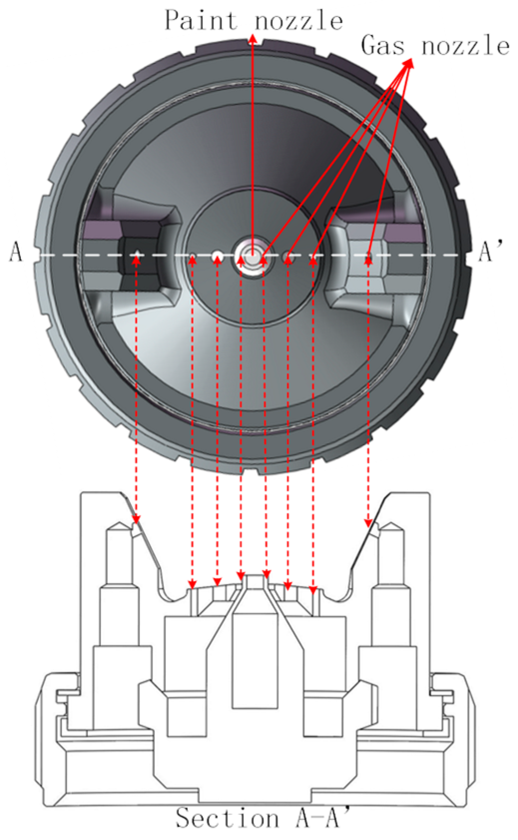
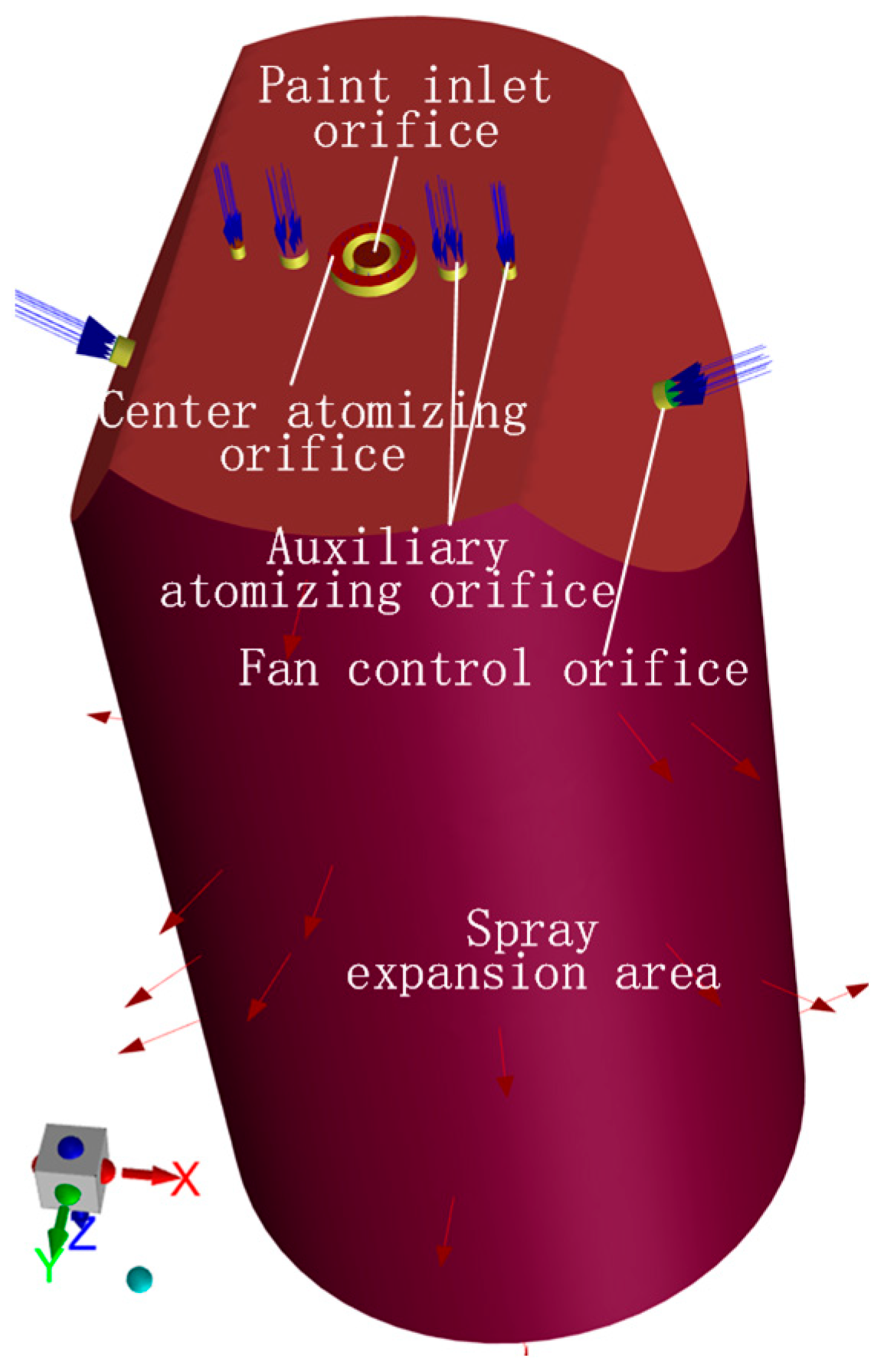
The W-71 paint spray gun (Iwata Co., Ltd., Tokyo, Japan) served as the basis for the model. The atomizing cap features a central atomizing orifice (Internal diameter φ = 3 mm, External diameter ψ = 2 mm), four symmetrically distributed auxiliary atomizing orifices (φ = 1 mm), and two fan-shaped atomizing orifices (φ = 1 mm), with the paint nozzle (φ = 1.3 mm) located centrally (Figure 2). Non-critical structural elements were simplified based on the physical atomization process. The computational domain was constructed using Ansys SpaceClaim, with its origin at the paint nozzle center. A Cartesian coordinate system defined the spray flow field: X-axis (short axis), Y-axis (long axis), and Z-axis (normal to the nozzle plane). The outer flow field extended radially 12 mm and axially 50 mm downstream (Figure 3).
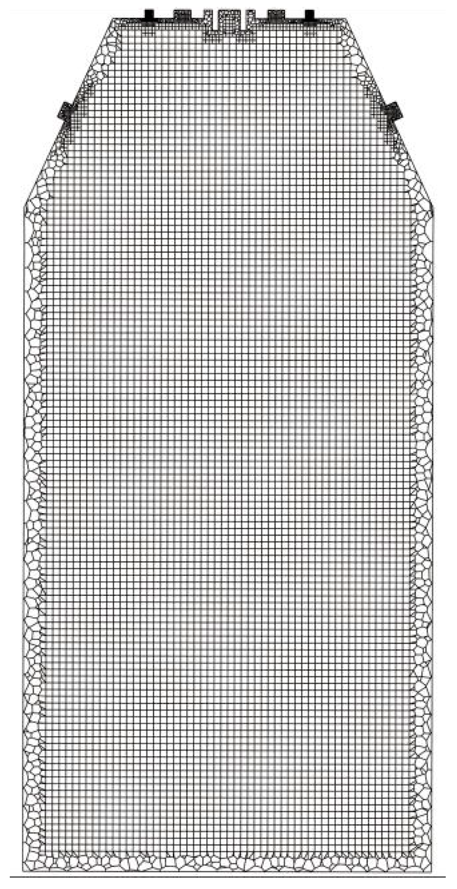
Given the complex geometry and the requirement for high-fidelity atomization simulation, a hybrid Hexcore meshing strategy was employed. Grid refinement was applied near walls and in regions anticipated to have large physical gradients. Dynamic adaptive mesh refinement was activated during calculations to further enhance resolution where needed. A representative cross-section of the final mesh is shown in Figure 4.
The gas phase (primary) and liquid paint phase (secondary) were defined, with physical properties (density, viscosity, surface tension) measured using standard instruments (densitometer, viscosity cup, surface tension meter). Boundary conditions are specified in Table 1.
The transient simulation employed an adaptive time step, starting at 1 × 10⁻⁷ s, with a total simulated physical time of 2.5 ms. The pressure–velocity coupling was handled by the SIMPLEC algorithm. Convection terms in the flow and scalar equations were discretized using second-order upwind schemes, while transient terms used a first-order implicit formulation.
Convergence was monitored through solution residuals. Figure 5 demonstrates good convergence behavior throughout the simulation. Computations were executed on a system equipped with an Intel Xeon Gold 6242 CPU. Utilizing 60 CPU cores, a single multiscale paint atomization simulation required approximately 54 h. This represents a significant reduction (approximately two-thirds) compared to the 150 h needed for an equivalent simulation using a Euler–Euler based model [20].
Figure 6 visualizes the post-processed flow field at 2.5 ms using an iso-surface of paint volume fraction (α_paint = 0.002), encompassing the full computational domain (Z = 50 mm). The continuous liquid phase is rendered in blue, while discrete paint droplets are represented by proportionally scaled black spheres. Key observations reveal that initial atomization is driven by the interaction of liquid paint with high-speed air jets emanating from the central, auxiliary, and fan-shaped orifices. The resulting atomized flow field comprises both finely atomized droplets and larger discontinuous ligaments/droplets. Droplet density is observed to be higher along the central axis (Z-axis) compared to the periphery. Furthermore, analysis of the transient paint volume fraction evolution indicates that the flow field has essentially stabilized at 30 mm downstream of the nozzle exit.

2.3. Experimental Validation

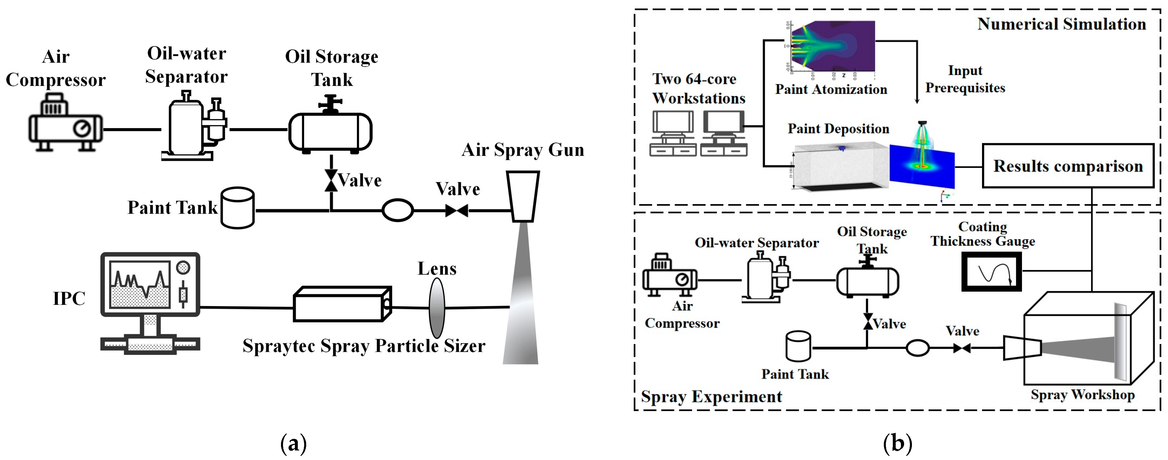
Experimental validation was performed to assess the accuracy of the numerical simulations. Validation focused on spray droplet size distribution and coating thickness, utilizing the platforms shown in Figure 7.
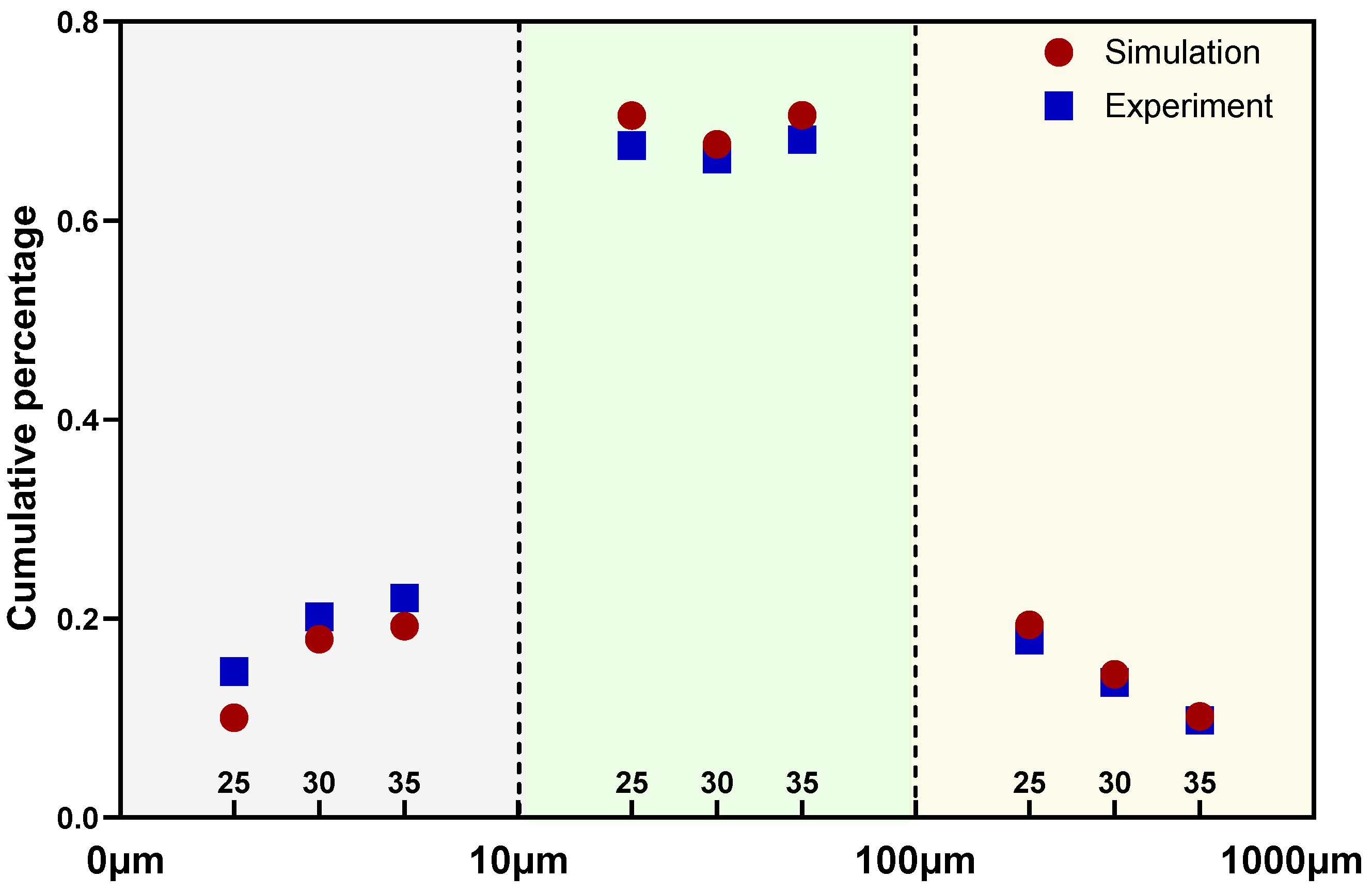
Droplet size was measured using a Malvern particle size analyzer (Figure 7a), with the nozzle axis perpendicular to the laser plane. Measurements were taken at axial distances of 25, 30, and 35 mm downstream of the nozzle, reflecting the spray gun’s operational range. Three replicate measurements per location were averaged. Particles were categorized into size intervals (0–101 μm, 10–102 μm, 102–103 μm) for cumulative distribution analysis.
As depicted in Figure 8, simulation results agree well with experimental data across most size intervals and axial distances. A notable discrepancy occurs in the 0–10 μm range, where simulations underpredict cumulative fractions. This is attributed to the exclusion of droplets below 10−16 m3 (equivalent to diameters < 10 μm) in the numerical model. Overall deviations remain within acceptable limits, confirming model robustness.
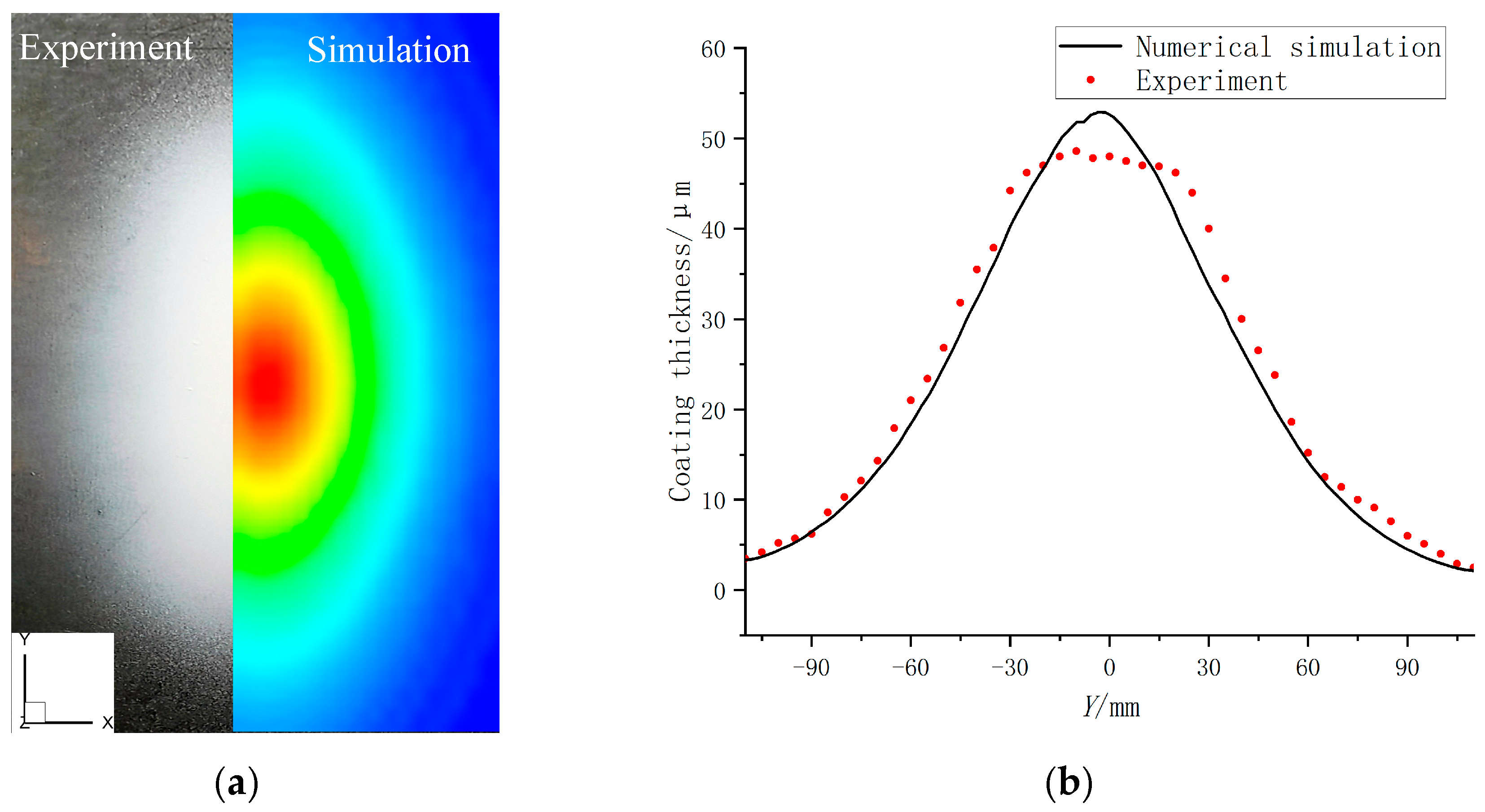
Film formation was simulated using atomization results as boundary conditions, with experimental validation under identical environmental/spray parameters (Figure 7b). Static spraying was employed (nozzle perpendicular to substrate, spray distance: 180 mm, duration: 1.0 s). After drying, coating thickness along the major axis (Y-direction) of the elliptical film was measured at 0.5 cm intervals using a thickness gauge. Three measurements per point were averaged; values were halved to represent 0.5 s spraying time. Comparison of coating thickness between numerical simulation and experimental simulation is shown in Figure 9.
Figure 9 demonstrates good agreement between the numerical simulations and experimental measurements for both coating morphology and thickness distribution along the major axis (Y direction). A minor deviation is observed wherein the experimental coating exhibits a slightly lower central thickness and marginally higher, uneven edge thickness compared to the simulation predictions. This discrepancy is primarily attributed to two factors: (1) post-deposition flow driven by gravity and surface tension [22,23] during the drying and solidification of the wet coating, leading to material redistribution away from the center; and (2) practical variations such as slight off-center positioning of the spray needle within the atomizing cap, resulting in asymmetric paint distribution during application. Nevertheless, the overall consistency validates the numerical model’s capability to predict coating formation.
The consistency in droplet size distributions and coating thickness profiles between simulations and experiments validates the numerical model for paint atomization.

3. Results and Discussion

3.1. Characteristics of the Gas-Phase Flow Field

Based on the established numerical model for the near-nozzle atomization process and the corresponding experimental platform, this subsection primarily analyzes the expansion process and velocity distribution characteristics of the gas phase in the air-assisted spraying flow field.

3.1.1. Gas-Phase Expansion Process

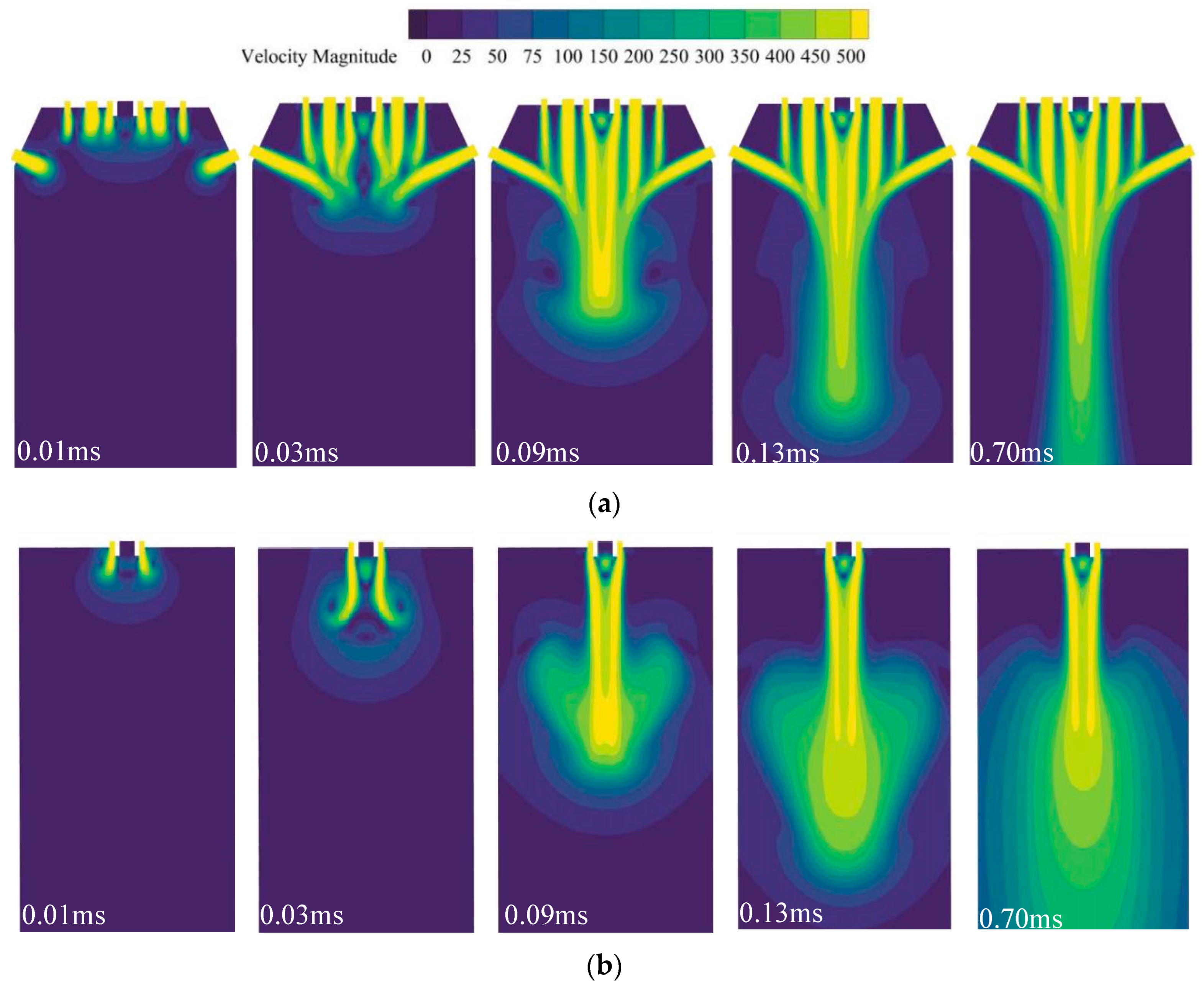
Numerical simulations reveal gas-phase flow stabilization at 0.7 ms. Figure 10 illustrates velocity contours at five timepoints (0.01 ms, 0.03 ms, 0.09 ms, 0.13 ms, and 0.70 ms), capturing flow development. The units for all velocity-related legends in the figures below are m/s.
In the XOZ plane (Figure 10a), the central and auxiliary air jets exhibit an inward inclination toward the inner auxiliary flow downstream, attributed to jet entrainment reducing pressure between adjacent streams. This pressure differential drives wake flow convergence toward the central axis. By 0.09 ms, fan-shaped control air merges with the central airflow under its influence, narrowing the main flow region and recovering a linear potential core aligned with the central axis. These interactions demonstrate the dominant role of central atomizing air in axial momentum, while fan-shaped and auxiliary flows collectively constrain radial expansion along the X-axis.
The YOZ plane (Figure 10b) shows a symmetric distribution about the central axis. Initial jet emergence (0.01 ms) displays only central airflow due to X-oriented orifice distribution. Subsequent mixing (0.03 ms) induces flow expansion and outward curvature of the central jet tail. Further development transforms the morphology from mushroom-like to ellipsoidal, covering the YOZ plane. This results from fan-shaped air compressing the main flow along X, enhancing its radial diffusion along Y.

3.1.2. Velocity Distribution of the Gas-Phase Flow Field

To deeply analyze and uncover the characteristics and mechanisms of the air-phase velocity distribution within the flow field, the gas-phase velocity is vectorially decomposed into axial velocity, which aligns with the Z-axis, and radial velocity, which is perpendicular to the Z-axis.
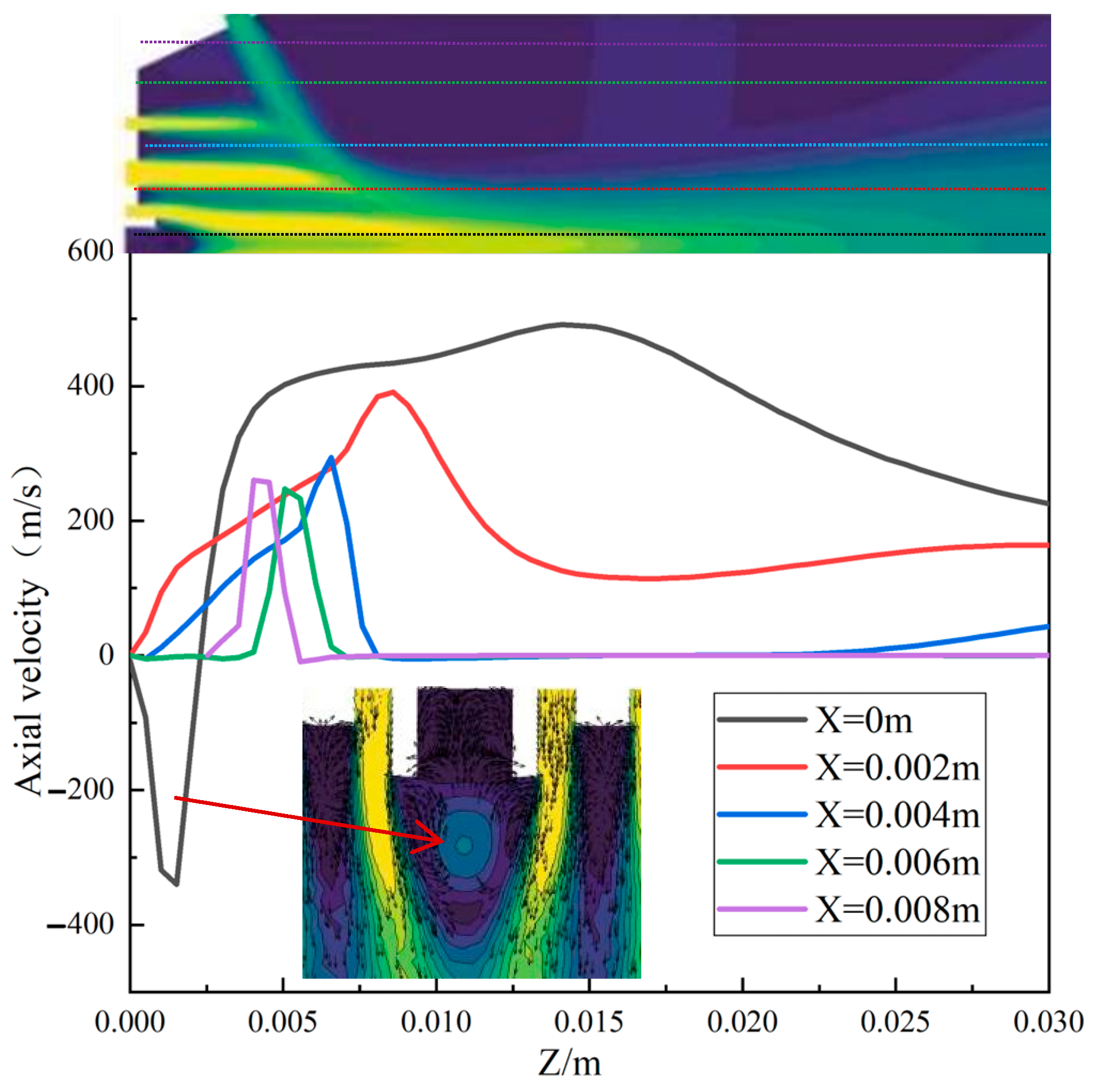
Given the structural features of the atomizing cap, such as the linear distribution of the gas–liquid outlets and short-axis symmetry, it is evident that the gas-phase velocity contour plot in the XOZ plane can comprehensively represent the interaction processes of various airflows. Therefore, the analysis focuses solely on the velocity distribution of the gas-phase flow field in the positive X-axis region of the XOZ plane. Figure 11 illustrates the axial velocity distribution curves of the gas phase at varying X coordinates, with each curve corresponding to the axial velocity conditions at different positions in the contour plot above.
It can be observed that there is a significant radial variation in the axial velocity of the gas phase, which means it initially increases and then decreases with an increase in axial distance (Figure 11). The maximum axial velocity of the gas phase in the flow field can reach 500 m/s; however, at the central axis (X = 0), the axial velocity of the gas phase becomes negative. Upon enlarging the contour of this region, vortices can be observed near the nozzle. The reason is that the single jet and the resulting mixed jet after intersection entrain the surrounding air, causing various degrees of negative axial velocities in the adjacent space. After the air jet entrains the surrounding static air, its velocity decreases. Therefore, as the axial distance increases, the axial velocity of the gas phase decreases.
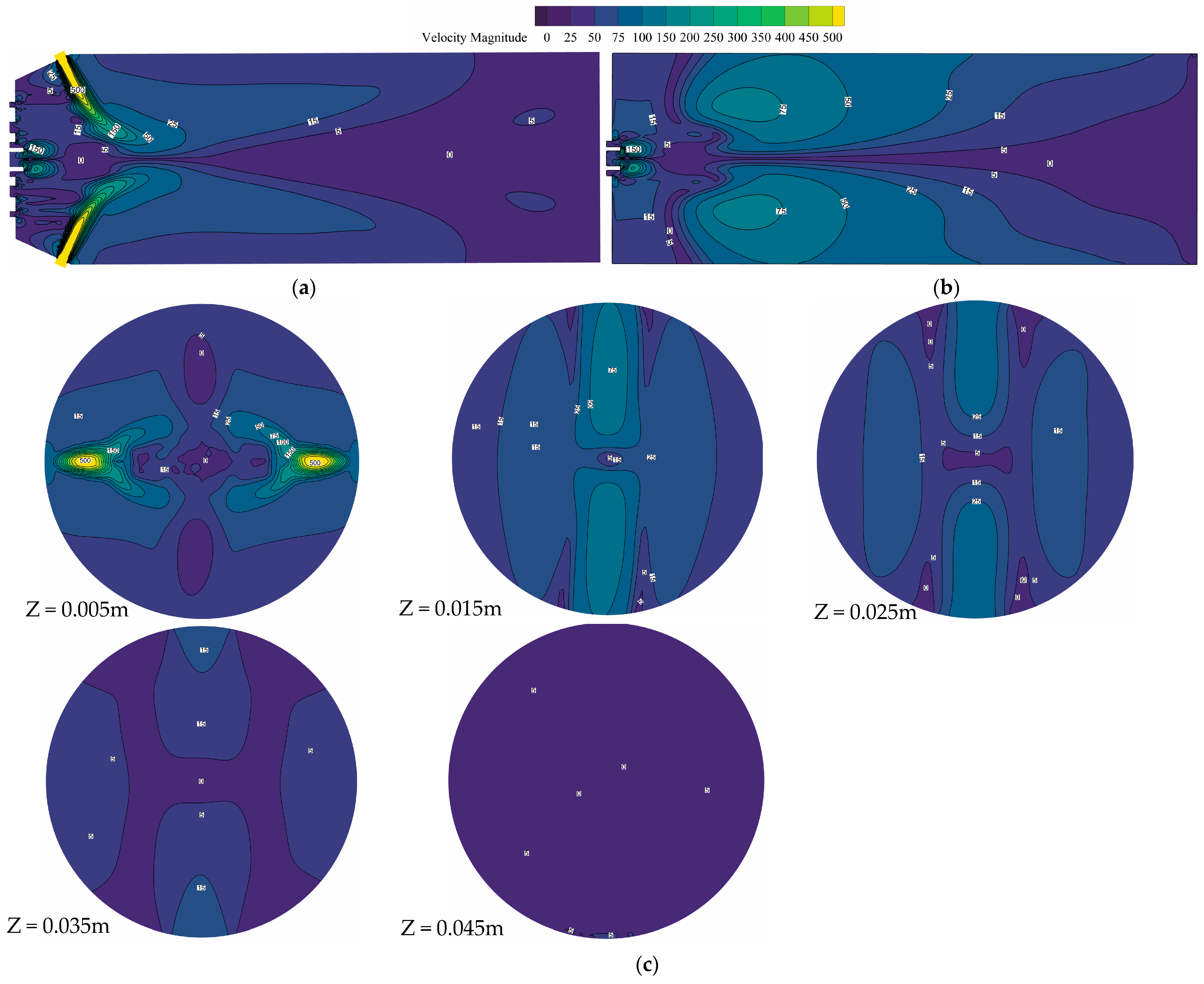
The radial velocity of the gas phase reflects the expansion velocity of the flow field in the XY direction, indirectly influencing the spray’s expansion range. Thus, investigating the distribution characteristics of the gas-phase radial velocity is of great significance for controlling the spray pattern. Figure 12 shows the radial velocity distribution in the XOZ plane of the gas-phase flow field, with a maximum radial velocity of 595 m/s and a minimum of 0 m/s. The radial velocity here is calculated as the arithmetic square root of the sum of the squares of the velocities in the X and Y directions, which can be expressed as
V x y = V x 2 + V y 2
where Vxy represents the radial velocity of the gas phase, Vx represents the gas phase velocity in the X direction, and Vy represents the gas phase velocity in the Y direction.
As illustrated in Figure 12a, the radial momentum in the flow field primarily originates from the fan-shaped air jet and the transverse motion generated by the entrainment effect of the central atomizing air flow at the paint nozzle. The overall radial velocity distribution of the gas-phase flow field is basically symmetrical about the central axis. The velocity is higher (above 50 m/s) along the expansion path of the fan-shaped airflow, while the majority of the remaining areas are low-velocity regions (below 15 m/s).
Figure 12b shows similar distribution characteristics to the distribution in the XOZ plane, and also exhibits a symmetrical pattern about the central axis. The maximum radial velocity is 158 m/s, but the minimum approaches 0 m/s. From the Y direction, the radial velocity increases as the distance from the central axis increases. From the Z direction, the velocities in the regions above the waist on both sides of the central axis are below 15 m/s, with a bulge in the contour lines indicating a maximum radial velocity at the waist. As the axial distance increases, the low-velocity region around the central axis expands.
As shown in Figure 12c, the radial velocity distribution on the XOY plane undergoes significant changes with increasing axial distance. The previously high-speed regions at both ends of the X-axis disappear, transitioning into symmetrical low-velocity zones (below 15 m/s). Simultaneously, the radial velocity at the Y-axis extremities increases from 0 m/s to approximately 75 m/s, while the central region exhibits a moderate increase from 0 m/s to 5–15 m/s. This evolution aligns with the phenomenon observed in the YOZ plane (Figure 12b), where maximum radial velocities emerge at the flow field waist.

3.2. Characteristics of the Spray Flow Field

The spray flow field refers to the atomized flow field formed by the interaction of gas and liquid phases under conditions of paint loading. This subsection primarily analyzes the spatial distribution characteristics of the paint phase, the velocity distribution characteristics of the spray flow field, and the distribution characteristics of paint particles within the spray flow field.

3.2.1. Spatial Distribution of the Paint Phase

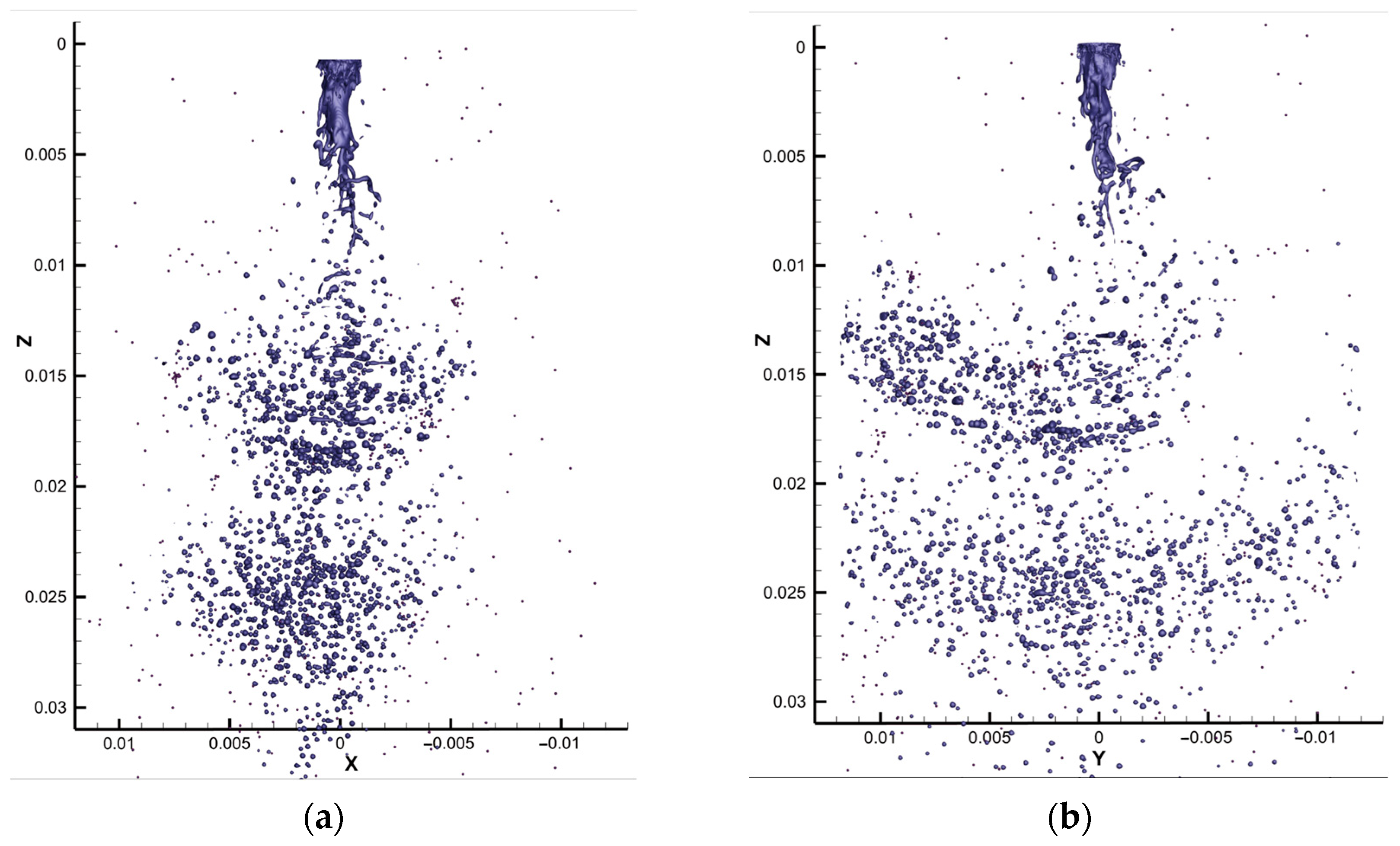
The spatial distribution of the paint phase is the key focus in atomization research, for it reflects the atomized spray morphology of the paint and directly relates to the spray coverage area, which is crucial for the quality of the spray-formed film. By extracting paint distribution data from stable atomized flow fields in the XOZ and YOZ planes and enlarging the atomized flow field within 30 mm of the nozzle, contours of paint volume fraction were obtained, as shown in Figure 13.
Under the set spraying parameters, the spray flow field exists as a mixture of air and droplets. Large droplets are mainly distributed in the central axis region close to the nozzle, while small droplets are widely distributed in areas farther from the nozzle. The spray distribution in the XOZ plane is relatively compact, whereas in the YOZ plane, it is more dispersed. The overall shape of the spray in both planes is fan-shaped, with spray cone angles of approximately 61.7° and 99.1°, respectively. The breakup length of the paint column is 8.1 mm.

3.2.2. Axial Velocity Distribution

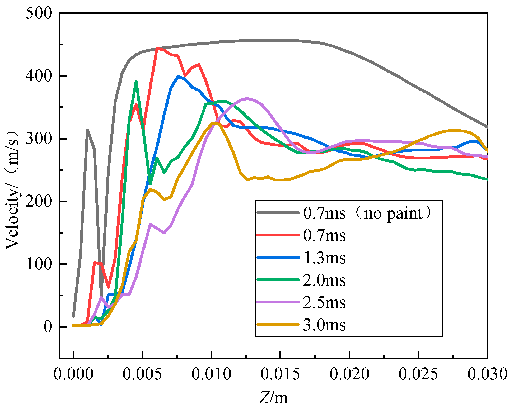
Aimed at five atomization moments of 0.7 ms, 1.3 ms, 2.0 ms, 2.5 ms, and 3.0 ms, the spray velocities along the central axis in both the steady-state gas-phase flow field and the spray flow field were exported. Through a quantitative analysis by comparing the velocity distributions in the flow field with and without paint loading, the velocity distribution in the spray flow field was examined, as shown in Figure 14.
In the single gas-phase flow field, the flow field velocity has reached a steady state at the atomization moment of 0.7 ms (Figure 14). However, after loading with paint, the atomization stabilization time is delayed until after 2.5 ms. This is related to the fact that the paint atomization process involves gas–liquid two-phase turbulent motion. As the atomization time increases, the velocities at various points along the central axis in the spray flow field decrease. This is primarily due to the continuous entry of low-velocity paint liquid into the flow field, which undergoes momentum exchange with the high-velocity gas, resulting in a significant reduction in the gas-phase velocity when paint is loaded compared to the gas-phase flow field without paint. Before the spray flow field stabilizes, the position of the maximum velocity along the central axis continuously shifts downstream as the atomization time progresses, and the maximum velocity value decreases.

3.2.3. Spray Particle Size Distribution

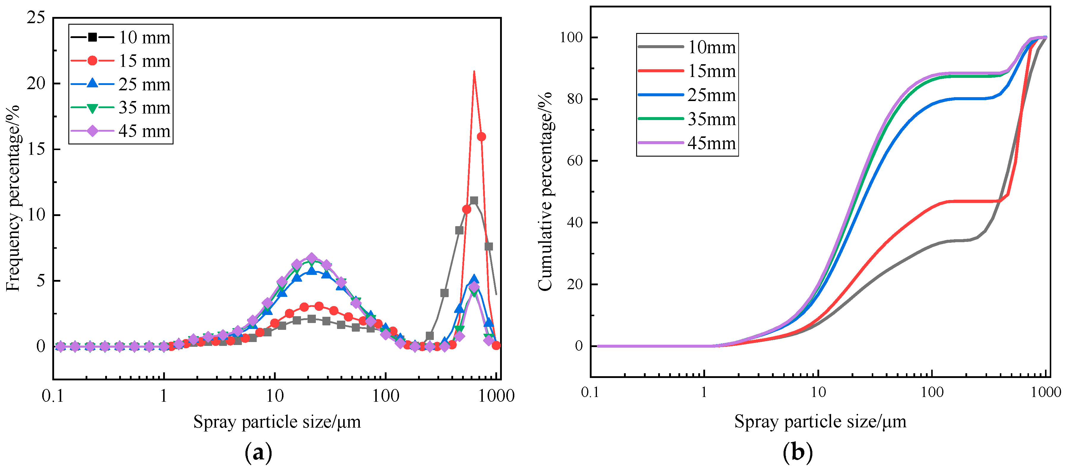
Some XY planes at axial distances of 10 mm, 15 mm, 25 mm, 35 mm, and 45 mm, respectively, were selected to analyze the particle size distribution, as shown in Figure 15.
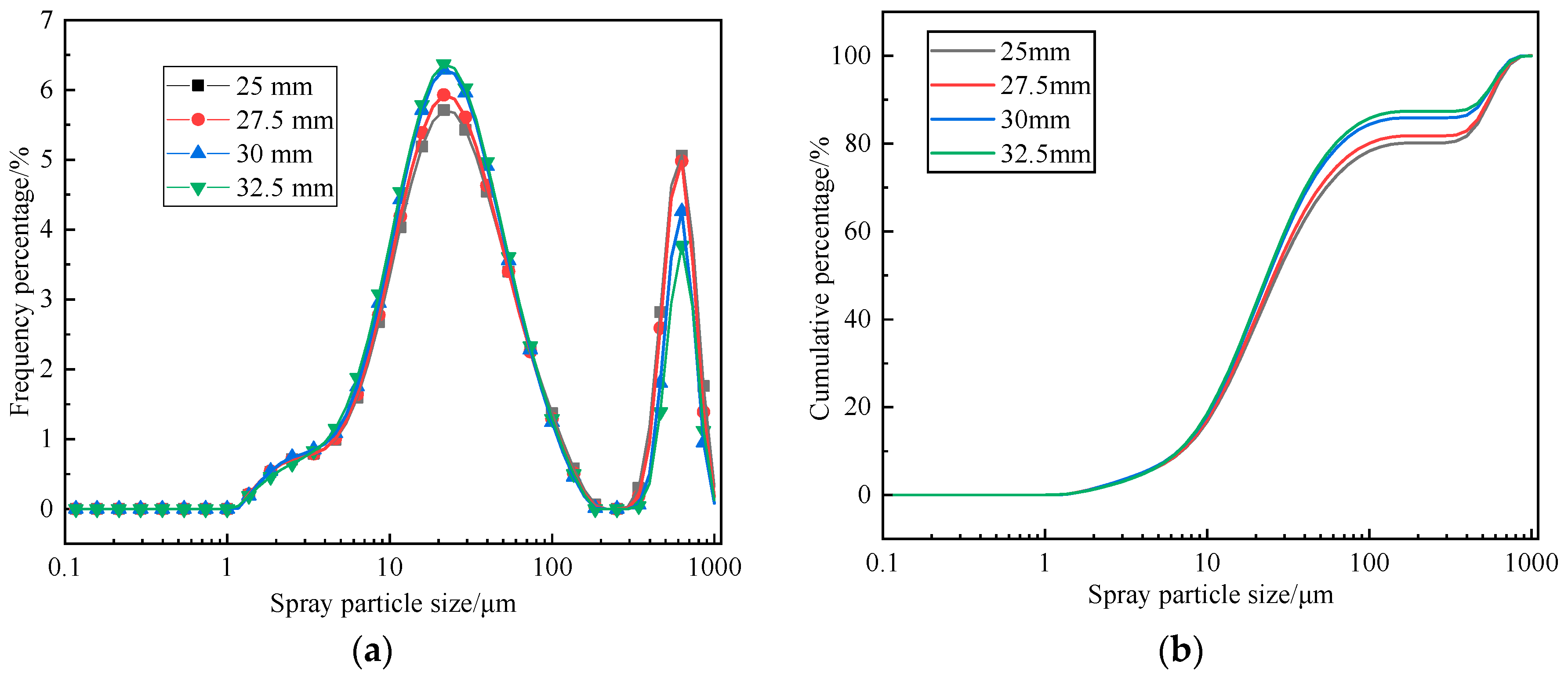
It can be observed that the spray particle size distribution on the planes within the axial distance range of 10 to 45 mm exhibits a bimodal distribution, primarily concentrated in the ranges of 10–100 μm and 450–850 μm (Figure 15). As the axial distance increases, the range of spray particle sizes gradually narrows, with the particle sizes decreasing. The frequency fraction of particles in the range of 0–100 μm continuously increases, which aligns with experimental measurements of spray particle sizes in regions far from the nozzle. Therefore, from the perspective of particle size distribution fluctuations, the spray particle size at an axial distance of 35 mm has stabilized. Based on the maximum spraying efficiency in air-assisted spraying processes [21], it is considered that when the proportion of spray particles in the range of 0–100 μm reaches 80% in a cross-section of the atomization flow field, the downstream region of that section has been fully atomized. To determine the fully atomized range, a detailed analysis was conducted on the region with an axial distance less than 35 mm. Data were collected at intervals of 2.5 mm from 25 mm to 32.5 mm from the nozzle, resulting in four sets of data. The spray particle size distribution curves are shown in Figure 16.
As shown in Figure 16 above, when the axial distance reaches 27.5 mm, the cumulative fraction of spray particles in the range of 0–100 μm is 80.13%. Therefore, it is concluded that the spray is fully atomized at this axial distance.

3.3. Discussion

This study provides the first integrated VOF-DPM characterization of near-nozzle atomization dynamics in air-assisted spraying, revealing previously unresolved mechanisms such as dual-origin radial momentum (Section 3.1.2) and surface tension-mediated ligament breakup (Section 3.2.1). The quantitative thresholds established—including flow stabilization distance (≤30 mm), atomization efficiency (80% droplets ≤ 100 μm at 27.5 mm), and temporal delays in gas–liquid stabilization (2.5 ms vs. 0.7 ms gas only)—offer actionable guidelines for optimizing coating uniformity on complex surfaces. Specifically, the identified synergy between auxiliary/fan airflows in constraining dispersion (Section 3.1.1) enables targeted parameter control to minimize overspray in industrial applications.
While this work elucidates fundamental gas–liquid interactions, three limitations warrant acknowledgment:
(1)
Nozzle Geometry Specificity: Simulations employed a single nozzle configuration (W-71). Generalizability to divergent architectures requires validation. Future studies should parameterize orifice geometry (diameter, orientation) to establish scaling laws.
(2)
Newtonian Fluid Assumption: Paint was modeled as an incompressible Newtonian fluid (Section 2.1), neglecting shear-thinning/thickening behaviors common in industrial coatings.
(3)
Parametric Range: Experiments/simulations used fixed operational parameters (e.g., 2.6 atm air pressure, 0.00495 kg/s paint flow). Comprehensive parameter–space exploration is needed to build predictive control models.
These limitations, however, do not compromise the mechanistic insights or methodological advances achieved. Instead, they define clear pathways for extending this research—particularly in developing adaptive nozzle systems for complex-surface coating.

4. Conclusions

In this paper, three-dimensional numerical simulations validated by experimental measurements were employed to elucidate paint atomization dynamics in air-assisted spraying, particularly within the near-nozzle region. Key findings are summarized as follows:
  • Numerical results demonstrate that initial paint atomization occurs at 2.5 ms under the synergistic action of high-speed air jets from the central, auxiliary, and fan-shaped orifices. The spray flow field stabilizes within 30 mm downstream of the nozzle. In this near-field region, atomization yields a mixture of fine droplets and larger discontinuous ligaments/droplets, with droplet density highest along the central axis and decreasing radially.
  • Radial momentum predominantly originates from the fan-shaped air jets and transverse motion induced by central air jet entrainment at the paint inlet, exhibiting higher magnitudes along fan-air expansion paths. Axial momentum is primarily governed by the central atomizing air, displaying a characteristic increase followed by a decrease with axial distance. Both auxiliary and fan-shaped flows constrain transverse airflow expansion.
  • Prior to stabilization (post-2.5 ms), the position of maximum velocity along the central axis migrates downstream while its magnitude decreases. The spray comprises air-droplet mixtures, with large droplets concentrated near the central axis close to the nozzle and smaller droplets dispersed peripherally. Measured spray cone angles are 61.7° (short axis) and 99.1° (long axis), with a paint column breakup length of 8.1 mm. Full atomization (≥80% droplets ≤ 100 μm) is achieved at 27.5 mm from the nozzle.
This study focused on characterizing the fundamental atomization flow field. Future work should investigate the influence of key spray parameters (e.g., air pressures, paint properties, nozzle geometry) on atomization efficiency and droplet distribution to optimize coating quality.

Author Contributions

Conceptualization, Y.C. and J.D.; methodology, S.C.; software, Z.W.; validation, S.C. and G.F.; formal analysis, Y.Z.; investigation, Z.W.; resources, Y.Z.; data curation, S.C.; writing—original draft preparation, S.C.; writing—review and editing, S.C.; visualization, Y.Z.; supervision, Y.C. and J.D.; project administration, Y.C. and J.D.; funding acquisition, S.C., Y.C. and J.D. All authors have read and agreed to the published version of the manuscript.

Funding

This project is supported by the Natural Science Foundation of China (52302422 and 52272338), the Natural Science Foundation of Chongqing, China (CSTB2024NSCQ-QCXMX0080 and CSTB2024NSCQ-MSX1039), the Science and Technology Research Program of Chongqing Municipal Education Commission (grant No. KJQN202412903 and KJZD-M202312901).

Institutional Review Board Statement

Not applicable.

Informed Consent Statement

Not applicable.

Data Availability Statement

The original contributions presented in this study are included in the article. Further inquiries can be directed to the corresponding authors.

Conflicts of Interest

The authors declare no conflicts of interest.

References

  1. Zhao, K.; Ding, Y. Investigation of dynamic characteristics of liquid nitrogen droplet impact on solid surface. Sustainability 2022, 14, 710. [Google Scholar] [CrossRef]
  2. Zhao, J.S.; Wei, S.T.; Zhao, D.J.; Yao, Y.B.; Wang, L.P.; Guo, L.J. Research Advancement of Coating Robot for Super Large Space. Aeronaut. Manuf. Technol. 2023, 66, 46–58. [Google Scholar]
  3. Wittmann, A.; Wronski, T.; Shafirovich, E.; Schönnenbeck, C.; Brillard, A.; Brilhac, J.-F.; Tschamber, V. Oxidation of magnesium particles in a fluidized bed reactor. Combust. Flame 2025, 272, 113853. [Google Scholar] [CrossRef]
  4. Wang, Y.; Zhang, M.L.; Wang, Y.; Wen, K.; Zhuo, K.; Guo, R.; Gao, P. Partially Coherent Illumination-based digital holographic microscopy and its applications. Laser Optoelectron 2021, 58, 1811005. [Google Scholar]
  5. Han, Y.C.; Bowen, D.J.; Barreto, B.L.; Zwaan, R.R.; Strachinaru, M.; van der Geest, R.J.; Hirsch, A.; van den Bosch, A.E.; Bosch, J.G.; Voorneveld, J. Validation of left ventricular high frame rate echo-particle image velocimetry against 4d flow mri in patients. Ultrasound Med. Biol. 2025, 51, 94–101. [Google Scholar] [CrossRef]
  6. Cholemari, M.R.; Vishnubhatla, S.H. Analysis of an accurate iterative technique with attenuation compensation in planar laser induced fluorescence. Meas. Sci. Technol. 2025, 36, 015301. [Google Scholar] [CrossRef]
  7. Domnick, J.; Thieme, M. Atomization characteristics of high-speed rotary bell atomizers. At. Sprays 2006, 16, 857–874. [Google Scholar] [CrossRef]
  8. Liu, Z.Y.; Yu, Q.B.; Ma, W.D.; Liu, J.; Tao, S. Experimental investigation on centrifugal granulation of molten yellow phosphorus slag. Chem. Eng. Res. Des. 2023, 197, 548–557. [Google Scholar] [CrossRef]
  9. Benmoussa, A.; Pendar, M.R.; Páscoa, J.C. Enhancing electrostatic spray-painting efficiency with modified high-voltage conductors: A numerical study on pulsed electric fields. J. Aerosol Sci. 2024, 184, 106491. [Google Scholar] [CrossRef]
  10. Domnick, J.; Scheibe, A.; Ye, Q. The simulation of the electrostatic spray painting process with high-speed rotary bell atomizers. Part I: Direct charging. Part. Part. Syst. Charact. 2005, 22, 141–150. [Google Scholar] [CrossRef]
  11. Maly, M.; Slama, J.; Sapik, M.; Jedelsky, J.; Dančová, P.; Novosad, J. 2D and 3D numerical modelling of internal flow of pressure-swirl atomizer. In Proceedings of the 13th International Conference “Experimental Fluid Mechanics 2018”, Prague, Czech Republic, 13–16 November 2018; EDP Sciences: Les Ulis, France, 2019; Volume 213, p. 02055. [Google Scholar]
  12. Xiang, Y. Simulation of centrifugal nozzle atomization based on LES. Mod. Manuf. Technol. Equip. 2018, 12, 104–105. [Google Scholar]
  13. Fogliati, M.; Fontana, D.; Garbero, M.; Vanni, M.; Baldi, G.; Dondè, R. CFD simulation of paint deposition in an air spray process. J. Coat. Technol. Res. 2006, 3, 117–125. [Google Scholar] [CrossRef]
  14. Wang, Y.A.; Xie, X.P.; Lu, X.H. Design of a double-nozzle air spray gun and numerical research in the interference spray flow field. Coatings 2020, 10, 475. [Google Scholar] [CrossRef]
  15. Ye, Q.; Shen, B.; Tiedje, O.; Bauernhansl, T.; Domnick, J. Numerical and experimental study of spray coating using air-assisted high pressure atomizers. At. Sprays 2015, 25, 643–656. [Google Scholar] [CrossRef][Green Version]
  16. Ye, Q.; Domnick, J. Analysis of droplet impingement of different atomizers used in spray coating processes. J. Coat. Technol. Res. 2017, 14, 467–476. [Google Scholar] [CrossRef]
  17. Wu, Z.J.; Chen, Y.; Liu, H.S.; Hua, W.; Duan, J.; Kong, L. A review of the developments of the characteristics and mechanisms of airless spraying on complex surfaces. Coatings 2023, 13, 2095. [Google Scholar] [CrossRef]
  18. Yu, S.H.; Yin, B.F.; Deng, W.X.; Jia, H.; Ye, Z.; Xu, B.; Xu, H. Numerical investigation on effects of elliptical diesel nozzle on primary spray characteristics by large eddy simulation (LES). At. Sprays 2018, 28, 695–712. [Google Scholar] [CrossRef]
  19. Chen, Y.; Chen, S.M.; Chen, W.Z.; Hu, J.; Jiang, J. An atomization model of air spraying using the volume-of-fluid method and large eddy simulation. Coatings 2021, 11, 1400. [Google Scholar] [CrossRef]
  20. Ali, F.; Narasimhamurthy, S.; Hegde, S.; Usman, M. Temperature-dependent viscosity analysis of powell-eyring fluid model during a roll-over web coating process. Polymers 2024, 16, 1723. [Google Scholar] [CrossRef]
  21. Liu, H.T.; Ou, M.X.; Dong, X.; Zhou, W.; Dai, S.; Jia, W. Spraying performance and deposition characteristics of an improved air-assisted nozzle with induction charging. Front. Plant Sci. 2024, 15, 1309088. [Google Scholar] [CrossRef] [PubMed]
  22. Li, M.; Yang, H.Z.; Wang, J.J.; Li, G.; Tang, J. An Experimental Investigation of the Impact of Surface Tension and Viscosity on the Atomization Effect of a Solid Cone Nozzle. Appl. Sci. 2023, 13, 4522. [Google Scholar] [CrossRef]
  23. Chideme, N.; de Vaal, P. Effect of Liquid Viscosity and Surface Tension on the Spray Droplet Size and the Measurement Thereof. J. Appl. Fluid Mech. 2024, 17, 2652–2672. [Google Scholar]
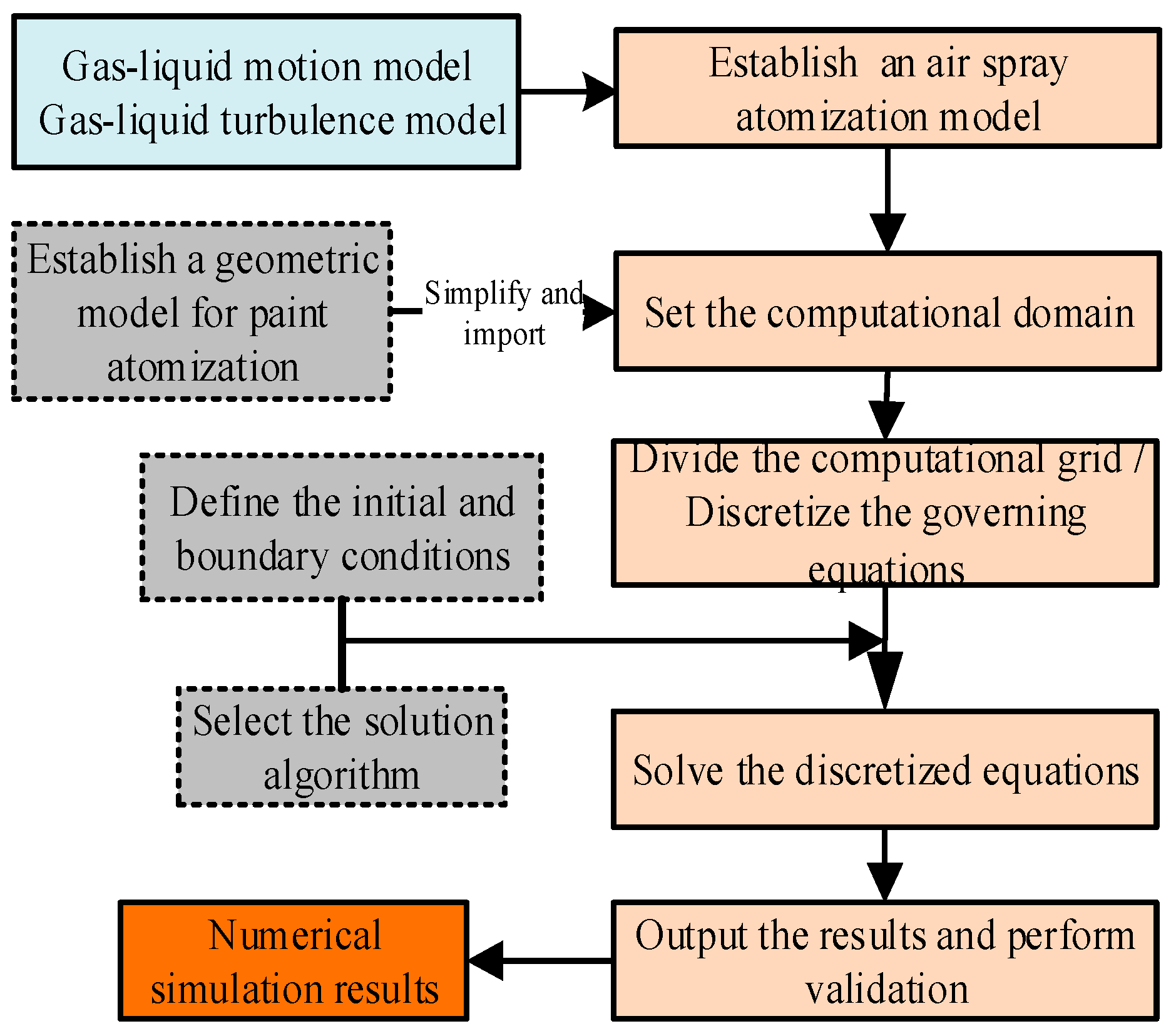
Figure 1. Overall process diagram of the present simulation study.
Coatings 15 00939 g001
Figure 2. The atomizing cap of an air-assisted spraying gun.
Coatings 15 00939 g002
Figure 3. Computational domain.
Coatings 15 00939 g003
Figure 4. Across-section view of the computational domain grid.
Coatings 15 00939 g004
Figure 5. Iterative residual graph for numerical calculation.
Coatings 15 00939 g005
Figure 6. Numerical simulation results of paint atomization.
Coatings 15 00939 g006
Figure 7. Experimental platforms. (a) The system for measuring the particle size. (b) The system for measuring the coating thickness.
Coatings 15 00939 g007
Figure 8. Comparison of cumulative fractions of different particle sizes at different axial distances between numerical simulation and experiment.
Coatings 15 00939 g008
Figure 9. Comparison of coating thickness between numerical simulation and experimental simulation. (a) Coating morphology. (b) Coating thickness.
Coatings 15 00939 g009
Figure 10. Gas-phase flow field morphology. (a) Plane XOZ. (b) Plane YOZ.
Coatings 15 00939 g010
Figure 11. Gas-phase axial velocity distribution at varying X coordinates.
Coatings 15 00939 g011
Figure 12. Gas-phase radial velocity distributions. (a) Plane XOZ. (b) Plane YOZ. (c) Plane XOY.
Coatings 15 00939 g012
Figure 13. Spatial distribution of paint phase. (a) Plane XOZ. (b) Plane YOZ.
Coatings 15 00939 g013
Figure 14. Velocity distribution in the center axis of spray flow field.
Coatings 15 00939 g014
Figure 15. Spray flow field particle size is distributed under mm. (a) Particle size frequency distribution. (b) Cumulative distribution of particle size.
Coatings 15 00939 g015
Figure 16. Spray particle size distribution at different positions within the axial distance of 25~32.5 mm. (a) Frequency distribution. (b) Cumulative distribution.
Coatings 15 00939 g016
Table 1. Partial boundary conditions.
Gas-Phase InletsPressure Inlet (2.6 atm Total Pressure) for All Air Orifices
Liquid-phase inletMass flow inlet (0.00495 kg/s) for the paint nozzle
Ambient pressure1 atm (operating pressure)
Gravity−9.8 m/s2 in the Z-direction
Disclaimer/Publisher’s Note: The statements, opinions and data contained in all publications are solely those of the individual author(s) and contributor(s) and not of MDPI and/or the editor(s). MDPI and/or the editor(s) disclaim responsibility for any injury to people or property resulting from any ideas, methods, instructions or products referred to in the content.