1. Introduction
DLC coatings have been extensively investigated in recent years due to their promising potential in tribological applications [
1,
2]. Owing to their high hardness and low friction coefficients [
3], which are primarily attributed to the formation of stress-induced regions enriched in sp
2-bonded carbon [
4,
5]. These coatings are highly effective in enhancing the tribological performance of various materials.
DLC coatings can be deposited by Plasma-Assisted Chemical Vapor Deposition (PACVD) methods, which enable a significant reduction in the processing temperature compared to conventional coating techniques [
6,
7]. Carbon-based amorphous films produced on steel substrates under different CVD process variants have demonstrated a remarkable improvement in the tribological properties of the treated components [
5,
8,
9,
10]. These methods also allow precise control over the composition of the reactive atmosphere and the process parameters, both of which directly influence the microstructure of the deposited coatings and, consequently, their mechanical properties [
11] and internal stresses [
12]. Moreover, the use of glow discharge-assisted CVD enables the deposition of coatings on components with complex geometries, which are often encountered in tribological systems [
13]. One such method frequently used to produce DLC coatings is RFCVD.
One of the major limitations preventing the widespread application of carbon-based coatings is their relatively poor adhesion to metallic substrates. This drawback is mainly caused by the high internal stresses typically present in carbon films, as well as the formation of layers of oxides on certain metal surfaces [
14]. To improve adhesion, the chemical composition of DLC coatings is commonly modified by doping with various elements such as N, Si, Fe, W, Ti, or B [
15,
16,
17,
18,
19,
20]. Another widely applied strategy involves the use of interlayers containing elements that readily form carbides [
3], including chromium [
1,
20,
21], titanium and its compounds [
22], as well as silicon [
20,
23,
24,
25] and its compounds [
26]. Further enhancement in adhesion between carbon coatings and steel substrates can be achieved by modifying the surface layer of the substrate through thermochemical treatments such as nitriding [
8], carbonitriding [
16,
27,
28,
29,
30,
31], or carburizing [
32,
33]. Surface preparation prior to coating deposition also plays a crucial role in improving adhesion. This involves thorough cleaning to remove contaminants, pre-etching of the substrate using argon ion bombardment [
3,
34], and adjusting the surface roughness to ensure optimal mechanical interlocking [
35].
Unfortunately, some of the aforementioned methods for improving adhesion require the use of expensive equipment with additional sources of chemical elements, such as magnetron targets [
19], or involve the application of hazardous compounds [
18], which impose further technical and safety requirements on the deposition apparatus. Moreover, the production of interlayers introduces an additional processing step into the manufacturing cycle, which increases production costs and prolongs fabrication time. In addition, techniques based on diffusion-driven processes, such as nitriding, carburizing, and their derivatives, require elevating the temperature of the treated component beyond the stability threshold, which may lead to structural degradation in materials with limited thermodynamic stability [
36]. Similarly, certain interlayers can exhibit insufficient adhesion if deposited at an overly low temperature [
25].
Hydrogen and nitrogen are among the most commonly used and extensively studied doping elements for modifying the properties (adhesion, among others) of carbon-based coatings [
37,
38]. The principal advantage of both gases lies in their simple and safe application: they can be introduced directly into the reactive gas mixture as molecular nitrogen (N
2) and hydrogen (H
2), which are widely available, do not require advanced delivery systems, and pose no greater risk than the typical carbon precursors, such as CH
4 or C
2H
2, used in the production of carbon coatings. It is well established that by adjusting the hydrogen-to-carbon ratio in the reactive gas mixture during PACVD, one can modify the proportion of various chemical bonds in the deposited film [
3], which directly affects its tribological properties [
39]. An increase in hydrogen concentration up to a certain threshold promotes the formation of sp
3-bonded carbon, which in turn enhances the nanohardness and internal stresses of the coating [
3,
40]. However, at higher hydrogen concentrations, this trend can reverse, leading to an increased proportion of sp
2 bonds, and consequently, a reduction in both the hardness and internal stresses of the carbon coating [
39,
41]. On the one hand, lowering the nanohardness and stiffness of the coating may negatively affect its abrasive wear resistance, especially when applied to silicon-based substrates [
39]. On the other hand, the reduction in internal stresses is known to improve adhesion to metallic substrates [
14], which, in turn, enhances performance in tribological applications. Therefore, the influence of hydrogen on the final properties of carbon coatings is complex, depends on multiple factors, and must always be considered in the context of other process parameters and the specific type of substrate used.
The addition of nitrogen to carbon-based coatings typically leads to a reduction in the proportion of sp
3-bonded carbon [
42,
43], which in turn results in lower internal stresses [
44], but also a decrease in nanohardness [
45,
46]. Such a change decreases the difference in mechanical properties between metallic substrates and DLC coatings. Tribological studies have shown that nitrogen-doped carbon coatings exhibit improved adhesion, a more stable friction coefficient [
47], and a lower wear rate as the nitrogen content increases [
48]. At the same time, the introduction of nitrogen and hydrogen into the gas mixture reduces the overall carbon content, which negatively impacts the growth rate of the coating during glow discharge-assisted deposition processes [
38,
40].
Oxygen is another element commonly present in carbon coatings, although it is often regarded as a contaminant. The available literature on the effect of oxygen incorporated into the structure of amorphous carbon films is relatively limited. Nevertheless, there are reports suggesting that the presence of oxygen can contribute to increased coating hardness and promote a higher sp
3 bond fraction [
49], which consequently leads to elevated internal stresses within the film [
50]. In reactive magnetron sputtering processes, oxygen plasma has been reported to selectively remove sp
2-hybridized carbon not bonded to hydrogen, thus promoting the formation of sp
3 bonds [
51,
52]. Therefore, oxygen exhibits an effect opposite to that of nitrogen, and its presence in the film may also influence the final functional properties of the deposited coating.
Although numerous studies have investigated the influence of nitrogen and hydrogen on the microstructure and tribological performance of carbon-based coatings [
15,
39,
47,
48], the current state of knowledge lacks reports addressing the possibility of achieving sufficient adhesion to steel substrates solely through the controlled addition of such gaseous dopants. This is particularly relevant for applications involving ultra-fine bainitic steels, where conventional adhesion enhancement strategies—including interlayer deposition or high-temperature thermochemical surface treatments—are often incompatible due to their detrimental effect on the stability of the refined bainitic microstructure [
36,
53]. Therefore, the present study aims to evaluate whether the targeted modification of the reactive gas composition using readily available and relatively safe gases, such as hydrogen and nitrogen, during the RFCVD process allows for the fabrication of carbon coatings exhibiting adequate adhesion to surface-hardened steel substrates, while maintaining processing temperatures sufficiently low to preserve the structure of the ultra-fine bainitic core.
2. Materials and Methods
2.1. Material and Heat Treatment
The chemical composition of the 30HGSNA steel used as a substrate is presented in
Table 1, according to the PN-H-84035 standard [
54].
The test specimens, in the form of discs with a height of 20 mm, were cut from a bainitic 30HGSNA steel rod with a diameter of 165 mm. An ultra-fine bainitic microstructure was obtained via an isothermal hardening process consisting of austenitizing at 900 °C for 30 min, followed by cooling to 360 °C and holding at this temperature for 90 min. Surface hardening was carried out using a robotic laser processing station equipped with a 12 kW YAG disk laser (TruDisk 12002, Trumpf, Ditzingen, Germany), an industrial robot (KUKA KR30HA, Kuka, Augsburg, Germany), and a Trumpf PFO scanning optic head (Trumpf, Ditzingen, Germany) mounted on the robot’s wrist. The surface laser hardening of the samples was performed under the following parameters: P = 3500 W (laser power), f = 100 mm (defocusing distance, i.e., the distance between the sample surface and the focal plane of the laser beam), v = 0.5 m/min (linear scanning speed), vo = 1000 mm/s (oscillation speed), oscillation pattern: figure of eight, s = 1 mm (oscillation width), oscillation amplitude = 30 mm.
After laser hardening, the samples were sectioned, and their side surfaces were polished for microstructural analysis. On cross-sections of the hardened zones, Vickers microhardness (HV0.1) profiles were measured. Micrographies and hardness distributions were recorded at five measurement points to determine the depth of the hardened layer.
2.2. RFCVD
Subsequently, the hardened surfaces were further prepared by polishing the face side of the samples until achieving a mirror-like surface. Carbon coatings were then deposited via the RFCVD process using a Roth & Rau MicroSys 400 (Roth & Rau, Hohenstein-Ernstthal, Germany) system equipped with a radio frequency power source operating at 13.56 MHz. Before the deposition of the carbon coatings, the sample surfaces were plasma-cleaned for 5 min in an atmosphere composed of argon and hydrogen (4:1 ratio) at a discharge power of 600 W and a pressure of 1 × 10⁻² mbar.
During carbon deposition, the process parameters were kept constant: T = 30 min (deposition time), P = 600 W (discharge power), p = 1 × 10
−2 mbar (reaction atmosphere pressure). No additional heating was applied to the samples during deposition. The temperature increased naturally due to glow discharge heating, reaching approximately 80 °C from room temperature over the course of the process. These parameters were selected based on prior experimental studies to avoid degradation of the ultra-fine bainitic microstructure [
53]. A series of samples was prepared with varying nitrogen-to-methane-to-hydrogen volume ratios in the reactive atmosphere (all atmosphere compositions in this article are denoted in the following format and order: [nitrogen–methane–hydrogen]). The gas proportions were controlled based on the individual flow rates (expressed in sccm) and are listed in
Table 2.
Samples marked in red in the table underwent spontaneous delamination upon opening the chamber or failed upon first contact with the indenter during testing. In order to limit the number of tests and to increase the clarity of the presented work the samples marked in orange were included only in the assessment of basic mechanical properties of the coatings, while samples marked in green—as boundary cases, where the changes should be the most visible—were additionally subjected to chemical composition analysis, coating thickness measurements, and abrasive wear resistance tests.
2.3. Nanohardness
NanoTest Vantage (Micromaterials Ltd., Wrexham, UK) with a Berkovich diamond indenter was used to determine the nanohardness of the coatings. The parameters used during the nanohardness testing are listed in
Table 3.
2.4. Scratch Test
Adhesion tests were conducted using a CSM Revetest Scratch Tester (CSM Instruments, Needham, MA, USA). Three scratches, each 5 mm in length, were made on each sample, with a progressively increasing load ranging from 1 to 30 N. A Rockwell diamond cone with a tip rounding radius of 0.2 mm was used as the indenter. The resulting scratches were documented through photography using a Nikon Eclipse LV150N metallographic microscope (Nikon Metrology, Inc., Brighton, MI, USA). Based on the obtained images, the locations of the first damage and the complete delamination of the carbon layers were identified. The distances of these points from the beginning of the scratch were converted into the corresponding load values.
2.5. Raman Spectroscopy
Raman spectroscopy of carbon coatings was carried out using a JASCO NRS 5100 spectrometer (JASCO, Tokyo, Japan) equipped with a 532 nm VIS Ar
+ laser (2.33 eV). The laser beams were focused on the surface of the carbon coatings in areas of approximately 20 μm in diameter. The spectral registration parameters were selected to ensure maximum peak intensity without causing any damage to the sample surfaces. The recorded spectra were analyzed using JASCO peak processing software: Spectra Manager Micro Imaging Analysis v.2.3 (JASCO, Tokyo, Japan) and Curve Fitting v.1.9 (JASCO, Tokyo, Japan). During data processing, spectra were interpolated, and their background was subtracted to align intensity levels at the edges of the analyzed range. The curve fitting procedure involved determining peak parameters. The final values of intensity, position, full width at half maximum (FWHM), and peak shape (Gaussian, Lorentzian, or a mixed Gaussian–Lorentzian function) were optimized using the least-squares fitting method. The sp
3 bond content was assessed based on the G peak position method presented by Singha [
55]. According to this model, the sp
3/sp
2 ratio in hydrogenated DLC coatings can be estimated using the following expression:
where
is a G peak position expressed in an inverse micrometer unit.
2.6. XPS
The XPS measurements of carbon coatings were performed by means of the Microlab350 spectrometer (Thermo Electron) (Thermo Fisher Scientific, Waltham, MA, USA) using AlKα non-monochromatic radiation (1486.6 eV) as a source, with a maximum resolution of 0.83 eV. Ar
+ ion sputter etching with the beam energy of 2 keV was used for 60 s prior to XPS analyses to remove surface contaminants. Scan analyses were carried out with the measurement area of 5 × 2 mm and a pass energy of 100 eV and the energy step of 1 eV for survey spectra and 40 eV and 0.1 eV, respectively, for high-resolution (HR) spectra. An Avantage Surface Chemical Analysis software (ThermoFisher Scientific, ver. 5.41, Waltham, MA, USA) was used for the XPS data analysis. Deconvolution of the HR spectra was performed with a smart-type background and a Gaussian peak shape with a 30% Lorentzian character. The binding energies (BE) of all detected elements were corrected with respect to the BE of the C 1s peak at 284.3 eV (C-C sp
2 bond). [
56].
2.7. SEM
The samples were initially cut using an electrical discharge cutting machine, after which the cut surfaces were polished. Subsequently, a Focused Ion Beam (FIB) cut was performed using an argon ion beam with a Hitachi IM4000 system (Hitachi, Tokyo, Japan). This technique enables the preparation of cross-sections without the need for mechanical grinding, thereby preserving the structural integrity of the sample surface. This preparation method allowed for high-resolution microscopic observations of the coating cross-sections using scanning electron microscopes (SEM), Hitachi SU-8000 (Hitachi, Tokyo, Japan) and JEOL 7600F (JEOL, Tokyo, Japan). The application of FIB also prevented coating chipping, which is often encountered with conventional cutting techniques of such coatings. Due to the poor conductivity of the carbon coating, a thin metallic layer has been deposited onto the sample, which can be visible in the photographs.
2.8. Ball-on-Disc Tests
In order to better replicate the surface condition of real-world technical components, samples destined for tribological wear testing were pre-ground using 800-grit abrasive paper and etched by immersion in a 5% nital solution for one minute prior to coating deposition. After this preparation step, the samples were processed according to the parameters described above.
Wear resistance was evaluated using a “ball-on-disc” test setup on a T-21 tester (Institute for Sustainable Technologies, Radom, Poland). Tests were performed under a normal load of 5 N for a total of 2500 cycles of 8mm in diameter, at a rotation speed of 145 rpm. The counter-body was a 6 mm diameter Al
2O
3 ceramic ball. Fiction coefficient was recorded at a frequency of 2 Hz. The measurement data were smoothed using a moving average of five adjacent values to minimize oscillation-induced noise from the measurement system. The chosen test parameters ensured highly aggressive contact conditions for the tribological pair, allowing the observation of the entire wear process: initial operation with the intact coating, progressive degradation of the carbon layer, and eventual direct steel-to-ball contact after coating failure. This approach enabled the accelerated assessment of the full-service life of the coatings, providing practical insights into their functional performance. The wear tracks were documented using a Nikon Eclipse LV150N metallographic optical microscope (Nikon Metrology, Inc., Brighton, MI, USA) producing detailed photographs of specific regions of interest. The analysis of surface roughness was carried out using a WYKO NT9300 optical profilometer (Veeco, Plainview, NY, USA), with a 10× magnification. Each sample underwent five separate groove cross-section area measurements, allowing for the determination of the average values of V (see Equation (2)) using the Vision ver. 4.10 software. To evaluate frictional wear resistance, the dimensions of the wear track formed by the “ball-on-disc” method were assessed. The geometry of the wear groove was measured at four points along its circumference (spaced at 90° intervals) using a Veeco optical profilometer. The cross-sectional area of the groove was then computed with the Vision
R software. Additionally, the wear index was determined based on the following Equation:
where: V—worn material volume calculated on the basis of the average size of the groove’s cross-sectional area; F
n—axial force; s—friction track length.
3. Results
3.1. Laser-Hardening
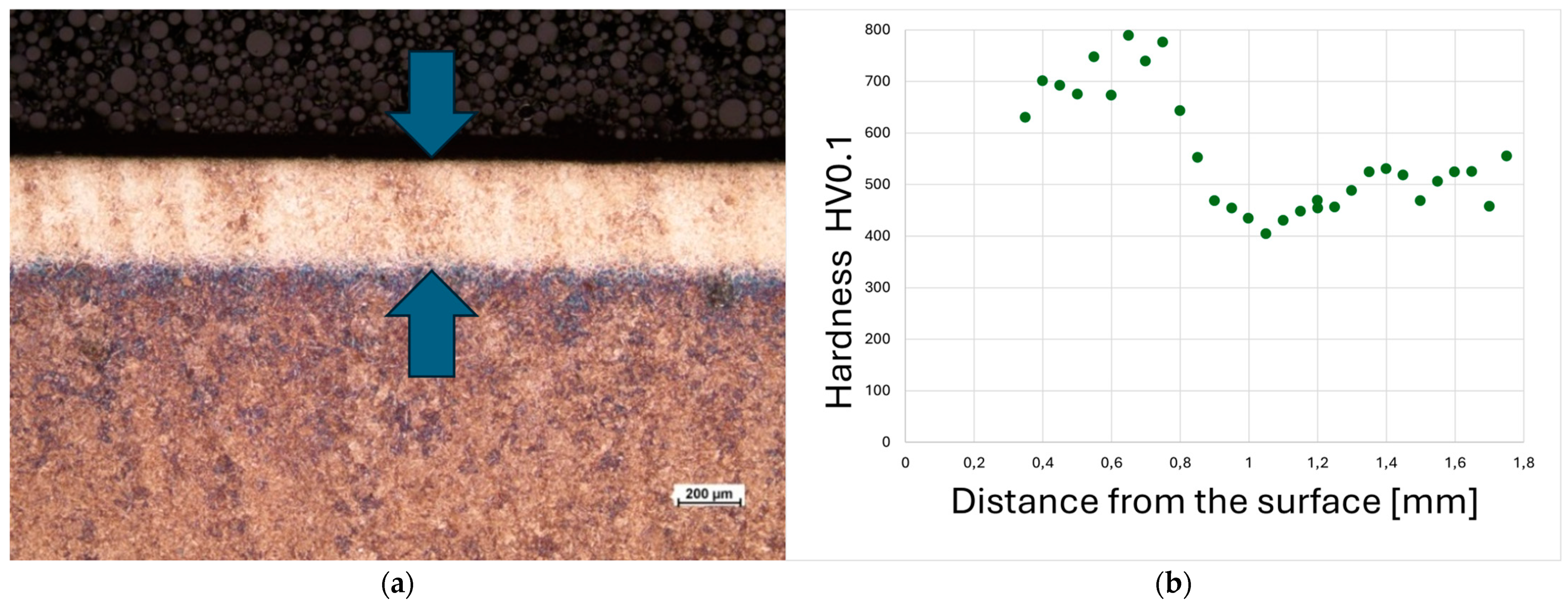
A cross-sectional view of the laser-hardened layer formed on 30HGSNA steel, along with its microhardness profile, is presented in
Figure 1. The applied treatment resulted in the formation of a hardened layer with a thickness ranging from 0.5 to 0.8 mm along the entire length of the processed zone.
Microhardness measurements confirmed the estimated depth of the hardened layer and showed that the surface hardness ranged from 700 to 800 HV. Beyond a depth of approximately 0.5 mm from the surface, the hardness gradually decreased and stabilized around 500 HV, which corresponds to the hardness of the bainitic substrate in its unquenched state (
Figure 1). Based on the uniformity of the hardness profile, the formation of a martensitic hardened layer of consistent thickness was confirmed. Following surface polishing, carbon coatings were deposited onto the samples via RFCVD at temperatures below 100 °C for 30 min. Treatments conducted under these conditions do not cause adverse changes in the microstructure of ultra-fine bainitic steels, as demonstrated in previous research [
53].
3.2. Nanohardness
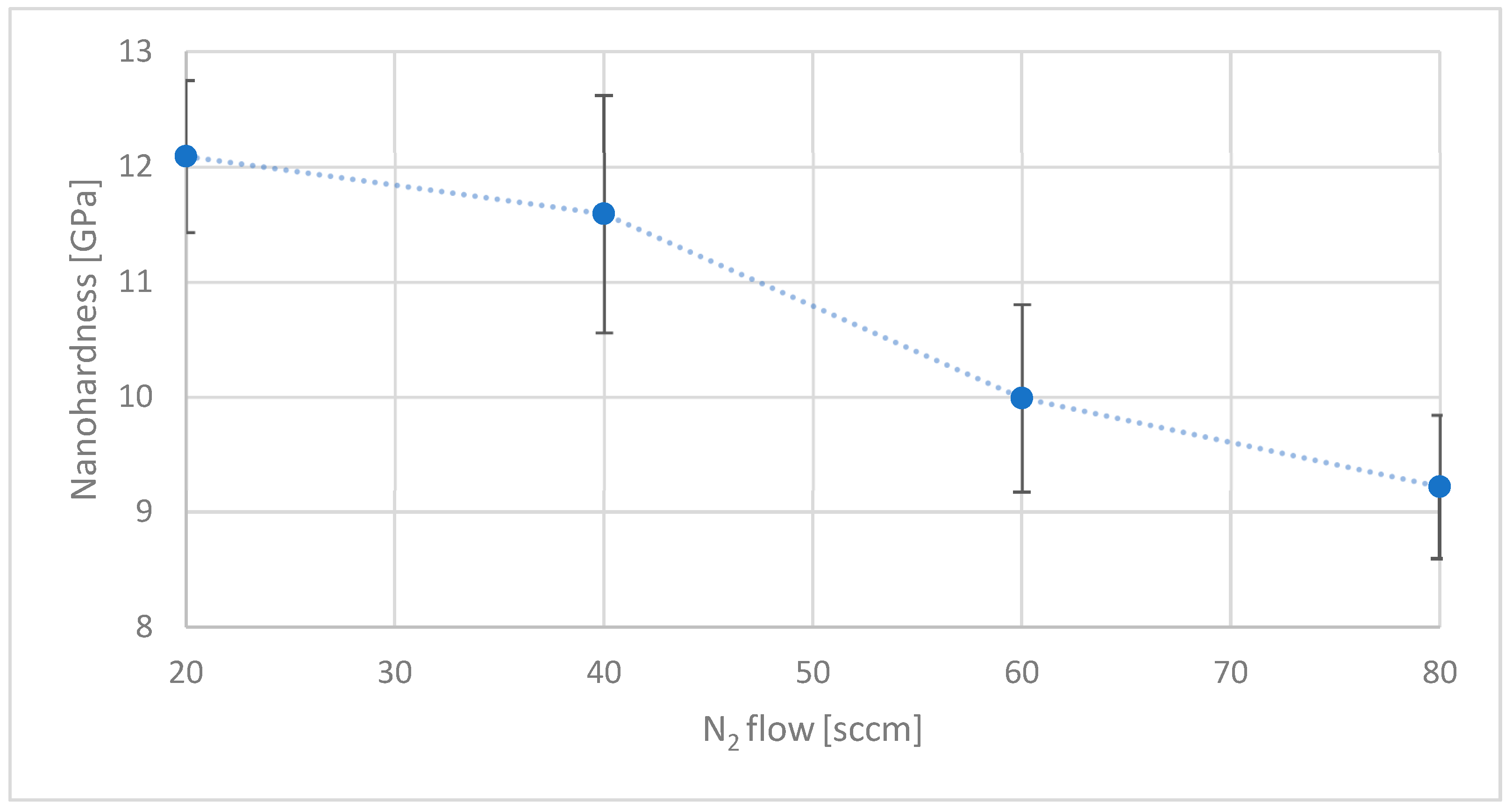
Nanohardness testing revealed that increasing the hydrogen and nitrogen content in the reactive gas atmosphere resulted in a reduction in coating hardness. The coating deposited without additional H
2 exhibited significant heterogeneity, as indicated by the large standard deviation observed during measurements. For all other samples, the variation in hardness was considerably lower, with standard deviations of approximately 2 GPa (
Figure 2). The highest nanohardness was recorded for the coating obtained in an atmosphere without added H
2. The introduction of hydrogen into the reactive atmosphere caused a decrease in hardness to approximately 12 GPa. Further increases in hydrogen concentration did not result in a comparable drop in hardness.
In the nitrogen series, it was not possible to produce a stable coating on the investigated substrate in the absence of nitrogen in the reactive mixture. Coatings deposited without nitrogen delaminated spontaneously immediately after opening the CVD chamber. Assuming that internal stresses in carbon coatings scale with hardness, it is reasonable to infer that the coatings exceeded a critical stress threshold, leading to failure. Starting from a nitrogen flow rate of 20 sccm, a further increase in nitrogen content led to a gradual reduction in coating hardness from approximately 12 GPa to 9 GPa (a value similar to surface hardness of the substrate) (
Figure 3)—a trend consistent with observations reported in the literature [
45,
46].
3.3. Scratch Test
Scratch tests conducted on carbon coatings deposited under increasing nitrogen concentrations demonstrated that the rise in nitrogen content systematically improved coating adhesion. The coating produced without nitrogen exhibited immediate delamination upon exposure to atmospheric conditions after the CVD process, which was recorded as zero adhesion (0 N) on the test graph (
Figure 4).
Similarly, attempts to produce nitrogen-doped coatings in the absence of H
2 gas in the reaction atmosphere led to spontaneous delamination or failure upon the first contact of the indenter with the surface. Consequently, all coatings for further evaluation were deposited under a constant hydrogen flow of 20 sccm. The observed correlation between improved adhesion (
Figure 4) and reduced nanohardness (
Figure 3) with increasing nitrogen flow was consistent with expectations based on prior studies performed on steel substrates [
45,
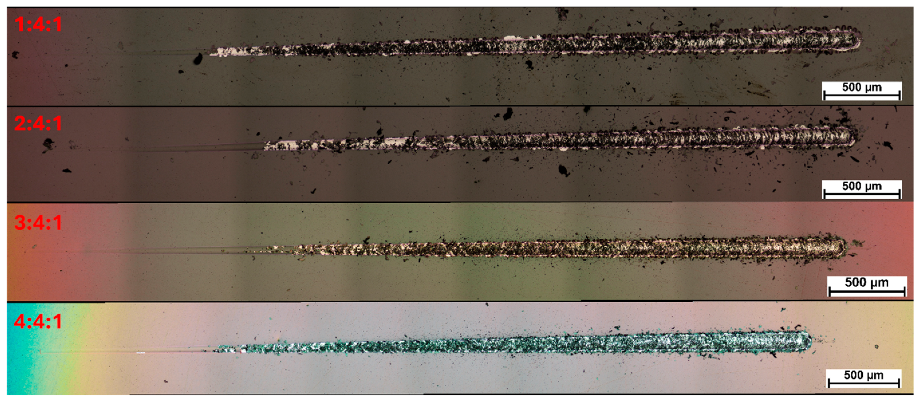
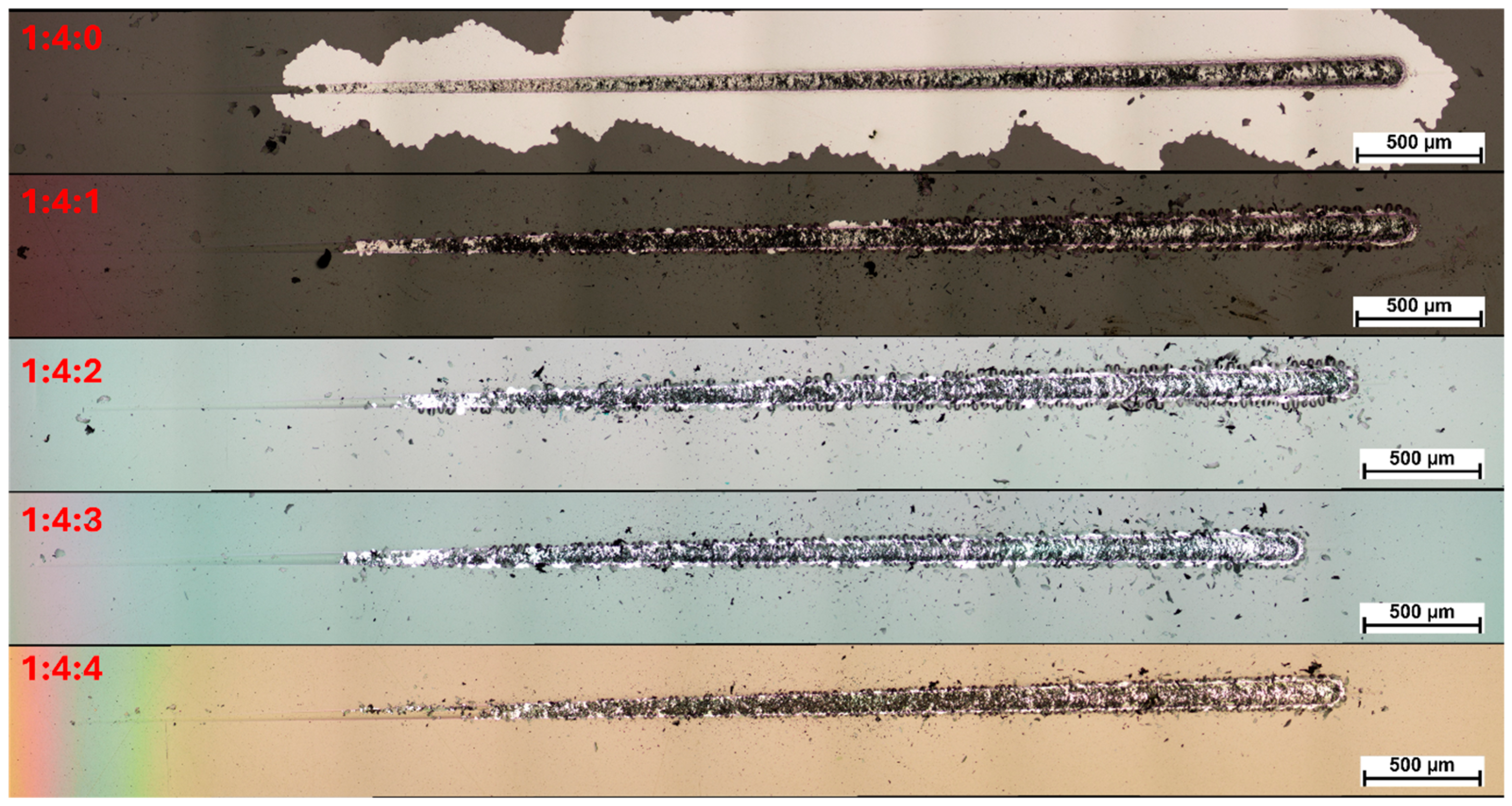
46]. Moreover, it was noted that as the nitrogen content increased, the nature of the coating failure changed. At lower nitrogen concentrations, the loss of cohesion was immediately accompanied by adhesive failure. At higher nitrogen flows (60 and 80 sccm), the coatings retained adhesion to the substrate even after transverse cracking, progressively degrading through subsequent mechanical damage (
Figure 5). At elevated nitrogen contents, significantly fewer fragments and chipping were observed along the edges of the scratch path, which is likely associated with the lower hardness of the coatings and the resulting increase in their plasticity.
Since even surface-hardened steel exhibits significantly lower hardness compared to diamond-like carbon (DLC) coatings, the reduction in coating hardness diminished the property mismatch at the interface, which contributed to mitigating the disadvantageous cracking behavior. At the same time, as the nitrogen content in the reactive atmosphere increased, a progressively more pronounced edge effect was observed, spreading from the sample edges further into its surface — as clearly documented in the microscopic images (
Figure 5 and
Figure 6). At a nitrogen flow rate of 80 sccm, this effect extended into the scratch test measurement area, which may have contributed to the observed reduction in coating adhesion.
Furthermore, in samples treated under the highest nitrogen concentration, no carbon coating was detected using a metallographic microscope at the very edge of the specimen (as seen at the bottom of
Figure 6). This phenomenon is most likely attributed to the intensification of the cathodic sputtering effect at the sample edges in a nitrogen-rich atmosphere. When a certain nitrogen concentration threshold is exceeded during the RFCVD process, in addition to nitrogen incorporation into the coating structure, the bombardment effect also leads to the ejection of carbon atoms—the fundamental building blocks of the coating—from the substrate surface. As a result, the nitrogen-to-methane ratio of 3:4, corresponding to a nitrogen flow of 60 sccm, was identified as the most favorable composition.
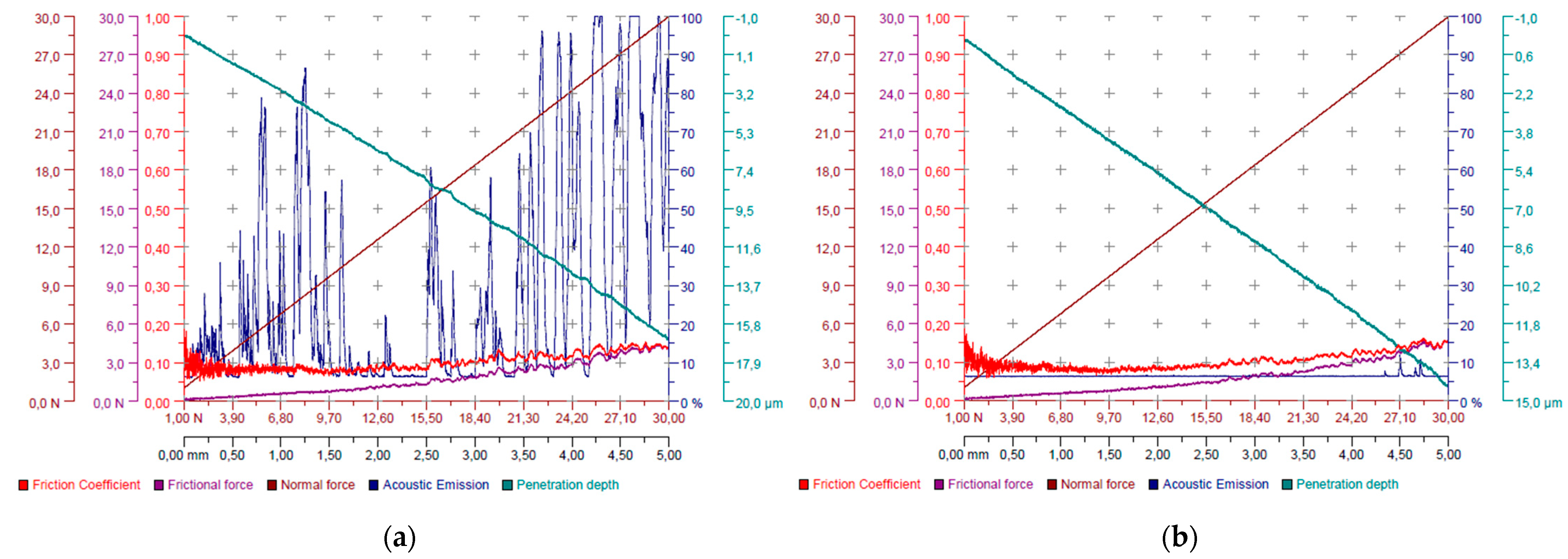
During the scratch test, it was observed that an increase in nitrogen content led to a substantial reduction in measured acoustic emission (
Figure 7). This may be attributed to the previously noted decrease in hardness and internal stresses, as the coating releases less energy upon cracking and exhibits greater elasticity under load. It is worth noting that, in the case of the 4:4:1 sample, the acoustic emission did not correlate with the visible damage sustained by the coating. Therefore, the points of initial damage and complete delamination were determined based on visual inspection.
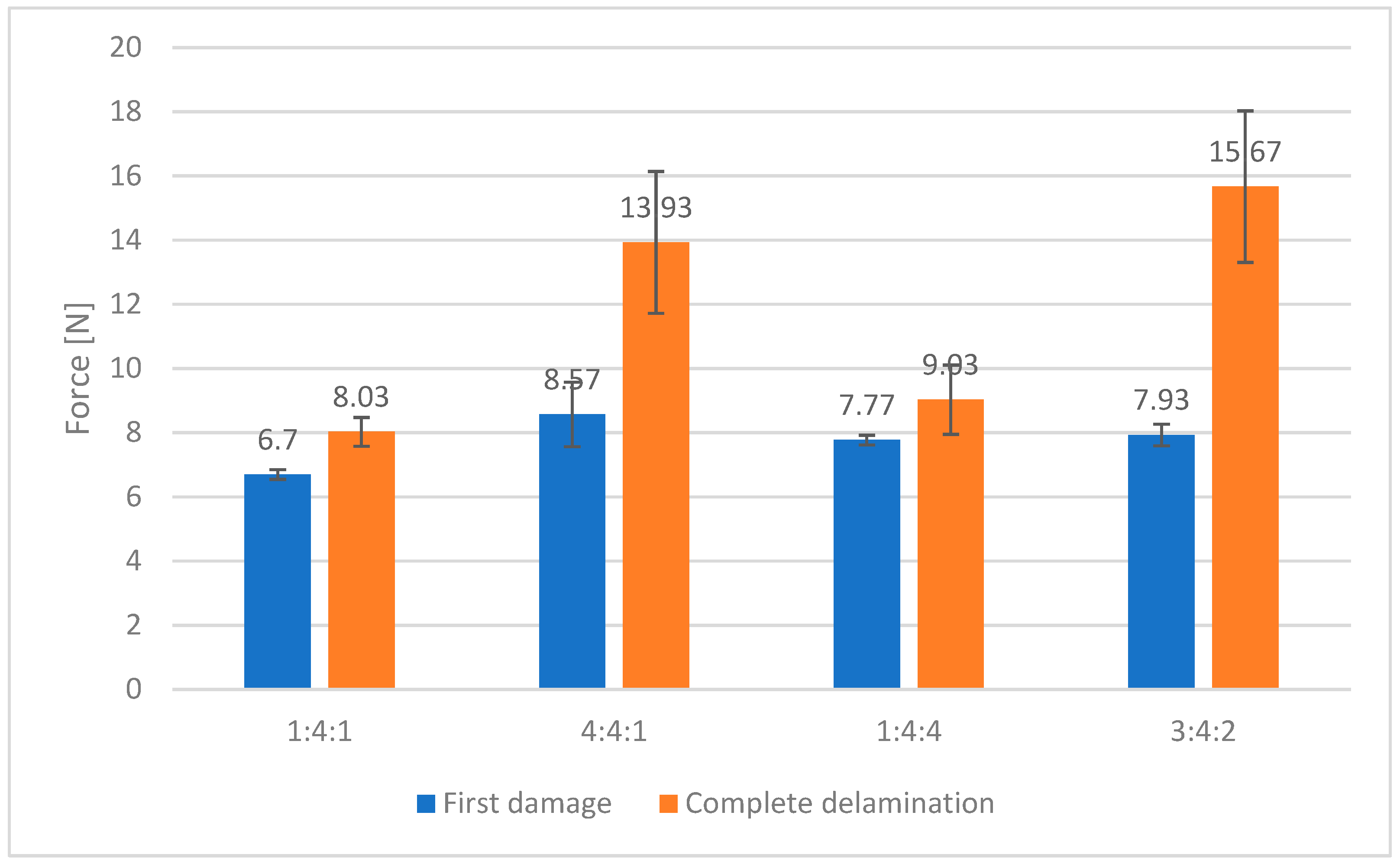
In the course of assessing the effect of hydrogen concentration in the reactive gas mixture on coating adhesion, it was found that the presence of nitrogen at a minimum flow rate of 20 sccm was necessary to produce a coating that did not undergo spontaneous delamination upon opening the CVD chamber. All coatings included in this study were therefore synthesized at this nitrogen flow rate. No clear or statistically significant trend was observed in the adhesion values with increasing hydrogen content—both initial failure points and complete delamination were recorded at indenter loads ranging between 7 and 9 N (
Figure 8).
Nevertheless, a distinct difference in the failure mechanism was observed between the coatings produced without additional H
2 and those doped with even minimal amounts of hydrogen. Hydrogen-modified coatings exhibited localized failure confined to the immediate vicinity of the indenter contact point, whereas coatings produced without additional H
2 in the RFCVD process displayed progressive chipping, propagating from the site of initial cohesive failure. In the case of coatings synthesized without additional hydrogen, loss of cohesion immediately resulted in adhesive failure, causing the coating to delaminate from the substrate. In this scenario, the coating’s adhesion was clearly insufficient to compensate for its internal stresses, which ultimately led to complete disintegration. In fact, within a short period following the scratch test, the entire coating spontaneously delaminated, preventing further repetitions and statistical evaluation (
Figure 8 and
Figure 9).
As the hydrogen content increased, the loss of cohesion no longer implied simultaneous adhesive failure. This change was reflected by the growing distance between the points of initial damage and total delamination in the scratch test results. Similarly to the nitrogen series, the presence of hydrogen also promoted the formation of an edge effect, although the intensity of this phenomenon was noticeably lower. This is likely due to the lower molecular mass of hydrogen, which results in a reduced cathodic sputtering efficiency. Based on these observations, the optimal hydrogen-to-methane ratio was determined to be 2:4, which corresponds to a hydrogen flow of 40 sccm.
The same tendency as in the case of nitrogen-doped coatings appeared, as hydrogen content increased, acoustic emission decreased.
Based on the findings presented above, a carbon coating was also synthesized using a mixed gas composition with a nitrogen-to-methane-to-hydrogen ratio of 3:4:2, and its adhesion performance was subsequently evaluated (
Figure 10). In this case, the first signs of coating damage were observed at an indenter load of approximately 8 N, while complete delamination did not occur until the load reached 15.7 N. These values were compiled and presented alongside data from coatings produced under boundary gas compositions, for comparison.
The coating produced under the mixed gas atmosphere (3:4:2) demonstrated the highest load-bearing capacity before total failure. However, the loads corresponding to the onset of damage were comparable for the samples produced at gas ratios of 4:4:1, 1:4:4, and 3:4:2, all falling within the margin of experimental error. Further investigations were focused exclusively on samples representing the boundary gas compositions, to highlight the specific influence of each gas component, and on the 3:4:2 sample, which had shown the most promising performance for practical tribological applications (
Figure 11).
3.4. Raman Spectroscopy
Figure 12 shows Raman spectra of the hydrogenated DLC coatings produced in different reactive atmospheres with calculated sp
3 content from Equation (1). The measured spectra were fit with five elementary components. The parameters of elementary components are shown in
Table 4. A single crystal graphite shows a Raman active band E
2g, labeled as G (Graphite), at ~1580 cm
−1. G peak is a representation of the stretching modes of sp
2 sites. With the amorphization, an A
1g mode appears at ~1350 cm
−1, known as the D peak (Disorder) [
3,
57]. D mode is assigned to breathing modes of sp
2 sites in graphite rings. In the measured spectra, we identified additional modes related to the active presence of hydrogen in the coating material. They are recognized in the literature as characteristic of transpolyacetylene (Trans-PA):
chain stretching vibrations ~1150 cm
−1 of Trans-PA [
55,
58] and
“wagging” vibrations ~1450 cm
−1 of Trans-PA [
55]. The “dumbbell” interstitial defects appearing ~1700 cm
−1 have also been identified [
55,
59,
60].
Calculated sp
3 contents from Equation (1) were presented in
Figure 12. At first glance, the spectra are similar, and as a result, it can be concluded that their phase composition in the form of amorphous carbon with a certain amount of sp
3 bonds is similar. This is evidenced, for example, by the
ratio of ~85%. Calculated from Equation (1), the sp
3 content is about 20%. It is worth noting that the calculated sp
3 content from Equation (1) shifts slightly with the
ratios of the samples, with a trend in the Ferrari diagram of three-stage carbon amorphization [
61]. The results of the characterization of hydrogenated amorphous carbon coatings by Raman spectroscopy correspond well with XPS results.
3.5. XPS
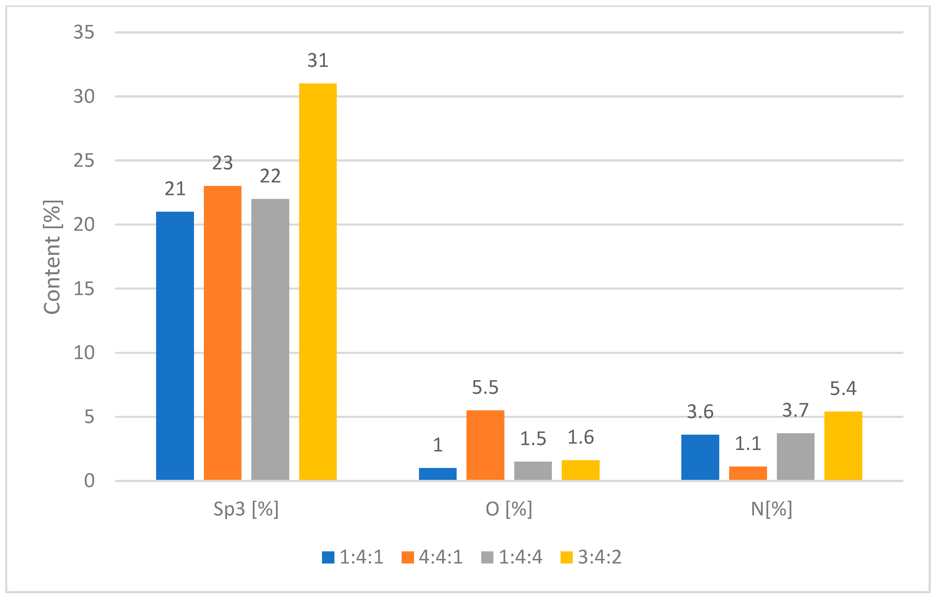
To find out the chemical composition of the carbon coatings formed during the RFCVD process, the XPS measurements were performed. All tested surfaces consist mostly of carbon (95.3–92.9 at.%), low amounts of nitrogen (5.4–1.1 at.%) resulting from the reaction atmosphere, and oxygen (5.5–1.0 at.%) (
Figure 13). The presence of oxygen could be the consequence of impurities introduced into the coatings during the deposition or annealing process.
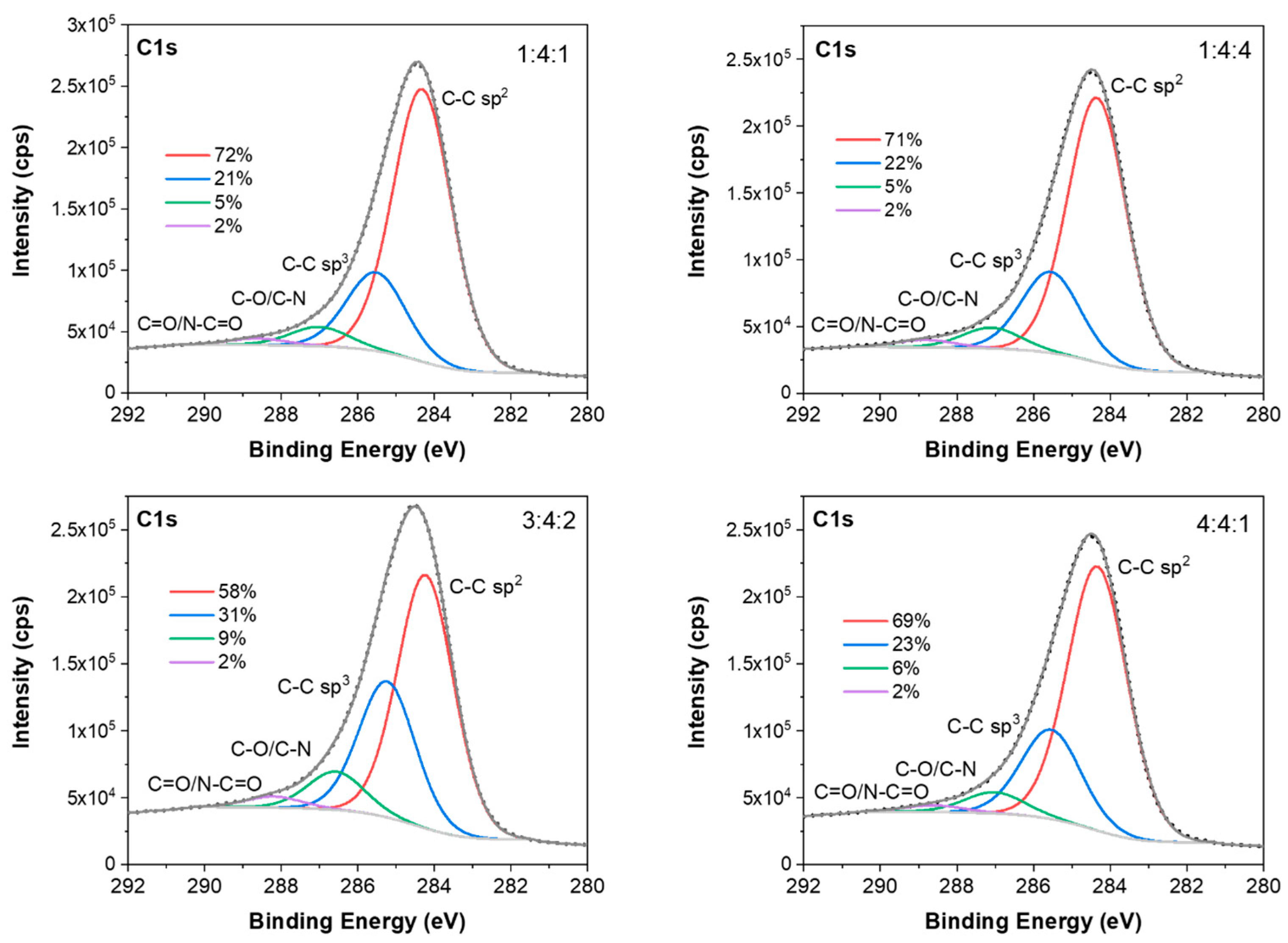
In
Figure 14, the fittings of C 1s spectra for the investigated coatings are shown. The fitted C1s spectra consist of two major peaks at about 284.3 and 285.5 eV originating from C-C sp
2 and C-C sp
3 bonding in carbon coatings [
48]. The other two minor peaks present in these spectra at higher binding energies (about 287.0 and 288.5 eV) are related to oxygen and nitrogen functional groups (C-O/C-N and C=O/N-C=O, respectively) [
62].
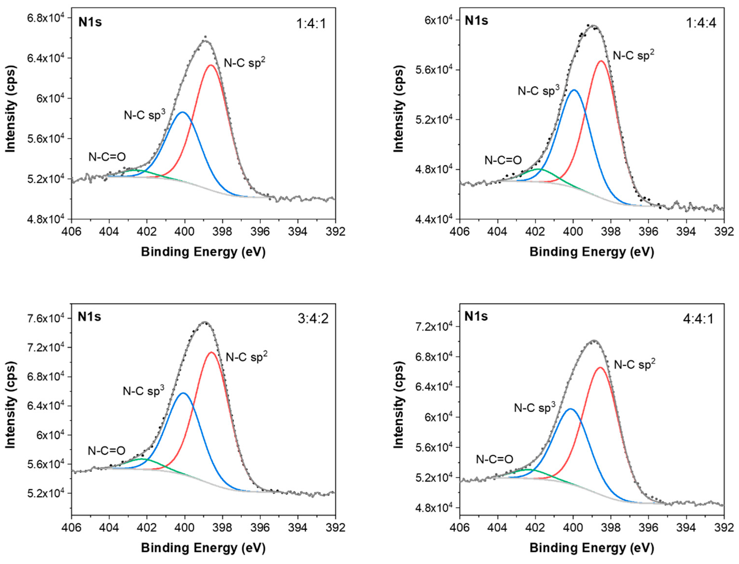
The N1s spectra of carbon coatings were fitted into three peaks, as shown in
Figure 15. The peaks located at about 398.5 eV and 400.0 eV correspond to N atoms bonded to sp
3-coordinated C atoms (N-C sp
3) and N atoms bonded to sp
2-coordinated C atoms (N-C sp
2), respectively [
62]. The peak at about 402.3 eV was assigned to the N-C=O bond [
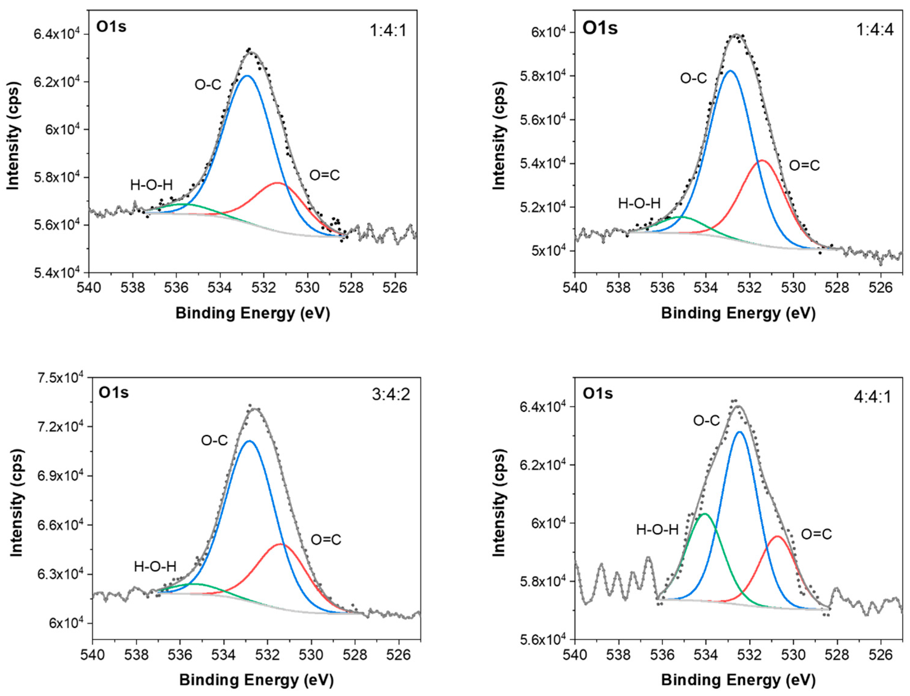
62]. The fitted O1s spectra (
Figure 16) consist of three peaks at about 531.2, 532.4, and 534.5 eV that correspond to C=O, O-C-O, and H-O-H bonds, respectively.
With the help of that method, the share of sp3 bond was determined by a suitable fitting of the XPS C 1s energy peaks. The noticeably higher share of C-C sp3 bond was revealed for 3:4:2 carbon coating (31%) than for the other coatings under investigation (21%–23%). For this sample, the content of nitrogen also reached the highest value of 5.4 at.%.
It should be noted, however, that the XPS measurements allow one to study only the first 10 nm of the surface layer. In accordance with the results obtained in this study, the thickness of the investigated carbon coatings is a few hundred nanometers.
3.6. SEM
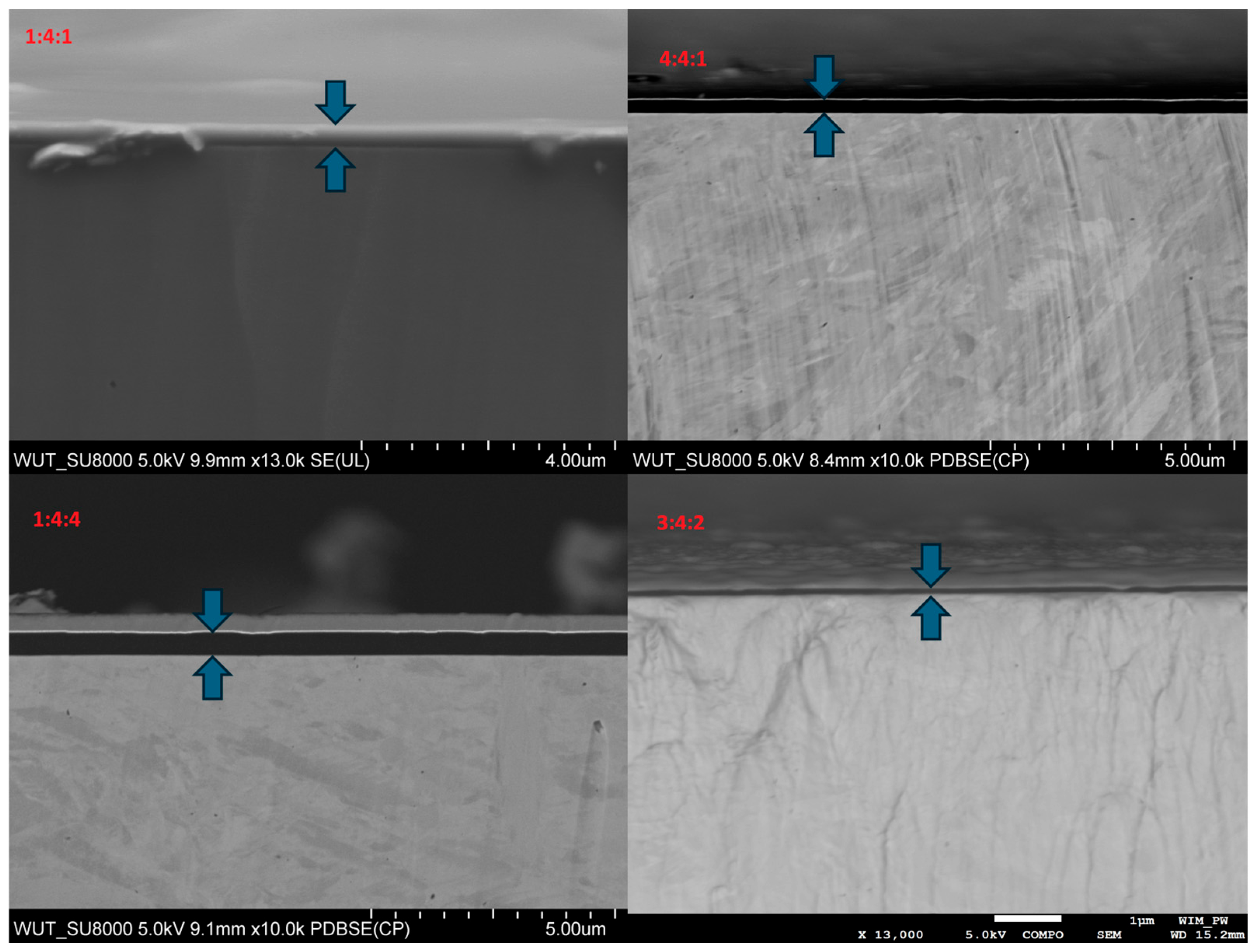
All carbon coatings observed in cross-sections exhibited a continuous, amorphous structure, and their thickness ranged from 90 to 500 nm. The substrate beneath the coating showed a martensitic microstructure. The streaks visible on the surface of the metallic substrate were formed during ion cutting of the analyzed sample area and indicate the significantly higher hardness of the coating compared to the substrate (
Figure 17).
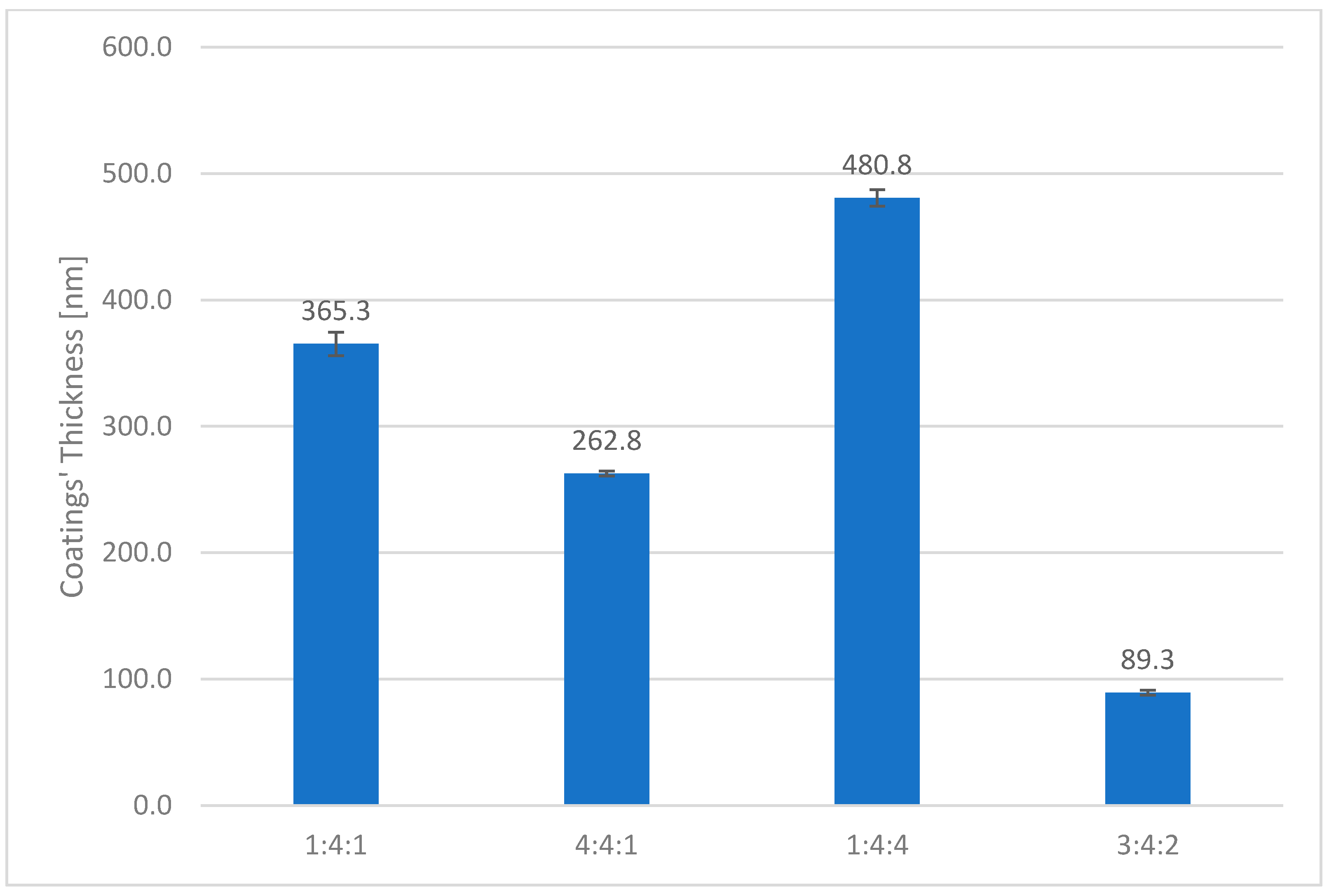
It was also observed that the thickness of the carbon coating decreased as the nitrogen content in the reactive atmosphere increased (
Figure 18). This can be attributed both to the lower concentration of methane, the primary carbon source, and to the intensified cathodic sputtering occurring in nitrogen-rich environments. This effect was also clearly visible in the surface micrographs (
Figure 17). In addition, the thickness of the carbon coating was found to decline as the proportion of non-carbon-carrying gases in the atmosphere increased, as evidenced by the fact that the thinnest coating was produced under the 3:4:2 gas composition. Conversely, the sample fabricated under the lowest nitrogen content (1:4:4) exhibited the greatest coating thickness (
Figure 18).
3.7. Ball-on-Disc Tests
In the ball-on-disc wear resistance tests, measurements of the friction coefficient were performed to analyze the behavior of the carbon coatings. The tests were conducted under conditions that allowed the progressive degradation of the coatings to be observed. The behavior of the coating after its structural continuity is compromised can significantly influence the wear rate of the substrate—the hardness of the coating, along with the geometry of the resulting fragments, may accelerate substrate wear by acting as an abrasive medium. Such a scenario is undesirable for coatings intended for technical applications and should be avoided.
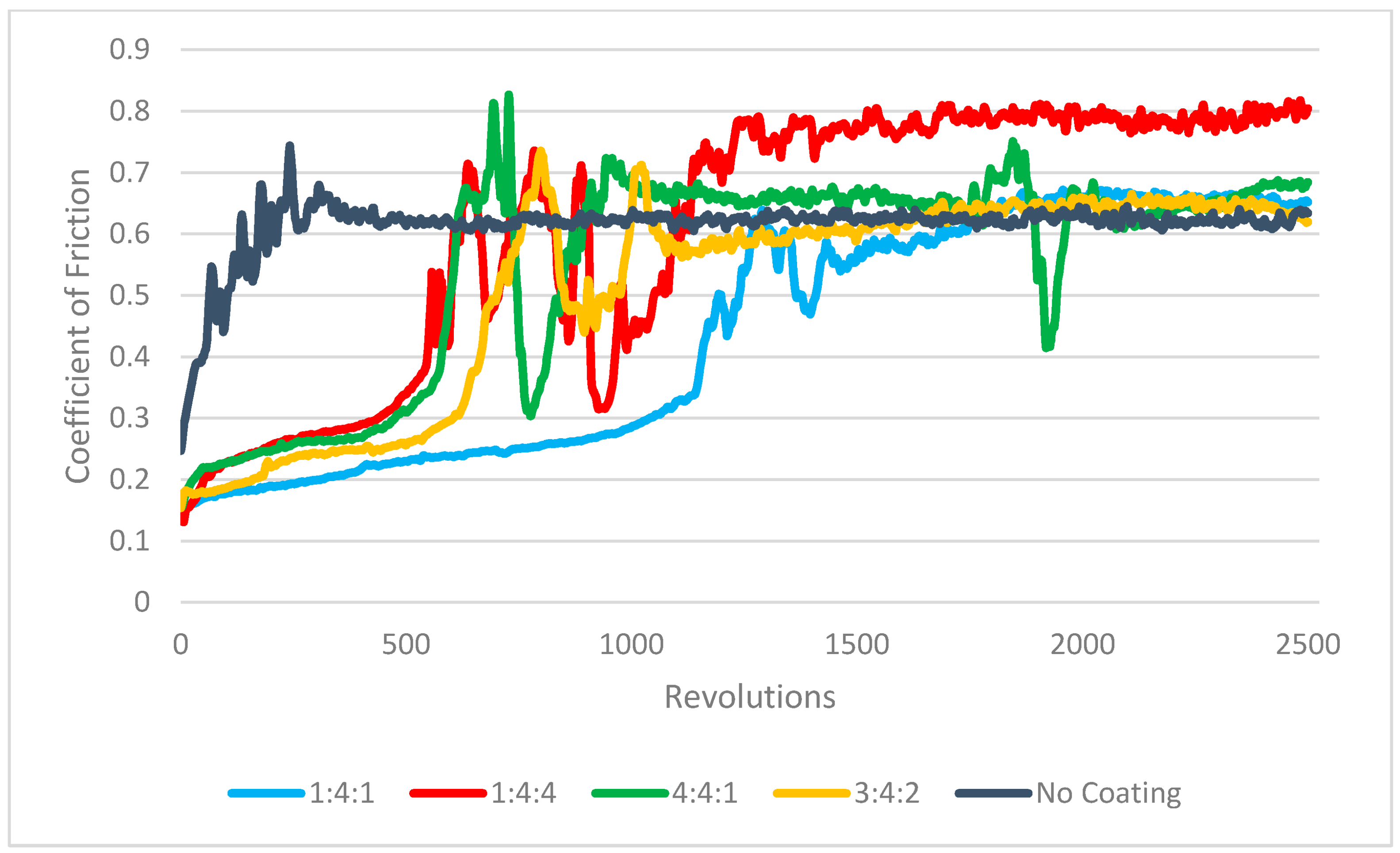
The friction curves obtained for each sample clearly exhibited three characteristic stages of tribological contact. In the initial phase, surface adaptation and gradual wear of the carbon coating occurred. During this stage, the friction coefficient was considerably lower than the value observed for steel–alumina contact and steadily increased as the contact area between the alumina counter-sample and the coating grew, which in turn increased the friction force. For all tested samples, the coefficient stabilized within the range of 0.2–0.3. In most cases, this initial phase lasted for approximately 600 cycles, whereas for the coating produced in the 1:4:1 gas mixture, the duration was roughly twice as long (
Figure 19). In the second stage, the coating experienced fracture and gradual disintegration. During this phase, the friction coefficient exhibited significant fluctuations, which were attributed to the fragmentation of the carbon coating, the accumulation of its debris on the counter-sample surface, the agglomeration of these particles, and their subsequent detachment. In the final stage, the friction coefficient stabilized at a level characteristic of direct contact between the ceramic ball and the metallic substrate, falling within the range of 0.6–0.7. A slightly higher friction coefficient was recorded for the sample with a 1:4:4 gas composition, which may be associated with an increased surface roughness of the substrate following coating failure (
Figure 19).
Microscopic examination of the wear tracks revealed the formation of deep grooves along the sliding path of the counter-sample on all surfaces (
Figure 20). Although this feature was present in all cases, it was particularly pronounced on the reference sample and the 4:4:1 sample, which is likely related to the inherent properties of the substrate.
The coating on the 4:4:1 sample exhibited the fastest failure, as indicated by the early stabilization of the friction coefficient at approximately 0.65—a value typical for steel–alumina contact after coating loss. Consequently, the deepest wear tracks were observed on uncoated samples or on those where the coating had failed prematurely.
After the tests, a blackish-brown powder was found on the surface of all samples and the counter-sample. This debris consisted of remnants of both the carbon coating and the martensitic substrate. Once detached due to abrasive wear, these particles were transferred onto the counter-sample, where they acted as an additional abrasive during subsequent sliding cycles. Due to the high hardness of the substrate, the wear mechanism was dominated by cracking and fragmentation rather than plastic deformation.
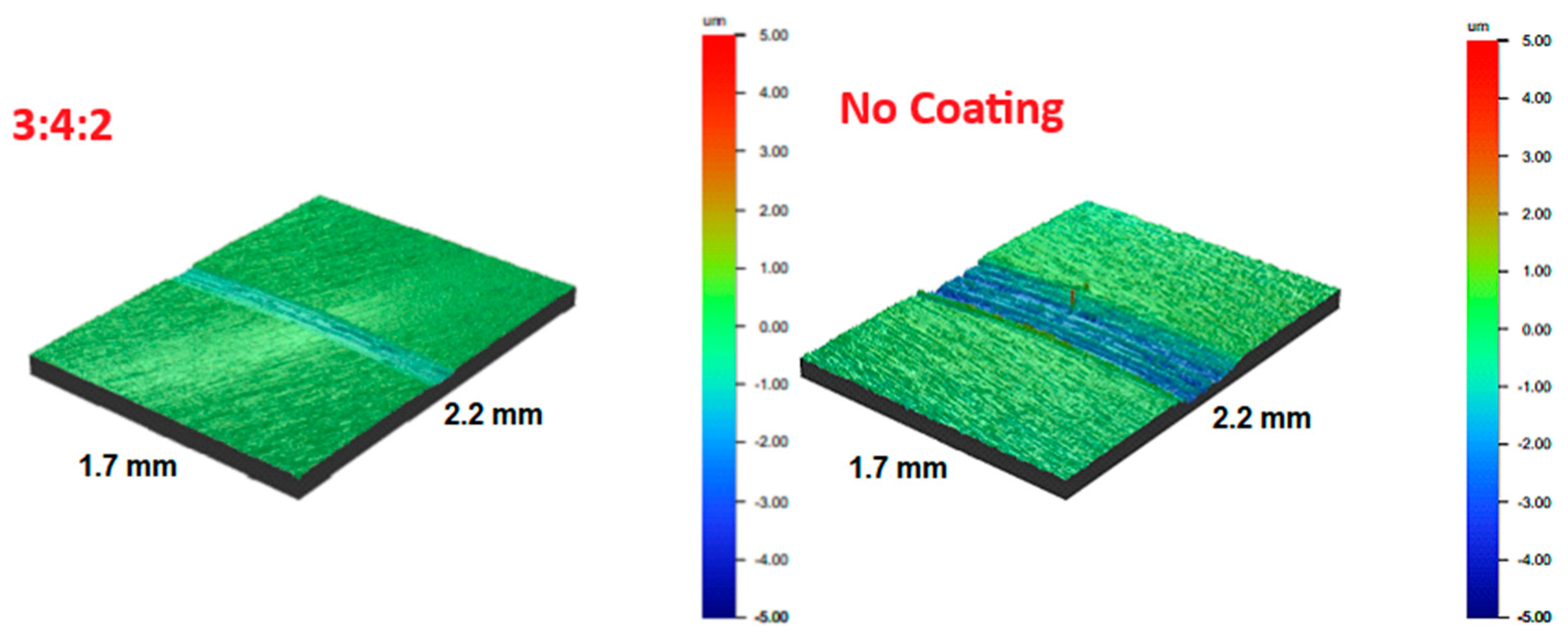
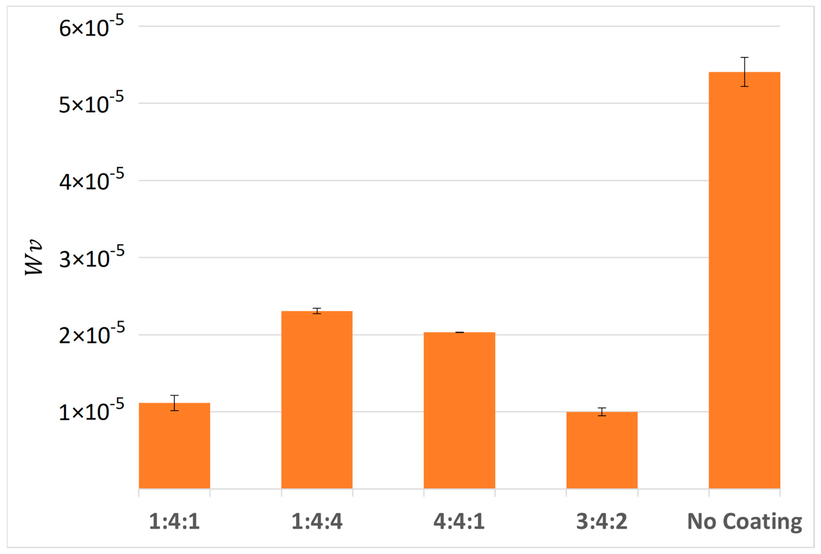
Measurements performed using an optical profilometer, combined with calculated specific wear rates, confirmed that the lowest wear was recorded for the 1:4:1 and 3:4:2 samples. Once again, the deepest grooves were observed on the reference sample (
Figure 21), the 4:4:1, and the 1:4:4 sample, which had failed the fastest. The difference in specific wear rate, calculated using Equation (2), between the 4:4:1 and 1:4:4 samples, and the best-performing 3:4:2 sample, was more than twofold. All coated samples exhibited significantly higher wear resistance compared to the uncoated reference sample, whose wear rate was over five times greater than that of the best-performing coating (3:4:2) (
Figure 21).
It is worth noting that no clear correlation was observed between the coating thickness and its wear resistance (
Figure 18,
Figure 22).
4. Discussion
The amorphous carbon coatings doped with hydrogen and nitrogen, produced under various reactive atmosphere compositions, exhibited a progressive decrease in hardness as the hydrogen and nitrogen content in the RFCVD atmosphere increased. The obtained results are consistent with previous literature reports describing the effect of nitrogen on the properties of carbon-based coatings. Typically, increasing the nitrogen content leads to a simultaneous reduction in hardness [
15], internal stress [
44], and the proportion of sp
3 bonds [
42,
43].
While the first two relationships were clearly observed, the sp
3 bond fraction was not the lowest for the sample produced at the highest nitrogen flow rate. This anomaly is most likely attributed to the simultaneous decrease in hydrogen content in the reactive gas mixture, which promoted the incorporation of oxygen—present as an impurity—into the coating structure. The presence of oxygen may have hindered nitrogen bonding, paradoxically resulting in the lowest nitrogen content in the coating synthesized under the nitrogen-richest atmosphere. Similarly, the 3:4:2 sample exhibited the highest sp
3 bond fraction despite its high nitrogen content, which is somewhat unexpected in light of the reported literature data on the behavior of nitrogen [
43].
In the case of hydrogen, increasing its concentration also led to a slight reduction in coating hardness, which is consistent with the trends reported for hydrogen-rich reactive atmospheres [
39,
41] and corresponds well to the hydrogen-to-carbon ratios employed in this study. Interestingly, no significant increase in sp
3 bond content was observed when using atmospheres containing a single dopant gas. For both nitrogen- and hydrogen-rich coatings, the sp
3 bond proportion remained within the range of approximately 21%–31%, as confirmed by both Raman spectroscopy and XPS analysis. The expected decrease in the sp
3/sp
2 ratio for the nitrogen-rich coating [
42] did not occur, most likely due to the competing effect of oxygen incorporation, which is known to promote sp
3 bond formation and thus slightly increase the sp
3/sp
2 ratio despite the high nitrogen content.
Notably, when both dopants (hydrogen and nitrogen) were introduced simultaneously, the sp
3 bond fraction increased significantly. Despite this, the coating hardness was reduced—most likely due to a stronger substrate effect on the measurements, since the coating deposited under this atmosphere exhibited the lowest thickness. As expected, the reduced hardness of the carbon coatings translated into improved adhesion to the metallic substrate, which is a well-established trend in the literature [
14,
47]. Beyond the absolute values of critical loads for coating failure, the post-failure behavior of the coatings is of equal importance for practical applications. The progressive delamination observed in hydrogen-free coatings would be unacceptable in real-world tribological conditions. Additionally, increasing the concentration of non-carbon-carrying gases in the reactive atmosphere led to a reduction in coating thickness. At a constant process time, this reflects a lower growth rate, which is an anticipated effect [
38,
40]. It is worth noting that the produced coatings reached thicknesses that, even in the case of undoped carbon coatings deposited on silicon substrates, often exceed the critical stress threshold for spontaneous delamination [
63]. This phenomenon was indeed observed for coatings synthesized without hydrogen or nitrogen in the gas mixture.
Tribological tests confirmed that the applied carbon coatings—regardless of the gas composition—significantly reduced the wear coefficient compared to the uncoated steel substrate. Analysis of the friction coefficient curves showed that, as long as the coating remained structurally intact, it effectively reduced friction in comparison to the bare substrate. The most favorable performance in terms of wear resistance was observed for the coating produced under the 3:4:2 gas mixture, followed closely by the 1:4:1 coating. The highest enhancement in wear resistance was therefore recorded for the coating with the highest measured hardness (1:4:1) and for the coating exhibiting the highest sp
3 bond fraction but lower hardness and thickness (3:4:2), likely due to a higher content of non-carbon–carbon bonds in the structure. An increase in wear resistance with coating hardness is well documented in the literature, although this relationship has mostly been observed for carbon coatings deposited on silicon substrates, where the hardness mismatch between the coating and the substrate is significantly smaller [
12]. In the case of steel substrates, the tribological performance of carbon coatings is typically limited more by their adhesion than by their hardness, particularly in the absence of an interlayer. It is also reported that nitrogen-doped carbon coatings, while softer, exhibit superior adhesion to soft substrates, which can result in longer service life in practical applications [
15,
16,
46]. Despite differences in deposition technique, a similar trend was reported by Kao et al. [
15], confirming the consistency of the observed behavior.
Interestingly, no correlation was found between the coating thickness and its wear resistance under the tested conditions. As demonstrated in this study, for very hard coatings, the loss of cohesion can trigger progressive adhesive failure, exposing the underlying substrate and eliminating the protective effect of the carbon layer. Therefore, the improved adhesion of the 3:4:2 coating is the most plausible explanation for its lowest recorded wear rate.
The oxygen content in the coatings ranged between 1% and 2%, except for the sample produced under the 4:4:1 gas mixture. In this case, the sp
3 bond fraction was among the highest observed (second only to the 3:4:2 coating), although this did not translate into superior wear resistance. This is most likely due to the simultaneously reduced coating thickness. According to the literature, oxygen incorporation can promote an increase in sp
3 bond content, which enhances both hardness and wear resistance as well as adhesion [
49]. However, these studies were conducted on silicon substrates, where the property mismatch between coating and substrate is much smaller, and therefore less limiting for adhesion compared to the steel–DLC system. A similar increase in sp
3 bond content was observed here, but it did not lead to improved hardness, likely due to differences in deposition technique. The present results do not allow for a clear determination of the relationship between oxygen content and tribological performance, and the influence of other elemental components appears to be more significant.
In conclusion, under the assumption of a fixed deposition time, the most effective coatings for improving the wear resistance of steel substrates were those deposited in the 1:4:1 atmosphere—characterized by the highest methane content and hardness—and in the 3:4:2 atmosphere, which exhibited the highest nitrogen content, sp3 bond fraction, and adhesion, albeit lower hardness and thickness. Both trends are consistent with the data reported in the cited literature.
Enhancing adhesion through laser hardening and simultaneous nitrogen and hydrogen doping while manufacturing the DLC coating proved to be an effective strategy, resulting in a notable improvement in the functional properties of the coatings. Such an approach allows for coating temperature-sensitive materials such as UFGB steels and can be applied to other types of structures with limited thermal stability. Further optimization of the parameters of the RFCVD process (such as polarization potential, process pressure, or surface roughness) for coatings deposited in nitrogen-rich and hydrogen-rich atmospheres could improve the coating thickness and consequently its durability.
