Abstract
When processing widely used materials in welded structures such as steels, a surface operation such as plasma cutting applied in the automated Computer Numerical Control (CNC) version can provide technical and economic benefits to the cut components, but the impact on health and environment must be addressed accordingly. In this paper, a plate with a base material made of S355J2 + AR structural steel is cut in 10 pieces with plasma in a water-bed designed and manufactured by the authors in order to mitigate such risks. The surfaces cut in the water-bed are compared to surfaces cut in open air by macroscopic analyses of the edge cut, by microscopic analyses of the cut parts—base material, heat-affected zone, and cut area—and by hardness determinations. The results reveal improvements as a result of plasma cutting in the water-bed: slag reduction, preservation of granulation, transformations in the austenitic temperature zone, and hardness in the heat-affected zone. Compared to a classical cutting procedure such as oxygen flame cutting, the proposed procedure offers a clean alternative and also requires low maintenance.
1. Introduction
One of the major challenges of structural applications is to develop modern steels that can withstand a fluctuating stress environment and ultra-low cycle fatigue, as presented in [1,2]. One study [3] has provided a prediction on the long-term strain ageing effects on the stress–strain behavior of low-carbon structural steels with nominal yield strengths ranging from 235 MPa to 355 MPa. Due to its high strength, S355 steel is frequently used in civil engineering to design bridges and simple engineering parts [4,5], being able to meet strict construction requirements with relevant savings in materials. According to [6], S355J2 steel is a non-alloyed structural steel with a minimum yield strength of 355 MPa and a typical tensile strength between 470 and 630 MPa. The mechanical response and microstructure of steel coatings deposited by applying two spraying techniques onto this steel were determined in [7]. By microstructural analysis, tensile testing, hardness testing, and fracture toughness testing using specimens derived from various zones of the weld joints by using the Rotary Friction Welding (RFW) technique, significant microstructural differences were revealed across the weld joints tested in [8], obtaining a stable hardness with a maximum of 208 HV1 in the thermo-mechanically affected zone (TMAZ). Changes in microstructure are also treated in [4,9] and in hardness in [10,11]. Other relevant aspects related to S355-based applications for welded structures are also analyzed, such as: wear resistance [9,10], cracking [12], corrosion [11], fatigue behavior [5,11,13,14], X-ray inspection, and cross sections [15]. As depicted in [5,7,8,9,10,11,12,13,14], S355J2 is a low-carbon structural steel that comes in different base material variants with similar chemical composition: C = 0.015%–0.024%, Mn = 1%–1.6%, Si = 0%–0.55%, Cu = 0.04%–0.55%, P = 0.01%–0.05%, S = 0.002%–0.05%, and Fe = Balance. The base material tested herein, S355J2 + AR (as-rolled) steel, has a similar chemical composition, as presented in Table 1.

Table 1.
Chemical composition of S355J2 + AR (%) SR EN 10025/25-2004 steel, according to the analysis bulletin issued by the manufacturer.
Many types of workpiece materials used in production require more or less complicated cutting operations [16]. In terms of cutting metals, the following technologies stand out, which, depending on the source, are either thermal, such as plasma, laser, and oxygen cutting [17,18], or mechanical, such as abrasive water jet cutting [19].
The relevance of applying these cutting methods in steel processing is discussed in various studies, such as [20,21,22,23,24,25,26,27,28,29,30,31,32,33,34,35,36,37,38,39,40,41,42,43] for plasma cutting, [17,18,24,25,26,27,38,39,40,41,42,43,44,45,46] for laser cutting, [17,18,20,25,34,35,37,39,40,41,43] for oxygen/oxyfuel cutting, and [16,19,22,25,38,39,40,41,43,47,48,49] for abrasive water jet cutting.
The plasma cutting process is a modern non-conventional manufacturing process mostly used in shipbuilding and the metal processing industry. Related to its use in buildings, shipbuilding, or in any loaded structure edges, mechanical processing can only be performed by grinding and not by cutting. In this process, highly ionized gas containing a very high amount of energy is used to cut different metals such as mild steel, stainless steel, wear- and abrasion-resistant steel, aluminum, copper, etc., at various thicknesses up to 150 mm. Cut characteristics such as cut quality can be affected mostly by different process parameters that are set by a technologist or process engineer. Usually, it is the case that appropriate process parameter settings improve some quality characteristics and worsen others. Due to that, it is desirable to conduct comprehensive research in order to define optimal cutting areas where different responses related to cut characteristics simultaneously have optimal solutions. In order to accomplish that, many researchers worldwide have performed investigations in order to describe the effects of different process parameters and to define their optimal values [50].
In terms of cutting performance and quality, plasma cutting can lead to better results than oxygen flame cutting and, in some cases, to similar results as laser cutting and abrasive water cutting, especially for thick sections which are cut faster and for obtaining smooth edges. When it comes to process versatility, overall costs, maintenance, and material requirements, plasma cutting can be considered the best alternative. Only oxygen flame cutting is just as cost-effective.
Related to health safety and environmental impact, all the cutting methods mentioned previously pose specific risks. In the case of plasma cutting, the following risk assessment issues must be addressed: noise can represent an issue and underwater cutting and proper ventilation are recommended. A solution to mitigate such risks, which is rarely treated in the literature, could be the addition of a water-bed to the cutting procedure. As presented in [45], metal–ceramic elements were cut with an abrasive jet through a plasma-spraying technique in a water-bed.
In this paper, a plate with a base material made of S355J2 + AR structural steel, according to the SR EN 10025/25-2004 standard [51], having the following dimensions, a length of 900 mm, width of 700 mm, and thickness of 6 mm, is cut with plasma both in air and a water-bed by means of a CNC (numerical control cutting) machine. This paper analyzes the surface quality of the components (10 square-shaped pieces with a side of 90 mm) cut with plasma. In this regard, the following surface characteristic analyses were performed: macroscopic comparative analyses of the edge cut with plasma in a water-bed and in air, microscopic comparative analyses of the cut parts (base material, heat-affected zone, cut area), and hardness determinations.
In Section 2, the materials used and the experimental set-up for the plasma cutting operation are detailed, including the water jet and water-bed design description, the research logistics, and also the experimental procedure that is used in order to analyze the samples cut with plasma in open air, in the water-bed, and afterwards, with the oxygen flame. In Section 3, macroscopic, microscopic, and hardness analyses of the samples are provided, also including energy dispersive X-ray analysis (EDS). In Section 4, the results obtained in the previous section are discussed, emphasizing the surface characterization benefits and also the technical–economic (maintenance and costs) and health safety (noxious emissions and noise level) benefits obtained by plasma cutting in a water-bed applied to structural steel.
2. Materials and Experimental Set-Up
2.1. Water Injection Gun and Water-Bed Design
Plasma cutting is a surface operation. The focus of the experimental procedure is to characterize the cut surfaces. After the plasma cutting operation, it is desirable that no further processing is performed or that processing is reduced as much as possible; this produces a decrease in additional costs, with the final result increasing the competitiveness of the products. If the quality of the cuts is not appropriate, the expenses related to the subsequent processing will increase as well as the material consumption, as a result of the existence of a processing addition to the finished dimensions of the parts. It is necessary to know the factors that influence the plasma cutting process and implicitly the quality of the cuts. The choice of the cutting process will be made depending on
- a.
- The desired precision;
- b.
- The thickness and composition of the material to be cut;
- c.
- Geometric shape;
- d.
- Desired quality;
- e.
- The number of pieces per series;
- f.
- Pollution limit;
- g.
- Considering that plasma cutting, due to the new achievements of traditional companies, is getting closer to laser cutting at a lower price and a comparable quality, the final decision will be made taking into account the savings achieved;
- h.
- The cost of maintenance operations after purchase.
In industrial practice, reducing the harmful effects of thermal plasma cutting is achieved either by using exhaust systems or by “isolating” the plasma arc with water.
Regarding the design and development of exhaust systems, the constructive configuration is made up of the following subassemblies:
- The motor fan with snail casing (cyclone) for creating depression at the suction mouth;
- The device or devices for filtering the absorbed smoke;
- The absorption device connected through an air duct to the motor fan.
Alternatively, the isolation of the plasma arc with the help of water can be used, and there are two possibilities in this regard:
- The use of a water injection cutting torch [33], with the working principle illustrated in Figure 1;
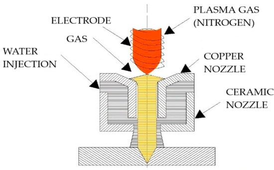 Figure 1. Water injection gun.
 - The use of a specialized device, such as a cutting table, which, with the help of a layer of water, ensures the absorption of the generated microscopic particles suspended in air and, at the same time, faster cooling of the cut base material. Figure 2 illustrates the cutting table.

Figure 2.
Water-bed plasma cutting table: (a) physical assembly; (b) section view.
The cutting table shown in Figure 2 works on the principle of placing the cut material on the metal profiles on the upper part, after which the compressed air is directed or removed to a chamber located at the bottom of the table, causing the water level to rise or fall accordingly. In this way, the piece can be cut at water level, as illustrated in Figure 3a, or below its level, as seen in Figure 3b.
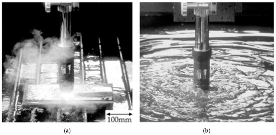
Figure 3.
Water-bed plasma cutting table: (a) at water level; (b) underwater.
2.2. Research Logistics
In the framework of the research logistics used, the authors mention the equipment used for cutting 10 square-shaped pieces with a side of 90 mm: ComCut 31. It is a CNC numerical control cutting machine by the manufacturer Messer Grisheim (Figure 4).
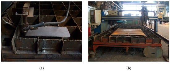
Figure 4.
ComCut 31 CNC cutting machine equipped with (a) plasma cutting torch; (b) oxy-fuel torch.
The machine equipped for cutting with an oxy-gas burner or air plasma installation has the following technical characteristics:
- Cutting path length: 6000 [mm];
- Cutting width: 2200 [mm];
- Thickness of the sheet to be cut: oxy-gas min. 8, max. 120 [mm]; plasma min. 1, max. 30 [mm];
- Positioning speed: 10,000 [mm/min];
- Continuously adjustable cutting speed: yes;
- Cutting path tracking accuracy: 0.1 [mm].
The following CNC functions can be accessed through Omniwin software Version 6.3.5:
- Straight line cutting in coordinates;
- Automatic alignment of the cutting head with respect to the material to be cut;
- Automatic rotation of the cut piece on the Ox and Oy axes;
- Automatic cutting of mirrored parts and parts to scale;
- Library of standard and derived figures;
- Self-diagnostic messages;
- Return to the cutting contour;
- Automatic return to perforation points or to the interruption point of a program;
- Selection of cutting mode/program run (manual, automatic, step-by-step test);
- Cutting gap compensation.
The cutting machine allows the alternative use of the following equipment:
- Oxy-fuel burner model: Messer Grisheim; or
- Plasma source: with air connected to the compressed air network of the workshop;
- Plasma cutting torch fixed on the cutting arm of the machine;
- Cutting electrode;
- Cutting nozzle: Ø1.6/90–120 Amperes;
- High-resolution field emission scanning electron microscope equipped with energy dispersive X-ray analysis (EDS) system;
- Wilson-Wolpert micro durometer, with loads of 0.01–1 kgf.
For a better evacuation of the slag residues from the cutting, the following system was designed by which the water from the settling tank “washes” the cutting tank.
A container for collecting the slag residues from the cutting process was also installed in the settling tank, so that the efficiency of the device increased considerably, a fact also demonstrated by the subsequent measurements we carried out. Some images from the operation of the redesigned device are shown in Figure 5. The settling tank has the dimensions 470 mm (in width) × 720 mm (in length) × 1010 mm (height) and supports a maximum capacity of 290 L of water. It has a dual role: it ensures a lower-temperature water reserve necessary during the cutting operation and stores the cut material ejected in the form of slag from the cut.
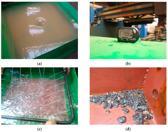
Figure 5.
Water-bed cutting device final version (470 mm in width, 720 mm in length, and 1010 mm in height)—aspects during operation: (a) water level at the beginning of the operation; (b) temperature measurement; (c) sprinkling; (d) slag residues.
In order to monitor the water temperature in the cutting tank, the device was also equipped with a thermometer with an underwater probe.
Once this device was made, the authors moved on to adapting it according to the requirements of the experimental program. The intensive use of the device required the development of several operating and maintenance instructions in order to ensure
- A longer operating life;
- An ecological working environment.
In terms of functionality, after the related work tests, the device improvements were carried out as follows: the closed water circuit was redesigned and enlarged, a water pump with superior characteristics was installed (capable of ensuring a flow rate of 25 L/min), the filter element was replaced with a slag waste collection container placed in the settling tank, and, once the device was optimized, an optimal cutting plan (nesting) was designed using the cutting machine software program.
Related to the cutting parameters, the base material is S355J2 + AR and is 6 mm thick, in accordance to the SR EN 10025/25-2004 standard [51].
As follows, this work will refer to the samples obtained by the plasma cutting processes taking place both within the free atmosphere (in open air) of the metal fabrication workshop and at the lower edge on the water level (in water-bed). The experimental set-up parameters are depicted in Table 2.
Table 2.
Experimental set-up working parameters.
2.3. Experimental Procedure: Analysis of Samples
It is completed or finalized by photographic recording or printing of the macrostructure in the form of macrographs or prints. The overall examination of metallic products (semi-finished or finished products), without or with prior preparation, allows the rapid detection of general or particularly specific defects that occur:
- Compactness defects (cuts, porosities, cracks);
- Structural inhomogeneities (crystalline grains of different sizes, shapes or orientations, etc.);
- Chemical inhomogeneities (segregation of alloying elements, harmful impurities, etc.);
- Inhomogeneities (areas or layers of different materials joined by gluing, welding or plating, deposited electrolytically, etc.);
- Other material or processing defects (coarse non-metallic inclusions, overlaps, decarburization, etc.), as well as aspects of degradation during service (rupture, wear, corrosion, burning, etc.).
The macrostructure is closely correlated with the behavior of the product during subsequent technological operations and, above all, ensures the final physical and mechanical properties during service and therefore the reliability of the product. In metallographic laboratories in the metallurgical, processing, and machine building industries, macroscopic analysis is commonly practiced; this is a method of interphase or final quality control of metal products. Data are obtained on the conditions, character, and quality of previous processing undergone by the metal.
Macroscopic analysis is a method of researching the structure of metallic materials, which can be performed with the naked eye; with a magnifying glass, which can magnify several times; or with a stereomicroscope, at a magnification of up to 50 times, of the outer surface or of specially prepared sections detached from them. To allow a correct, objective, and reproducible classification of macroscopic structures—by product groups and characteristic defects—they are regulated by macrostructural standards (for porosities, segregations, casting, forging, welding, heat treatment defects).
For the macroscopic analysis, the parts with the edge cut by the plasma process in open air (free atmosphere) (samples 1-1 and 1-2), in a water-bed (samples 2-1 and 2-2) and by an oxygen flame (samples 3-1 and 3-2) are presented in Figure 6.
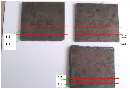
Figure 6.
Samples (90 mm × 90 mm) for microstructural analysis.
The enlarged images of the cut edge are presented, at different sizes, in Figure 7.
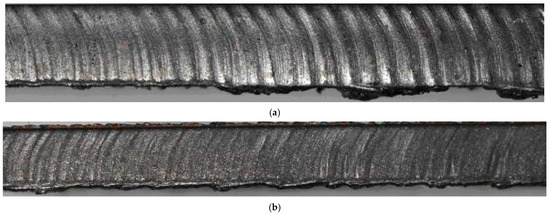
Figure 7.
Macroscopic image of the edge cut (thickness of 6 mm, 10×) in (a) air and (b) water-bed.
In the case of samples cut with plasma in open air, a consistent slag layer is observed at the lower part of the cut edge as well as irregular cutting marks with consistent depth. In the case of samples cut with plasma in a water-bed, a less consistent slag layer is observed at the lower part of the cut edge as well as irregular cutting marks with a smaller depth than in the case of cutting in open air. At the same time, reddish areas are observed due to more pronounced oxidation following contact with the water-bed. In the case of both samples, the appearance of curved cutting marks is observed, which attests to the lagging behind of the plasma jet, even if the working parameters recommended by the manufacturer of the cutting machine and the plasma source have been respected. Microscopic analysis is performed in situations where it is mandatory to also know the results of structural analyses (naval register, aerospace construction, highways, etc.). The choice of the optimal cutting technology is also made depending on the results obtained in this way.
The set of measurements performed before and after the design of the water-bed cutting device have revealed the following effects on the working environment: the final technological version of the water-bed cutting device proved to be efficient, and the device is robust, mobile, flexible, easy to maintain, and can be used with minimal maintenance instructions for a long time, with the development of the optimal cutting plan. In this regard, the optimal working parameters of mechanized cutting were determined, based on the data provided by the cutting equipment manufacturer and our own measurements.
3. Results
The samples illustrated in Figure 6 were cut according to the following configurations:
- a.
- Samples 1-1 and 1-2—by thermal cutting with air plasma, in the free atmosphere (open air) of the workshop;
- b.
- Samples 2-1 and 2-2—by thermal cutting with air plasma, the piece being placed on a water-bed at the bottom;
- c.
- Samples 3-1 and 3-2—by oxygen flame cutting.
The samples were embedded in a phenolic resin and were then prepared metallographically, by grinding, polishing, and chemical etching with Nital 2%. The examination was carried out on one surface perpendicular to the cutting plane.
3.1. Samples 1-1 and 1-2
Microstructural examination with a scanning electron microscope and determination of microhardness revealed the following aspects:
- a.
- The microstructure of the base material, unaffected by the cutting operations, is typical for an unalloyed steel, with a low carbon content, in a plastically deformed + annealed state: equiaxed grains of ferrite and small amounts of pearlite, as seen in Figure 8. The granulation is extremely fine and uniform (average grain diameter 15–16 µm, corresponding to a score of 9 according to ASTM E112). Rarely, non-metallic inclusions (sulfides and silicates) were observed, normal for a steel processed under ordinary conditions. The hardness, determined by the Vickers method with micro loads, was 120–125 HV05.
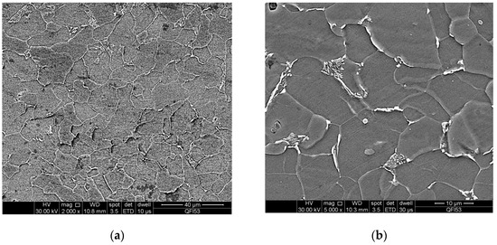 Figure 8. Microstructure of the base material, unaffected by the cutting operations, observed on samples 1-1 and 1-2. Equiaxed grains of ferrite and small amounts (approx. 5%) of lamellar pearlite: (a) ×2000; (b) ×5000.
 - b.
- EDS analysis is used for the chemical characterization of each sample and can also highlight precipitation phenomena, which is the reason for applying this method to the characterization of cut surfaces, as seen in Figure 9.
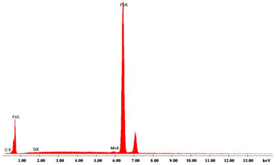 Figure 9. EDS spectrum obtained for sample 1-1, area unaffected by cutting operations. Chemical elements detected: Fe, Mn, Si, and C.
On both samples, the edges corresponding to the exposure to the cutting operations show traces of microstructure modification, at a depth of 0.7–1.0 mm. The modifications consist in the appearance of the phenomenon of partial marginal recrystallization, with the appearance of a new generation of grains, as seen in Figure 10.
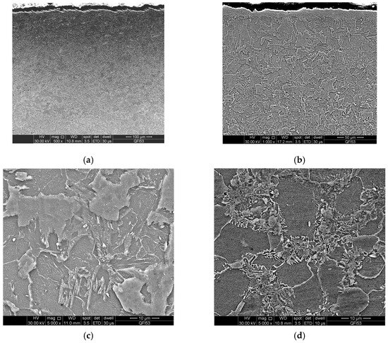
Figure 10.
Samples 1-1 and 1-2: (a) marginal area thermally affected by the cutting operation (general appearance, ×500), observed on sample 1-1; (b) slightly increased granulation, on a marginal area, observed on sample 1-2 (×1000); (c) modified structure, at 100 µm depth, observed on sample 1-1 (×5000); (d) partially recrystallized structure, at 400 µm distance from the cut edge (×5000), observed on sample 1-2.
This fact attests to the accentuated heating of the material, around the austenitic transformation temperature. The microhardness is also slightly affected, with the obtained values decreasing from the edge to the core. See Table 3. The ferrite grains slightly modify their morphology, becoming slightly distorted, and the pearlite has a lamellar appearance with a slight tendency for globulation. Only at a depth of approx. 100 µm is the granulation slightly increased compared to the core, reaching a score of 6–7 according to ASTM E 112.
Table 3.
Microhardness (HV 05 value) of samples 1-1 and 1-2 obtained for various depths.
3.2. Samples 2-1 and 2-2
The microstructural aspects observed on samples 1-1 and 1-2 are also found on samples 2-1 and 2-2, with some particularities, as follows:
- a.
- The base material presents an absolutely identical structure, probably coming from the same batch: very fine grains of ferrite, equiaxes, and very small amounts of lamellar pearlite, as seen in Figure 11. The hardness confirms the material brand and the heat treatment state, being 120–125 HV05.
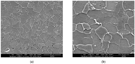 Figure 11. Microstructure of the base material, observed on samples 2-1 and 2-2. Equiaxed grains of ferrite and small amounts (approx. 5%) of lamellar pearlite: (a) ×2000; (b) ×5000.
 - b.
- The modification of the microstructure in the areas thermally affected by cutting is also similar to that observed on the previous samples: partial recrystallization, with the appearance of grains even finer than those of the base material, as well as grain growth to a depth of 100 µm on the edges, in some places even with a martensitic appearance, in the areas where the temperature was higher. A special aspect was observed on sample 2-2, marginally more severely affected, by the appearance of areas of intergranular oxidation and local melting, at a depth of 60–70 µm.
- c.
- The hardness is different, however, with the heat-affected areas registering higher values (230–260 HV05), probably due to the higher cooling rate. See Table 4. Due to the fact that this steel is used for welded structures and the carbon is below 0.2%, it is difficult to harden to martensite, as depicted below. But, the HAZ can reach values of 260 for HV05. See Figure 12 and Figure 13.
Table 4. Microhardness (HV 05 value) of samples 2-1 and 2-2 obtained for various depths.
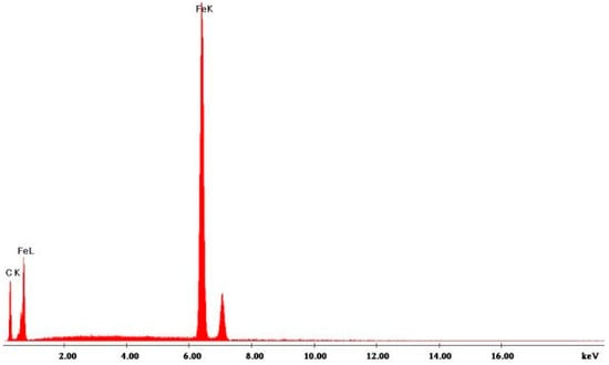 Figure 12. EDS spectrum obtained for sample 2-1. Chemical elements detected: Fe and C.
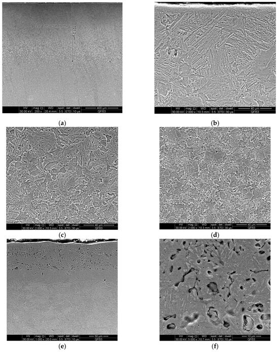 Figure 13. Samples 2-1 and 2-2: (a) marginal area thermally affected at a depth of 0.7 mm, observed on sample 2-1 (×200); (b) marginal structure affected by cutting heating and rapid cooling (×2000)—martensitic structure, with larger grains; (c) transition zone from martensitic to recrystallized structure at a depth of 200 µm from the edge, observed on sample 2-1 (×2000); (d) partially recrystallized microstructure, at a depth of 400 µm from the edge, observed on sample 2-1 (×2000); (e) local melting and intergranular oxidation, observed on sample 2-2 (×1000); (f) detail from the image in (e). Local melting observed on sample 2-2 (×5000).
3.3. Samples 3-1 and 3-2
Different microstructural and hardness aspects were observed on samples 3-1 and 3-2, as follows:
- a.
- The base material presents a slightly different structure compared to the samples described previously. Although the structure is still ferrite–pearlitic, a higher amount of pearlite was observed in the ferritic matrix. This may be due to a higher carbon content. Being a surface cutting operation, the transformation of ferrite into pearlite occurs through carbon precipitation but does not reach the parameters for the formation of martensite. The hardness in the core is also slightly higher, around 150–160 HV05. The content of non-metallic inclusions, distributed along the direction of plastic deformation of the material, is also higher.
- b.
- Oxygen flame cutting generated thermal damage to the material at much greater depths: 2 mm on sample 3-1 and 4–5 mm on sample 3-2. The heat-affected zones are visible even macroscopically on the samples attacked with Nital 2%. Marginally, the structure is even martensitic, with large grains, reaching sizes of 200 µm, with coarse platelets that gradually decrease in size, until the core. Also marginally, plastic deformations of the material were observed, forming areas with a strictly local fiber structure.
- c.
- The microhardness in the marginal areas is non-uniform. If on sample 3-1 values between 187 and 226 HV05 were recorded, on sample 3-2 values of 250–260 HV05 were also obtained. See Figure 14 and Figure 15 and Table 5.
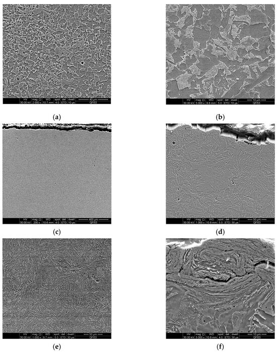 Figure 14. Microstructure of samples: (a) 3-1; (b) 3-2, in the core. Equilateral grains of ferrite and lamellar pearlite (approx. 30%). Marginal structure affected by heating, observed on sample 3-1. Large grains of ferrite and martensite: (c) ×200; (d) ×1000. (e) Marginal area thermally affected 1 mm from the surface, observed on sample 3-2. Mixture of martensite, ferrite, and pearlite (×1000). (f) Local, marginal plastic deformation observed on sample 3-2 (×5000).
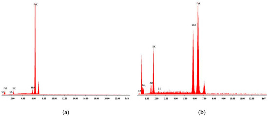 Figure 15. EDS spectra obtained on two types of inclusions, observed on samples 3-1 and 3-2: (a) manganese iron sulfide; (b) aluminum silicate, nucleated on an iron manganese sulfide.
Table 5. Microhardness (HV 05 value) of samples 3-1 and 3-2 obtained for various depths.
Figure 15. EDS spectra obtained on two types of inclusions, observed on samples 3-1 and 3-2: (a) manganese iron sulfide; (b) aluminum silicate, nucleated on an iron manganese sulfide.
Table 5. Microhardness (HV 05 value) of samples 3-1 and 3-2 obtained for various depths.
3.4. Results Overview
In the tests presented previously, the authors have also taken into consideration oxyfuel cutting as a classic method and compared plasma cutting in air to plasma cutting in a water-bed, which was shown to reduce emissions such as dust and sound. From the analysis of 6 mm carbon steel sample parts cut mechanically with plasma in free atmosphere and in the water-bed, the following data are summarized in Table 6.
Table 6.
Comparative analysis of results.
4. Conclusions
This paper presents a comprehensive experimental study that aims to characterize the surface of cut pieces from a structural steel S355J2 + AR plate, both with plasma in the designed water-bed and in open air, considering, in addition, the resulting differences to oxygen fuel cutting, a classic cutting procedure, in order to be applied for welding structures.
Macroscopic analysis: Following the macroscopic comparative analyses of the cut edge profiles for the two plasma cutting procedures, their interpretation reveals that the slag layer is less consistent at the lower part of the cut edge as well as the irregular cutting marks with a smaller depth compared to open-air cutting. At the same time, reddish areas are observed due to more pronounced oxidation following contact with the water-bed.
Microscopic analysis: The microscopic analysis has led to the following comparative remarks for the two plasma cutting procedures: the granulation is preserved, as ferrite and pearlite grains were observed to have the same size both in the base material zone (15–16 µm for ferrite and small amounts for pearlite) and in the HAZ (01–0.7 mm, with transformations in the austenitic temperature zone), while for oxygen flame cutting, the grains were observed to have an extended size in the HAZ (4–5 mm, with martensitic structure and large grains).
Hardness: In the HAZ, the following values were obtained for plasma cutting: 172–147 in HV05 values in open air, and 260–172 in HV05 values in the water-bed. These values are similar to the ones obtained for oxygen flame cutting: 255–144 in HV05 values.
Technical–economic aspects: A water-bed cutting device was designed and manufactured by the authors and, in its construction, materials from demolitions (sheet metal, pipe, angle iron) were used; thus, a significant reduction in production costs was obtained. When being used, the device is mobile, flexible, and versatile, as it can be easily moved from one workstation to another. At the same time, the device was designed in order to be robust and easy to maintain. In this regard, the subassemblies subject to wear and tear can be easily and quickly replaced. The microstructure of the cut surfaces is not influenced by the proposed and designed device, but it is part of the research logistics. Previous experimental research has shown that during intensive cutting regimes, the water-bed overheats and loses its efficiency. Therefore, to ensure a volume of water at the appropriate temperature, the cutting tank was connected to a so-called decanter.
Health and environmental impacts: By monitoring residues and noxious emissions and by improving cutting parameters, a clean and efficient method addressed to cutting procedures in the industrial environment was proposed herein. Its impact on the environment was shown to be positive, as initial measurements have revealed significant reductions in PM10 concentrations (in terms of maximum value) from more than 10 mg/m3 to less than 5 mg/m3 at the water level, while the sound level was kept at an acceptable level, not exceeding the attention limit of 90 dB.
Author Contributions
Conceptualization, T.M.-P. and A.O.; Methodology, T.M.-P. and M.M.-P.; Validation, T.M.-P. and A.O.; Formal analysis, M.M.-P.; Investigation, M.M.-P. and A.O.; Resources, T.M.-P.; Data curation, M.M.-P. and A.O.; Writing—original draft, T.M.-P.; Writing—review & editing, M.M.-P.; Visualization, M.M.-P.; Supervision, T.M.-P. All authors have read and agreed to the published version of the manuscript.
Funding
This research received no external funding.
Institutional Review Board Statement
Not applicable.
Informed Consent Statement
Not applicable.
Data Availability Statement
Data is contained within the article.
Conflicts of Interest
The authors declare no conflict of interest.
References
- Igwemezie, V.; Shamir, M.; Mehmanparast, A.; Ganguly, S. A review of LTT welding alloys for structural steels: Design, application and results. J. Adv. Join. Process. 2022, 5, 100110. [Google Scholar] [CrossRef]
- Cheng, C.; Xie, X.; Yu, M.; Wang, T. A CDM-based constitutive model for structural steel considering ULCF damage accumulation. J. Constr. Steel Res. 2025, 232, 109646. [Google Scholar] [CrossRef]
- Xu, F.; Zhao, J.; Zhou, X.; Yun, X.; Liu, J.-Z.; Okazaki, T. Long-term strain ageing effects on low-carbon structural steels. J. Constr. Steel Res. 2025, 231, 109579. [Google Scholar] [CrossRef]
- Uszball, S.; Knobloch, M. Post-fire structural material behaviour of high- and ultra-high-strength steels–Experimental study and aids for assessment for further use and potential reuse after fires. Constr. Build. Mater. 2024, 443, 137742. [Google Scholar] [CrossRef]
- Klusák, J.; Seitl, S. Very high cycle fatigue tests of high strength steels S355 J0 and S355 J2. Procedia Struct. Integr. 2019, 17, 576–581. [Google Scholar] [CrossRef]
- Ferreño, D.; Portilla Carral, J.; Lacalle Calderón, R.; Álvarez, J.A.; Gutiérrez-Solana, F. Development and experimental validation of a simplified Finite Element methodology to simulate the response of steel beams subjected to flame straightening. Constr. Build. Mater. 2017, 137, 535–547. [Google Scholar] [CrossRef]
- Cortés, R.; Garrido, M.A.; Rico, A.; Múnez, C.J.; Poza, P.; Martos, A.M.; Dosta, S.; Cano, I.G. Effect of processing conditions on the mechanical performance of stainless steel cold sprayed coatings. Surf. Coat. Technol. 2020, 394, 125874. [Google Scholar] [CrossRef]
- Das, R.; Sivaswamy, G.; Lalvani, H.; Singh, A.P. Fracture toughness and microstructural analysis of rotary friction welded S355J2 and SS316L steels for critical applications. J. Adv. Join. Process. 2024, 10, 100244. [Google Scholar] [CrossRef]
- Graebner¨, M.; Giese, M.; Lorenz, S.; Treutler, K.; Schroepfer¨, D.; Wesling, V.; Kannengiesser, T. Wear resistance of modified NiMoCrSi claddings in relation to the resulting surface machinability via ultrasonic-assisted milling. Wear 2025, 571, 205830. [Google Scholar] [CrossRef]
- Bendikiene, R.; Ciuplys, A.; Sertvytis, R.; Surzhenkov, A.; Tkachivskyi, D.; Viljus, M.; Traksmaa, R.; Antonov, M.; Kulu, P. Wear behaviour of Cr3C2–Ni cermet reinforced hardfacings. J. Mater. Res. Technol. 2020, 9, 7068–7078. [Google Scholar] [CrossRef]
- Milz, M.P.; Wirtz, A.; Abdulgader, M.; Biermann, D.; Tillmann, W.; Walther, F. Influence of twin wire arc spraying and machine hammer peening on the corrosion fatigue of ZnAl4 coatings on S355 J2C + C substrate. Procedia Struct. Integr. 2022, 42, 830–837. [Google Scholar] [CrossRef]
- Zorc, B.; Bernetič, J.; Nagode, A. Effects of welding residual stresses and phosphorus segregation on cleavage delamination fracture in thick S355 J2 G3+N steel plate. Eng. Fail. Anal. 2014, 40, 8–14. [Google Scholar] [CrossRef]
- Ulewicz, R.; Szataniak, P.; Novy, F.; Trsko, L.; Bokuvka, O. Fatigue characteristics of structural steels in the gigacycle region of loading. Mater. Today Proc. 2017, 4, 5979–5984. [Google Scholar] [CrossRef]
- Stranghöner, N.; Jungbluth, D. Fatigue Strength of Marked Steel Components. Procedia Eng. 2015, 133, 282–293. [Google Scholar] [CrossRef][Green Version]
- Straße, A.; Üstündağ, Ö.; Gumenyuk, A.; Rethmeier, M. LMD coatings as filler material for laser beam welded 30 mm thick plates. Procedia CIRP 2020, 94, 293–297. [Google Scholar] [CrossRef]
- Wang, J.; Wong, W.C.K. A study of abrasive waterjet cutting of metallic coated sheet steels. Int. J. Mach. Tools Manuf. 1999, 39, 855–870. [Google Scholar] [CrossRef]
- Irsel, G.; Güzey, B.N. Comparison of laser beam, oxygen and plasma arc cutting methods in terms of their advantages and disadvantages in cutting structural steels. J. Phys. Conf. Ser. 2021, 2130, 012022. [Google Scholar] [CrossRef]
- Harničárová, M.; Valíček, J.; Zajac, J.; Hloch, S.; Čep, R.; Džubáková, I.; Tofil, S.; Hlaváček, P.; Klich, J.; Čepová, L.; et al. Techno-economical comparison of cutting material by laser, plasma and oxygen. Ekon. Usporedba Rezanja Mater. Pomoću Lasera Plazme i Kisika 2012, 19, 813–817. Available online: https://core.ac.uk/download/pdf/10672942.pdf (accessed on 1 June 2025).
- Jagadish; Gupta, K. Abrasive Water Jet Machining of Engineering Materials; Springer International Publishing: Berlin/Heidelberg, Germany, 2020. [Google Scholar] [CrossRef]
- Gullu, A.; Atici, U. Investigation of the effects of plasma arc parameters on the structure variation of AISI 304 and St 52 steels. Mater. Des. 2006, 27, 1157–1162. [Google Scholar] [CrossRef]
- Jiang, X.-Y.; Hu, J.; Jiang, S.-L.; Wang, X.; Zhang, L.-B.; Li, Q.; Lu, H.-P.; Yin, L.-J.; Xie, J.-L.; Deng, L.-J. Effect of high-enthalpy atmospheric plasma spraying parameters on the mechanical and wear resistant properties of alumina ceramic coatings. Surf. Coat. Technol. 2021, 418, 127193. [Google Scholar] [CrossRef]
- Luțcanu, M.; Cimpoeșu, N.; Istrate, B.; Coteață, M.; Manole, V.; Știrbu, I.; Dimitriu, F. Analyze of Cutting Effect on Ceramic Coated Steels. Procedia Manuf. 2020, 47, 808–811. [Google Scholar] [CrossRef]
- Luțcanu, M.; Coteață, M.; Bernevig, M.A.; Nechifor, C.D.; Cazacu, M.M.; Paraschiv, P.; Istrate, B.; Bădărău, G.; Sandu, I.G.; Cimpoeșu, N. Obtaining and Analyzing the Al2O3-ZrO2 Ceramic Layers on Metallic Substrate. Arch. Metall. Mater. 2021, 479–485. [Google Scholar] [CrossRef]
- Krajcarz, D. Comparison Metal Water Jet Cutting with Laser and Plasma Cutting. Procedia Eng. 2014, 69, 838–843. [Google Scholar] [CrossRef]
- Akkurt, A. Surface properties of the cut face obtained by different cutting methods from AISI 304 stainless steel materials. Indian J. Eng. Mater. Sci. 2009, 16, 373–384. Available online: https://nopr.niscpr.res.in/bitstream/123456789/7293/1/IJEMS%2016(6)%20373-384.pdf (accessed on 2 June 2025).
- Olah, A.; Machedon-Pisu, M.; Machedon-Pisu, T. Research on Mechanized Plasma Gouging of Weldable Construction Steels. Coatings 2024, 14, 1502. [Google Scholar] [CrossRef]
- Bhuvenesh, R.; Abdul Manan, M.S.; Norizaman, M.H. The Study of Surface Roughness and MRR of Mild Steel Using Manual Plasma Arc Cutting Machining. Adv. Mater. Res. 2012, 576, 3–6. [Google Scholar] [CrossRef]
- Bini, R.; Colosimo, B.M.; Kutlu, A.E.; Monno, M. Experimental study of the features of the kerf generated by a 200A high tolerance plasma arc cutting system. J. Mater. Process. Technol. 2008, 196, 345–355. [Google Scholar] [CrossRef]
- Colombo, V.; Concetti, A.; Ghedini, E.; Rotundo, F.; Sanibondi, P.; Boselli, M.; Dallavalle, S.; Gherardi, M.; Nemchinsky, V.; Vancini, M. Advances in Plasma Arc Cutting Technology: The Experimental Part of an Integrated Approach. Plasma Chem. Plasma Process. 2012, 32, 411–426. [Google Scholar] [CrossRef]
- Colombo, V.; Concetti, A.; Ghedini, E.; Dallavalle, S.; Fazzioli, R.; Vancini, M. Optimization of plasma arc cutting of mild steel thin plates. In Proceedings of the 2008 IEEE 35th International Conference on Plasma Science, Karlsruhe, Germany, 15–19 June 2008. [Google Scholar] [CrossRef]
- Nemchinsky, V.A. Two phases of droplet evaporation during plasma arc spraying: Reply to Chen’s comment about the ‘rocket’ effect under conditions of thermal plasma spraying. J. Phys. D Appl. Phys. 2007, 40, 4098–4100. [Google Scholar] [CrossRef]
- Ramakrishnan, S.; Shrinet, V.; Polivka, F.B.; Kearney, T.N.; Koltun, P. Influence of gas composition on plasma arc cutting of mild steel. J. Phys. D Appl. Phys. 2000, 33, 2288–2299. [Google Scholar] [CrossRef]
- Sember, V.; Mašláni, A.; Křenek, P.; Heinrich, M.; Nimmervoll, R.; Pauser, H.; Hrabovský, M. Spectroscopic Characterization of a Steam Arc Cutting Torch. Plasma Chem. Plasma Process. 2011, 31, 755–770. [Google Scholar] [CrossRef]
- Ebadian, M.A.; Dua, S.K.; Guha, H. Size Distribution and Rate of Production of Airborne Particulate Matter Generated During Metal Cutting; Hemispheric Center for Environmental Technology: Pittsburgh, PA, USA, 2001. [CrossRef][Green Version]
- Zhou, Q.; Li, H.; Liu, F.; Guo, S.; Guo, W.; Xu, P. Effects of Nozzle Length and Process Parameters on Highly Constricted Oxygen Plasma Cutting Arc. Plasma Chem. Plasma Process. 2008, 28, 729–747. [Google Scholar] [CrossRef]
- Pandya, D.M. A Review Paper on Study and optimization of Process Parameter in Plasma arc Cutting. Int. J. Res. Appl. Sci. Eng. Technol. 2019, 7, 537–542. [Google Scholar] [CrossRef]
- Rzeźnikiewicz, A. Cost comparison between oxyfuel and plasma cutting low alloy steel. J. Achiev. Mater. Manuf. Eng. 2014, 63, 81–85. Available online: http://jamme.acmsse.h2.pl/vol63_2/6324.pdf (accessed on 3 June 2025).
- Sharma, A.; Yadava, V. Experimental analysis of Nd-YAG laser cutting of sheet materials–A review. Opt. Laser Technol. 2018, 98, 264–280. [Google Scholar] [CrossRef]
- Kanyilmaz, A. The problematic nature of steel hollow section joint fabrication, and a remedy using laser cutting technology: A review of research, applications, opportunities. Eng. Struct. 2019, 183, 1027–1048. [Google Scholar] [CrossRef]
- He, Y.; Xie, H.; Ge, Y.; Lin, Y.; Yao, Z.; Wang, B.; Jin, M.; Liu, J.; Chen, X.; Sun, Y. Laser Cutting Technologies and Corresponding Pollution Control Strategy. Processes 2022, 10, 732. [Google Scholar] [CrossRef]
- Akkurt, A. The effect of cutting process on surface microstructure and hardness of pure and Al 6061 aluminium alloy. Eng. Sci. Technol. Int. J. 2015, 18, 303–308. [Google Scholar] [CrossRef]
- Majolagbe, S.; Abioye, A.; Akinluwade, K.; Adesina, O.; Adetunji, A. Radiation Effects: Recommendations for Safe Plasma/Flame Cutting Operation. J. Sci. Res. Rep. 2015, 6, 237–242. [Google Scholar] [CrossRef]
- Radovanovic, M. Abrasive Waterjet Cutting Cost. Nonconventional Technologies Review. No.1. Available online: https://www.academia.edu/39248632/Nonconventional_Technologies_Review_No_1_2007_97_ABRASIVE_WATERJET_CUTTING_COST (accessed on 4 June 2025).
- Aloke, R.; Girish, V.; Scrutton, R.F.; Molian, P.A. A model for prediction of dimensional tolerances of laser cut holes in mild steel thin plates. Int. J. Mach. Tools Manuf. 1997, 37, 1069–1078. [Google Scholar] [CrossRef]
- Luţcanu, M.; Munteanu, C.; Kicsi, G.; Roman, A.-M.; Croitoru, C.G.; Prisecariu, B.A.; Cazacu, M.M.; Ştirbu, I.; Chicet, D.L.; Cimpoeşu, N. Analysis of water jet cutting of metal-ceramic elements made through atmospheric plasma spraying technique. Mater. Today Proc. 2023, 72, 550–553. [Google Scholar] [CrossRef]
- Lutcanu, M.; Istrate, B.; Coteata, M.; Chicet, D.L.; Ionita, I.; Paraschiv, C.; Stirbu, I.; Badarau, G.; Cimpoesu, N. Structural aspects and chemical analyses on cutting process of metallic-ceramic materials. IOP Conf. Ser. Mater. Sci. Eng. 2021, 1037, 012033. [Google Scholar] [CrossRef]
- Mitchell, B.R.; Demian, S.A.R.; Korkolis, Y.P.; Kinsey, B.L. Experimental comparison of material removal rates in abrasive waterjet cutting and a novel droplet stream technique. Procedia Manuf. 2020, 48, 586–592. [Google Scholar] [CrossRef]
- Hlaváčová, I.M.; Sadílek, M.; Váňová, P.; Szumilo, Š.; Tyč, M. Influence of steel structure on machinability by abrasive water jet. Materials 2020, 13, 4424. [Google Scholar] [CrossRef]
- Natarajan, Y.; Murugesan, P.K.; Mohan, M.; Liyakath Ali Khan, S.A. Abrasive Water Jet Machining process: A state of art of review. J. Manuf. Process. 2020, 49, 271–322. [Google Scholar] [CrossRef]
- Ivan, P.; Dejan, M.; Bogdan, N.; Ivan, S. Modeling and Optimization of Cut Quality Responses in Plasma Jet Cutting of Aluminium Alloy EN AW-5083. Materials 2021, 14, 5559. [Google Scholar] [CrossRef] [PubMed]
- SR EN 10025/25-2004; Standard for Rolled Steels EN 10025-2. Asociația de Standardizare din România (ASRO): Bucharest, Romania, 2004.
Disclaimer/Publisher’s Note: The statements, opinions and data contained in all publications are solely those of the individual author(s) and contributor(s) and not of MDPI and/or the editor(s). MDPI and/or the editor(s) disclaim responsibility for any injury to people or property resulting from any ideas, methods, instructions or products referred to in the content. |
© 2025 by the authors. Licensee MDPI, Basel, Switzerland. This article is an open access article distributed under the terms and conditions of the Creative Commons Attribution (CC BY) license (https://creativecommons.org/licenses/by/4.0/).