Article

Chip Flow Direction Modeling and Chip Morphology Analysis of Ball-End Milling Cutters

Key Laboratory of Advanced Manufacturing and Intelligent Technology, Ministry of Education, Harbin University of Science &Technology, Harbin 150080, China
*
Author to whom correspondence should be addressed.
Coatings 2025, 15(7), 842; https://doi.org/10.3390/coatings15070842
Submission received: 27 June 2025 / Revised: 14 July 2025 / Accepted: 16 July 2025 / Published: 18 July 2025
(This article belongs to the Special Issue Cutting Performance of Coated Tools)

Abstract

Ball-end milling cutters are normally used for complex surface machining. During the milling process, the tool posture and cutting parameters of the ball-end milling cutters have a significant impact on chip formations and morphological changes. Based on the Cutter Workpiece Engagement (CWE) model, this study establishes a chip flow model for ball-end milling cutters with consideration of the tool posture variation. The machining experiments of Ti-6Al-4V with a 15° inclined plane and different feed directions were carried out. The influence mechanism of time-varying tool posture on chip formation was systematically investigated. The results reveal an interaction between the chip flow direction and the cutting velocity direction. The included angle between the chip flow directions at the maximum and minimum contact points in the CWE area affects the degree of chip curling, with a smaller angle leading to weaker curling. This research provides a theoretical foundation for the optimization of posture parameters of ball-end milling cutters and expounds on the influence of the chip flow angle on chip deformation.

1. Introduction

Titanium alloys exhibit complex material properties, leading to significant machining difficulties. During the machining process, a tool posture with a negative rake angle will deteriorate the cutting conditions and reduce machining quality [1]. The tool posture parameters can alter the cutting speed, thereby influencing chip formation and the surface quality of the workpiece [2,3]. Optimizing the right tool posture during machining can improve machining quality and chip morphology [4,5,6]. Some scholars [7,8,9,10] have carried out cutting experiments on tool posture to explore the influence of tool posture on cutting parameters. Through cutting experiments, they found that the machined surface quality is correlated with both tool posture and the chip formation process. Liang et al. [11] conducted a finish milling experiment on TC17 titanium alloy using a cemented carbide ball-end mill, with the workpiece inclined at 30°. The study revealed that a horizontal upward feed direction can improve chip morphology.
Numerous scholars have conducted in-depth research on the mechanisms of chip formation and control, with a primary focus on the mechanisms governing chip morphology evolution and the trajectory of chip flow.
First, several scholars have investigated the mechanisms of chip morphology transformation from diverse perspectives. Liu et al. [12] systematically summarized the sawtooth chip characteristics of titanium alloys fabricated via traditional and additive manufacturing methods. The effects of different cutting methods, such as turning, milling, and drilling, on chip morphology were analyzed through experiments. It was pointed out that factors such as tool geometry and cutting speed are closely related to chip shape and size. Aydın et al. [13] discovered via simulation that the numerical sawtooth frequency increases with rising cutting speed, particularly at conventional high-speed regimes. Ullah et al. [14] observed through turning experiments on Ti-6Al-4V that plastic deformation on the chip back surface increases with rising cutting speed. Nevertheless, they did not clearly reveal the influence law of cutting speed on chip curling morphology. Zhu et al. [15] analyzed the formation mechanism of serrated chips in low-speed cutting of Ti-6Al-4V, demonstrating that it was closely associated with fluctuations in cutting speed. Duc et al. [16] performed hard turning tests on 90CrSi tool steel, demonstrating that when the undeformed chip thickness falls below a critical value, plastic chip flow occurs. The chip formation process and material lateral flow were found to primarily depend on the workpiece material hardness and cutting speed. Yang et al. [17] developed an analytical model for sawtooth chip deformation, derived the quantitative relationship between chip formation characteristic parameters and cutting speed, and revealed that chip deformation increases with rising cutting speed. The studies primarily focus on the role of cutting speed and parameters in chip morphology evolution but overlook the influence of chip flow direction on chip formation.
In the research field of chip flow direction, many scholars have carried out studies using finite element simulation, machining experiments, and mathematical models. Tounsi et al. [18] compared three models using finite element simulation, demonstrating that an increase in tool nose radius leads to a substantial rise in thrust force, with chip flow primarily governed by geometric constraints and frictional effects. Through analytical modeling and finite element validation, Li et al. [19] demonstrated that the mutual constraints of tool nose discrete elements dictate the overall chip flow direction, identifying the principal deviation angle, cutting depth, and inclination angle as the key control parameters for chip flow angle. Fazlali et al. [20] proposed that the shear band rolling mechanism is central to chip segmentation and flow dynamics, showing that different cutting techniques result in diverse tool–chip contact configurations and segmentation characteristics. Leksycki et al. [21] established through experimental research on specific cutting speeds and feed ranges that arch-shaped loose chips or serrated chips would be produced. They also indicated that increasing the rake angle could reduce the friction between chips and the rake face, decrease the chip flow angle, and more readily form continuous chips. Selvakumar, S., et al. [22] discovered in turning experiments that a larger cutting edge radius (e.g., 70 μm) yields thinner yet bulkier chips, with the chip flow angle increasing from 45° to 75°. When the cutting edge radius exceeds 59 μm, both the sawtooth height and thermal instability exhibit significant increases, while the chip core thickness decreases. These studies demonstrate that cutting speed and rake face parameters influence chip flow direction and alter chip morphology. Meanwhile, the real-time variation in chip flow angle is challenging to measure experimentally, posing difficulties for data analysis.
To predict chip flow direction, researchers have proposed several models, including geometric, upper bound, and mechanistic models. The earliest geometric model was proposed by Stabler [23], who postulated that in free oblique cutting, the chip flow angle equals the inclination angle. And some geometric relation-based chip flow direction models that take the nose radius into account have been proposed. Colwell [24] assumed that the chip flows in the vertical direction of the equivalent cutting edge, and for turning tools with zero rake angle, the chip flow angle was determined using a geometric method. The geometric model proved efficient and reliable for constructing simple structures, yet it required integration with other methods when addressing complex dynamic problems. Young et al. [25] incorporated an additional deformation zone within the nose radius, computed the local cutting angle using upper and lower limit angles via geometric modeling, and concluded that the edge inclination angle served as the key parameter for controlling chip flow direction. They further proposed that the chip flow angle is influenced by both tool inclination angle and cutting depth. Ghosh et al. [26] developed three chip flow models, demonstrating that chip flow direction aligns with the resultant force direction. Their distribution is dynamically governed by the effective principal cutting edge angle and inclination angle, whereas the tool nose radius influences the degree of deviation by altering the cutting-edge contact length. Aksu et al. [27] experimentally analyzed key parameters in oblique cutting, revealing that the Stabler rule exhibits significant errors at high inclination angles. Their findings showed that orthogonal data transformation methods provide more accurate predictions of chip flow angle. Matsumura et al. [28] confirmed that modifying the local blade angle and spiral angle can direct axial chip discharge and reduce radial interference. Koné et al. [29] established a chip flow angle model linked to chip flow velocity, revealing that the tool’s rake angle and blade inclination angle influence the chip flow angle by altering the chip removal direction. It was further demonstrated that optimizing blade geometry contributes to the mitigation of chip removal resistance. The mechanism model comprehensively considered the tool parameters and could describe the dynamic process without a lot of calculation.
Building on the above methods, numerous scholars have achieved notable advancements in related research domains. Nevertheless, the majority of existing studies center on modeling chip flow angles and analyzing chip morphology with consideration of milling parameters. The modeling of chip flow angle still faces the challenge that traditional modeling approaches struggle to cope with the dynamic angle variations in ball-end milling cutters in the multi-pose cutting process. The influence mechanism of tool posture on chip flow direction remains unclear.
This study integrates the differential analysis method for spiral cutting edges with a dynamic tool posture change model, aiming to predict the chip flow direction during ball-end milling of titanium alloy inclined planes. The main contents are as follows:
(1)
The chip flow model, considering the posture changes in ball-end milling cutters, is developed.
(2)
Based on the CWE model, the influence of chip flow direction on chip morphology is analyzed.
(3)
Using experimental methods with varied feed directions, the influence of chip flow direction on chip geometry and the chip formation principle are confirmed, and a tool posture adjustment strategy is proposed.

2. Materials and Methods

2.1. Materials

The workpiece material utilized in this experiment is Ti-6Al-4V, whose chemical composition is detailed in Table 1. The titanium alloy material is a square blank with a size of 100 mm × 100 mm × 50 mm. In terms of metallographic structure, Ti-6Al-4V alloy usually exhibits a dual-phase structure composed of α phase and β phase. The α phase is a close-packed hexagonal (HCP) crystal structure, and the β phase is a body-centered cubic (BCC) crystal structure. Ti-6Al-4V, a widely used structural material with high strength and good corrosion resistance, features complex machinability and factor-dependent chip formation. This makes it suitable for chip flow modeling and morphological analysis, serving as a typical sample to explore the cutting mechanisms of difficult-to-machine materials and advance related industrial technologies. Titanium alloys exhibit notable reactivity with cutting tool materials, coupled with low thermal conductivity, leading to inherently poor machinability. During the cutting process, temperature elevation in the cutting zone triggers repeated adhesion between the chip and tool. The impact of material properties on machining processes has been examined in another scholarly work [30]. The present study, by contrast, restricts its scope to an analysis of the effects exerted by macroscale factors on chip formation. The key mechanical and thermal properties of the material are tabulated in Table 2.

2.2. Chip Flow Model of Ball-End Milling Cutter
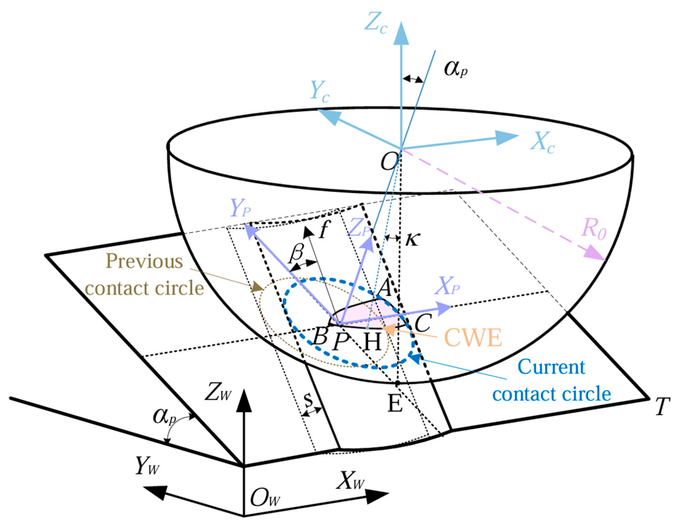
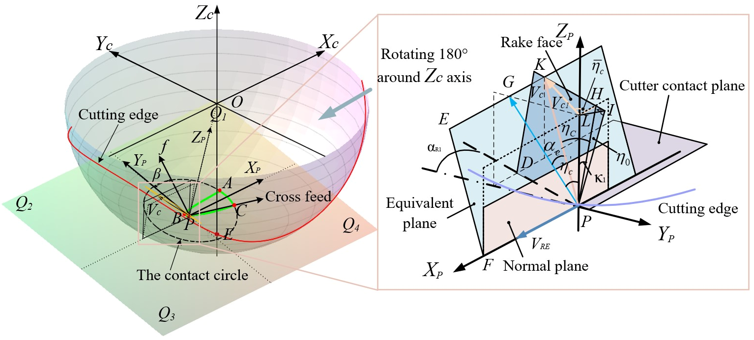
2.2.1. CWE Model

During the ball-end milling cutter process, the relative position between the cutter and workpiece continuously varies, leading to dynamic changes in the tool–workpiece contact relationship. To gain deeper insights into the relationship between tool cutting speed and chip flow velocity, a CWE model for ball-end milling cutter is first developed via geometric analysis and rigid body transformation. The CWE model [32] for three-axis milling of inclined planes is illustrated in Figure 1.
The CWE area is surrounded by three curves: AB, AC and BC. P is the cutter contacts point, which is located on the curve BC and makes contact with the machined surface. Among these, BC represents the intersection curve between the tool’s rotational surface and the machined surface at the transition of the current tool path. AB is the intersection curve between the tool’s rotational surface and the previously machined surface, while AC represents the intersection curve between the tool’s rotational surface and the surface to be machined, visually depicting the tool’s cutting trajectory into the workpiece. The feed direction of the tool is f, and the angle between it and the coordinate axis YP is the feed direction angle β. s is the cutting width, and αP is the machining angle. Let H denote an arbitrary reference point on the boundary of the contact area, κ denote the axial position angle of this point, and E represent the tool nose. The expressions of the boundary AB, AC, and BC of the contact area are as follows:
X A B = N . R . sin κ s . cos β R sin κ 2 R sin κ s 2 . sin β Y A B = N . R . sin κ s . sin β + R sin κ 2 R sin κ s 2 . cos β . cos α p + R cos κ . sin α p Z A B = N . R . sin κ s . sin β + R sin κ 2 R sin κ s 2 . cos β . sin α p + R cos κ . cos α p
X B C = N . R . sin κ . cos β Y B C = N . R . sin κ . sin β . cos α p + R . cos κ . sin α p Z B C = N . R . sin κ . sin β . sin α p R . cos κ . cos α p
X A C = N . R 2 R e 2 R sin κ 2 R sin κ s 2 . cos β R sin κ 2 R sin κ s 2 . sin β Y A C = N . R 2 R e 2 R sin κ 2 R sin κ s 2 . sin β + R sin κ 2 R sin κ s 2 . cos β . cos α p e R . sin α p Z A C = N . R 2 R e 2 R sin κ 2 R sin κ s 2 . sin β + R sin κ 2 R sin κ s 2 . cos β . sin α p + e R . cos α p

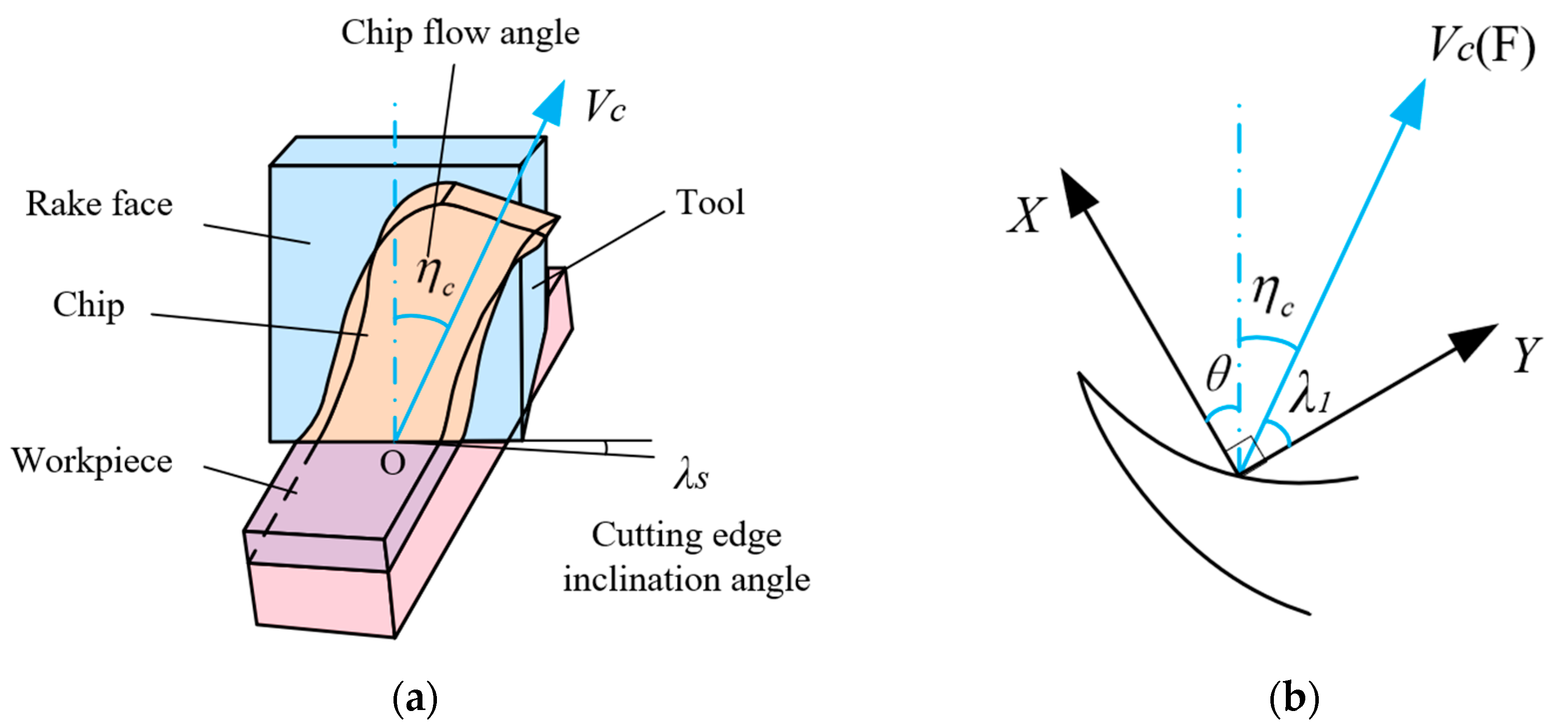
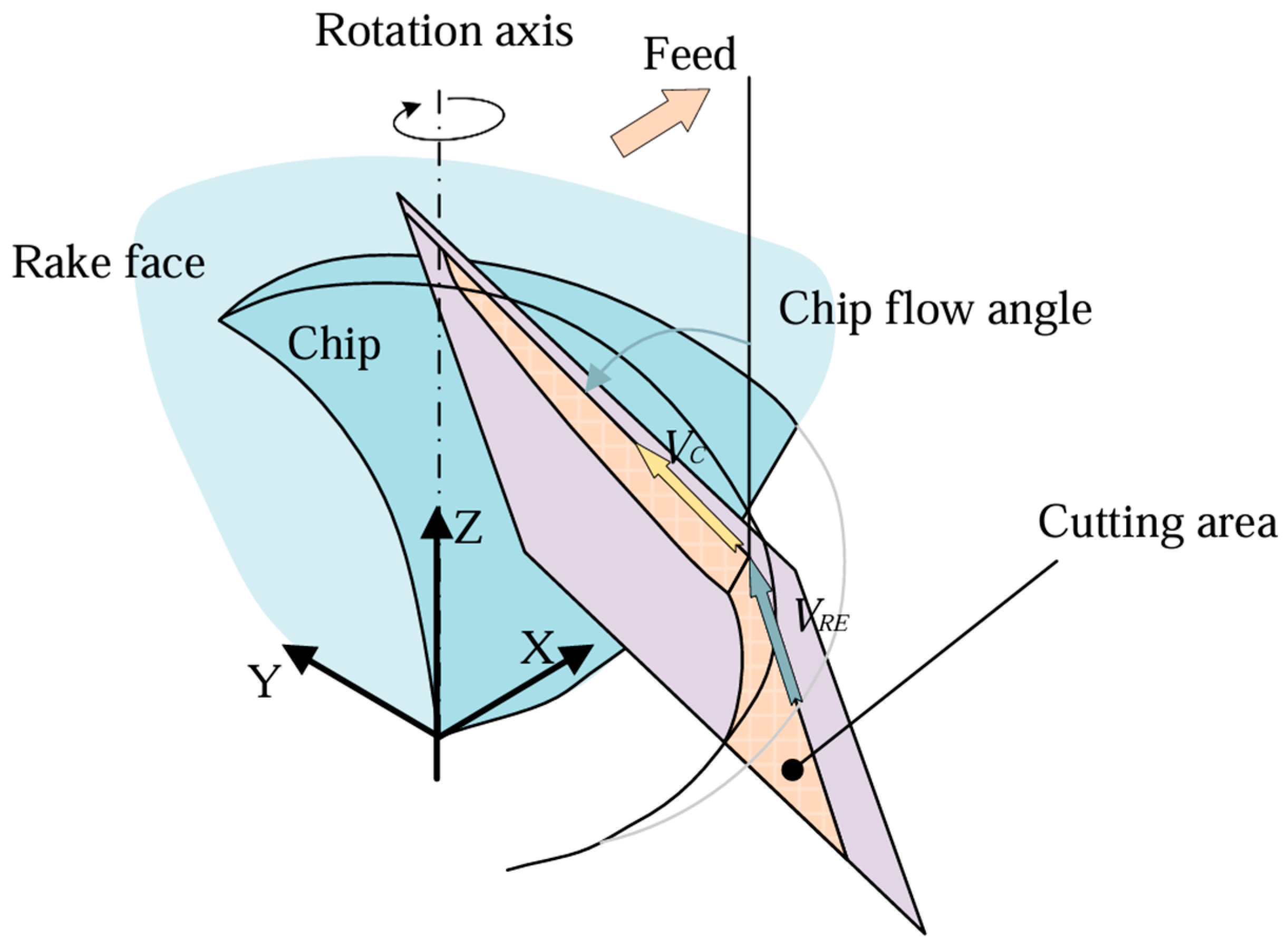
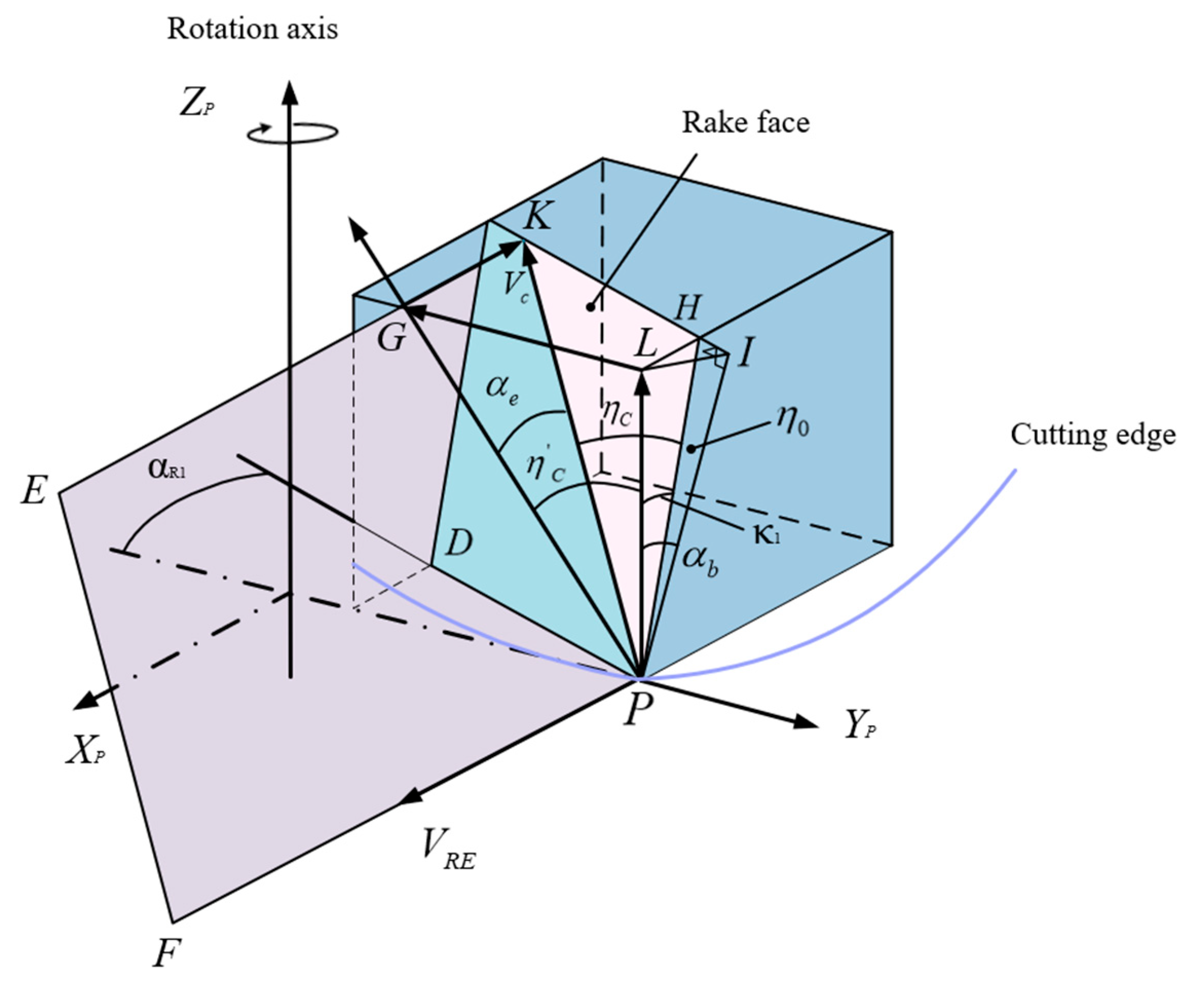
2.2.2. Analysis and Modeling of Chip Flow Direction

In the milling process, the tool contact area (CWE) changes with the tool feed direction. The variation in chip flow direction is attributed to the discrepancy in the tool cutting edge contact position across different postures. To simplify this process, the cutting edge is discretized into a series of infinitesimal cutting edge elements based on the principle of differentiation. According to the oblique cutting theory, the chip flow direction is illustrated in Figure 2a. In the figure, λ S denotes the tool edge inclination angle, and the angle between the chip flow direction and the cutting edge normal is defined as the chip flow angle ηc. The velocity in this direction is the chip flow velocity Vc. The cutting process of each infinitesimal cutting edge element can be approximated as an oblique cutting process, thus providing a theoretical foundation for the subsequent development of the chip flow angle model.
To investigate the relationship between cutting speed and chip flow velocity at various tool positions, Young et al. (1993) [25] developed a cutting model for the undeformed contact chip region at the tool tip, as illustrated in Figure 2b. Based on Coulomb’s friction law, it is assumed that the direction of the frictional force F on each infinitesimal element coincides with the direction of the chip flow velocity Vc. The relationship between cutting speed and chip flow velocity is revealed, and the final expression is shown in Formula (4). Let η c denote the chip flow angle, λ1 represent the angle between the chip flow velocity Vc on the rake face and the Y-axis (perpendicular to the tool tip), which is related to the cutting speed, and θ signifies the projection of the main cutting edge angle onto the rake face.
η c = π 2 θ λ 1
Thus, from the above analysis, it can be inferred that there is a definite correlation between chip flow velocity Vc and cutting speed VRE. In this section, the relationship between tool posture and cutting speed is first analyzed, followed by an investigation into the effect of tool posture on chip flow velocity Vc. Finally, a chip flow angle model for ball-end milling cutters is established. Figure 3 illustrates the chip flow direction on the rake face of the ball-end milling cutter, with the cutting speed VRE and chip flow velocity Vc characterized in the cutting plane.
When ball-end milling cutter contacts an inclined plane, the local helix angle varies with the axial angle κ of any point on the cutting edge, as expressed by Equation (5). β 1 denotes the effective helix angle, which varies with the machining inclination angle α P as shown in Equation (6), where β 0 is the tool helix angle and R is the radius of the ball-end milling cutter.
β 0 ( κ ) = arctan R sin κ R ( 1 cos κ )
β 1 = arccos R 4 R 4 + R 2 R 2 cos 2 α P 2 tan 2 β 0
The cutting speed VRE is the vector sum of the tool rotation line velocity Vr and the feed speed Vf, as illustrated in Figure 4. The included angle ϕ is the acute angle formed by the cutting speed VRE and tool rotation linear velocity Vr, which can be calculated using Equations (7)–(10). n is the cutter rotational speed. Zn is teeth number. And fz is the feed per tooth.
V r = 2 π n R sin κ 1000 cos β 1
V f = n z n f z 60
V R E = ( ( V r + V f sin β ) 2 + ( V f cos β ) 2 )
ϕ = arccos ( V f cos β V R E )
When the machining inclination angle αP is 15°, the variation in the included angle ϕ with the feed direction β, and axial angle κ is shown in Figure 5. It can be seen from the figure that the direction of cutting speed is obviously influenced by the tool posture. Overall, the cutting speed direction exhibits an irregular curved surface, indicating that both angles exert a significant influence on it. The influence of these two angles cannot be overlooked in the subsequent study of chip flow direction. When the axial angle κ is 0, it is found that the included angle ϕ changes linearly and is determined by a distinct protrusion point. Notably, the tangential velocity Vr at the tool nose is zero during tool tip engagement with the workpiece, so that the included angle variation depends solely on the feed direction.
Figure 6 illustrates the cutting model at the cutting edge contact point. A cutting model incorporating cutting speed VRE and chip flow velocity Vc is established on the rake face PDKH. The chip flow angle ηc is the angle KPH on the rake face, the projected angle ηc is the angle GPL, and αe is the angle GPK, as defined by Equation (11):
α e = sin 1 { sin ( η 0 + η c ) sin α R 1 + cos ( η 0 + η c ) tan κ 1 cos α b cos 2 α R 1 }
αR satisfies Equation (12), where j = 1, 2, 3, …, n. αR1 and κ1 denote the radial and axial angles of the inclined plane PDKH, respectively, as defined by Equations (13) and (14).
α R = tan β 1 cot ( κ 2 ) + ( j 1 ) 2 π Z n
α R 1 = α R + ϕ
κ 1 = tan 1 ( tan α b / cos α R 1 )
αb is the rake face inclination angle LPI in a plane perpendicular to the rake face and containing line PI. It is related to the axial and radial rake angles, as defined by Equation (15):
α b = tan 1 ( tan κ cos α R )
η 0 is the angle HIP, calculated using Equation (16), where PH represents the projection of the vertical axis PI onto the rake face.
η 0 = cos 1 ( cos κ 1 / cos α b )
Chips are the product of material extrusion and shearing on the rake face of the tool. The cutting speed direction of each point of the cutting edge of ball-end milling cutter is different from the rake angle, which leads to the three-dimensional characteristics of the chip flow direction. The variation in cutting direction during ball-end milling affects chip formation and chip shape evolution. To further explore the chip shape change mechanism, the chip flow velocity Vc is projected onto the tool contact plane, as illustrated in Figure 7. The chip flow angle η ¯ c on the cutting plane is defined as the acute angle between the contact plane projection Vc1 of chip flow velocity Vc and cutting velocity VRE. To facilitate further research, the feed direction of the ball-end milling cutter is divided into four intervals (Q1, Q2, Q3, Q4) in the contact plane, corresponding to four directions, namely upper right, upper left, lower left, and lower right, respectively. When the feed direction angle β ∈ [−90°, 0°), f lies in Q1 (upper right); when β ∈ [0°, 90°), f is in Q2 (upper left); when β ∈ [90°, 180°), f is in Q3 (lower left); and when β ∈ [−180°, −90°), f is in Q4 (lower right). The cutting geometry analysis in any direction in the Q1 interval is shown in Figure 7. The tool contact point P is located on the curve BC in direct contact with the machined surface.
η c (angle GPL) can be calculated from ηc using Equation (17). The chip flow angle η ¯ c (angle KLH) is expressed by Equation (18):
η c = cos 1 { cos α b cos ( η 0 + η c ) / cos α e }
η ¯ c = π 2 arcsin sin α e 1 cos 2 α e cos 2 η c
Chip formation is influenced by multiple factors, such as the tool–workpiece contact relationship. On the contact plane, the region can be partitioned into the processed area and unmachined area. A correlation may exist between chip flow direction and these areas. The chip flow velocity and cutting speed on the contact plane exhibit a strong directional correlation, with their orientations toward the machined area illustrated in Figure 8. The cutting speed direction in the diagram is consistent with the X-axis direction.
The dynamic variation in chip flow angle η ¯ c on the cutting plane, at a fixed inclination angle of 15°, with changes in the feed direction angle β and the axial angle κ, is illustrated in Figure 9. As shown in the figure, the chip flow angle η ¯ c and the above two angles indeed exhibit a strong correlation, consistent with the preceding analysis. In the region where the axial angle κ is 0°, the chip flow angle undergoes a sudden change when the feed direction angle β is −112.5°. This change mirrors the trend of cutting speed VRE shown in Figure 5. This research trend is consistent with the findings of prior scholars, thereby verifying the effectiveness of the model. It was found that there is a distinction between positive and negative chip flow angles in the remaining region. According to theoretical analysis, the tool rotation motion is defined as the positive direction, and η ¯ c is positive when the chip flow velocity is within Q1 and Q2 intervals and is negative otherwise. This distinction reveals the relative positional relationship between chip flow direction and cutting speed direction, which could be a factor influencing chip morphology. To investigate the correlation between chip flow direction and chip morphology, experiments with varying feed directions were conducted.

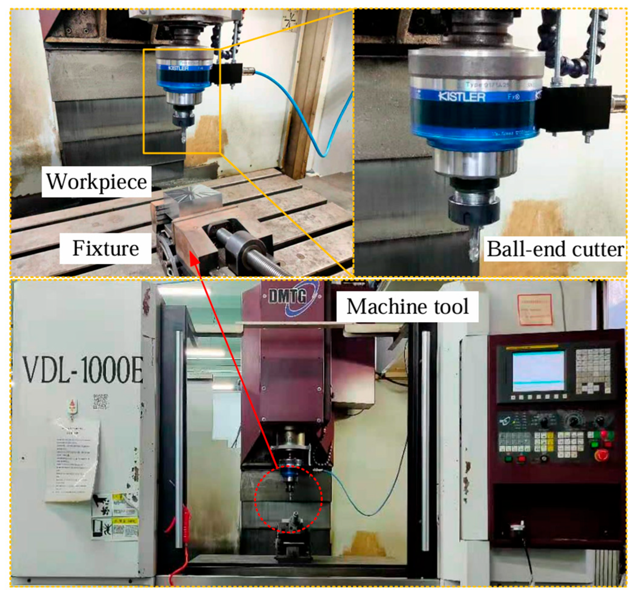
2.3. Experimental Set-Up

The cutting experiment was conducted for 15° inclined surface machining on a three-axis CNC machine tool (VDL-1000E, Dalian Machine Tool Group, Dalian, China), and a square blank with a size of 100 mm × 100 mm × 50 mm was selected. The workpiece was machined by down-milling, and the toolpaths are shown in Figure 10. The feed directions β were selected with 16 angles within the range of (−180°,180°], which are [−90°, −67.5°, −45°, −22.5°] in the Q1 range, [0°, 22.5°, 45°, 67.5°] in the Q2 range, [90°, 112.5°, 135°, 157.5°] in the Q3 range and [±180°, −157.5°, −135°, −112.5°] in the Q4 range. All paths are machined from the outside of the workpiece to the center of the workpiece by dry cutting. The tilting fixture was used to install the workpiece, and the inclination angle of the fixture was adjusted to 15°. Chip samples were collected at the conclusion of each cutting pass, and post-test chip photography was performed using an industry camera.The processing parameters of the experiment are given in Table 3, and the equipment and instruments used are shown in Figure 11.
Table 3. Experimental parameters.
n (r/min)fz (mm/tooth)e (mm)s (mm) β 0 (°) α P (°)
40000.080.30.155015
Figure 11. Instruments and equipment used.
Coatings 15 00842 g011

3. Results

In the down milling process, the chip flow angle, as a key process parameter, has a significant influence on chip morphology transformation.
Based on the positive/negative characteristics of the chip flow angle η ¯ c on the cutting contact plane, this section selects several characteristic angles for systematic analysis. When the chip flow angle η ¯ c is positive or negative, specific representative angles are selected for analytical research. Considering that the chip flow direction is essentially a synthesis process of multi-dimensional velocity vectors, this study decomposes and analyzes the chip flow velocities at the extreme positions of the tool on the contact plane (i.e., the instantaneous velocities at the lowest and highest points of contact, denoted as V1 and V2, respectively, which can be obtained from Figure 9) to investigate the morphological changes during chip formation.
When the chip flow angle η ¯ c is positive, the transformation of chip morphology is as depicted in Figure 12. Within the angular range from 45° to 112.5°, the degree of chip curling deformation exhibits a gradient decreasing trend. As can be seen from Table 4, in the 45° feed direction, the chip flow velocity V1 at the lowest cutting contact point and the velocity V2 at the highest point exhibit a distinct intersecting trend in the positive direction, with an included angle of 4.784°. They represent the starting and ending points of a single cutting process, as well as the initiation and termination of chip formation. The intersection of the chip flow velocity directions may subject the chip to external extrusion during formation, leading to curl deformation. Compared with the chips in the 45°direction, the curvature of chips in the 67.5° direction decreases. Meanwhile, the included angle between the positive direction chip flow velocities V1 and V2 reduces to 2.557°, a 50% decrease. In the 90° and 112.5° directions, chips show an overall straight morphology. At this point, the directions of chip flow velocities V1 and V2 are in a dispersed state in the positive direction, and the chips are stretched by both sides during the chip evacuation process, leading to a reduction in the degree of curl.
It can be inferred that the chip flow velocity directions at the two extreme points during chip formation have a significant influence on chip morphology. When there is an intersection trend between the two in the positive direction, the resultant force acting on the chip during its formation process squeezes the chip, causing the final chip morphology to be in a curled state. When the two are almost parallel in the positive direction, the squeezing effect of the resultant force on the chip decreases, and the chip bending is weakened. When the two form a divergent angle in the positive direction, the resultant force no longer exerts a squeezing effect on the chip, causing a significant reduction in the degree of chip curling.
Through the analysis of the chip shapes in the figure, it was found that chip morphology with different feed directions. To further explore the chip forming mechanism, this study analyzes it from the perspective of chip flow velocity direction and the geometric relationship of cutting contact. From the cutting-edge line perspective, the length of the edge line intersecting with the cutting contact area continuously increases in the direction from 45° to 112.5°, and the shape swept by the tool edge gradually matches the CWE area. This may cause the chip morphology to increasingly approach the shape of the CWE area. With the change in feed direction, chip flow velocities start to point toward the unprocessed area, which can obstruct chip evacuation.
When the chip flow angle η ¯ c is negative, the change in chip morphology is as shown in Figure 13. In these directions, it can be observed that the chip morphology displays distinct curling. From the direction of −45° to −112.5°, the degree of chip curling deformation continues to intensify, and even spiral chips appear in the direction of −112.5°. First, analyzing the chip flow velocities, as can be seen from Table 5, in the −45° direction, the chip flow velocity V1 at the lowest point of the tool and the chip flow velocity V2 at the highest point showed a trend of intersection in the positive direction, and the included angle formed by the two is 4.334°. Based on the above analysis, it can be concluded that during chip formation, the chip is slightly squeezed by the external resultant force, leading to a slightly curled state. In the −90° direction, the included angle formed by the chip flow velocity V1 at the tool’s lowest point and the chip flow velocity V2 at the highest point in the positive direction is 4.989°, which starts to increase compared to the −45° direction. At this stage, the curling degree of the chip morphology is more pronounced than that in the −45° direction. In the −112.5° direction, the included angle between the chip flow velocity V2 at the highest point and the cutting velocity direction reaches 88.778°, approaching a vertical state. In this direction, the actual magnitude of the chip flow velocity V1 can be considered 0°. The chip flow velocity on one side approaches 0°, causing the chips to continuously rotate around the tool tip, thereby resulting in severe chip evacuation difficulties. The chip morphology shows severe curling and obstructed evacuation, which correlated with change in cutting speed discussed earlier. This confirms that cutting speed affects chip flow velocity, thereby influencing chip morphology.
From the perspective of the chip flow velocity direction and the cutting contact geometric relationship, in the −45° direction, the chip flow velocity is farther away from the unprocessed area compared to the 112.5° direction, and the length of the intersection line between the cutting edge line and the CWE area is significantly smaller. At this point, the chip morphology consists of small pieces with a certain degree of curling, but no chip adhesion occurs. In the −90° direction, the variation in the length of the intersection line between the cutting edge and the CWE area is insignificant. The chip flow velocity direction starts to approach the unprocessed area, and the degree of chip curling intensifies. It is particularly noteworthy that at a feed direction of −112.5°, some chip flow velocities point toward the unprocessed area, and the length of the intersection line between the cutting edge and the CWE area is greater than that in the −90° direction. Multiple chips are observed to be stacked and distributed, interconnected at the central part, eventually forming a spiral chip structure. In the −135° feed direction, the length of the intersection line between the cutting edge and the CWE area is the shortest, and the chip flow velocity direction starts to move away from the unprocessed area. The chip size reaches the minimum, with a low degree of curling but increased fragmentation.
We also pay attention to the research of other scholars. Sonawane, H. A., et al. [33] proposed that the width and thickness of the chip are affected by the tool attitude. Matsumura, T., et al. [34] studied the relationship between the chip flow angle and the cutting force. This paper conducts a comprehensive analysis of the impact of tool posture on the chip flow angle and chip morphology, with the conclusions being consistent with those in the literature.

4. Conclusions

In this study, an analytical prediction model for the chip flow direction of a ball-end milling cutter is proposed, which is based on the inclined plane cutter-workpiece engagement (CWE) and the discretization and differentiation of the cutting edge. The model’s effectiveness is verified through experiments, and the influence of chip flow direction on chip formation is analyzed, leading to the following conclusions:
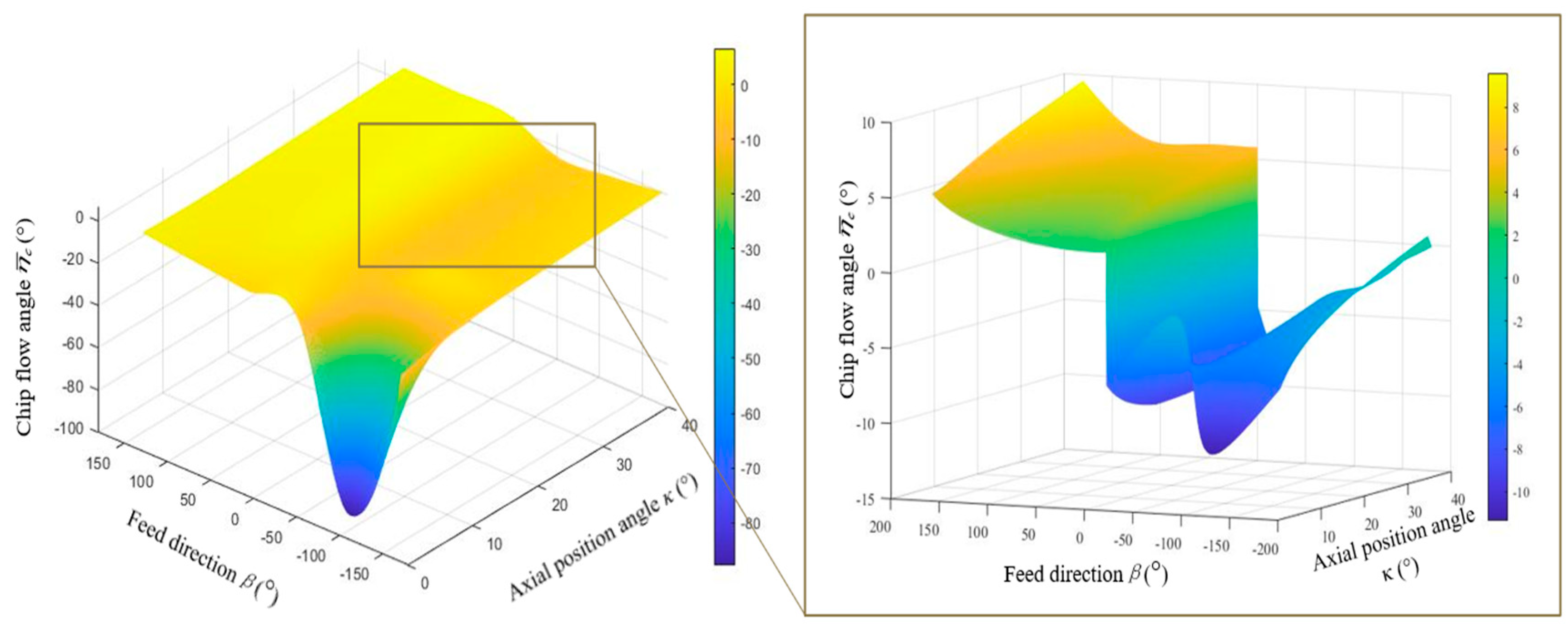
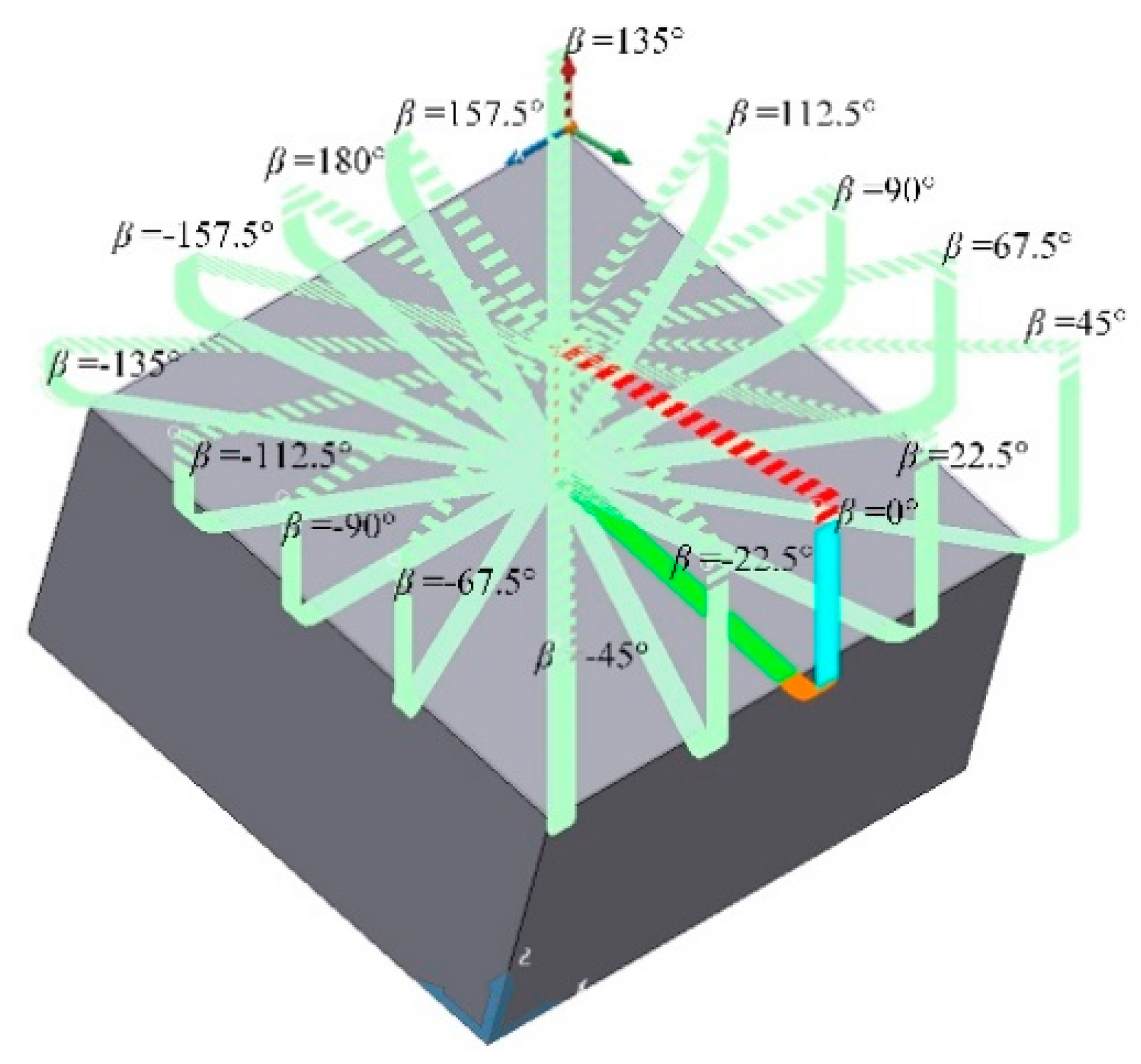
  • A model for the chip flow direction of ball-end milling cutters is established. The theoretical relationship between the cutting velocity and the chip flow velocity on the contact surface is analyzed. It is found that the chip flow direction is influenced by the feed direction, and the chip flow direction changes greatly in the feed direction of −112.5.
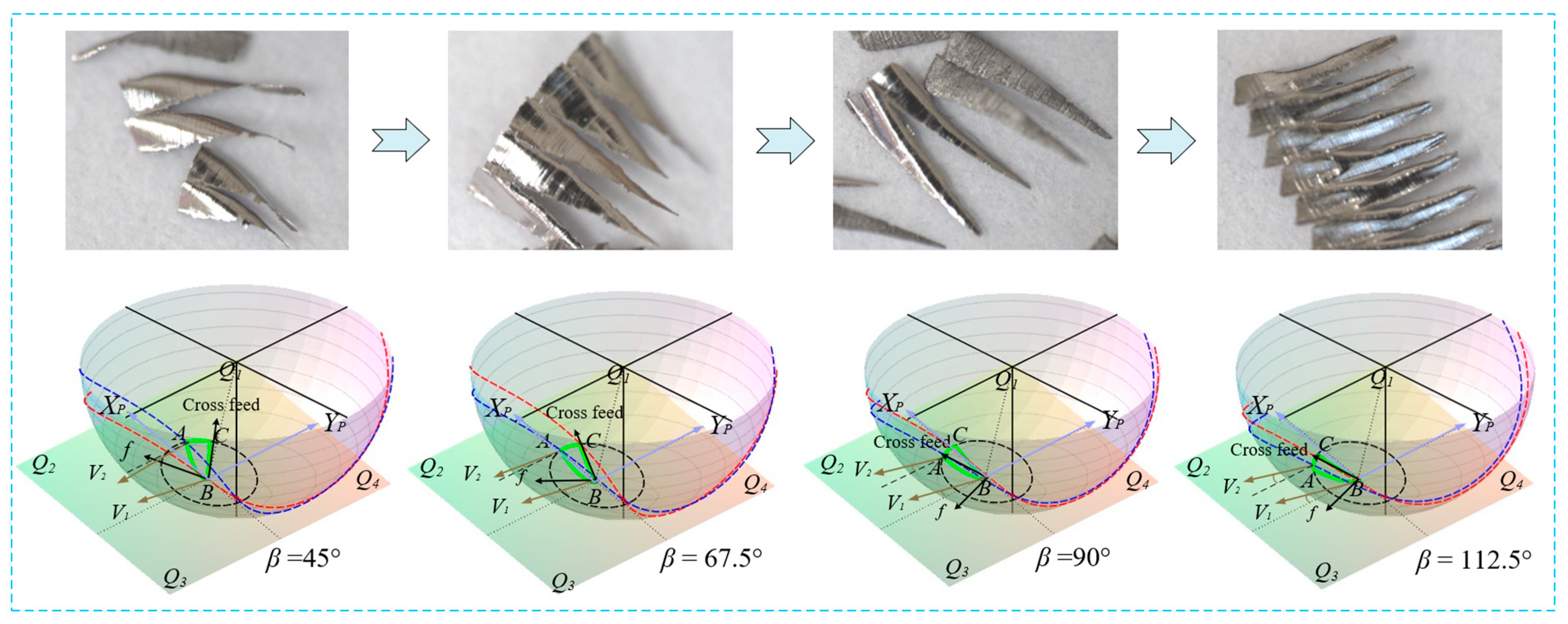
  • The directions of chip flow and cutting speed are core factors affecting chip morphology. The degree of chip curling is influenced by the direction of chip flow velocity. When the chip flow velocities at the two extreme positions form an acute angle, the chip tends to curl. When they do not intersect, the chip shape remains straight.
  • In the engineering practice of down-milling titanium alloys, the feed direction is restricted to the Q2 and Q3 intervals (i.e., the upper-left or lower-left directions), while minimizing tool tip engagement with the contact area. This approach can improve chip evacuation conditions and reduce the risk of material adhesion.
This study mainly analyzes the chip formation mechanism from a macro perspective. In the future, we will consider the influence of the microstructure of the machined material (such as the distribution of α and β phases in Ti-6Al-4V, the phase volume fraction boundaries, and the morphological dimensions) on chip formation.

Author Contributions

S.Z.: Conceptualization, Methodology, Software, Writing—Original draft preparation; A.Z.: Data curation, Resources, Writing—Review and Editing, Funding acquisition, Project administration; X.Z.: Writing—Review and Editing; M.H.: Writing—Review and Editing; B.L.: Writing—Review and Editing. All authors have read and agreed to the published version of the manuscript.

Funding

This research was funded by National Natural Science Foundation of China (grant number 52205461) and Natural Science Foundation Project of Heilongjiang Province (LH2024E081).

Institutional Review Board Statement

Not applicable.

Informed Consent Statement

Not applicable.

Data Availability Statement

The original contributions presented in this study are included in the article. Further inquiries can be directed to the corresponding author.

Conflicts of Interest

The authors declare no conflicts of interest.

Abbreviations

The following abbreviations are used in this manuscript:
OXcYcZcTool coordinate system
OwXwYwZwProcessing coordinate system
PXpYpZpTool contact coordinate system
fTool feed direction
βFeed direction angle
κ1Inclined axial position angle
RTool radius
eCutting depth
κAxial position angle
sTool path stepover
VcChip flow velocity
λ S Blade inclination angle
αpMachining inclination angle
FFrictional force
θProjection of main cutting edge angle
V1Lowest chip flow velocity
VRECutting speed
β 0 , β 1 Cutting tool helix angle and the effective helix angle
A, B, CIntersection points of CWE boundaries
VrTool rotation linear velocity
ϕThe included angle between cutting speed and tool rotation linear velocity
NSpindle speed
znTooth number
fzFeed per tooth
CWECutter workpiece engagement
PCutter contact point
VfFeed speed
η c ,   η c ,   η ¯ c Chip flow angle; YZ plane projection chip flow angle; projection chip flow angle of contact plane
αR, αR1Axial position angle; inclined axial position angle
V2Highest chip flow velocity

References

  1. Zhao, Z.; Wang, S.; Wang, Z.; Liu, N.; Wang, S.; Ma, C.; Yang, B. Interference-and chatter-free cutter posture optimization towards minimal surface roughness in five-axis machining. Int. J. Mech. Sci. 2020, 171, 105395. [Google Scholar] [CrossRef]
  2. Chen, X.; Zhao, J.; Li, Y.; Han, S.; Cao, Q.; Li, A. Investigation on ball end milling of P20 die steel with cutter orientation. Int. J. Adv. Manuf. Technol. 2012, 59, 885–898. [Google Scholar] [CrossRef]
  3. Shen, X.; Zhang, D.; Tan, L. Effects of cutter path orientations on milling force, temperature, and surface integrity when ball end milling of TC17 alloy. Proc. Inst. Mech. Eng. Part B J. Eng. Manuf. 2021, 235, 1212–1224. [Google Scholar] [CrossRef]
  4. Shi, K.; Liu, N.; Wang, S.; Ren, J. Effect of tool path on cutting force in end milling. Int. J. Adv. Manuf. Technol. 2019, 104, 4289–4300. [Google Scholar] [CrossRef]
  5. Tan, L. Effects of tool wear on machined surface integrity during milling of Inconel 718. Int. J. Adv. Manuf. Technol. 2021, 116, 2497–2509. [Google Scholar] [CrossRef]
  6. Luo, M. Improving tool life in multi-axis milling of Ni-based superalloy with ball-end cutter based on the active cutting edge shift strategy. J. Mater. Process. Technol. 2018, 252, 105–115. [Google Scholar] [CrossRef]
  7. Ali, R.A.; Mia, M.; Khan, A.M.; Chen, W.; Gupta, M.K.; Pruncu, C.I. Multi-Response Optimization of Face Milling Performance Considering Tool Path Strategies in Machining of Al-2024. Materials 2019, 12, 1013. [Google Scholar] [CrossRef] [PubMed]
  8. Koklu, U.; BasmaciI, G. Evaluation of Tool Path Strategy and Cooling Condition Effects on the Cutting Force and Surface Quality in Micromilling Operations. Metals 2017, 7, 426. [Google Scholar] [CrossRef]
  9. Hadi, M.A. Comparison between Up-milling and Down-milling Operations on Tool Wear in Milling Inconel 718. Procedia Eng. 2013, 68, 647–653. [Google Scholar] [CrossRef]
  10. García-Barbosa, J.A.; Arroyo-Osorio, J.M.; Córdoba-Nieto, E. Influence of tool inclination on chip formation process and roughness response in ball-end milling of freeform surfaces on Ti-6Al-4V alloy. Mach. Sci. Technol. 2017, 21, 121–135. [Google Scholar] [CrossRef]
  11. Ginting, A.; Nouari, M. Experimental and numerical studies on the performance of alloyed carbide tool in dry milling of aerospace material. Int. J. Mach. Tools Manuf. 2006, 46, 758–768. [Google Scholar] [CrossRef]
  12. Liu, D.; Ni, C.; Wang, Y.; Zhu, L. Review of serrated chip characteristics and formation mechanism from conventional to additively manufactured titanium alloys. J. Alloys Compd. 2024, 970, 172573. [Google Scholar] [CrossRef]
  13. Aydin, M. Numerical study of chip formation and cutting force in high-speed machining of Ti-6Al-4V bases on finite element modeling with ductile fracture criterion. Int. J. Mater. Form. 2021, 14, 1005–1018. [Google Scholar] [CrossRef]
  14. Ullah, I.; Zhang, S.; Zhang, Q.; Wang, R. Numerical investigation on serrated chip formation during high-speed milling of Ti-6Al-4V alloy. J. Manuf. Process. 2021, 71, 589–603. [Google Scholar] [CrossRef]
  15. Zhu, X.; Shi, J.; Liu, Y.; Jiang, Y.; Zhou, B.; Zhao, X. Study on formation mechanism of serrated chip of Ti-6Al-4V titanium alloy based on shear slip theory. Int. J. Adv. Manuf. Technol. 2022, 122, 1353–1365. [Google Scholar] [CrossRef]
  16. Duc, T.M.; Ngoc, T.B.; Tuan, N.M.; Trang, D.T.H.; Long, T.T. A study on mechanisms of saw-tooth chip formation in hard turning under hybrid nanofluid-assisted MQL environment. Adv. Mech. Eng. 2024, 16, 16878132241289286. [Google Scholar] [CrossRef]
  17. Yang, Q.; Liu, Z.; Wang, B. Characterization of chip formation during machining 1045 steel. Int. J. Adv. Manuf. Technol. 2012, 63, 881–886. [Google Scholar] [CrossRef]
  18. Tounsi, N.; El-wardany, T. Finite Element Analysis of the Effects of Process Representations on the Prediction of Residual Stresses and Chip Morphology in the Down-Milling of Ti6Al4V: Part I: Milling of Small Uncut Chip Thicknesses in the Micrometer Range with Finite Cutting Edge Radius. J. Manuf. Sci. Eng. 2022, 144, 011010. [Google Scholar] [CrossRef]
  19. Li, B.; Zhang, R.; Qi, W.; Li, B. Analytical prediction of chip flow direction in cylindrical turning considering rounded edge effect. J. Manuf. Process. 2023, 101, 1234–1245. [Google Scholar] [CrossRef]
  20. Fazlali, M.; Ponga, M.; Jin, X. Predictive model of chip segmentation in machining of high-strength metallic alloys. J. Mater. Process. Technol. 2022, 308, 117723. [Google Scholar] [CrossRef]
  21. Leksycki, K.; Maruda, R.W.; Feldshtein, E.; Wojciechowski, S.; Habrat, W.; Gupta, M.K.; Krolczyk, G.M. Evaluation of tribological interactions and machinability of Ti6Al4V alloy during finish turning under different cooling conditions. Tribol. Int. 2023, 189, 109002. [Google Scholar] [CrossRef]
  22. Selvakumar, S.J.; Raj, D.S. Machinability analysis during finish turning Ti6Al4V with varying cutting edge radius. Mater. Manuf. Process. 2024, 39, 144–160. [Google Scholar] [CrossRef]
  23. Stabler, G.V. The Fundamental Geometry of Cutting Tools. Proc. Inst. Mech. Eng. 1951, 165, 14–26. [Google Scholar] [CrossRef]
  24. Colwell, L.V. Predicting the Angle of Chip Flow for Single-Point Cutting Tools. J. Fluids Eng. 1954, 76, 199–203. [Google Scholar] [CrossRef]
  25. Young, H.T.; Liao, Y.S.; Yang, Y.C.; Mathew, P. Predicting the chip flow for nose radius tools under oblique machining conditions. J. Chin. Inst. Eng. 1993, 16, 825–834. [Google Scholar] [CrossRef]
  26. Ghosh, T.; Paul, S.; Paul, S. Modeling and experimental verification of chip flow deviation in oblique cutting. Mach. Sci. Technol. 2018, 22, 99–119. [Google Scholar] [CrossRef]
  27. Aksu, B.; Çelebi, C.; Budak, E. An experimental investigation of oblique cutting mechanics. Mach. Sci. Technol. 2016, 20, 495–521. [Google Scholar] [CrossRef]
  28. Matsumura, T.; Shirakahi, T.; Usui, E. Analysis of cutting process with roughing end mill. Int. J. Mater. Form. 2009, 2, 555–558. [Google Scholar] [CrossRef]
  29. Koné, F.; Czarnota, C.; Haddag, B.; Nouari, M. Modeling of velocity-dependent chip flow angle and experimental analysis when machining 304L austenitic stainless steel with groove coated-carbide tools. J. Mater. Process. Technol. 2013, 213, 1166–1178. [Google Scholar] [CrossRef]
  30. Zhang, A.; Yue, C.; Liu, X.; Liang, S.Y. Study on the Formation Mechanism of Surface Adhered Damage in Ball-End Milling Ti6Al4V. Materials 2021, 14, 7143. [Google Scholar] [CrossRef] [PubMed]
  31. Mhamdi, M.B.; Boujelbene, M.; Bayraktar, E.; Zghal, A. Surface integrity of titanium alloy Ti-6Al-4 V in ball end milling. Phys. Procedia 2012, 25, 355–362. [Google Scholar] [CrossRef]
  32. Zhang, A.; Liu, X.; Yue, C.; Li, R.; Liang, S.Y.; Wang, L. Velocity effect sensitivity analysis of ball-end milling Ti-6Al-4 V. Int. J. Adv. Manuf. Technol. 2022, 118, 3963–3982. [Google Scholar] [CrossRef]
  33. Sonawane, H.A.; Joshi, S.S. Analytical modeling of chip geometry in high-speed ball-end milling on inclined inconel-718 workpieces. J. Manuf. Sci. Eng. 2015, 137, 011005. [Google Scholar] [CrossRef]
  34. Matsumura, T.; Usui, E. Simulation of cutting process in peripheral milling by predictive cutting force model based on minimum cutting energy. Int. J. Mach. Tools Manuf. 2010, 50, 467–473. [Google Scholar] [CrossRef]
Figure 1. CWE model of inclined plane.
Coatings 15 00842 g001
Figure 2. Cutting geometric relationship: (a) oblique cutting model; (b) Young’s cutting model.
Coatings 15 00842 g002
Figure 3. Chip flow direction and cutting speed of the ball-end milling cutter.
Coatings 15 00842 g003
Figure 4. Ball-end milling cutter cutting speed.
Coatings 15 00842 g004
Figure 5. Change in cutting speed direction with tool posture.
Coatings 15 00842 g005
Figure 6. Ball-end milling cutter cutting model.
Coatings 15 00842 g006
Figure 7. Cutting model on Q1 interval.
Coatings 15 00842 g007
Figure 8. Chip flow velocity and machining area on the contact plane.
Coatings 15 00842 g008
Figure 9. Chip flow angle on cutting plane.
Coatings 15 00842 g009
Figure 10. The geometric analysis of multiple toolpath cutting.
Coatings 15 00842 g010
Figure 12. When η ¯ c > 0, the chip morphology, contact geometry, and chip flow direction change in different feed directions.
Coatings 15 00842 g012
Figure 13. When η ¯ c < 0, the chip morphology, contact geometry, and chip flow direction change in different feed directions.
Coatings 15 00842 g013
Table 1. Chemical composition (%) of Ti–6Al–4V Alloy [31].
ElementAlVFeCNHOTi
%5.5~6.753.5~4.50.30.080.050.010.2Balance
Table 2. Mechanical and thermal properties of Ti-6Al-4V [31].
Density (g/cm3)Hardness (HB)Modulus E (GPa)Tensile Strength (MPa)Thermal Conductivity (W/m·K)Melting Point (°C)
4.42345113.89957.31670
Table 4. The chip flow angle at the cutting limit position when η ¯ c > 0.
β (°)Angle of the Lowest Point (°)Angle of the Highest Point (°)
453.266−1.518
67.54.6422.085
904.9055.487
112.55.1526.889
Table 5. The chip flow angle at the cutting limit position when η ¯ c < 0.
β (°)Angle of the Lowest Point (°)Angle of the Highest Point (°)
−45−4.783−9.117
−90−2.406−7.395
−112.5−2.248−88.778
−135−9.575−8.704
Disclaimer/Publisher’s Note: The statements, opinions and data contained in all publications are solely those of the individual author(s) and contributor(s) and not of MDPI and/or the editor(s). MDPI and/or the editor(s) disclaim responsibility for any injury to people or property resulting from any ideas, methods, instructions or products referred to in the content.

