Article

Quasi-Static Indentation and Compression Behaviors of Hybrid Woven Composite Laminates

State Key Laboratory of Mechanics and Control for Aerospace Structures, Nanjing University of Aeronautics and Astronautics, Nanjing 210016, China
*
Author to whom correspondence should be addressed.
Coatings 2025, 15(7), 791; https://doi.org/10.3390/coatings15070791
Submission received: 13 May 2025 / Revised: 30 June 2025 / Accepted: 3 July 2025 / Published: 4 July 2025

Abstract

The behaviors of hybrid and non-hybrid woven composite laminates with different stacking sequences under quasi-static indentation (QSI) and compression after indentation (CAI) were investigated in this paper. A comparative experimental and numerical study was conducted to find whether the hybridization exhibits better performance, and a focus was given to the mechanisms behind it. A C-scan ultrasonic imaging system and a digital microscope to assess the visibility of the damage and penetration resistance were employed for specimens after QSI. For CAI analysis, digital image correlation (DIC) was applied. Results show that glass–carbon hybrid woven laminates ([(±45)g/(0,90)c]4s) exhibit 4.31% greater load bearing efficiency, 4.45% higher residual compressive strength, and 6.35% less indentation-induced damage area than the carbon–glass ([(±45)c/(0,90)g]4s) hybrid woven laminates. These findings on different stacking sequences provide insights into surface layer behavior and interfacial failure in glass–carbon hybrid composites for designing surface-engineered laminates with improved resistance, energy absorption, and residual compressive strength. The results support the advancement of hybrid woven composite laminates and the development of durable, high-performance materials for structural applications.

1. Introduction

Fiber-reinforced composite materials are composed of fibers with exceptional mechanical characteristics as reinforcement and are linked to matrix systems featuring discrete interfaces among them [1]. They meet structural performance requirements in aircraft, ships, and sports equipment, particularly where traditional engineering materials cannot provide an adequate substitute [2,3,4]. Indentation often causes barely visible internal damage in carbon fiber composites, significantly reducing their compressive residual strength, which increases the need for surface engineering approaches such as toughened resin coatings or laser-textured surfaces to restore surface integrity and prevent further structural degradation [5]. Researchers have developed two methods to address the drawbacks of carbon composites in structural applications. One way is to toughen the thermosetting matrix by combining several inorganic and organic nanofillers [6]. The other option is to use ductile fibers, such as woven glass fibers, for hybridization [7].
A hybrid composite is created by integrating two or more kinds of reinforcing materials inside a single matrix structure, retaining the advantages of its constituents while mitigating their disadvantages [8,9,10,11]. Numerous studies have been conducted to understand the implications of hybrid configurations. Czél et al. [12] discussed how carbon layer thickness affected the failure of unidirectional carbon and glass hybrid composites. Song [13] studied hybrid carbon/glass (C/G) and carbon/aramid (C/A) composites and discovered that the middle carbon layers increased tensile strength. Zhang et al. [14] discovered that hybrid composites using an exterior carbon fabric layer improved flexural stiffness. Wang et al. [15,16] observed that the interlayer carbon/glass (C/G) hybrid composites exhibited a 13%–23.5% increase in compressive modulus and an 11.8%–15% increase in compressive strength compared to intralayer structures, depending on the stacking sequence and mixing ratio. Zweben [17] conducted a statistical analysis using high-elongation and low-elongation fiber hybrids and demonstrated a tensile strength increase of up to 50% compared to composites reinforced solely with high-elongation fibers, such as S-glass. Swolfs et al. [18] showed the effective stress redistribution in hybrid composites by showing how the combination of multiple fiber types, such as carbon and glass, enhanced mechanical performance and optimized load sharing. Specifically, glass fibers located adjacent to a broken carbon fiber experienced a stress increase of up to 34%, while neighboring carbon fibers showed a smaller stress increase of approximately 14%. Research has demonstrated that hybridization can enhance the performance of composites and produce superior qualities compared to individual constituent parts [19,20,21,22]. However, a clear gap remains in understanding how different interlayer symmetric stacking sequences, particularly in woven hybrid laminates, influence surface failure.
Several researchers have investigated the impact behavior of composites generated by varying the stacking sequences for different fabric layers [23,24,25]. It was found that the stacking sequence played a major role in the performance of hybrid laminates in terms of indentation resistance and damage mechanisms [26]. Jesthi et al. [27] demonstrated that the stacking order significantly impacted the mechanical characteristics of hybrid composites. Dehkordi et al. [28] investigated the influence of hybridization on impact damage behavior and residual compression strength of intraply basalt/nylon hybrid composites. Onal et al. [29] analyzed the impact behavior of four C/G hybrid composites having different stacking sequences and found that fiber placement significantly impacted impact resistance and structural integrity. An increase in fiber volume fraction improved the composite’s mechanical performance but also influenced the damage patterns and failure mechanisms [30]. Naik et al. [31] found that stacking sequences in hybrid laminates greatly affected impact resistance and damage mechanisms, with external carbon and internal glass fibers leading to poor notch sensitivity. Research showed that several challenges existed, such as material heterogeneity, measurement errors, and limitations in existing models in applying indentation to accurately determine properties of hybrid laminated composite materials [32]. While many past studies have focused on damage initiation from impact or damage accumulation (under post-impact compression), the evaluation of quasi-static indentation (QSI) and post-compression behavior enables a deeper understanding of long-term durability. QSI tests can offer more detailed insight into damage mechanisms and energy absorption behavior than low-velocity impact tests [33,34]. The compression and compression after impact behavior have been extensively examined in multidirectional composites [35,36,37]. Wang et al. [16] demonstrated that interlayer and intralayer hybrids had a positive hybrid effect on the flexural behavior of C/G hybrid composite. Interlayer hybrids with glass fiber layers sandwiching carbon fiber layers provided better compressive strength than external carbon fiber arrangements. Huo et al. [38] performed a QSI test on laminated composite and highlighted the complexity of the damage mechanism. Lyu et al. [39] examined the effect of four distinct C/G laminates with 0/90 orthogonal orientation on the residual compressive strength after low velocity impact (LVI). Sarasini et al. [40] investigated the impact resistance of carbon/flax hybrid composites.
The literature review reveals a significant gap in the experimental and numerical comparison of woven hybrid laminates with reversed stacking sequences, especially under combined realistic loading conditions such as QSI and CAI testing. This dual-testing method is a contribution as it considers the complete damage progression cycle of hybrid composites, from initial indentation-induced damage to residual strength after impact. This study aims to understand indentation and post-indentation failures, which directly affect matrix cracking and delamination, by comparing hybrid composite structures with their non-hybrid counterparts under identical fabrication and loading conditions, using both experimental and numerical methods. Two distinct stacking sequences are considered. A comparative study is conducted to determine which configuration offers improved performance. The analysis of the interaction between fiber types within the hybrid structure offers a deeper understanding of how to tailor hybrid laminates for improved surface performance.

2. Materials and Methods
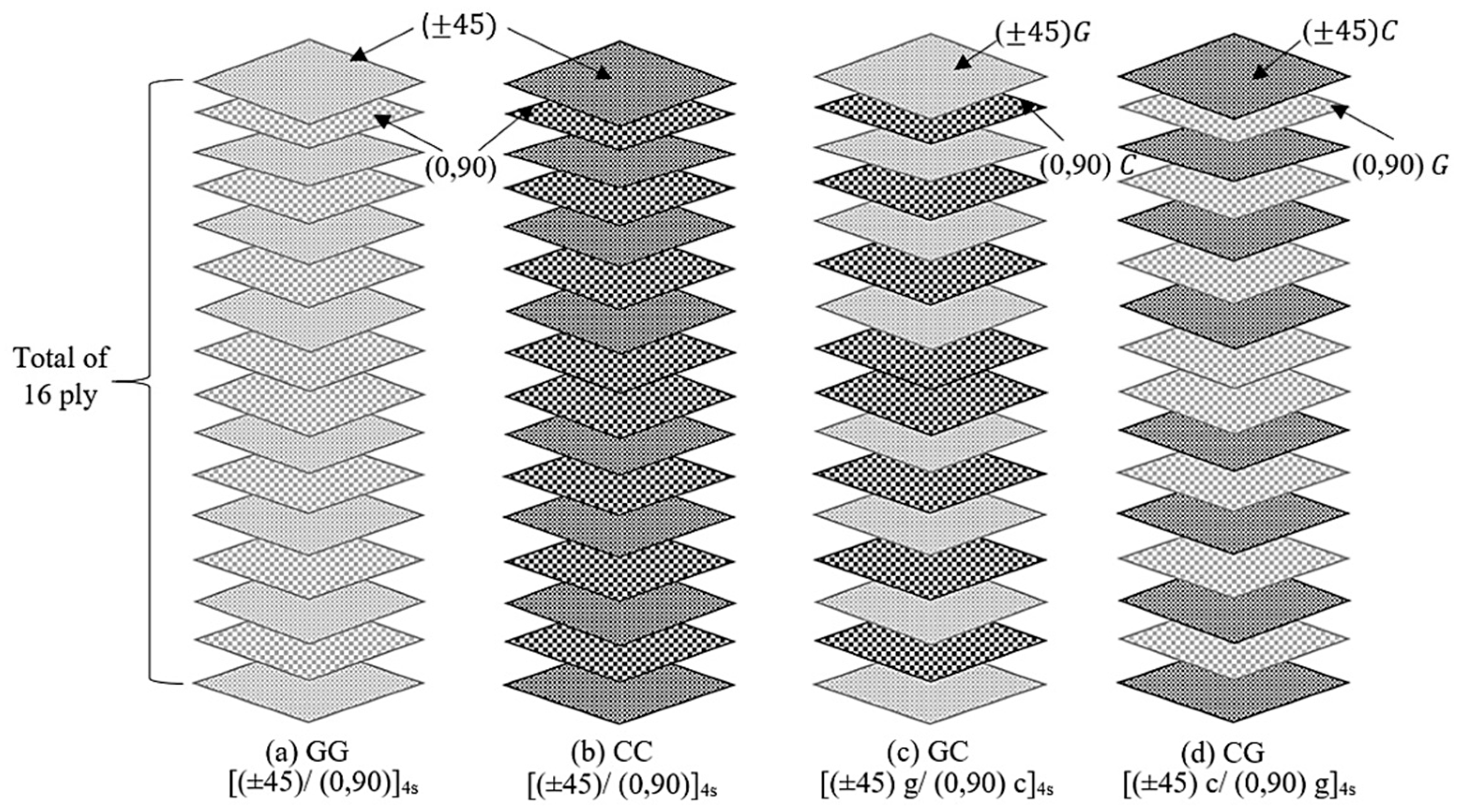
2.1. Materials

Composite laminates were manufactured by using the hand layup process at room temperature (25 °C). The epoxy resin was Epikote E51-618. M-phenylenediamine (MPD) was used as the hardener. During the fabrication of the composite laminates, plain-weave woven E-glass fiber and plain-weave woven carbon fiber fabrics were stacked layer by layer to achieve four different composite configurations. As shown in Figure 1, each laminate consisted of sixteen layers and was stacked according to a symmetric sequence: [(±45)/(0,90)]4s, where the letters G and C indicate the glass layer and carbon layer, respectively. The estimated grams per square meter (GSM) of the woven carbon fabric was approximately 272.7 g/m2, and that of the woven glass fabric was approximately 303.1 g/m2. During the layup process, each laminate was carefully impregnated with resin manually using a roller to ensure consistent wet-out and minimize air entrapment. All composite laminates were fabricated under the same environment and process conditions.
After assembly, the laminate was left to cure at ambient room temperature (25 °C) for 24 h, followed by a post-cure at 60 °C for 3 h to complete crosslinking and improve mechanical stability. According to ASTM D7137 [41], a diamond-tipped circular saw was used to cut the composite laminate into 150 mm × 100 mm × 3.2 mm plates. All test specimens were completed by abrading the edges with fine emery paper to enhance the surface quality and visually inspected for uniformity, delamination, and surface defects. Twelve specimens were prepared for the QSI and CAI tests, with each type of composite material represented by three specimens.
The densities were approximately 1515.2 kg/m3 for the glass fiber composite (GG), 1363.6 kg/m3 for the carbon fiber composite (CC), and 1439.4 kg/m3 for the hybrid laminates (GC and CG). The fiber volume fractions of GG, CC, and the hybrid, calculated using Equation (1), were 25.5%, 37.4%, and 30.8%, respectively. The approximate porosities of GG, CC, and the hybrid, calculated using Equations (2) and (3), were 1.88%, 2.99%, and 3.56%, respectively.
V f = ρ c ρ m ρ f ρ m
ρ t h e o r e t i c a l = V f ρ f + 1 V f ρ m
ρ v = ρ t h e o r e t i c a l ρ c ρ t h e o r e t i c a l
where Vf = fiber volume fraction, ρc = density of composite, ρf = effective fiber density, ρm = matrix volume fraction of the epoxy system (Epikote E51 + MPD hardener), ρtheoretical = theoretical composite density, and ρv = void volume fraction (porosity).
In engineering applications, laminated composite materials are often exposed to external impactors that can induce various types of surface damage, such as delamination, matrix cracking, and fiber breakage, which compromise coating adhesion, reduce wear resistance, and accelerate surface degradation. To ensure a more accurate prediction of surface failure, it is essential to investigate their response under various configurations and stacking sequences [40,42].

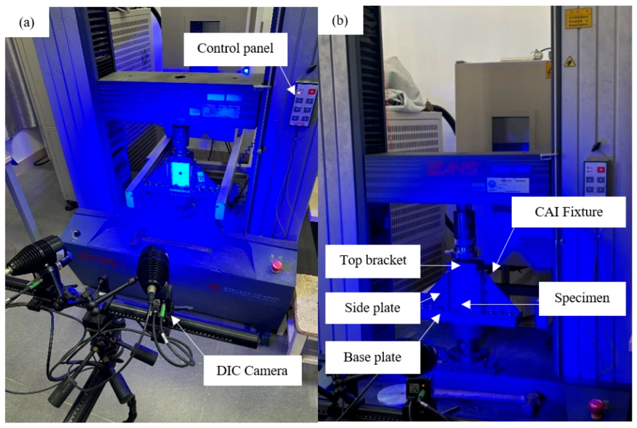
2.2. Quasi-Static Indentation Test

The method of QSI experiment, generating low-velocity indentation events in composites, would benefit researchers since quasi-static tests are considerably simpler than low-velocity impact tests [43]. Tests were conducted with the Instron 5500R universal testing machine equipped with a 50 kN load cell, suitable for moderate-force indentation on composite panels. A hemispherical indenter with a 16 mm diameter was used in the QSI test. A fixture made of stainless steel was developed and fabricated, ensuring consistency with the specimen size needed for the CAI test and securing the specimen edge during the static indentation test. The experimental setups are shown in Figure 2.
The quasi-static indentation fixture platform measures 200 mm × 150 mm in the outer rectangle and 125 mm × 75 mm in the inner rectangular hole. A 50 mm gap is maintained underneath the platform opening to enable a camera to document the bottom panel’s damage propagation during the quasi-static indentation test. Before initiating the test, the hemispherical indenter was in contact with the specimen’s faceplate. A 2 mm/min displacement load was then given to the indenter. The indenter’s displacement and the indentation force were recorded during the QSI test until the indenter entirely pierced the specimen. After the indentation test, we visually examined the laminate layer failure pattern and the depressed region of each laminate. The configuration of the indentation damage was assessed using an ultrasonic C-scan. The Ultra PAC C-scan system includes a 100 MHz A/D converter, a 5 MHz ultrasonic probe (the signal collection apparatus), motion control equipment facilitating probe movement in the X, Y, and Z axes, a storage unit, and a PC supplied with testing software. The velocity of the scanning is 0.5 mm/s [23]. The faulty layer is identified by analyzing the time difference of the acoustic wave’s return between various layers in the composite laminate. After the test, the damage to the sample is shown visually through patterns created by measuring changes in the strength of sound waves reflected from the damaged areas of the laminate surface.

2.3. Compression After Indentation Test

Following the completion of the QSI test, the CAI test was conducted using the MTS E45 microcomputer-controlled Instron 5982 universal testing machine, which has a maximum load capacity of 300 kN. The indentation process resulted in localized defects, including delamination, fiber breakage, and matrix cracking, varying with material properties and the applied load. The CAI test can be used to evaluate the indentation defects on the structural integrity and compressive load tolerance and provide valuable information about the correlation between induced damage and the material’s ability to resist compressive failure. Testing all twelve specimens allowed for a thorough assessment of the materials’ damage tolerance and the extent of mechanical performance degradation caused by indentation. The DIC system, manufactured by GOM in Germany, includes a control computer system, a CCD-detecting lens, and calibration tools. The system exhibits a calibration deviation of 0.021 pixels, which is below the minimum acceptable value of 0.050 pixels. Additionally, the scale variable is 0.001 mm, which is within the threshold of 0.014 mm [23]. To prevent spatial buckling, a fixture is equipped with four laterals, each of which is fixed on two sides at the top and lower layers. A displacement-controlled loading mode was applied with a compressive loading rate of 0.5 mm/min to achieve quasi-static loading. The laminates were fastened using the CAI fixture throughout the experiment process. The fixture design shown in Figure 3b conforms to the ASTM D7137 standard. When the load decreased by 20% while the compression process was ongoing, the compression loading process was immediately stopped. The DIC system recorded out-of-plane displacement at a frequency of 1 Hz during the compressive loading process, providing full-field deformation measurements by tracking the speckle pattern on the laminate surface.

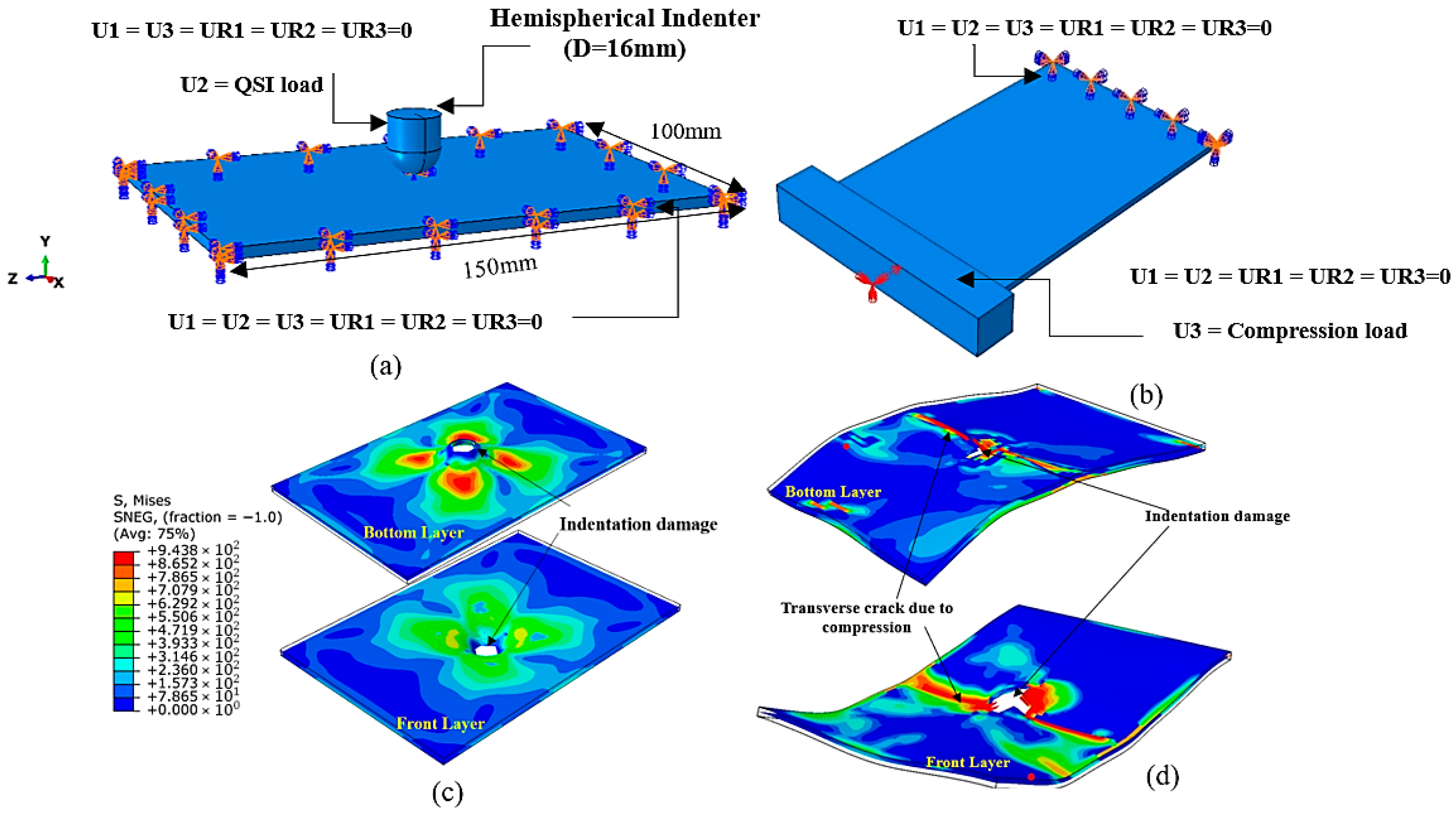
2.4. Numerical Modeling

Numerical analysis is a reasonably accurate, cost-effective, and time-efficient method for representing and evaluating the mechanical performance of hybrid composite laminates that are being experimentally studied. Two analysis steps were included in the finite element model (FEM) using Abaqus/Explicit software. The first step was to simulate the indentation test of the laminate. The second step was to simulate the post-compression test. In the FE model, both the compression head and indenter were modeled as rigid elements (element type R3D4), as shown in Figure 4. Each ply of the laminate with a thickness of 0.2 mm was modeled using the Composite Layup Manager tool, ensuring accurate representation of the stacking sequence and fiber orientations. The dimensions of the laminate are 100 mm × 150 mm × 3.2 mm, as shown in Figure 4a. Each ply in the laminate was modeled with one element through the thickness.
The boundary conditions in the two steps of finite element analysis (FEA) were slightly different. In the first step (QSI test), all laminate edges were clamped by setting all translational and rotational degrees of freedom (DOFs) to zero, namely, U1 = U2 = U3 = UR1 = UR2 = UR3 = 0. Except for the DOF (U2) in the loading direction, the other five DOFs of the indenter were set to zero (U1 = U3 = UR1 = UR2 = UR3 = 0), as shown in Figure 4a. The same displacement (U2) load as in the QSI test was applied to the indenter.
In the second step (CAI test), one edge was fixed (U1 = U2 = U3 = UR1 = UR2 = UR3 = 0). Except for the DOF (U3), the other five DOFs on the loading edge were zero (U1 = U2 = UR1 = UR2 = UR3 = 0), as shown in Figure 4b. The same displacement (U3) load as in the CAI test was applied on the loading edge. This detailed modelling approach ensures the accurate simulation of both the indentation and the subsequent behavior of the composite laminate under compressive loading conditions. For progressive damage analysis, the Hashin damage criteria were applied to simulate the damage mechanisms of fibers and matrix. The material parameters obtained from preliminary mechanical tests for the glass/carbon fiber laminate are presented in Table 1, Table 2 and Table 3, including the longitudinal modulus E1; the transverse modulus E2 and E3; Poisson’s ratios in three directions v12, v13, v23; shear modulus in three directions, G12, G13 and G23; as well as tensile and compressive strengths in fiber, transverse, and normal directions, along with transverse shear strengths XT, XC, YT, YC, ZT, S12, S13 and S23 [44]. These material properties are used in the FE simulations.

3. Results and Discussion

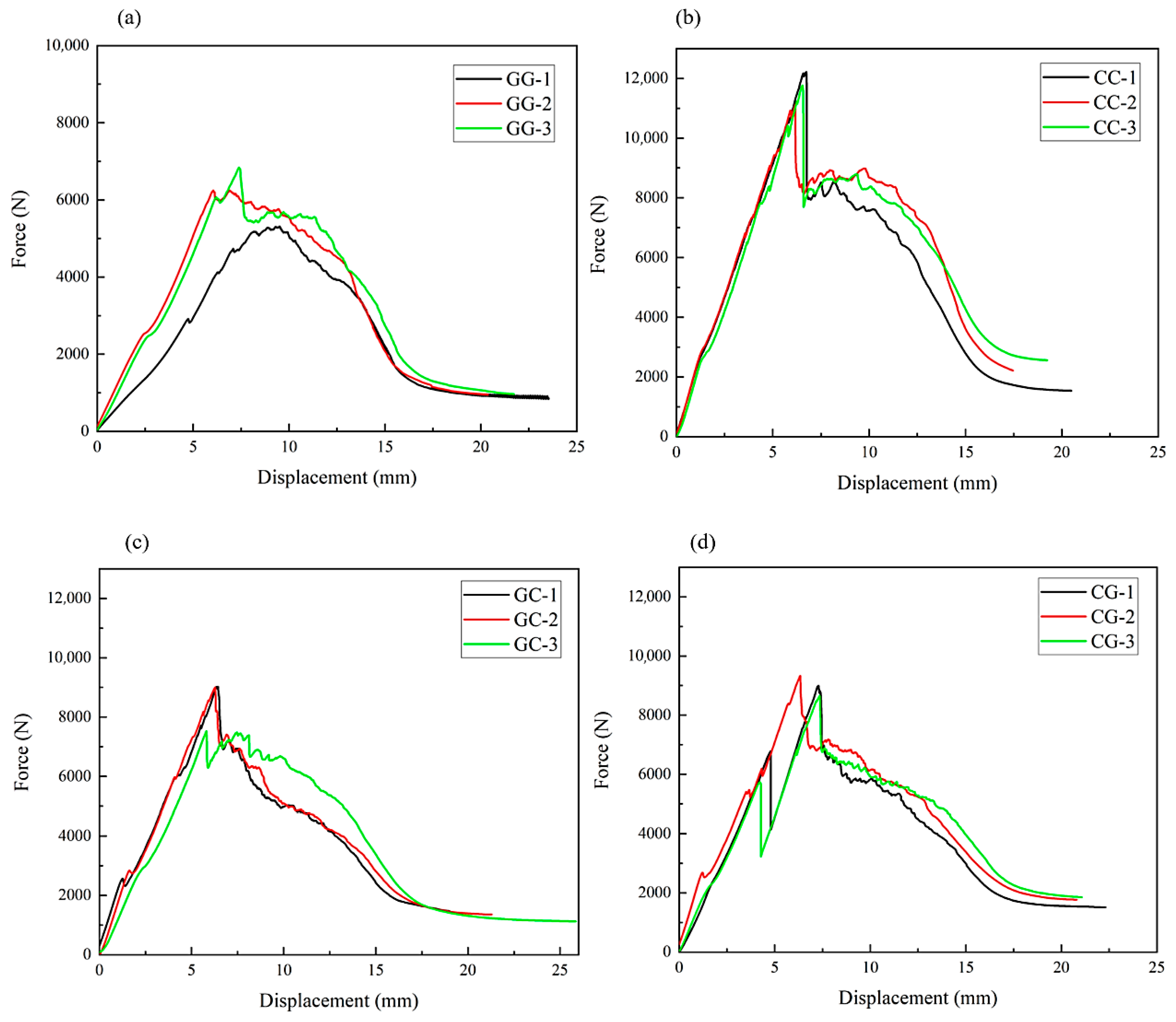
3.1. QSI of Hybrid and Non-Hybrid Woven Composite Laminates

The QSI test was used to examine the response of woven hybrid composite laminates under a localized force. For each material setup, three samples were repeatedly tested under the same loading rates and conditions. The experiment continued until the specimens were completely perforated. Matrix cracking was observed in the lower layer of the specimens during the initial age. Local cracking occurred in resin-rich zones between fiber bundles when the load reached the peak force. After that, the load dropped rapidly with an increase in displacement load. Fiber fracture, particularly under the indenter, was observed. At the interface between the fibers and matrix, load transfer is interrupted, resulting in a decrease in the strength and stiffness of the specimens. As the indentation progressed, the indenter perforated the front layer, resulting in permanent deformation and non-recoverable denting beneath the indenter. The damage process of each sample enabled the determination of the maximum force prior to failure for each specimen, as well as the associated displacement, the damage area, and the energy absorbed by the material during total perforation. Figure 5 illustrates the load-displacement curves for all twelve specimens. Due to the ductile behavior, GG specimens exhibit a more gradual and distributed failure with less elastic energy conserved, resulting in fiber deformation rather than catastrophic failure. Compared to GG-2 and GG-3, GG-1 demonstrates a significantly lower slack in the initial loading stage, which results in a reduced maximal force. The slight discrepancy may be caused by material heterogeneity and localized imperfections, such as resin-rich zones, voids, and fiber misalignments. The load-displacement curve of CC specimens shows an increased peak load. Although elongation fracture of carbon fibers affects only half of the glass fibers, carbon woven composites have excellent strength-to-weight ratios and stiffness [45]. The glass factsheets hybrid configuration (GC) exhibits greater gradual deformation, whereas the carbon factsheets hybrid configuration (CG) exhibits slightly steeper initial slope. Due to the balanced contributions, the difference in the peak load of the two hybrids is small, only 477.5 N. Perhaps due to a small error in the hand-up manufacturing process, such as misalignment, the load-displacement curve of GC-3 is slightly different from those of CG-1 and CG-2. Overall, the repeat performance is good and acceptable.
Table 4 summarizes the highest load and movement for the indenter’s penetration into the samples for each case, along with the key values and their relative standard deviations. Although the results of both hybrid versions are comparable, the CG samples show a slightly greater force peak and larger displacements than the GC samples.
Figure 6 shows the indentation-damaged areas in the top and bottom face layers of the specimens after QSI. The specimens exhibit elastic behavior and no significant damage during the initial linear behavior of the load vs. displacement curve. However, as the indentation load increases, the number and size of delaminations on the bottom surface increase, causing visible matrix cracking, fiber failure, and a major loss of structural integrity due to the tension. Internal damage can be observed and correlated with the force-displacement response. The CC specimens exhibit catastrophic failure with a clean and sharp fracture on the bottom layer, whereas GG-1 and GG-2 exhibit expansive delamination with ruptured fiber patterns. CG specimens have substantial bottom layer dent, whereas GC-1 and GC-2 exhibit more internal fiber fracture and perforation.
During the experiment, energy is absorbed by the deformation of the laminate, matrix cracking, and the fracturing of the fibers during the indentation process. The specimen absorbs more energy as the region of indentation damage expands. The local tension generated by the indenter causes the damage to expand throughout the laminate. Due to its superior energy absorption capacity compared to glass fiber, the fiber fractures in CC specimens and both hybrid specimens are more pronounced than those in GG specimens under indentation force.
Figure 7 displays the damage patterns and locations identified by the C-scan technology on the samples after finishing the QSI test. A portion of the vertically displayed A-scan waveform is represented by the C-scan color mode. In order to identify the internal damage, the deeper the color, the smaller the wave’s fraction, indicating greater degrees of laminate damage, as compared to the damage contour outcomes. The damage zone of GG is more localized, with a mean damage area of 275.7 mm2. The biggest damage area was seen in the CC specimen. The damage extended asymmetrically in the CC-2 specimen and beyond the major depression zone. This was most likely caused by poor interlaminar bonding or damage from prior handling of the specimen. Although the damage resistance of the two hybrid samples is comparable, the CG specimens exhibit a slightly greater discrepancy of 19.7 mm2 in damaged regions compared to the GC specimens. This is primarily due to carbon facesheets dissipating a considerable amount of energy via fiber matrix debonding and delamination growth [46].
The absorbed energy can be employed as a damage index, namely, a higher absorbed energy indicates greater damage. The primary energy absorption mechanisms are fiber shear, fiber fracture, and delamination [47]. Table 5 lists the average specific absorption energy (SAE), which can be determined from each sample’s energy and the exact weight of the average area of damage and energy needed for the indenter to penetrate in each situation. The analysis of indentation damage across several specimens indicates notable disparities in damage resistance and energy absorption. The average penetration energy of the indenter for CC specimens is 37.9 J, the maximum one among the four types of specimens, whereas the SAE is 0.5790 J/g. The energy required for indenter penetration in GG specimens is 24.1 J, and the minimum among the four types of specimens has an SAE value of 0.3314 J/g. GC showed balanced energy and damaged area compared to GG due to the glass facesheets, which resist failure. The carbon facesheets of the CG specimen enable initial strength and energy absorption, and thus absorb more energy due to matrix cracking and fiber breakage as the region of indentation damage expands. The energy penetration of the GC specimen is 15.97% lower than that of the CG specimen. This disparity is due to the fact that central glass woven laminates are less stiff than carbon fiber, resulting in lower indentation durability and a reduced energy absorption capacity. However, the damage area of CG is 6.35% greater than that of GC, implying more surface damage in the carbon facesheet. The elongation characteristic of GC is indicative of its greater suitability for lightweight structures, as it exhibits a 5.31% lower peak load than CG specimens. This elongation characteristic is more effective in resisting indentation forces.
The stacking sequence of hybrid composites greatly influences damage initiation and propagation during QSI owing to differing mechanical characteristics of the components. When subjected to a high indentation load, carbon woven tends to have a larger damage area and distribute the stress over a wider range, which leads to absorbing more energy. In contrast, glass-woven laminate shows more localized damage with less severe delamination and cracking. Hence, hybrid woven composite laminates, such as glass/carbon and carbon/glass hybrid configurations, exhibit distinct behaviors compared to pure carbon and pure glass woven composite laminates, balancing stiffness and energy absorption.

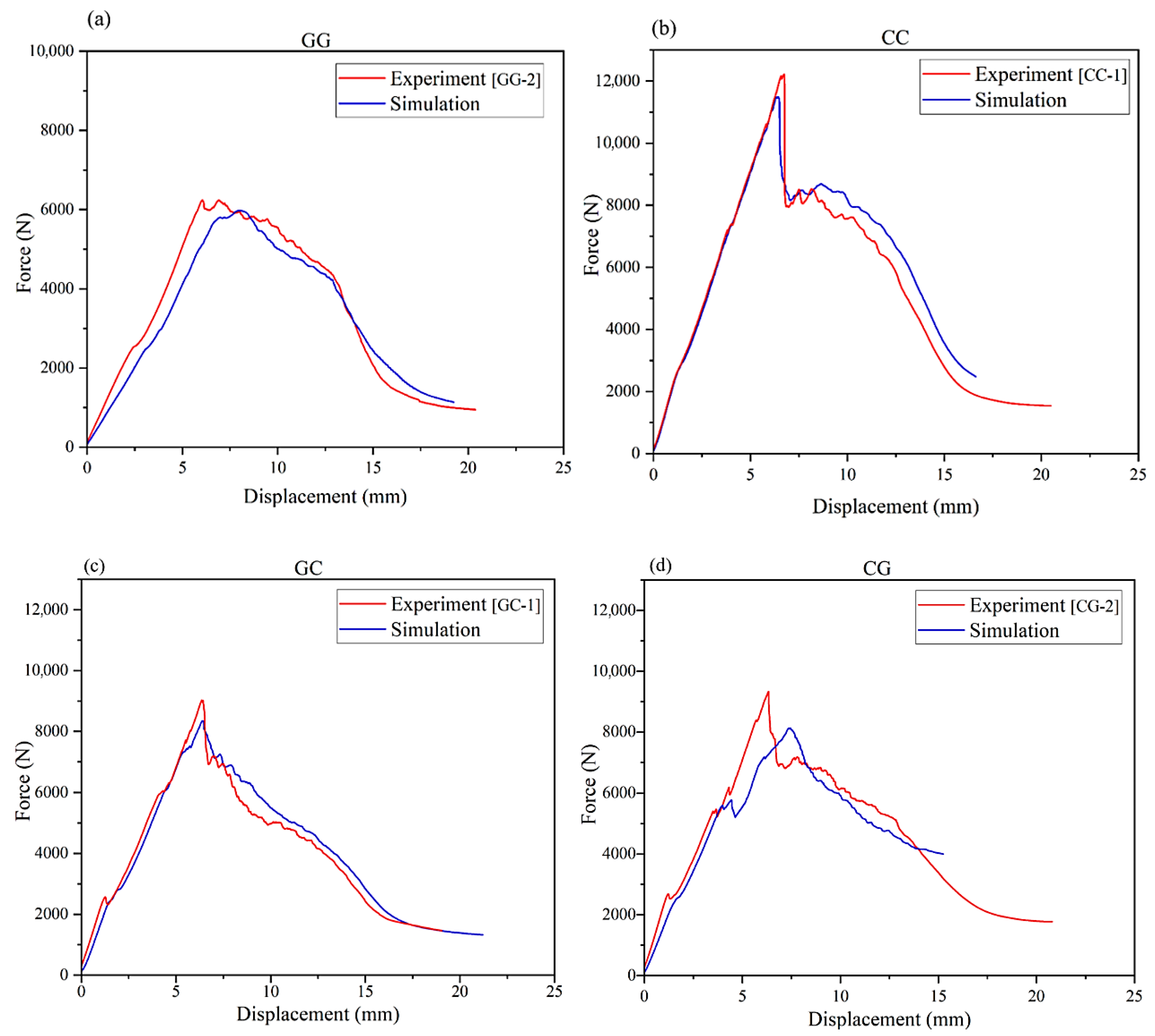
3.2. Numerical Analysis of the QSI Test

A series of FE simulations were carried out to investigate the behavior of the four types of hybrid and non-hybrid woven composite laminates under QSI. Simulations can show the details of the indenter penetrating the laminate layers, damage initiation and propagation, and penetration resistance. The indentation responses are closely correlated with the experimental results, and thus, the established FE models are validated. Figure 8 displays the FE simulation results using Abaqus for four kinds of woven composite laminates with stacking sequences of [(±45)/(0,90)]4s, [(±45)/(0,90)]4s, [(±45)g/(0,90)c]4s, and [(±45)c/(0,90)g]4s, including distributions of von Mises stress, fracture toughness (HSNFCCRT), and matrix compression damage (DAMAGEMC) in two facesheets.
The von Mises stress distribution can show the severe stress locations, facilitating the identification of potential failure areas. HSNFCCRT provides insights into the material fracture resistance, crucial for predicting failure under severe stress. The DAMAGEMC illustrates the degree of damage accumulation in the composite, visually depicting each laminate’s response to indentation. Analyzing these data reveals that the simulations are comparable to the experimental ones [48]. Hence, the established FE models are reliable and can be used to study the QSI behavior of hybrid woven composite laminates with dimensions and material properties.
Figure 9 shows the comparisons of simulated and test load-displacement curves for QSI tests. The experimental curve represents the values from one specimen and not the mean values of the three specimens for each case. It is seen that the maximum error of peak load is small and approximately 3.29% for GG, 5.81% for CC, 3.53% for GC, and 6.4% for CG, respectively, since the closest load-displacement curve to the simulated one is used in Figure 9. The differences between simulated and test load-displacement curves are caused by experimental and modeling errors. Experimental results may be influenced by external factors such as humidity, temperature, manufacturing imperfections, and operator-induced variability, absent in simulations. Numerical simulations may not capture the exact complexities of hybrid laminates, such as fiber-matrix interactions and micro-level defects, which deviate from the real experiments. Overall, the experimental and numerical results for the four laminates have a good correlation.

3.3. CAI Behavior of Hybrid and Non-Hybrid Woven Composite Laminates

The residual compressive strength (RCS) evaluated by the CAI test on QSI-damaged specimens is a key issue in the application of hybrid composite materials. RCS is an essential measure of structural performance, which may be significantly reduced or diminished considerably depending on the severity of indentation damage, laminate layup, and material properties. The extent of indentation damage directly affects the specimens’ compression stiffness and compression strength [49]. The compression load exhibits a rapid decline at the specimen’s failure due to the supplementary damage at the interface between the laminate and the indentation damage during the CAI test. The load-displacement curve illustrates a reduced peak load and abrupt failure subsequent to the attainment of the critical load, shown in Figure 10. In the initial stage of compression, all curves exhibit a linear response. Subsequently, the load-displacement curve departs from linearity as a result of the local warping of the indentation damage area. Transverse fractures in the laminates penetrate the indentation damage area when the maximum load is achieved, resulting in the specimen’s failure and a sudden decrease in load. A premature damage mechanism under the compression and the increase of delamination between the carbon and woven glass layers might cause the GC-3 to exhibit an uneven fluctuation. The horizontal plateau in the load-displacement curve of CG-1, indicating steady stress propagation, suggested an early internal instability that temporarily absorbed the load without increasing resistance.
Table 6 presents the mean failure loads, bearing efficiency, and residual compressive strength (RCS) values of the hybrid and non-hybrid woven composite laminates under CAI. It is seen that CC laminates exhibit the greatest RCS, the lowest failure strain, and consequently the highest bearing efficiency among the four composite laminates. The opposite applies to the GG laminates. The hybrid woven composite structures exhibit a degree of ductility due to the combination of specific amounts of ductile glass fiber and brittle carbon fiber in their composition. GC achieves an RCS of 91.04 MPa, 4.45% higher than CG, 31.68% higher than GG, and 19.83% lower than CC, while the RCS of CG is 26.06% higher than GG and 23.26% lower than CC specimens. Besides, the bearing efficacy of GC is 4.31% higher than that of CG. Hence, the GC specimens exhibit higher RCS than CG, facilitated by efficient load transfer due to the structural strength of the carbon layers. The outer layer of glass fiber balances load-bearing capability with energy absorption by surface damage. These findings demonstrate that hybrid laminates (GC and CG) exhibit distinct failure behavior under compression after indentation, influenced by their stacking sequence in terms of energy dissipation and structural integrity after indentation. GC outperformed CG in the hybridization process, where each material exhibited characteristics influenced by its respective proportion in the mixing ratio. As a result, an increase in carbon fiber content in the middle would certainly enhance compressive strength and damage resistance, thereby improving specific strength and stiffness.
Figure 11 shows the Digital Image Correlation (DIC) damage patterns in the top surface of the indentation-damaged hybrid composites in the CAI test under different loads. Capturing damage patterns can provide insight into the post-indentation behavior and residual damage in the laminates, including delamination propagation, fiber fractures, and localized stress concentrations. The damage evolution can significantly influence the composite’s residual compressive strength.
The DIC damage patterns in the top surface of the glass woven composite laminate (GG) indicate that compression deformation (buckled in) occurs in the top surface under compressive loads of 5 kN and 11.6 kN, and that damage is visible at the load of 18.5 kN. After the peak force, the top surface becomes a weak region due to stress concentrations caused by QSI damage, resulting in the propagation of transverse cracks that extend through the composite layers. The deformation and damage propagation in the top surface of CC, CG, and GC woven composite laminates with the increase of load can also be seen from their DIC damage patterns. The deformation of GC and GC hybrid laminates is similar to that of GG when the load is small. However, the deformation of CC laminate is opposite to that of GG; tensile deformation (buckled out) occurs in the top surface. In the case of a large load, the deformation of the CG laminate is tensile (buckled out) on the upper part of the indentation damage and compressive (buckled in) on the lower part of the indentation damage, quite different from that of GC.
The visible failure for the CC, GC, and CG composite laminates occurs at the load of 32.7 kN, 27.3 kN, and 24.1 kN. For the two kinds of hybrid composite laminates, the GC hybrid composite laminate has a slightly higher residual load-bearing capacity. In other words, placing glass fiber on the two faces of the laminate may be beneficial for the residual load-bearing capacity.
Figure 12 shows the total perforation in the front and bottom layers of two specimens in each group evaluated during CAI at 90% of the failure load. The laminate has deteriorated due to early indentation damage from the quasi-static indentation test. As the stress continues to grow, the matrix of the front layer and bottom layer fractures, ultimately leading to fiber dislocation and a loss of load-bearing capability in the specimen. Specimens exhibit matrix cracking on the bottom face, delamination inside the indentation damage zone, matrix cracking, and fiber pullout within the indentation damage area. At a proportion of 90% failure load, both CC and GC specimens exhibit more assertive cracking than the GG and CG specimens. The analysis of experimental results reveals an interaction between delamination and matrix fracture in hybrid woven composite laminates. The results of carbon (CC) composite reveal that the brittle nature causes localized damage and rapid fracture propagation under high stress, but the high stiffness and strength, combined with low strain-to-failure, also provide a higher load-bearing capacity and resistance to deformation. Conversely, due to the ductile properties, glass fibers significantly improve the capacity to deform prior to fracture, enabling prospective applications that require flexibility.

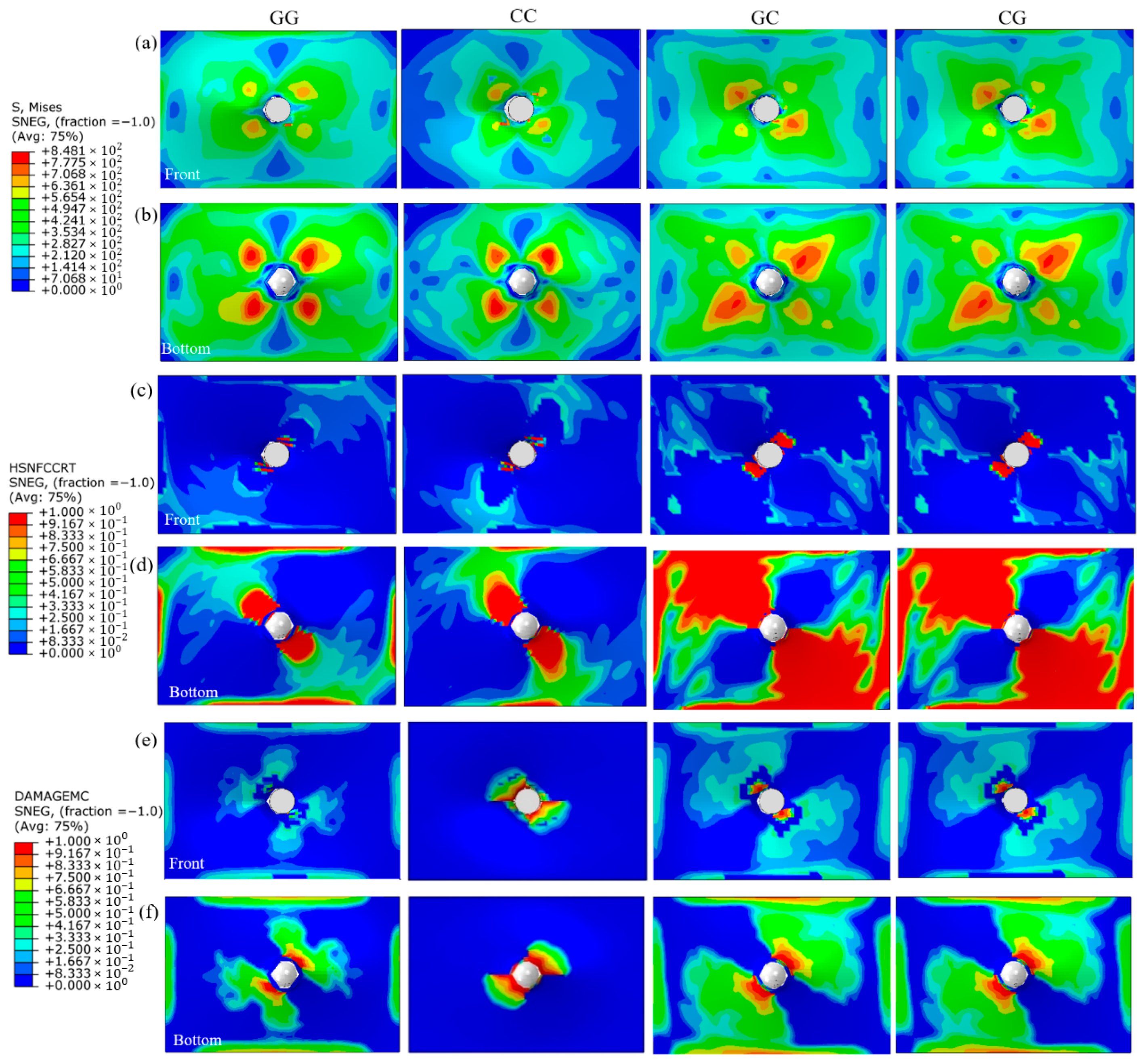
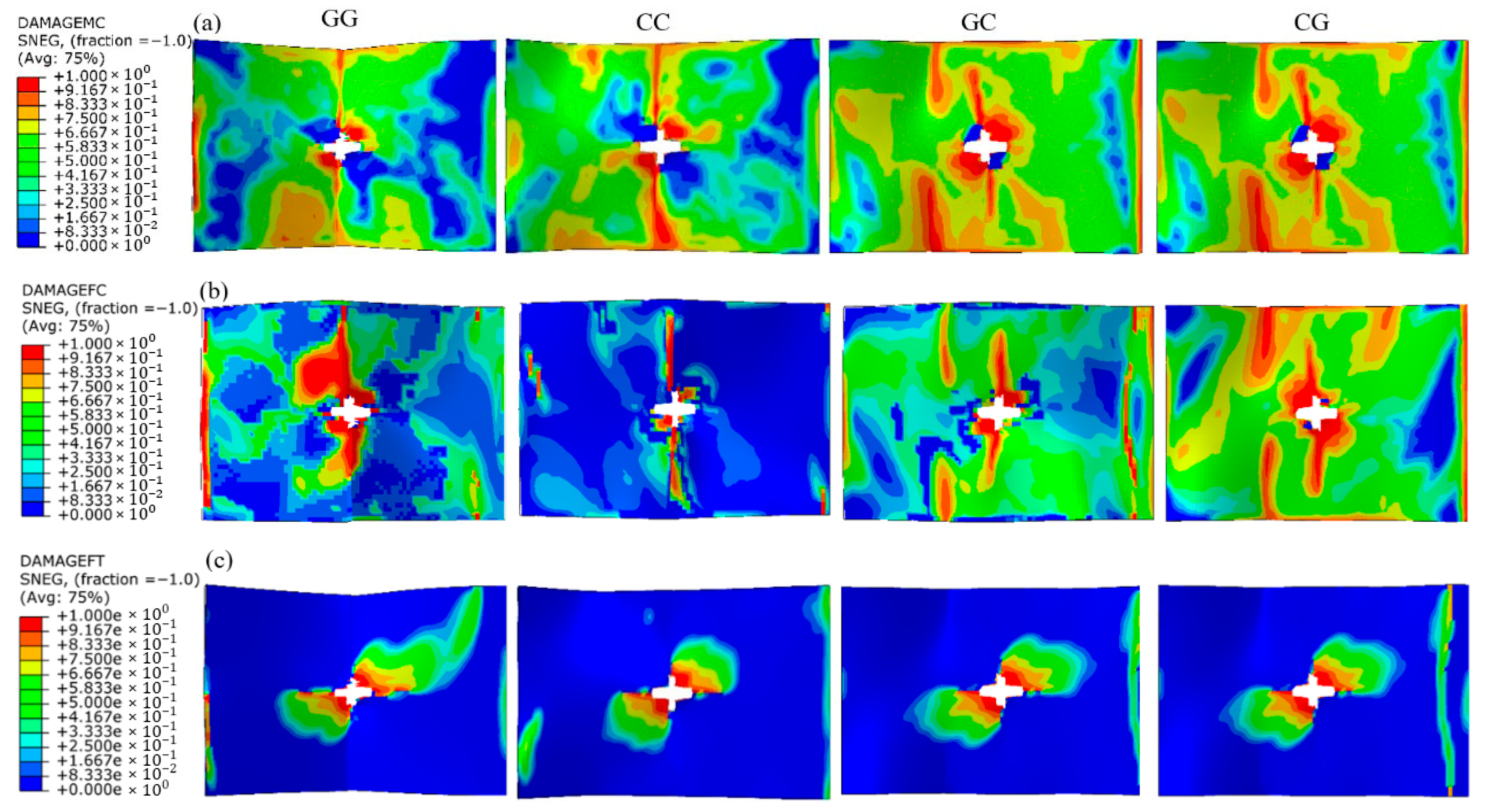
3.4. Numerical Analysis of the CAI Test

The CAI finite element models were established based on the models utilized in prior indentation research. The indentation damage patterns (failed laminate portions) are retained in the CAI model and simulations. The boundary conditions are different from the QSI model, as mentioned previously. FE simulations were performed using Abaqus/explicit finite element software.
Figure 13 shows the CAI simulated results for the four woven composite laminates and the distribution of damage patterns. DAMAGEMC (matrix compression damage) analysis reveals that the onset of delamination is widespread during loading, with matrix cracks initiating in the red regions at the peak load. DAMAGEFC (fiber compression damage) shows high local stiffness loss, while DAMAGEFT (fiber tension damage) indicates complete fiber failure and damage accumulation. Simulations illustrate how damage initiates and propagates in the indentation-damaged laminates under compressive force. Examining the distribution and intensity of these damage indicators can identify weak zones, the interaction between fiber and matrix damage, and the effectiveness of hybrid topologies in preventing failure.
Figure 14 displays comparisons of the simulations and the experimental data. It should be mentioned that the test load-displacement curve is from a single specimen and not the average of three specimens. It can be intuitively observed that the maximum error of peak load is small and approximately 4.35% for GG, 2.56% for GC, and 3.85% for CG. However, the difference of simulated and test peak load of CC is high and reaches 27.55%. The possible reasons are that the numerical model may not perfectly catch the real damage mechanisms of the CC-1 specimen, and the test peak load of CC-1 is the highest among the three specimens, seen from Figure 10b. The hand-up manufacturing process may cause inherent imperfections, such as voids, fiber misalignment, or resin-rich areas, difficult to replicate in simulations.

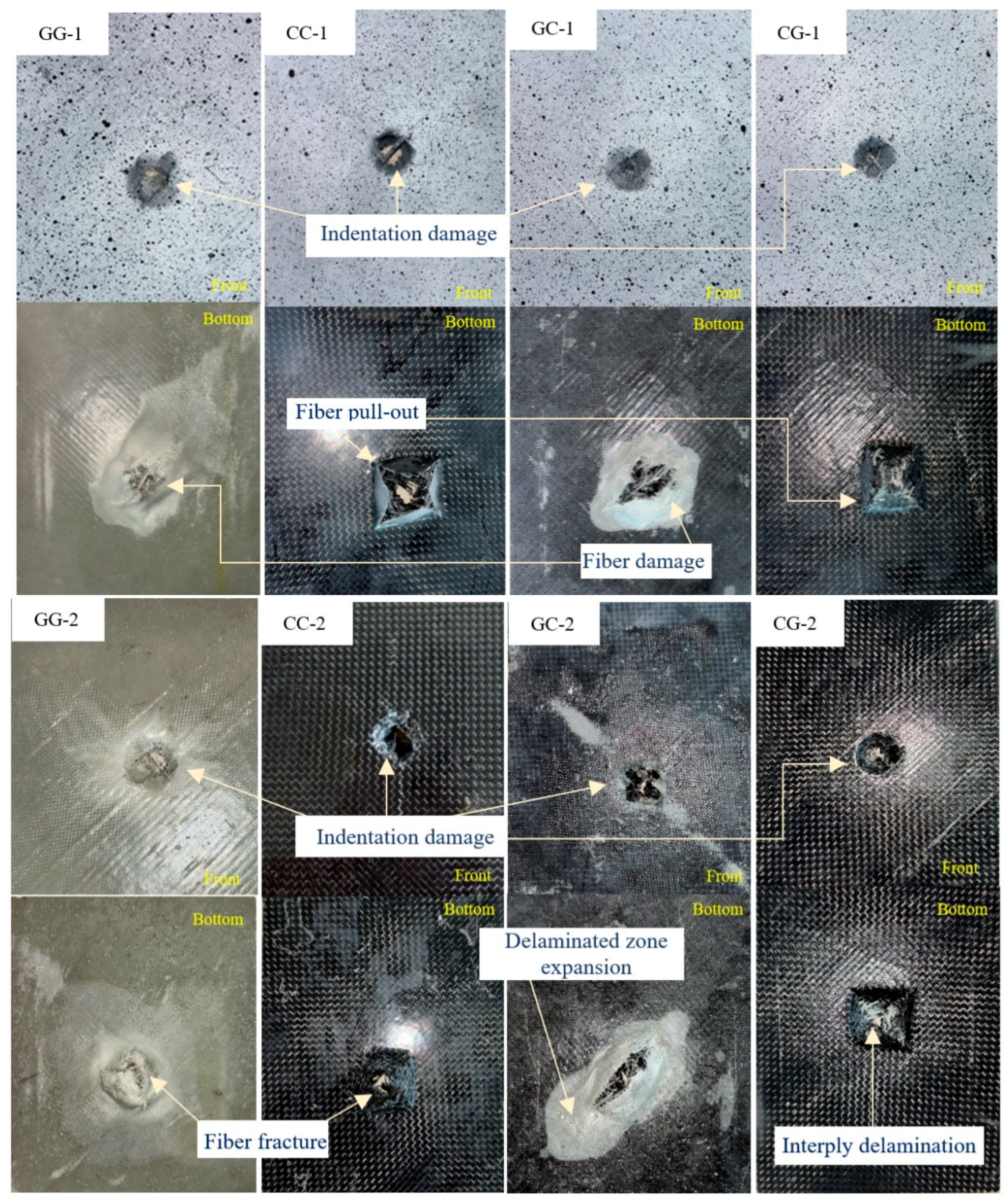
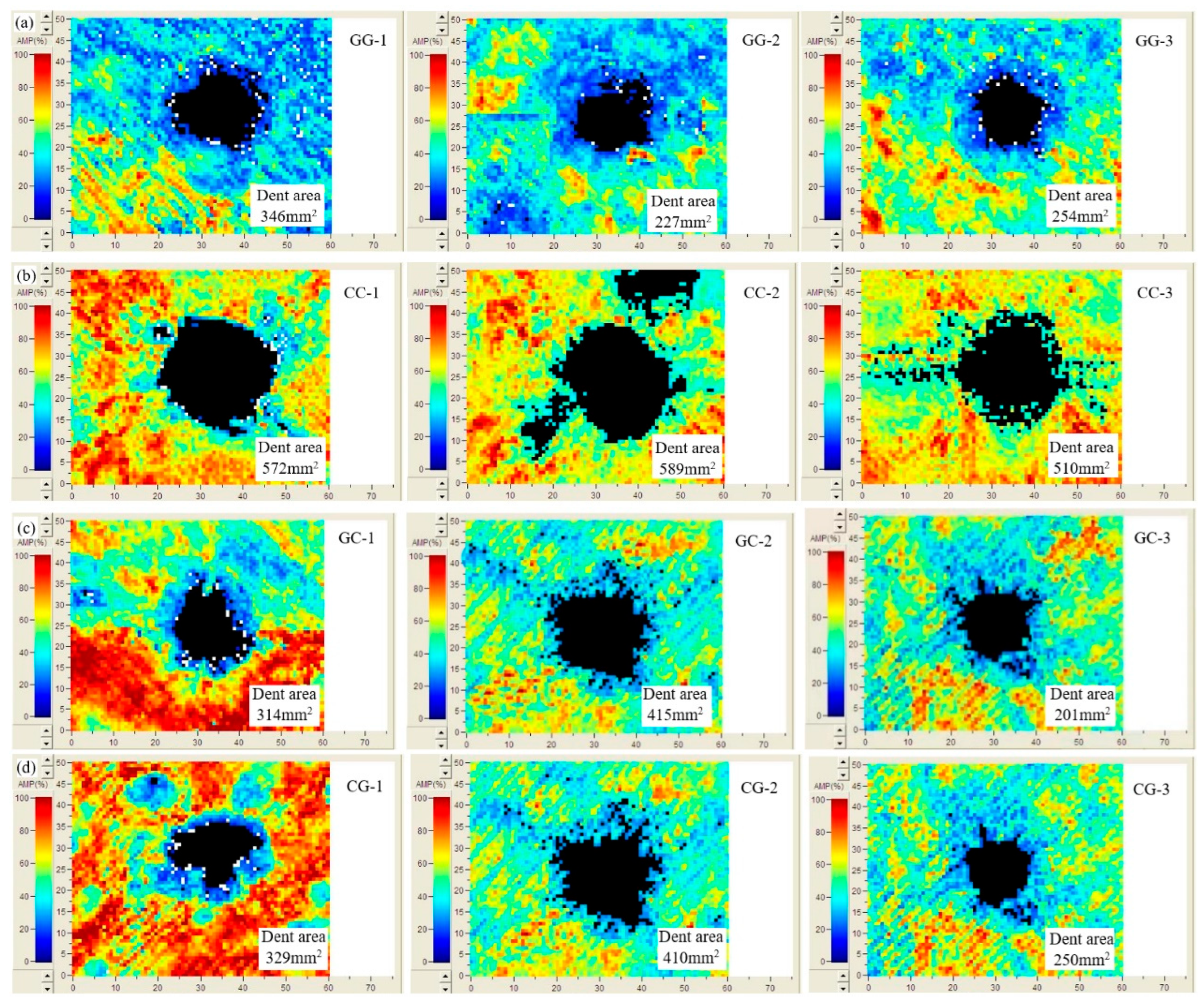
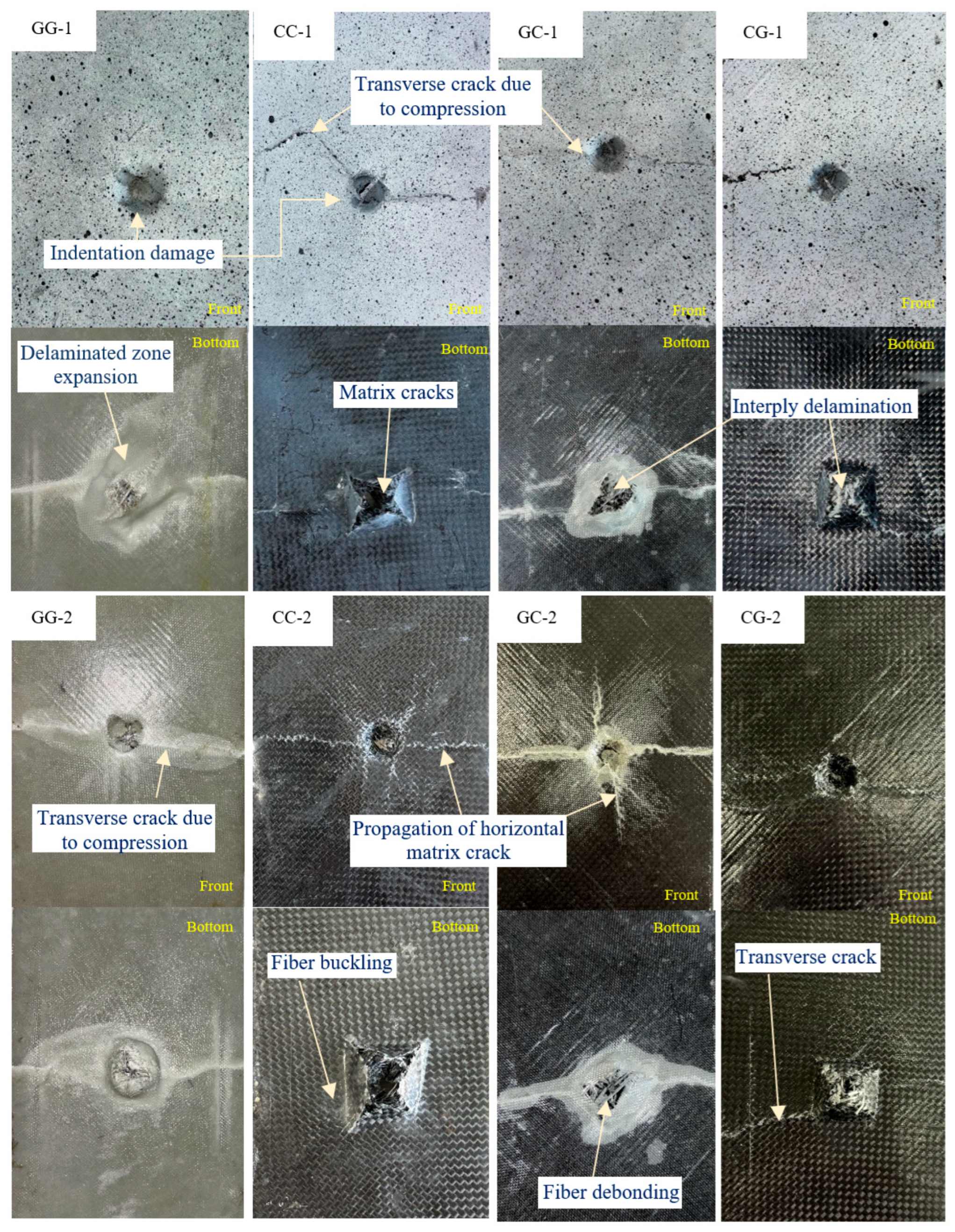
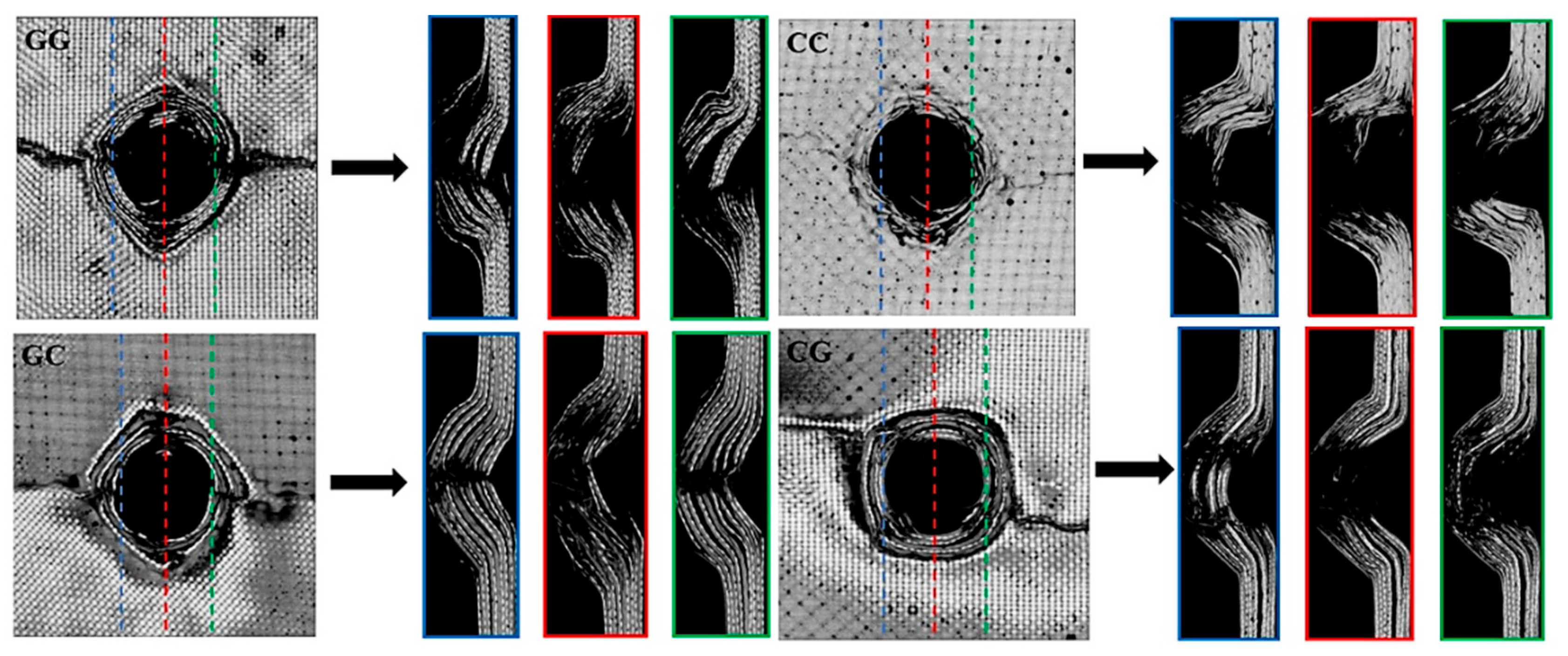
3.5. QSI and CAI Damage Mechanism

The evolution of the damage mode in the laminates during the QSI test can be categorized into five distinct stages, ranging from the initial contact with the indenter to the penetration of the laminate front layer completely. The fabric layers compress initially before the indentation load reaches the maximum load, and micro matrix fractures caused by stress concentration produce cracks to emerge at the front face. During the second stage, once the indentation force attains the maximum load, fiber fractures occur due to compression, leading to the expansion of cracks in the front layer of the laminate. The indentation force causes the fibers interacting with the indenter to pull out and fracture, which reduces the stiffness of the specimen’s top layer. Indentation damage causes separation to occur in the affected area. During the third stage, the bottom face layer is penetrated by the indenter, and the discontinuous pressing action of the indenter exhibits failure modes such as matrix splitting, fiber debonding, and fiber pull-out. The cross-shaped crack resulting from the fiber fracture persists in its extension toward the tip of the indenter. The matrix crack propagates along the indentation direction of the front layer, while the indentation load exhibits oscillatory behavior. In the fourth stage, there is a reduction in strength and cohesive energy at the interfaces of the laminate sheets beyond the delaminated area. Within the indentation damage zone, matrix and fiber cracking are observed. During the last (fifth) stage, the indentation causes the bottom face sheet to bend, which contrasts with the front layer bending in the first stage. Cracks in the matrix manifest around the indentation zone, with significant fractures propagating along the fiber orientation towards the periphery of the indentation region.
Figure 15 shows the CT scan images, where the red color represents the cross-section at the center of the specimen, with the indentation damage caused by static pressure, while the blue and green colors represent the cross-section at the edge of the damaged indentation area.
Observing the cross-sectional image reveals that the damage pits in all four types of laminates are nearly circular with a diameter of 16 mm, consistent with the size of the indenter. For CC specimens, the fibers at the edge of the indentation area are completely fractured due to the highest failure load, almost identical to the damage at the center. However, in the other three types of specimens, a small amount of glass fiber remains connected at the edges of the indentation, indicating that glass fibers have larger deformability than carbon fibers. CT images further clarify that during the compression process after indentation, transverse crack propagation occurs on both sides of the indentation area perpendicular to the compression direction.
During the compression after indentation test, specimens experience a reduction in their load-bearing capacity, and matrix cracks develop in the face sheets beneath the indentation zone due to increased compression deformation near the supporting fixture. The matrix experiences shear failure, resulting in the fracture of the fibers. Analyzing CAI responses of two kinds of hybrid woven composite laminates reveals that GC tends to preserve more residual strength, providing better energy absorption and damage resistance during indentation, reducing stress concentrations, and limiting crack propagation. Conversely, a front layer with carbon fibers may allow cracks to propagate more easily through the brittle matrix, significantly reducing the residual strength.

4. Conclusions

The QSI and CAI behavior and failure mechanisms of hybrid woven composite laminates were experimentally and numerically investigated in this paper. Although the carbon/glass (CG) hybrid composite laminate absorbed more impact energy on average (31.3 J) than glass/carbon (GC) hybrid composite laminate (26.3 J), carbon fibers on the outer layers exhibited a higher average damage area (329.7 mm2) and greater displacement (6.99 mm) under QSI, which indicates the CG configuration was more prone to brittle surface failure and crack propagation due to the carbon outer layers. In contrast, the GC hybrid composite laminate, with glass fibers at the surface, exhibited a reduced damage area (310.0 mm2) and lower indentation displacement (6.14 mm). During the CAI, GC laminates exhibited more stable post-indentation deformation and efficient strength-to-weight performance, with slightly higher bearing efficiency (421.25 N/g) than CG laminates (403.85 N/g). CG laminates exhibited deeper intralaminar cracks that were initiated from the outer layers.
The simulated and test QSI peak force differences for the four specimens are 3.29%, 5.81%, 3.53%, and 6.4%, and test CAI peak force differences for the four specimens are 4.35%, 27.55%, 2.56%, and 3.85%, respectively, indicating a significant correlation between test and simulated results. These results show that selecting glass as the outer layers and carbon on the inner layers in symmetrically stacked hybrid composites can improve surface toughness and resistance to indentation-induced damage, benefiting from maintaining surface integrity, which is critical in applications requiring reliable post-impact coating adhesion. The results support the advancement of hybrid woven composite laminates and the development of durable, high-performance materials for structural applications.

Author Contributions

Conceptualization, D.C.; Methodology, H.U.H. and D.C.; Software, H.U.H. and L.I.; Validation, H.U.H., P.L.M. and L.I.; Formal analysis, D.C.; Investigation, H.U.H.; Resources, D.C.; Data curation, H.U.H.; Writing—original draft preparation, H.U.H.; Writing—review and editing, D.C. and X.W.; Visualization, H.U.H. and P.L.M.; Supervision, D.C.; Project administration, D.C. and X.W.; Funding acquisition, D.C. All authors have read and agreed to the published version of the manuscript.

Funding

This work was partially supported by the National Natural Science Foundation of China (Grant No. 52005256) and the Priority Academic Program Development of Jiangsu Higher Education Institutions.

Institutional Review Board Statement

Not applicable.

Informed Consent Statement

Not applicable.

Data Availability Statement

Data is contained within the article.

Conflicts of Interest

The authors declare no conflicts of interest.

References

  1. Ravishankar, B.; Nayak, S.K.; Kader, M.A. Hybrid composites for automotive applications—A review. J. Reinf. Plast. Compos. 2019, 38, 835–845. [Google Scholar] [CrossRef]
  2. Zhang, K.; Shi, D.; Wang, W.; Wang, Q. Mechanical characterization of hybrid lattice-to-steel joint with pyramidal CFRP truss for marine application. Compos. Struct. 2017, 160, 1198–1204. [Google Scholar] [CrossRef]
  3. Thibault, P.A.; Hernandez, A.R.; Mills, H. Shear driven deformation and damage mechanisms in High-performance carbon Fibre-reinforced thermoplastic and toughened thermoset composites subjected to high strain loading. Compos. Struct. 2021, 261, 13289. [Google Scholar]
  4. Liu, H.; Du, W.; Nezhad, H.Y.; Starr, A.; Zhao, Y. A dissection and enhancement technique for combined damage characterization in composite laminates using laser-line scanning thermography. Compos. Struct. 2021, 271, 114168. [Google Scholar] [CrossRef]
  5. Piscitelli, F.; Palo, R.D.; Volpe, A. Enhancing Coating Adhesion on Fibre-Reinforced Composite by Femtosecond Laser Texturing. Coatings 2023, 13, 928. [Google Scholar] [CrossRef]
  6. Nayak, S.; Nayak, R.K.; Panigrahi, I. Effect of Nano-fillers on low-velocity impact properties of synthetic and natural fiber reinforced polymer composites—A review. Adv. Mater. Process. Technol. 2021, 8, 1–24. [Google Scholar]
  7. Jesthi, D.; Nayak, R. Influence of glass/carbon fiber stacking sequence on mechanical and three-body abrasive wear resistance of hybrid composites. Mater. Res. 2020, 7, 015106. [Google Scholar] [CrossRef]
  8. Chen, D.; Sun, X.; Xiao, S.; Deng, J.; Yang, G.; Yang, B.; Wang, M. Investigation on flexural properties of intra-layer hybrid composite laminates reinforced with carbon and glass fibers. Fiber Polym. 2023, 24, 1119–1130. [Google Scholar] [CrossRef]
  9. Li, C.; Cao, Q.; Zhou, G.; Shao, M.; Chai, P.; Cai, D. Design and study of a new broadband RCS carbon-glass fiber hybrid metamaterial. Compos. Struct. 2022, 301, 116207. [Google Scholar] [CrossRef]
  10. Hiremath, S.; Zhang, Y.; Kim, T.W. Low-velocity impact behavior in multi-layered structures and hybrid composites via sandwich stacking techniques. Polym Compos 2024, 45, 7439–7454. [Google Scholar] [CrossRef]
  11. Li, Y.; Jin, Y.; Chang, X.; Shang, Y.; Cai, D. On low-velocity impact response and compression after impact of hybrid woven composite laminates. Coatings 2024, 14, 986. [Google Scholar] [CrossRef]
  12. Czél, G.; Wisnom, M.R. Demonstration of pseudo-ductility in high-performance glass/epoxy composites by hybridization with thin-ply carbon prepreg. Compos. Part A 2013, 52, 23–30. [Google Scholar] [CrossRef]
  13. Song, J.H. Pairing effect and tensile properties of laminated high-performance hybrid composites prepared using carbon/glass and carbon/aramid fibers. Compos. Part B Eng. 2015, 79, 61–66. [Google Scholar] [CrossRef]
  14. Zhang, J.; Chaisombat, K.; He, S.; Wang, C.H. Hybrid composite laminates reinforced with glass/carbon woven fabrics for lightweight load bearing structures. Mater. Des. 2012, 36, 75–80. [Google Scholar] [CrossRef]
  15. Wang, Q.; Wu, W.; Li, W. Compression properties of interlayer and intralayer carbon/glass hybrid composites. Polymers 2018, 10, 343. [Google Scholar] [CrossRef]
  16. Wang, Q.; Wu, W.; Li, W. Flexural progressive failure of carbon/glass interlayer and intralayer hybrid composites. Materials 2018, 11, 619. [Google Scholar] [CrossRef]
  17. Zweben, C. Tensile strength of hybrid composites. J. Mater. Sci. 1977, 12, 1325–1337. [Google Scholar] [CrossRef]
  18. Swolfs, Y.; Gorbatikh, L.; Verpoest, I. Stress concentrations in hybrid unidirectional fiber-reinforced composites with random fibre packings. Compos. Sci. Technol. 2013, 85, 10–16. [Google Scholar] [CrossRef]
  19. Phillips, M.G. Composition parameters for hybrid composite materials. Composites 1981, 12, 113–116. [Google Scholar] [CrossRef]
  20. Manders, P.; Bader, M.G. The strength of hybrid glass/carbon fibre composites. J. Mater. Sci. 1981, 16, 2233–2245. [Google Scholar] [CrossRef]
  21. Bunsell, A.R.; Harris, B. Hybrid carbon glass fibre composites. Composites 1974, 5, 157–164. [Google Scholar] [CrossRef]
  22. Dong, C. Development of a model for predicting the transverse coefficients of thermal expansion of unidirectional carbon fibre reinforced composites. Appl. Compos. Mater. 2008, 15, 171–182. [Google Scholar] [CrossRef]
  23. Peng, J.; Cai, D.; Zhang, N.; Zhou, G. Experimental investigation on the mechanical behavior of 3D integrated woven spacer composites under quasi-static indentation and compression after indentation: Effect of indenter shapes. Thin-Walled Struct. 2023, 182, 110213. [Google Scholar] [CrossRef]
  24. Dixit, M.A.; Misra, R.K. Finite element analysis of quasi-static indentation of woven fabric textile composites using different nose shape indenters. Mater. Und Werkst. 2015, 46, 1014–1028. [Google Scholar] [CrossRef]
  25. An, H.; Chen, S.; Huang, H. Stacking sequence optimization and blending design of laminated composite structures. Struct. Multidiscip. Optim. 2019, 59, 1–19. [Google Scholar] [CrossRef]
  26. Hassan, S.A.; Binoj, J.S.; Goh, K.L.; Mansingh, B.B.; Varaprasad, K.C.; Yahya, M.Y.; Ermala, C.O.F.; Ahmed, U.; Nurhadiyanto, D.; Wulandari, A.P.; et al. Effect of fiber stacking sequence and orientation on quasi-static indentation properties of sustainable hybrid carbon/ramie fiber epoxy composites. Curr. Res. Green Sustain. Chem. 2022, 5, 100284. [Google Scholar] [CrossRef]
  27. Jesthi, D.K.; Nayak, A.; Mohanty, S.S.; Rout, A.K.; Nayak, R.K. Evaluation of mechanical properties of hybrid composite laminates reinforced with glass/carbon woven fabrics. IOP Conf. Ser. Mater. Sci. Eng. 2018, 377, 012157. [Google Scholar] [CrossRef]
  28. Dehkordi, M.T.; Nosraty, H.; Shokrieh, M.; Minak, G.; Ghelli, D. The influence of hybridization on impact damage behavior and residual compression strength of intraply basalt/nylon hybrid composites. Mater. Des. 2013, 43, 283–290. [Google Scholar] [CrossRef]
  29. Onal, L.; Adanur, S. Effect of Stacking Sequence on the Mechanical Properties of Glass–Carbon Hybrid Composites Before and After Impact. J. Ind. Text. 2002, 31, 255–271. [Google Scholar] [CrossRef]
  30. Pegoretti, A.; Fabbri, E.; Migliaresi, C.; Pilati, F. Intraply and interply hybrid composites based on E-glass and poly (vinyl alcohol) woven fabrics: Tensile and impact properties. Polym. Int. 2004, 53, 1290–1297. [Google Scholar] [CrossRef]
  31. Naik, N.K.; Ramasimha, R.; Arya, H.; Prabhu, S.V.; ShamaRao, N. Impact response and damage tolerance characteristics of glass-carbon/epoxy hybrid composite plates. Compos. Part B Eng. 2001, 32, 565–574. [Google Scholar] [CrossRef]
  32. Long, X.; Li, Y.; Shen, Z.; Su, Y.; Gu, T.; Siow, K.S. Review of uniqueness challenge in inverse analysis of nanoindentation. J. Manuf. Process. 2024, 131, 1526–6125. [Google Scholar] [CrossRef]
  33. Sutherland, L.S.; Soares, C.G. The use of quasi-static testing to obtain the low-velocity impact damage resistance of marine GRP laminates. Compos. Part B 2012, 43, 1459–1467. [Google Scholar] [CrossRef]
  34. Azlin, M.N.M.; Sapuan, S.M.; Zuhri, M.Y.M.; Zainudin, E. Effect of stacking sequence and fiber content on mechanical and morphological properties of woven kenaf/polyester fiber reinforced polylactic acid (PLA) hybrid laminated composites. J. Mater. Res. Technol. 2022, 16, 1190–1201. [Google Scholar] [CrossRef]
  35. Anuse, V.S.; Shankar, K.; Velmurugan, R.; Ha, S.K. Compression-After-Impact analysis of carbon/epoxy and glass/epoxy hybrid composite laminate with different ply orientation sequences. Thin-Walled Struct. 2023, 185, 110608. [Google Scholar] [CrossRef]
  36. Caminero, M.A.; Moreno, I.G.; Rodríguez, G.P. Experimental study of the influence of thickness and ply-stacking sequence on the compression after impact strength of carbon fibre reinforced epoxy laminates. Polym. Test. 2018, 66, 360–370. [Google Scholar] [CrossRef]
  37. Hwang, S.F.; Mao, C.P. Failure of delaminated interply hybrid composite plates under compression. Compos. Sci. Technol. 2001, 61, 1513–1527. [Google Scholar] [CrossRef]
  38. Huo, L.; Alderliesten, R.; Sadighi, M. Delamination initiation in fully clamped rectangular CFRP laminates subjected to out-of-plane quasi-static indentation loading. Compos. Struct. 2022, 303, 116316. [Google Scholar] [CrossRef]
  39. Lyu, Q.; Wang, B.; Zhao, Z.; Guo, Z. Damage and failure analysis of hybrid laminates with different ply-stacking sequences under low-velocity impact and post-impact compression. Thin-Walled Struct. 2022, 180, 0263–8231. [Google Scholar] [CrossRef]
  40. Sarasini, F.; Tirillo, J.; Valente, T.; Santulli, C.; Touchard, F.; Chocinski-Arnault, L.; Mellier, D.; Lampani, L.; Gaudenzi, P. Damage tolerance of carbon/flax hybrid composites subjected to low velocity impact. Compos. Part B Eng. 2016, 91, 144–153. [Google Scholar] [CrossRef]
  41. ASTM-D7137/D7137M-12; Standard Test Method for Compressive Residual Strength Properties of Damaged Polymer Matrix Composite Plates. ASTM International: West Conshohocken, PA, USA, 2012.
  42. Attia, M.A.; Abd El-baky, M.A.; Alshorbagy, A.E. Mechanical performance of intraply and inter-intraply hybrid composites based on e-glass and polypropylene unidirectional fibers. J. Compos. Mater. 2017, 51, 381–394. [Google Scholar] [CrossRef]
  43. Mallick, P.K. Fiber-Reinforced Composites: Materials, Manufacturing, and Design, 3rd ed.; CRC Press: Boca Raton, FL, USA, 2007. [Google Scholar]
  44. Djele, A.; Karakuzu, R. An experimental study on quasi-static indentation, low-velocity impact and damage behaviors of laminated composites at high temperatures. Polym. Polym. Compos. 2021, 29, S969–S977. [Google Scholar] [CrossRef]
  45. Christensen, R. The numbers of elastic properties and failure parameters for fiber composites. J. Eng. Mater. Technol. 1998, 120, 110–113. [Google Scholar] [CrossRef]
  46. Quaresimin, M.; Ricotta, M.; Martello, L.; Mian, S. Energy absorption in composite laminates under impact loading. Compos. Part B Eng. 2013, 44, 133–140. [Google Scholar] [CrossRef]
  47. Liu, H.; Falzon, B.G.; Tan, W. Experimental and numerical studies on the impact response of damage-tolerant hybrid unidirectional/woven carbon-fibre reinforced composite laminates. Compos. Part B Eng. 2018, 136, 101–118. [Google Scholar] [CrossRef]
  48. Freitas, M.D.; Silva, A.; Reis, L. Numerical evaluation of failure mechanisms on composite specimens subjected to impact loading. Compos. Part B Eng. 2000, 31, 199–207. [Google Scholar] [CrossRef]
  49. Yan, H.; Oskay, C.; Krishnan, A.; Xu, L.R. Compression-after-impact response of woven fiber reinforced composites. Compos. Sci. Technol. 2010, 70, 2128–2136. [Google Scholar] [CrossRef]
Figure 1. Different stacking sequences of hybrid woven composite laminates.
Coatings 15 00791 g001
Figure 2. QSI test setups: (a) test setup with attachment and (b) edge support fixture with indenter.
Coatings 15 00791 g002
Figure 3. CAI experimental setups: (a) compression after indentation test setup and (b) CAI fixture with the specimen.
Coatings 15 00791 g003
Figure 4. Finite element model and results: (a) boundary conditions for QSI, (b) boundary conditions for CAI, (c) von Mises stress distribution of the woven composite laminate under QSI, and (d) von Mises stress distribution of the woven composite laminate under CAI.
Coatings 15 00791 g004
Figure 5. Load-displacement curves of QSI tests: (a) glass woven laminates (GG), (b) carbon woven laminates (CC), (c) glass–carbon woven laminates (GC), and (d) carbon–glass woven laminates (CG).
Coatings 15 00791 g005
Figure 6. Comparison of indentation-damaged areas in the top and bottom face layers of the specimens.
Coatings 15 00791 g006
Figure 7. The C-scan results for the QSI tested specimens: (a) glass woven laminates, (b) carbon woven laminates, (c) glass–carbon hybrid woven laminates, and (d) carbon–glass hybrid woven laminates.
Coatings 15 00791 g007
Figure 8. FE simulations under QSI: (a) stress distribution on front layer, (b) stress distribution on bottom layer, (c) HSNFCCRT distribution on front layer, (d) HSNFCCRT distribution on bottom layer, (e) DAMAGEMC distribution on front layer, and (f) DAMAGEMC distribution on bottom layer.
Coatings 15 00791 g008
Figure 9. Comparisons of simulated and test load-displacement curves for QSI tests: (a) glass woven laminates, (b) carbon woven laminates, (c) glass–carbon woven laminates, and (d) carbon–glass woven laminates.
Coatings 15 00791 g009
Figure 10. Comparison of load-displacement curves of specimens under CAI: (a) glass woven laminates, (b) carbon woven laminates, (c) glass–carbon woven laminates, and (d) carbon–glass woven laminates.
Coatings 15 00791 g010
Figure 11. The DIC damage patterns in the top surface of the hybrid composite in the CAI test: (a) glass woven laminates, (b) carbon woven laminates, (c) glass–carbon woven laminates, and (d) carbon–glass woven laminates.
Coatings 15 00791 g011
Figure 12. Damage patterns of the composite laminates after CAI tests.
Coatings 15 00791 g012
Figure 13. FE simulation of the failure modes under CAI: (a) DAMAGEMC analysis, (b) DAMAGEFC analysis, and (c) DAMAGEFT analysis.
Coatings 15 00791 g013
Figure 14. Comparisons of load-displacement results from simulations and experiments for CAI tests: (a) glass woven laminates, (b) carbon woven laminates, (c) glass–carbon woven laminates, and (d) carbon–glass woven laminates.
Coatings 15 00791 g014aCoatings 15 00791 g014b
Figure 15. CT scan images of four kinds of specimens.
Coatings 15 00791 g015
Table 1. Young’s modulus and Poisson’s ratios of the composite materials.
MaterialE1 (GPa)E2 (GPa)E3 (GPa)v12v13v23
Glass fiber woven laminate19.0319.035.630.110.320.32
Carbon fiber woven laminate57.7457.747.70.070.270.27
Table 2. Shear modulus and shear strength in three directions.
MaterialG12 (GPa)G13 (GPa)G23 (GPa)S12 (MPa)S13 (MPa)S23 (MPa)
Glass fiber woven laminate3.422269.7615.5315.53
Carbon fiber woven laminate9.666.46.4141.727070
Table 3. Tensile and compressive strength in three directions.
MaterialXT (MPa)XC (MPa)YT (MPa)YC (MPa)ZT (MPa)ZC (MPa)
Glass fiber woven laminate188.7274.85188.7274.8515.1542.6
Carbon fiber woven laminate609.67533.59609.67533.5950150
Table 4. Characteristics of the hybrid and non-hybrid woven composite laminates.
Sample LabelPeak Force (N)Displacement (mm)Critical Load
(N)
Avg Displacement
(mm)
GG-15311.59.50
GG-26241.26.926128.5 (±761.7)7.94 (±1.32)
GG-36832.77.40
CC-112,219.56.74
CC-211,126.96.1611,705.7 (±554.5)6.48 (±0.29)
CC-311,770.86.54
GC-19027.56.35
GC-29001.86.278517.1 (±866.9)6.14 (±0.29)
GC-37521.95.80
CG-18999.57.28
CG-29328.06.338994.5 (±336.1)6.99 (±0.56)
CG-38656.07.35
Table 5. Summary of the QSI test results.
Specimen LabelDamage Area (mm2)Energy (J)Avg Damage Area
(mm2)
Avg Energy
(J)
SAE (J/g)
GG-134625.2275.7 (±61.2)24.1 (±2.1)0.3314
GG-222721.6
GG-325425.3
CC-157241.1557.0 (±41.1)37.9 (±3.5)0.5790
CC-258934.3
CC-351038.5
GC-131428.7310.0 (±107.5)26.3 (±3.8)0.3808
GC-241528.2
GC-320121.8
CG-132932.8329.7 (±80.6)31.3 (±1.6)0.4530
CG-241029.5
CG-325031.8
Table 6. Characteristics of the hybrid and non-hybrid woven composite laminates under CAI.
MaterialAvg Peak Load (kN)Displacement (mm) Bearing Efficiency (N/g)Residual Compressive Strength (MPa)
Glass laminates22.13 (±3.24)1.85 (±0.29)304.3269.14
Carbon laminates36.44 (±3.71)1.88 (±0.25)556.69113.57
Glass-Carbon laminates29.11 (±1.95)1.57 (±0.13)421.2591.04
Carbon-Glass laminates27.90 (±4.13)3.11 (±1.68)403.8587.16
Disclaimer/Publisher’s Note: The statements, opinions and data contained in all publications are solely those of the individual author(s) and contributor(s) and not of MDPI and/or the editor(s). MDPI and/or the editor(s) disclaim responsibility for any injury to people or property resulting from any ideas, methods, instructions or products referred to in the content.

