Article

Research on High-Temperature Frictional Performance Optimization and Synergistic Effects of Phosphate-Based Composite Lubricating Coatings

1
School of Engineering, Qinghai Institute of Technology, Xining 810016, China
2
School of Mechanical and Electrical Engineering, Lanzhou University of Technology, Lanzhou 730050, China
3
School of Petrochemical Engineering, Lanzhou University of Technology, Lanzhou 730050, China
*
Authors to whom correspondence should be addressed.
Coatings 2025, 15(6), 704; https://doi.org/10.3390/coatings15060704
Submission received: 17 April 2025 / Revised: 29 May 2025 / Accepted: 5 June 2025 / Published: 11 June 2025

Abstract

In high-temperature, high-pressure, and corrosive industrial environments, frictional wear of metallic components stands as a critical determinant governing the long-term operational reliability of mechanical systems. To address the challenge of traditional lubricating coating failure under a broad temperature range (−50 to 500 °C), this study developed a phosphate-based composite lubricating coating. Through air-spraying technology and orthogonal experimental optimization, the optimal formulation was determined as follows: binder/filler ratio = 6:4, 5% graphite, 15% MoS2, and 10% aluminum powder. Experimental results demonstrated that at 500 °C, the coating forms an Al–O–P cross-linked network structure, with MoS2 oxidation generating MoO3 and aluminum powder transforming into Al2O3, significantly enhancing density and oxidation resistance. Friction tests revealed that the composite coating achieves a friction coefficient as low as 0.12 at room temperature with a friction time of 260 min. At 500 °C, the friction coefficient stabilizes at 0.24, providing 40 min of effective protection. This technology not only resolves the high-temperature instability of traditional coatings but also ensures an environmentally friendly preparation process with no harmful emissions, offering a technical solution for the protection of high-temperature equipment such as thermal power plant boiler tubes and petrochemical reactors.

1. Introduction

In industries such as petrochemicals, power generation, metallurgy, and machinery, many metal equipment and pipelines are exposed to high temperatures, high pressures, and corrosive media for extended periods, where surface wear and corrosion issues are prone to cause equipment failure and even safety incidents. For example, boiler tubes in thermal power plants often experience wall thinning and even burst risks due to high-temperature flue gas scouring and fly ash erosion, posing serious threats to production safety [1,2,3,4]. In extreme cases, this can result in instantaneous rupture or failure of the tube walls, leading to boiler accidents that cause substantial damage to production equipment and pose serious threats to personnel safety. To effectively mitigate the damage caused by high temperatures and friction on metal pipelines, surface protection treatment of metals is a simple and efficient method [5,6]. Surface coating technologies mainly include laser cladding [7], physical vapor deposition [8], thermal spraying [9,10], cold spraying [11,12,13], and air-spraying [14,15,16]. Among these, air-spraying technology has become an important method in surface treatment due to its flexible process, simple operation, low cost, and applicability to various metal materials for surface protection, effectively reducing wear on metal parts during friction [17]. Therefore, the application of air-spraying technology to prepare high-hardness, wear-resistant composite lubricating coatings on metal surfaces is gradually emerging as a new direction of development in the field of tribology [18,19].
Currently, in environments exceeding 400 °C, the choice of binders for high-temperature-resistant bonded solid lubricants primarily includes silicates and phosphates [20,21]. Compared to silicates, phosphate binders [22] offer superior heat resistance, water resistance, and lower curing shrinkage. They also have a lower curing temperature and can completely dehydrate to form metaphosphates at close to 500 °C, making them an ideal high-temperature binder [23]. Yuan et al. reported that waterborne polyurethane-modified silicate-based coating can meet the temperature resistance requirement of 250 °C [24]. Zhuang et al. reported depositing a single MoS2 coating on an AISI 304 stainless steel substrate using magnetron sputtering technology. Under room-temperature dry friction conditions (4 N load), the measured friction coefficient was 0.09. As the friction progressed, the MoS2 in the coating underwent an oxidation reaction with oxygen in the air to form MoO3, leading to a significant decrease in lubrication performance [25]. Kong et al. reported the fabrication of NiCrAl–graphite self-lubricating composites prepared by spark plasma sintering (SPS). They investigated the tribological behaviors of NiCrAl–graphite composites after oxidation at 400–600 °C, revealing that the friction coefficient (0.82) and wear rate (32.70 × 10⁻⁵ mm3N−1m−1) reached their maximum values at 500 °C. However, the formation of a glazed layer at 600 °C partially alleviated wear, reducing both the friction coefficient and wear rate to some extent [26]. In the field of phosphate coatings, due to their specific application backgrounds and potential strategic value, foreign research institutions have limited publicly available research findings. In contrast, domestic research mainly focuses on high-temperature protection and adhesive materials [27], with relatively insufficient research in the field of high-temperature lubrication. There is an urgent need to develop a high-temperature lubricating coating that can be used over a wide temperature range (−50 to 500 °C), maintaining stable lubricating properties at low temperatures while exhibiting excellent heat resistance and oxidation resistance at high temperatures. Additionally, this coating must have a stable friction coefficient and good protective properties.
MoS2 and graphite, due to their unique layered crystal structures and excellent lubricating properties, can effectively reduce friction and wear and maintain a low friction coefficient under pressure as the layers slide relative to each other [28,29,30]. Coatings containing MoS2 and graphite exhibit superior synergistic anti-wear properties, fully leveraging the composite and synergistic effects among the components of the coating materials [31,32,33]. This study synthesized a phosphate binder using phosphoric acid and aluminum hydroxide as raw materials and used an STA 449C TG–DSC synchronous thermal analyzer to determine the impact of adding surface-passivated aluminum powder, graphite, and molybdenum disulfide functional fillers on the heat resistance of the phosphate binder. Then, surface-passivated aluminum powder, molybdenum disulfide, graphite, Tween 80, and zinc oxide were added to the phosphate binder in different proportions, ground, and mixed uniformly before being sprayed onto a metal substrate to form a high-temperature lubricating coating. The study investigated the effects on coating hardness, mechanical properties, and tribological performance and revealed the wear mechanisms, aiming to provide theoretical guidance for subsequent researchers.

2. Materials and Methods

2.1. Materials

Phosphoric acid (85%, chemically pure) and aluminum hydroxide (analytically pure) were procured from Tianjin Chemical Reagent Co., Ltd., Tianjin, China and Tianjin Kemi Ou Chemical Reagent R&D Center, Tianjin, China, respectively; surface-passivated spherical aluminum powder (particle size: 1–10 μm from Henan Yuanyang Powder Technology Co., Ltd., Changyuan, China (Figure 1); MoS2 (analytically pure, particle size: 1–10 μm) from Shanghai Colloid Chemical Plant, Shanghai, China (Figure 2); graphite (chemically pure, particle size: 1–5 μm) from Qingdao Baichuan Graphite Co., Ltd., Qingdao, China (Figure 3); Tween 80 (analytical grade) from Tianjin Chemical Reagent Factory No. 3 and zinc oxide (analytically pure from Tianjin Kemi Ou Chemical Reagent R&D Center, which served as surfactant and curing agent, respectively; and a spray gun (model No. 1) from Former Shanghai Spray Gun Factory, Shanghai, China.

2.2. Preparation of Coating

According to the preparation process shown in Figure 4, the aluminum dihydrogen phosphate binder was prepared using acid–base neutralization: phosphoric acid and aluminum hydroxide were mixed at a molar ratio of 3:1.4, followed by a 120 °C reflux reaction to obtain a viscous clear liquid, which was then diluted with deionized water to adjust the system pH to 2.0. Subsequently, surface-passivated spherical aluminum powder, solid lubricants (MoS2, graphite), surfactant, water, and aluminum dihydrogen phosphate solution were premixed at predetermined ratios. The mixture was subjected to 1.5–2 h of homogenization using a planetary ball mill to achieve component dispersion uniformity. An appropriate amount of zinc oxide curing agent was then added for secondary mixing and ball milling (0.1–0.2 h), ultimately producing the solid lubricating coating. The viscosity of the coating was measured for 20–25 s using a number 4 Ford viscosity cup.
Using compressed nitrogen gas (0.2–0.25 MPa) as the driving force, the prepared coating was sprayed onto the surface of friction specimens via spray gun at room temperature. The coated specimens were thermally cured in a high-temperature muffle furnace at 230 °C for 1 h to form a dense composite coating, with a measured thickness of 25 ± 2 μm.
A 1Cr18Ni9Ti austenitic stainless steel matrix (size Φ24 mm × 8 mm) was selected as the friction sample. The surface of the friction sample was roughened by 150-grit and 60-grit sandpaper in turn, and then cleaned by acetone ultrasonic cleaning for 15 min to achieve rust removal and oil removal.

2.3. Coating Performance Test and Characterization

The thermal stability of the coating influenced by fillers was studied using an STA 449C TG–DSC simultaneous thermal analyzer(Germany Naichi Instrument Manufacturing Co., Ltd., Krefeld, Germany) under air atmosphere, with a heating rate of 10 °C/min and a temperature range of 40–800 °C. An MHVS-5V Vickers hardness tester (Shanghai Hengyi Technology Co., Ltd., Shanghai, China) was used to measure the coating hardness. At least three valid measurements were taken at different locations on the same specimen. The distance between adjacent measurement points was no less than 3 mm. Individual measurement values did not deviate by more than ±3% from the average value. The arithmetic mean of three valid measurements was adopted as the final hardness value (HV). The adhesion test of the coating was carried out using an Elcometer 107 coating surface adhesion tester (Shenzhen Sannuo Instrument Co., Ltd., Shenzhen, China). The morphology of the coating was characterized by a JSM-6701F field emission scanning electron microscope (JEOL Ltd., Tokyo, Japan). The crystal characteristics of the coating were characterized by a D/MAX-2400 X-ray diffractometer (Nippon Science&Technology Co., Ltd., Tokyo, Japan). The Cukα target was used, the voltage was 40 KV, the current was 100 mA, and the step angular velocity was 2°/min. An HT-1000 ball-on-disk high-temperature friction tester (Lanzhou Zhongke Kaihua Technology Development Co., Ltd., Lanzhou, China) was used to evaluate the friction performance of the coating. It has good repeatability and parameter variability, so is widely used to evaluate the durability of coatings. The high temperature ball-on-disc friction test system primarily consists of a ball specimen, rotating disc, loading device, heating module, and data acquisition unit. During testing, the drive system rotates the disc at a constant speed, forming an annular wear track between the stationary ball specimen and the rotating disc under applied load. The wear resistance of the coating is evaluated by real-time monitoring of friction coefficient variations combined with wear track morphology analysis. The upper specimen was an Al2O3 ball (Φ10.00 mm), while the lower specimen was a 1Cr18Ni9Ti stainless steel block (Φ24.00 × 8.00 mm) with point contact configuration. Test conditions were: 10 N load, 300 rpm rotational speed, 5.00 mm test radius, temperature range of 25–500 °C, and ambient atmosphere. In the HT-1000 high-temperature friction test, the dynamic variations in the friction coefficient are monitored in real time to determine the coating failure state. A step-like increase in the friction coefficient (typically exceeding 20%–30% of the initial value) indicates wear-through failure of the coating. The system automatically records the corresponding friction time as a key evaluation parameter for this stage. During the friction performance testing of coating materials, five valid tests were conducted, with the relative error between each test result controlled within 10%. The average value of the three test results was ultimately adopted as the representative friction coefficient of the coating. This testing methodology not only ensures data reliability but also effectively reduces the influence of random errors through multiple repeated experiments.

3. Results and Discussion

3.1. Influence of Filler on the Heat Resistance of the Binder Matrix

Three fillers—5% surface-passivated aluminum powder (Al), 5% graphite (C), and 5% molybdenum disulfide (MoS2)—were separately added to the aluminum dihydrogen phosphate binder. After thorough stirring, the mixtures were coated onto glass slide surfaces and dried in an oven at 60 °C until a constant weight was achieved. After cooling to room temperature, the surface coatings were scraped off with a clean blade for TG–DSC analysis to investigate the thermal resistance performance of coatings with different fillers. In this experiment, surface-passivated aluminum powder was used to prevent the aluminum powder from reacting under acidic conditions and affecting the coating performance.
From the TG (Figure 5A Curve 1) curve of the phosphate binder, three main thermal change stages were observed between 40–800 °C, as follows.
Stage 1 (40–150 °C): A distinct endothermic peak on the DSC (Figure 5B Curve 1) curve corresponds to the evaporation of adsorbed water from the binder surface [34].
Stage 2 (200–250 °C): A second endothermic peak arises as aluminum dihydrogen phosphate (Al(H2PO4)3) undergoes condensation, losing crystalline water to form β-type aluminum metaphosphate (Al(PO3)3) [35], as shown in Formula (1).
Al(H2PO4)3 → Al(PO3)3 + 3H2O
Stage 3 (500–800 °C): Further polycondensation occurs. A sharp exothermic peak near 520 °C reflects the crystalline phase transition from β-Al(PO3)3 to α-Al(PO3)3 [35]. The endothermic peak between 600 and 800 °C indicates accelerated polycondensation. The heating process induces dehydration and phase transitions (aluminum phosphate-metaphosphate-pyrophosphate), forming an interconnected Al–O–P network structure [35,36].
Graphite-filled coating (Figure 5B Curve 2): The TG curve shows an endothermic peak above 325 °C, indicating initial graphite oxidation. Oxidation intensifies above 400 °C [37], causing significant high-temperature weight loss. In the DSC curve, the first and second endothermic peaks shift downward by 42 °C and 18 °C, respectively, compared to the base binder (Figure 5B Curve 1), demonstrating graphite accelerates adsorbed water evaporation and crystalline water removal.
MoS2-filled coating (Figure 5B Curve 3): A small exothermic peak near 315 °C in the DSC curve signals the onset of MoS2 oxidation to MoO3 [38], as shown in Formula (2). The first and second endothermic peaks shift downward by 23 °C and 25 °C, respectively, with 0.5% less weight loss than Figure 5A Curve 1, indicating MoS2 enhances water evaporation and crystalline water removal.
2MoS2 + 7O2 → 2MoO3 + 4SO2
Al-filled coating (Figure 5B Curve 4): The first and second endothermic peaks shift downward by 27 °C and 20 °C, respectively. A strong exothermic peak at 635 °C corresponds to aluminum oxidation, while an endothermic peak at 658 °C likely results from partial melting of Al particles. Minimal weight loss is observed in the TG curve (Figure 5A Curve 4). Aluminum powder oxidizes to form Al2O3 at high temperatures, promoting the formation of the P–O–Al network and enhancing thermal stability [39], as shown in Formula (3).
4Al + 3O2 → 2Al2O3
In summary, all three types of fillers reduce the curing temperature of phosphate binders, decrease the thermal weight loss of coatings, and improve the heat resistance of coatings.

3.2. Effect of Aluminum Powder on Coating Adhesion

The adhesion of coatings with different aluminum powder content was tested after curing in a muffle furnace at 230 °C for 1 h and cooling to room temperature. As shown in Table 1, when the aluminum powder content is below 5%, a continuous protective layer cannot be formed, resulting in poor coating covering and high-temperature resistance, weak bonding between the coating and substrate, and adhesion reduced to Level 3 (prone to peeling). When the aluminum powder addition reaches 15%, the system viscosity increases sharply, fluidity deteriorates, and pore defects are prone to form during spraying, resulting in a decline in the coating’s high-temperature load-bearing capacity. Moreover, excessive aluminum powder aggregation induces local stress concentration, which weakens the mechanical bonding and chemical bonding between the coating and substrate, leading to reduced coating adhesion. Experimental results demonstrated that the coating achieved optimal high-temperature performance and Grade 1 adhesion at a phosphoric acid-to-aluminum powder ratio of 90:10.

3.3. Effect of MoS2 Content on Coating Performance

3.3.1. Effect of MoS2 Content on Coating Microhardness

The phosphate binder was uniformly mixed with MoS2 powder and an appropriate amount of ZnO curing agent, sprayed onto the specimen surface, and cured in a 230 °C muffle furnace for 1 h. The microhardness of the coatings was then tested. The experimental results are shown in Table 2.
As shown in Table 2, the microhardness of the coating initially increases and then decreases with the increase in MoS2 content, peaking at 79.23 HV when the MoS2 content reaches 30%. This is attributed to the ability of MoS2 nanoparticles (particle size: 1–10 μm) to fill the pores in the binder, thereby improving the coating density. Further increases in MoS2 content led to particle agglomeration due to insufficient encapsulation by the binder, resulting in a significant reduction in microhardness.

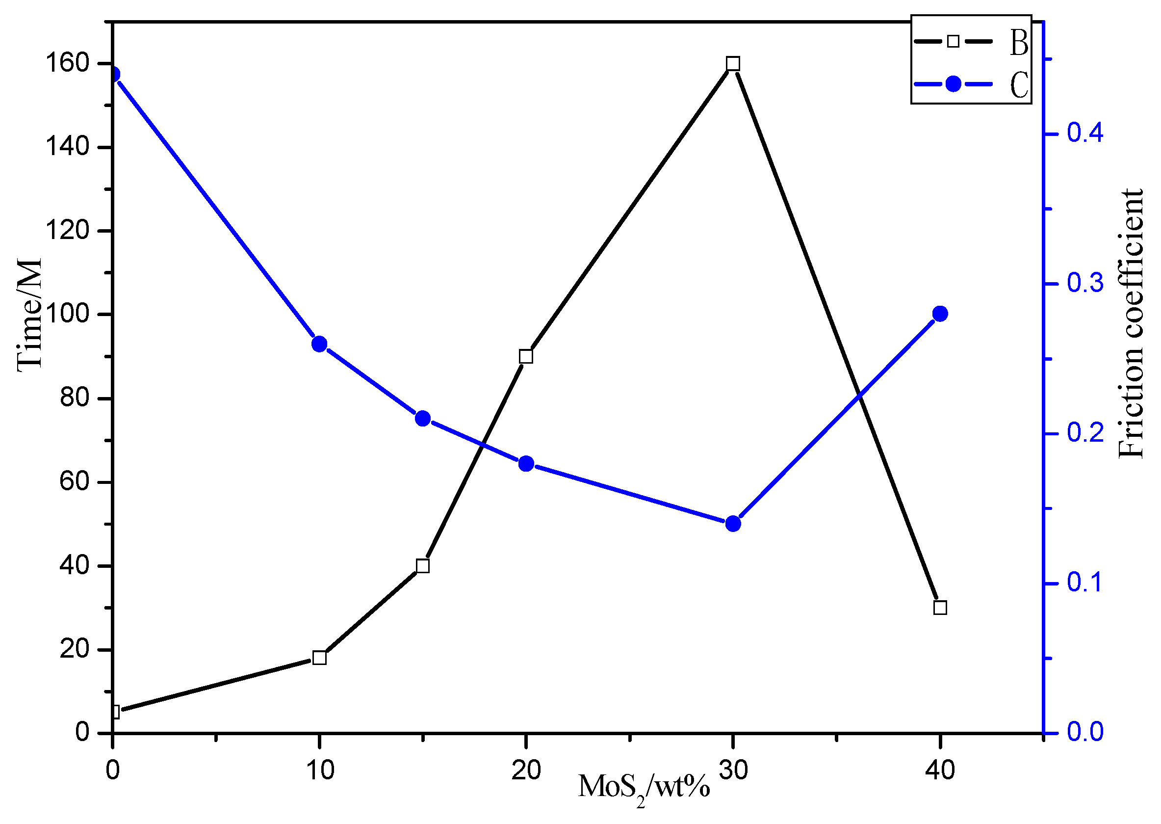
3.3.2. Effect of Different MoS2 Content on Coating Friction Performance

As shown in Figure 6, the friction performance of the coating exhibited a nonlinear relationship with MoS2 content at room temperature.
When MoS2 content increased from 10% to 30%, the friction coefficient decreased from 0.25 to 0.14 (a reduction of 44%). When MoS2 content further increased to 40%, the friction coefficient rebounded to 0.29. The friction time initially increased and then decreased with MoS2 content, peaking at 160 min for the 30% MoS2 coating.

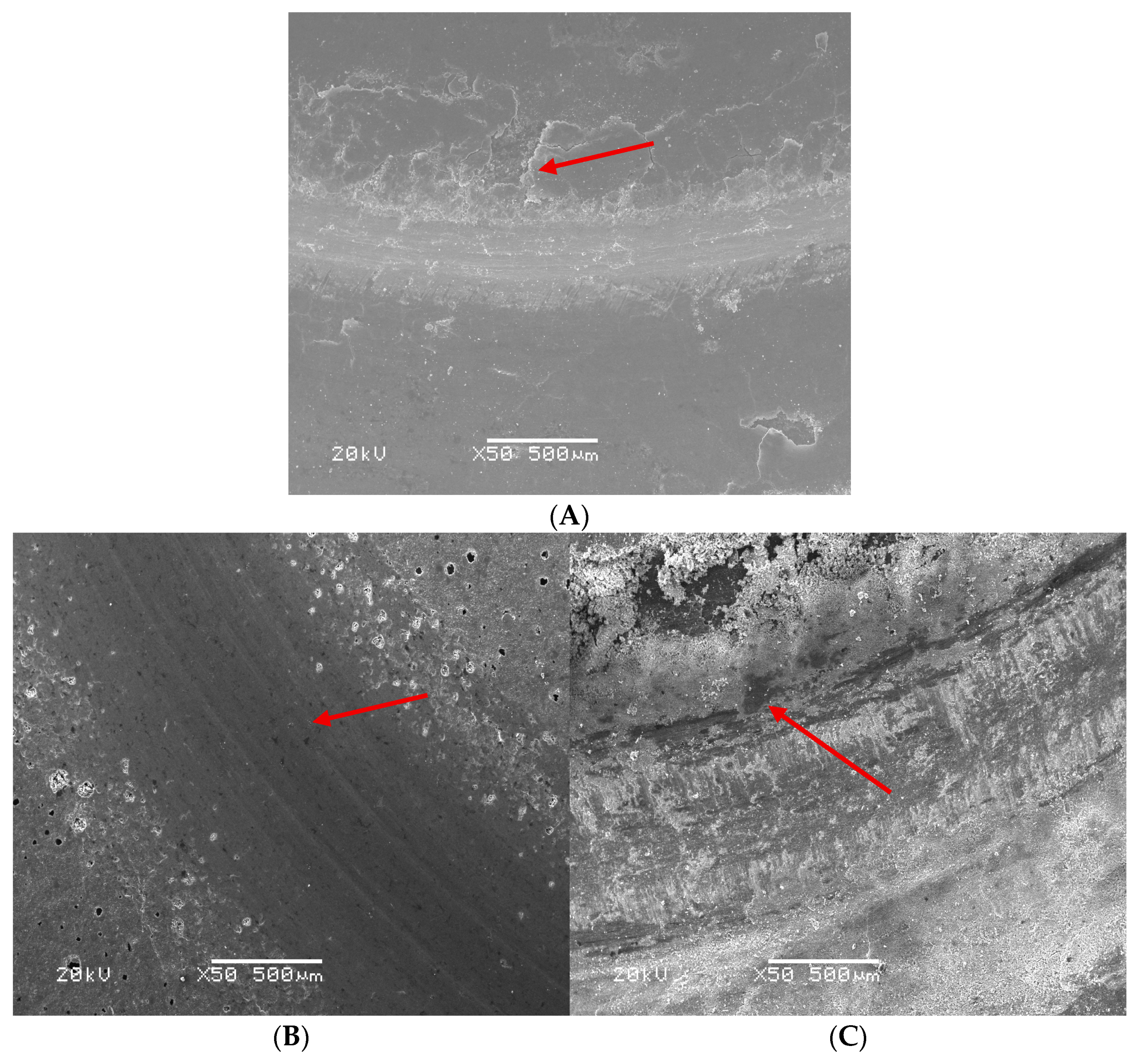
3.3.3. Friction Surface Analysis of Coatings with Different MoS2 Contents

Figure 7A–C show the surface morphology of coatings with 20%, 30%, and 40% MoS2 after friction testing at room temperature.
Integrated Analysis of MoS2 Content Effects on Coating Tribological Performance (Figure 7).
As shown in Figure 7A, when the MoS2 content is 20%, incomplete pore filling by MoS2 results in direct contact between matrix materials during friction, leading to adhesive wear. Significant cracks (indicated by arrows) appear on the coating surface due to the failure to form a continuous lubricating film, which reduces solid lubrication effectiveness. This lubrication failure triggers an abnormal increase in friction coefficient, inducing synergistic interaction between fatigue-wear and adhesive wear, ultimately accelerating coating failure.
As shown in Figure 7B, when the MoS2 content is 30%, a continuous lubricating film forms, and the layered structure of MoS2 reduces shear resistance. The worn surface becomes smooth, with minor abrasive wear scratches (indicated by arrows). When the lubricating film is damaged, fresh MoS2 particles replenish the contact zone, maintaining a low friction coefficient 0.14 and enhanced wear resistance.
As shown in Figure 7C, when the MoS2 content is 40%, agglomerated MoS2 particles (>50 μm) induce stress concentration, reducing mechanical strength. Surface spalling and severe abrasive wear (particle detachment, indicated by arrows) occur, elevating the friction coefficient to 0.29.

3.4. Effect of Graphite Content on Coating Performance

3.4.1. Effect of Graphite Content on Coating Microhardness

The phosphate binder was uniformly mixed with graphite powder and an appropriate amount of ZnO curing agent, sprayed onto the specimen surface, and cured in a 230 °C muffle furnace for 1 h. The microhardness of the coatings was tested, and the results are shown in Table 3.
When the graphite content increased to 20%, the microhardness reached a peak value of 81.51 HV. This is attributed to graphite particles (particle size: 1–5 μm) filling the pores in the binder, significantly improving coating density. When the graphite content exceeded 20%, excessive graphite particles detached due to insufficient encapsulation by the binder (binder content <80%), leading to a sharp decline in microhardness.

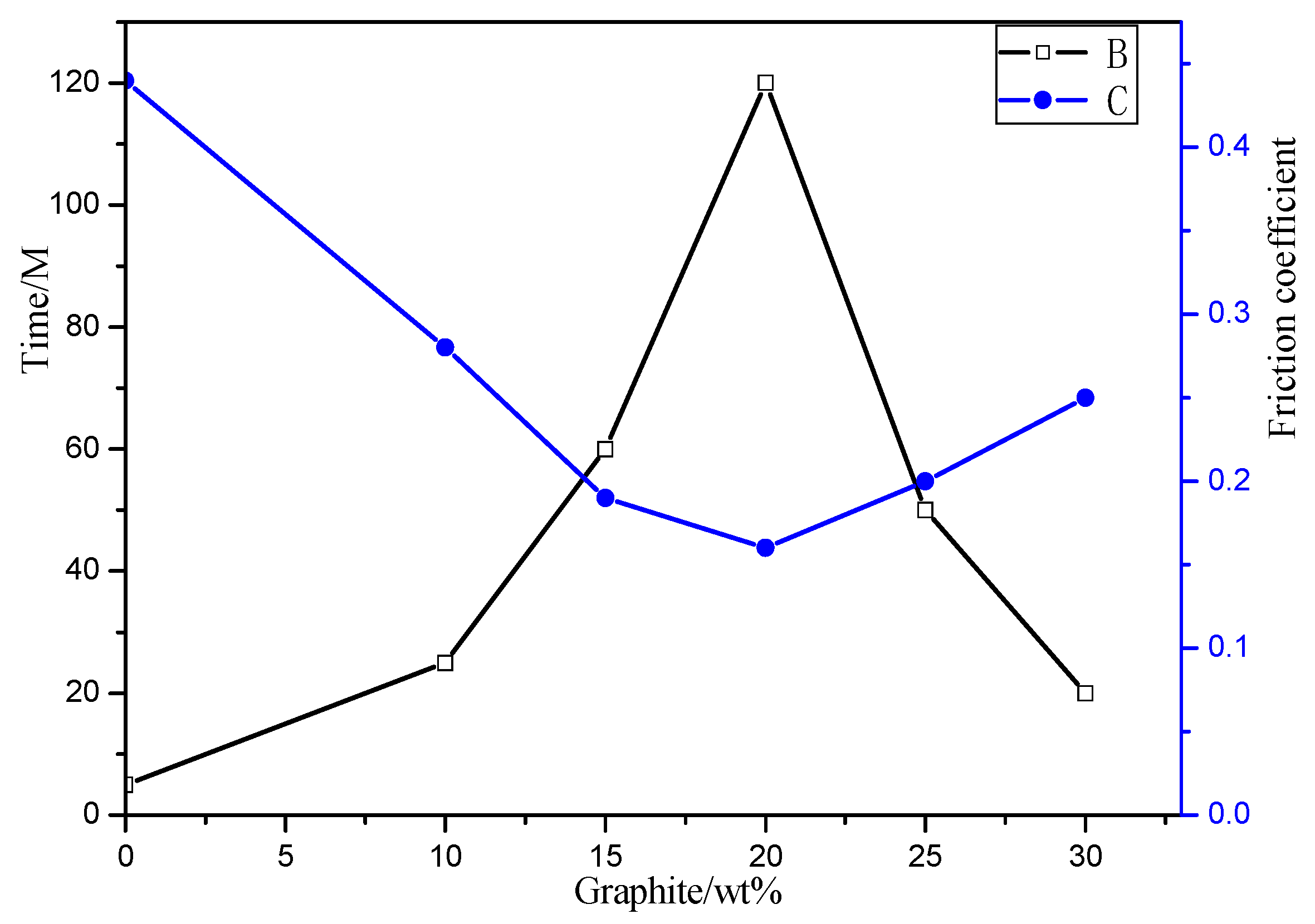
3.4.2. Effect of Graphite Content on Coating Friction Performance

As shown in Figure 8, the friction performance of the coating exhibits a nonlinear relationship with graphite content at room temperature.
When the graphite content increases from 10% to 20%, the friction coefficient decreases from 0.28 to 0.16 (a reduction of 42.86%). When the graphite content further increases to 30%, the friction coefficient rises to 0.25. At 20% graphite content, the friction time reaches 120 min, showing a 100% improvement compared to the 15% graphite group (60 min). At 30% graphite content, the friction time decreases to 75 min.

3.4.3. Friction Surface Analysis of Graphite-Containing Coatings

Figure 9A–C show the surface morphology of coatings with 10%, 20%, and 30% graphite after friction testing at room temperature.
Integrated Analysis of Graphite Content Effects on Coating Tribological Performance (Figure 9).
As shown in Figure 9A, when the graphite content is 10%, the lack of lubricating film continuity leads to direct contact between matrix materials at the friction interface, causing adhesive wear. Significant cracks (indicated by arrows) and fatigue crack propagation are observed on the coating surface. The incomplete lubricating film results in a friction coefficient of 0.28, which significantly accelerates surface delamination failure.
As shown in Figure 9B, when the graphite content is 20%, the layered structure of graphite reduces frictional resistance, forming a complete lubricating film. The worn surface exhibits characteristic fatigue-wear micropits and minor abrasive wear scratches (as indicated by arrows), with the friction coefficient reduced to 0.16.
As shown in Figure 9C, when the graphite content is 30%, detached graphite particles (>10 μm, indicated by arrows) act as abrasive media, intensifying wear. Due to the significantly lower density of graphite compared to MoS2, graphite occupies a larger volume under the same mass addition, effectively diluting the binder system and reducing the actual binder content. Consequently, the decreased binder content causes flaky spalling and fracture marks, lowering coating strength/hardness and increasing the friction coefficient to 0.25.

3.5. Synergistic Effect of Graphite and MoS2 on Coating Friction Performance

3.5.1. Experimental Design

The study of the effects of adding MoS2 and graphite separately on the coating’s friction performance at room temperature revealed that the coating achieved optimal tribological performance when the MoS2 content was 30% and the graphite content was 20%. Aluminum powder was added primarily to enhance the high-temperature resistance of the coating. The coating process was optimized through orthogonal experiments (Table 4), and the optimal formulation was determined (Table 5 and Table 6).
Figure 10A–C show the SEM morphological characteristics of three coatings (samples 1, 4, and 8 from Table 5) after friction testing at room temperature. Low solid lubricant content resulted in the absence of a continuous lubricating film on the friction surface, leading to poor lubrication and short friction time (Figure 10A). Numerous cracks and localized spalling were observed on the friction surface (indicated by the arrows in the image), indicating fatigue wear and adhesive wear. A well-formed lubricating film reduced direct contact between sliding surfaces (Figure 10B). Fine scratches on the coating surface suggested abrasive wear characteristics (indicated by the arrows in the image). Increasing the solid lubricant content reduced the proportion of the binder, weakening the coating’s bonding strength (Figure 10C). This caused particles to detach from the coating (indicated by the arrows in the image), generating abrasive particles.
These particles disrupted the formation of a complete lubricating film during friction, resulting in severe wear and shortened friction time.

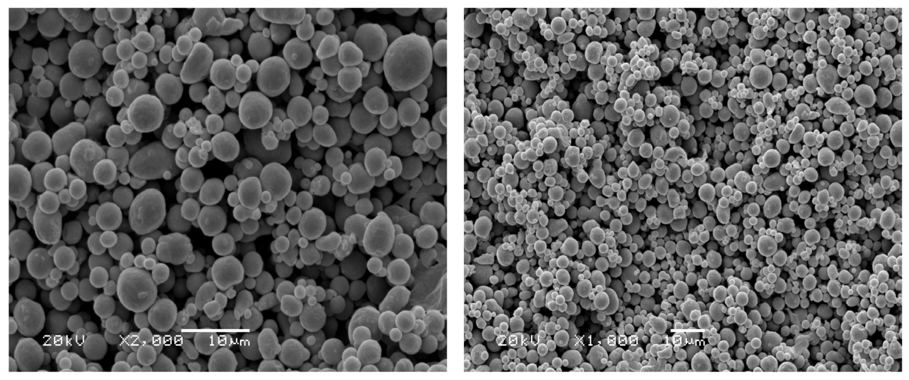
3.5.2. SEM Morphology Analysis of Composite Coatings

Composite coatings were prepared using the optimal formulation (A2: B1: C2: D2) with phosphate binder, aluminum powder, MoS2, graphite, and additives (ZnO and Tween 80). The SEM morphology of the coatings was analyzed at 25 °C, 300 °C, and 500 °C.
Figure 11 shows the surface SEM morphology of phosphate-based composite coatings at different sintering temperatures. Figure 11A (25 °C): The coating exhibited numerous pores and a rough surface (indicated by the arrows in the image). Figure 11B (300 °C): As the sintering temperature increased to 300 °C, partial removal of adsorbed and crystalline water reduced porosity and improved density. In contrast, the coating surface sintered at 500 °C (Figure 11C) exhibited significantly higher density. This was due to the substantial removal of adsorbed water and crystalline water, which enhanced the crosslinking degree of the phosphate network, while substrate pores were largely filled by filler particles. The improved compactness originated from the formation of a “ceramic–phosphate” composite phase via MoO3 (generated by MoS2 oxidation) and Al2O3 (formed by aluminum powder oxidation). Additionally, the layered structures of graphite and MoS2 synergistically facilitated sliding, suppressing adhesive wear and reducing abrasive particle generation.
In summary, after treatment at different temperatures, the binder matrix of the phosphate-based composite coating undergoes a series of phase transformations from aluminum phosphate to aluminum metaphosphate and aluminum pyrophosphate, forming an interconnected Al–O–P network structure. Composite fillers such as aluminum, graphite, and MoS2 effectively occupied the cross-linked network, reducing porosity at high temperatures and strengthening the Al–O–P cross-linked structure, thereby enhancing the coating’s density and thermal stability.

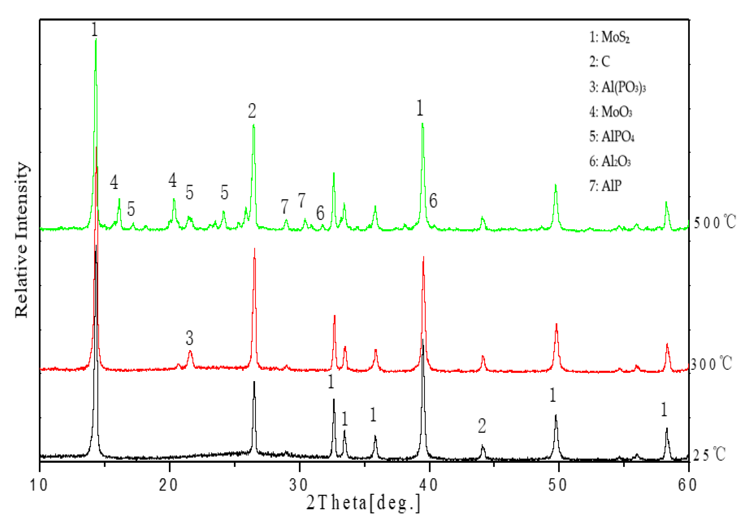
3.5.3. XRD Analysis of Coatings at Different Temperatures

Figure 12 indicates that the coating is primarily composed of MoS2 and graphite phases at 25 °C. As the temperature increases to 300 °C, the Al(H2PO4)3 phase in the binder undergoes gradual hydrolysis and condensation, transforming into a cross-linked network structure of Al(PO3)3. This enhances the cross-linking properties of the system, enabling the coating’s cohesive performance to be fully utilized at high temperatures. When the temperature reaches 500 °C, MoO3 peaks appear due to the oxidative decomposition of MoS2. Concurrently, the binder undergoes further crystalline phase transitions, forming AlPO4. The thermal dehydration of the coating induces a series of phase transitions (aluminum phosphate–aluminum metaphosphate–aluminum pyrophosphate), resulting in an interconnected Al–O–P network structure. The coating maintains stable performance in high-temperature environments up to 500 °C, demonstrating excellent heat resistance and oxidation resistance. Additionally, it produces no harmful substances during production or use, ensuring minimal environmental impact.

3.6. Friction Performance of Composite Coatings at Different Temperatures

The composite coating was cured in a 230 °C muffle furnace for 1 h, and its friction performance was tested at 25 °C, 300 °C, and 500 °C.
As shown in Figure 13, the phosphate coating with simultaneous addition of graphite and MoS2 at room temperature exhibited nearly twice the room-temperature friction duration compared to coatings with a single lubricant, achieving a minimum friction coefficient of 0.12 and a friction time of 260 min, demonstrating the synergistic friction effect between these two solid lubricants. At 500 °C, the friction coefficient was 0.24, and the friction time reached 40 min. The coating effectively resisted mechanical friction and wear at high temperatures, reducing frictional losses in mechanical components and thereby prolonging the service life of the protected materials.
The analysis revealed two key reasons for the doubled friction coefficient at 500 °C compared to 300 °C and the significantly reduced wear resistance:
Oxidation-induced lubricant degradation: As shown in Figure 5’s TG–DSC curves, MoS2 and graphite begin oxidizing at 315 °C and 325 °C, respectively. Their layered structures disintegrate, losing lubricating functionality and becoming unable to replenish worn areas in time.
Structural embrittlement: At 500 °C, the coating forms an Al–O–P network structure. While this increases hardness (e.g., Al2O3 and MoO3 formation), it also causes significantly reduced toughness, leading to brittle spalling and accelerated wear.
This dual mechanism—lubricant failure coupled with hardness-toughness imbalance—drives the friction coefficient surge and shortens service life.

4. Conclusions

  • The synergistic combination of MoS2 (30%) and graphite (20%) significantly enhances lubricating film continuity through shear slippage of layered materials and pore-filling effects, reducing the room-temperature friction coefficient by 20% compared to single-component coatings and extending wear resistance to 260 min. SEM analysis confirms that the formation of a continuous lubricating film effectively suppresses adhesive and abrasive wear.
  • At 500 °C, the coating undergoes sequential phase transitions (aluminum phosphate–aluminum metaphosphate–aluminum pyrophosphate), forming a three-dimensional Al–O–P cross-linked framework. Concurrently, the oxidation of MoS2 into MoO3 and aluminum into Al2O3 constructs a “ceramic–phosphate” composite phase, improving coating density and oxidation resistance.
  • Orthogonal experiments confirmed that a binder/filler ratio of 6:4 balances mechanical strength and thermal stability, while 10% aluminum powder content optimizes adhesion and prevents brittleness caused by excessive addition.
  • The preparation process of this coating is environmentally friendly, suitable for surface protection of high-temperature industrial equipment, and holds potential for large-scale application in fields such as the petrochemical and power industries.
  • Future research could explore novel lubricants (e.g., h-BN, graphene) and advanced deposition technologies, combined with computational optimization of formulations to expand coating applications under extreme operating conditions. Additionally, validating long-term stability, environmental compatibility, and industrial adaptability would facilitate the engineering implementation of high-performance eco-friendly coatings.

Author Contributions

Conceptualization, Y.D.; methodology, S.W.; validation, Y.Z.; formal analysis, Y.D.; investigation, H.L.; resources, Y.Z.; data curation, H.L.; writing—original draft, Y.D.; writing—review and editing, B.Y.; supervision, B.Y.; project administration, S.W.; funding acquisition, S.W. All authors have read and agreed to the published version of the manuscript.

Funding

This work was financially supported by the Qinghai Institute of Technology in support of the “Kunlun Talent” Talent Introduction Research Project (2023-QLGKLYCZX-018).

Institutional Review Board Statement

Not applicable.

Informed Consent Statement

Not applicable.

Data Availability Statement

Data will be made available on request.

Conflicts of Interest

The authors declare no conflicts of interest.

References

  1. Xiong, X.H.; Lv, Z.M.; Tan, H.Z.; Wei, B. A typical Super-Heater tube leakage and high temperature corrosion mechanism investigation in a 260 t/h circulated fluidized boiler. Eng. Fail. Anal. 2020, 109, 104255. [Google Scholar] [CrossRef]
  2. Zhang, X.J.; Liu, H.; Chen, T.Z.; Wang, G.Y.; Li, H.Y.; Hu, H.Y.; Yu, Y.; Yao, H. Application of coatings to alleviate fireside corrosion on heat transfer tubes during the combustion of Low-Grade solid fuels: A review. Energy. Fuels. 2020, 34, 11752–11770. [Google Scholar] [CrossRef]
  3. Niu, Y.Q.; Tan, H.Z.; Hui, S.E. Ash-Related issues during biomass combustion: Alkali-Induced slagging, silicate Melt-Induced slagging (ash fusion), agglomeration, corrosion, ash utilization, and related countermeasures. Prog. Energ. Combust. 2016, 52, 1–61. [Google Scholar] [CrossRef]
  4. Nagarajan, R.; Ambedkar, B.; Gowrisankar, S.; Somasundaram, S. Development of predictive model for Fly-Ash erosion phenomena in Coal-Burning boilers. Wear 2009, 267, 122–128. [Google Scholar] [CrossRef]
  5. Ramteke, M.S.; Walczak, M.; Stefano, D.M.; Ruggiero, A.; Rosenkranz, A.; Marian, M. 2D materials for Tribo-corrosion and oxidation protection. Adv. Colloid. Interface 2024, 331, 103243. [Google Scholar] [CrossRef]
  6. Lv, Y.Z.; Sun, Y.N.; Deng, C.M.; Fan, X.J.; Li, S.J.; Wang, C.; Yang, Y.Q.; Zhang, Y.H.; Chun, Y. Preparation, corrosion and tribological properties evolution of Self-Lubricating Al2O3-TiO2 coatings with superior Anti-Corrosion. Surf. Coat. Technol. 2025, 498, 131849. [Google Scholar] [CrossRef]
  7. Zhu, H.M.; Li, B.C.; Chen, M.H.; Qiu, C.J.; Tang, Z.F. Improvement of Corrosion Resistance of Hastelloy-N Alloy in LiF-NaF-KF Molten Salt by Laser Cladding Pure Metallic Coatings. Coatings 2018, 8, 322. [Google Scholar] [CrossRef]
  8. Vasile, S.B.; Birca, C.A.; Surdu, A.V.; Surdu, A.V.; Neacsu, A.I.; Nicoară, A.I. Ceramic Composite Materials Obtained by Electron-Beam Physical Vapor Deposition Used as Thermal Barriers in the Aerospace Industry. Nanomaterials 2020, 10, 370. [Google Scholar] [CrossRef]
  9. Li, C.Y.; Quan, G.N.; Zhang, Q.; Wang, X.H.; Li, X.C.; Kou, S.Z. A Novel Amorphous Alloy Coating for Elevating Corrosion Resistance of X70 Pipeline Steel. Therm. Spray. Technol. 2024, 33, 1612–1629. [Google Scholar] [CrossRef]
  10. Patel, D.; Bhatt, P.; Bateriwala, R. Thermal Spray Techniques for Developing a Carbide Coating. Int. J. Innov. Technol. Explor. Eng. 2019, 8, 692–700. [Google Scholar]
  11. Monette, Z.; Kasar, A.K.; Daroonparvar, M.; Menezes, P.L. Supersonic particle deposition as an additive technology: Methods, challenges, and applications. Int. J. Adv. Manuf. Technol. 2020, 106, 2079–2099. [Google Scholar] [CrossRef]
  12. Ralls, A.M.; Daroonparvar, M.; Sikdar, S.; Rahman, M.H.; Monwar, M.; Watson, K.; Kay, C.M.; Menezes, P.L. Tribological and corrosion behavior of high pressure cold sprayed duplex 316 L stainless steel. Tribol. Int. 2022, 169, 107471. [Google Scholar] [CrossRef]
  13. Ralls, A.M.; Kasar, A.K.; Daroonparvar, M.; Siddaiah, A.; Kumar, P.; Kay, C.M.; Misra, M.; Menezes, P.L. Effect of gas propellant temperature on the microstructure, friction, and wear resistance of High-Pressure cold sprayed Zr7O2 coatings on Al6061 alloy. Coatings 2022, 12, 263. [Google Scholar] [CrossRef]
  14. Chen, P.J.; Xiao, P.; Li, Z.; Li, J.W. Oxidation properties of Tri-Layer Ytterbium-Disilicate/mullite/Silicon-Carbide environment barrier coatings for Cf/SiC composites. Surf. Coat. Technol. 2020, 402, 126329. [Google Scholar] [CrossRef]
  15. Fogliati, M.; Fontana, D.; Garbero, M.; Vanni, M.; Baldi, G.; Dondè, R. CFD simulation of paint deposition in an air spray process. JCT Res. 2006, 3, 117–125. [Google Scholar] [CrossRef]
  16. Zhang, S.M.; Wang, W.J.; Gao, Y.; Liang, K.; Cui, J.Y.; Yang, D.Y.; Zhu, K.; Ma, C.L.; Yuan, H.Y. Air pressure spray deposition of layer-by-layer calcium niobate nanosheets for efficient thermal insulation coatings. Ceram. Int. 2024, 50, 53899–53906. [Google Scholar] [CrossRef]
  17. Shi, M.J.; Li, X.H.; Jiang, Y.D.; Li, S.X.; Li, B.W.; Zhang, S.J.; Nan, C.W. 2D Nanosheet Spray Coating for Scalable Processing of High-Energy-Density Dielectric Polymer Films. Adv. Electron. Mater. 2023, 9, 53899–53906. [Google Scholar] [CrossRef]
  18. Donnet, C.; Erdemir, A. Historical developments and new trends in tribological and solid lubricant coatings. Surf. Coat. Technol. 2003, 180, 76–84. [Google Scholar] [CrossRef]
  19. Bartuli, C.; Valente, T.; Casadei, F.; Tului, M. Advanced thermal spray coatings for tribological applications. Proc. Inst. Mech. Eng. Part L J. Mater. Des. Appl. 2007, 221, 175–185. [Google Scholar] [CrossRef]
  20. Manh, C.L.; Huong, T.L. The Study’s Chemical Interaction of the Sodium Silicate Solution with Extender Pigments to Investigate High Heat Resistance Silicate Coating. J. Anal. Methods. Chem. 2021, 2021, 5510193. [Google Scholar]
  21. Cao, X.Q.; Zhao, K.L.; Wang, L.; Wang, T.T.; Wu, Y.Z.; Tang, X.P.; Bai, J.W.; Zhang, C.H.; Liu, W.X.; Cao, W.X.; et al. Robust, hermally insulating, and High-Temperature resistant Phosphate-Enhanced mullite fiber porous ceramic composites. Ceram.Int. 2024, 50, 23733–23743. [Google Scholar] [CrossRef]
  22. Chung, D.D.L. Acid aluminum phosphate for the binding and coating of materials. J. Mater. Sci. 2003, 38, 2785–2791. [Google Scholar] [CrossRef]
  23. Ye, Y.P.; Zhou, H.D.; Jia, J.H.; Chen, J.M. High temperature Anti-Sticking lubricating coating. CN98123517.4, 6 December 2000. (In Chinese). [Google Scholar]
  24. Yuan, H.; Wang, Y.S.; Liu, Z.Y.; Li, S.Y. A study on the properties and working mechanism of a waterborne Polyurethane-Modified Silicate-Based coating. RSC Adv. 2019, 9, 26817–26824. [Google Scholar] [CrossRef] [PubMed]
  25. Zhuang, W.H.; Li, H.; Li, W.; Fan, X.Q.; He, J.F.; Cai, Z.B.; Fu, W.; Zhang, G.G.; Wan, S.H.; Zhu, M.H. Probing fretting performance of DLC and MoS2 films under fluid lubrication. Appl. Surf. Sci. 2019, 478, 661–679. [Google Scholar] [CrossRef]
  26. Kong, X.; Liu, Y.; Chen, M.H.; Zhang, T.; Wang, T.H. High Temperature Oxidation and Tribological Behaviors of NiCrAl-Graphite Self-Lubricating Composite. Acta. Metal. Sin. 2021, 34, 900–912. [Google Scholar] [CrossRef]
  27. Yin, H.; Li, H.Y.; Chen, J.D.; Wang, Y.Y.; Zhang, S.W.; Xu, L.L.; Li, T.; Zeng, Z.W.; Tang, J.L. Research Progress and Application of Phosphate Coatings. Surf. Technol. 2021, 50, 232–241. [Google Scholar]
  28. Sarkar, M.; Mandal, N. Solid lubricant materials for high temperature application: A review. Mater. Today Proc. 2022, 66, 3762–3768. [Google Scholar] [CrossRef]
  29. Kumar, R.; Hussainova, I.; Rahmani, R.; Antonov, M. Solid Lubrication at High-Temperatures A review. Materials 2022, 15, 1695. [Google Scholar] [CrossRef]
  30. Dienwiebel, M.; Verhoeven, G.S.; Pradeep, N.; Frenke, J.W.M.; Heimberg, J.A.; Zandbergen, H.W. Superlubricity of graphite. Phys. Rev. Lett. 2004, 92, 126101. [Google Scholar] [CrossRef]
  31. De Lima, G.A.; Klein, A.N.; Furlan, K.P. Controlling the Solid-State Reaction in Fe-MoS2 Self-Lubricating Composites for Optimized Tribological Properties. Lubricants 2022, 10, 142. [Google Scholar] [CrossRef]
  32. Cho, M.H.; Ju, J.; Kim, S.J.; Jang, H. Tribological properties of solid lubricants (graphite, Sb2S3, MoS2) for automotive brake friction materials. Wear 2005, 260, 855–860. [Google Scholar] [CrossRef]
  33. Li, J.L.; Xiong, D.S. Tribological properties of Nickel-Based Self-Lubricating composite at elevated temperature and counterface material selection. Wear 2008, 265, 533–539. [Google Scholar] [CrossRef]
  34. Vippola, M.; Vuorinen, J.; Vuoristo, P.; Lepistö, T.; Mäntylä, T. Thermal analysis of plasma sprayed oxide coatings sealed with aluminium phosphate. J. Eur. Ceram. Soc. 2002, 22, 1937–1946. [Google Scholar] [CrossRef]
  35. Han, H.J.; Kim, D.P. Studies on Curing Chemistry of Aluminum-Chromium-Phosphates as Low Temperature Curable Binders. J. Sol-Gel. Sci. Techn. 2003, 26, 223–228. [Google Scholar] [CrossRef]
  36. Maier, C.R.; Jones, L.E. The influence of aluminum phosphates on graphite oxidation. Carbon 2005, 43, 2272–2276. [Google Scholar] [CrossRef]
  37. Sliney, H.E. Solid lubricant materials for high temperatures-a review. Tribol. Int. 1982, 15, 303–315. [Google Scholar] [CrossRef]
  38. Serpini, E.; Rota, A.; Ballestrazzi, A.; Marchetto, D.; Gualtieri, E.; Valeri, S. The role of humidity and oxygen on MoS2 thin films deposited by RF PVD magnetron sputtering. Surf. Coat. Technol. 2017, 319, 345–352. [Google Scholar] [CrossRef]
  39. Jeurgens, L.P.H.; Sloof, W.G.; Tichelaar, F.D.; Mittemeijer, E.J. Growth kinetics and mechanisms of Aluminum-Oxide films formed by thermal oxidation of aluminum. J. Appl. Phys. 2002, 92, 1649–1656. [Google Scholar] [CrossRef]
Figure 1. SEM morphology of aluminum powder.
Coatings 15 00704 g001
Figure 2. SEM morphology of MoS2.
Coatings 15 00704 g002
Figure 3. SEM morphology of graphite.
Coatings 15 00704 g003
Figure 4. Process flowchart of coating preparation.
Coatings 15 00704 g004
Figure 5. TG–DSC curves of the coating in air atmosphere. (A) TG curves; (B) DSC curves. 1. Al(H2PO4)3; 2. Al(H2PO4)3/5% C; 3. Al(H2PO4)3/5% MoS2; 4. Al(H2PO4)3/5% Al.
Coatings 15 00704 g005
Figure 6. The effect of different MoS2 content on the wear resistance of the coating. B: friction time; C: friction coefficient.
Coatings 15 00704 g006
Figure 7. Wear surface morphology of MoS2 coatings with different content. (A) 20%, (B) 30%, (C) 40%.
Coatings 15 00704 g007
Figure 8. Effect of different content of graphite on the wear resistance of the coating. B: friction time, C: friction coefficient.
Coatings 15 00704 g008
Figure 9. Wear surface morphology of coatings with different graphite content. (A) 10%, (B) 20%, (C) 30%.
Coatings 15 00704 g009
Figure 10. Wear surface morphology of different coatings: (A) number 1, (B) number 4, (C) number 8.
Coatings 15 00704 g010
Figure 11. SEM morphology of phosphate-based composite coating surface at different sintering temperatures. (A) 25 °C; (B) 300 °C; (C) 500 °C.
Coatings 15 00704 g011
Figure 12. XRD patterns of coatings at different friction temperatures.
Coatings 15 00704 g012
Figure 13. Friction performance of coating (number 4) at different temperatures (B: friction time, C: friction coefficient).
Coatings 15 00704 g013
Table 1. Adhesion of coatings with different aluminum powder content.
SamplePhosphate Binder Content (%)Aluminum Content (%)Adhesion
11000-
2991Level 4
3955Level 3
49010Level 1
58515Level 3
68020Level 5
Table 2. Add MoS2 coating microhardness.
SamplePhosphate Binder Content (%)MoS2 Content (%)Average Microhardness of
Coating (HV)
11000-
2901038.26
3851545.53
4802058.18
5703079.23
6604024.36
Table 3. Add Graphite coating microhardness.
SamplePhosphate Binder Content (%)Graphite Content (%)Average Microhardness of Coating (HV)
11000-
2901046.52
3851557.12
4802081.51
5752553.38
6703036.28
Table 4. Orthogonal experiment.
LevelFactors
A
(Binders:Fillers)
B
(Graphite %)
C
(MoS2%)
D
(Aluminum Powder %)
17:35105
26:4101510
35:5152015
Table 5. L9(34) Analysis of orthogonal sample results.
NumberA
(Binders:Fillers)
B
(Graphite %)
C
(MoS2%)
D
(Aluminum Powder %)
Friction Time
yi (min)
1234
11111y1 = 30
21222y2 = 80
31333y3 = 40
42123y4 = 260
52231y5 = 180
62312y6 = 200
73132y7 = 140
83213y8 = 90
93321y9 = 110
Table 6. Orthogonal statistical analysis.
Statistical MeasureA
(Binders:Fillers)
B
(Graphite %)
C
(MoS2%)
D
(Aluminum Powder %)
K1 (Level 1 Sum)150430320320
K2 (Level 2 Sum)640350450420
K3 (Level 3 Sum)340350360390
Avg .   K ¯ 1 50143107107
Avg .   K ¯ 2 213117150140
Avg .   K ¯ 3 113117120130
Rj (Range)163264333
Optimal LevelA2 (6:4)B1 (5%)C2 (15%)D2 (10%)
The optimal coating parameters are as follows: binder–filler = 6:4; graphite content = 5%; MoS2 content = 15%; aluminum powder content = 10%.
Disclaimer/Publisher’s Note: The statements, opinions and data contained in all publications are solely those of the individual author(s) and contributor(s) and not of MDPI and/or the editor(s). MDPI and/or the editor(s) disclaim responsibility for any injury to people or property resulting from any ideas, methods, instructions or products referred to in the content.

