Article

An Exploration of Manufacturing Technology to Refine the Grain Size and Improve the Properties of Welded TA1 Titanium Plates for Cathode Rollers

1
School of Materials Science and Engineering, Changzhou University, Changzhou 213164, China
2
Huaide College, Changzhou University, Jingjiang 214500, China
3
Changzhou Sinosteel Precision Forging Materials Co., Ltd., Changzhou 213165, China
4
Restoration Department, Changzhou Stomatological Hospital, Changzhou 213003, China
5
Northwest Institute for Nonferrous Metal Research, Xi’an 710016, China
*
Author to whom correspondence should be addressed.
Coatings 2025, 15(6), 687; https://doi.org/10.3390/coatings15060687
Submission received: 16 April 2025 / Revised: 29 May 2025 / Accepted: 3 June 2025 / Published: 6 June 2025

Abstract

:
Electrolytic copper foil is one of the core materials in the fields of electronics, communications, and power. The cathode roller is the key component of the complete set of electrolytic copper foil equipment, and the quality of the titanium cylinder of the cathode roller directly determines the quality of the electrolytic copper foil. There typically exists a longitudinal weld on the surface of the cathode roller’s titanium cylinder sleeve manufactured by the welding method, which leads to the degradation of the quality of the electrolytic copper foil. Refining the grains in the weld zone and the heat-affected zone to close to those of the base material is a key solution for the manufacturing of welded cathode rollers. In order to effectively modify the microstructure and obtain an optimal refining effect in the weld zone of a TA1 cathode roller, a novel composite technology consisting of low-energy and fewer-pass welding combined with multi-pass rolling deformation and vacuum annealing treatment was primarily explored for high-purity TA1 titanium plates in this study. The microstructure of each area of the weld was observed using the DMI-3000M optical microscope, and the hardness was measured using the HVS-30 Vickers hardness tester. The research results show that the microstructure of each area of the weld can be effectively refined by using the novel composite technology of low-energy and fewer-pass welding, multi-pass rolling deformation, and vacuum annealing treatment. Among the explored experimental conditions, the optimal grain refinement effect is obtained with a V-shaped welding groove and four passes of welding with a welding current of 90 A and a voltage of 8–9 V, followed by 11 passes of rolling deformation with a total deformation rate of 45% and, finally, vacuum annealing at 650 °C for 1 h. The grain size grades in the weld zone and the heat-affected zone are close to those of the base material, namely grade 7.5~10, grade 7.5~10, and grade 7.5~10 for the weld zone, heat-affected zone, and base material, respectively. Meanwhile, this technology can also refine the grains of the base material, which is conducive to improving the overall mechanical properties of the titanium plate.

1. Introduction

Electrolytic copper foil is one of the most important materials in lithium-ion batteries (LIB), printed circuit boards (PCB), and chip packaging substrates (CPS) [1,2,3,4]. Currently, according to the different production methods of copper foil, it can generally be divided into two major categories: rolled copper foil and electrolytic copper foil. Rolled copper foil is an ingot formed by melting and casting pure copper. Subsequently, the base material is prepared through a series of processes such as hot pressing and cold pressing in a high-precision pressing mill to obtain the required copper foil thickness and quality. Electrolytic copper foil is manufactured through the electrochemical deposition of copper ions in an electrolyte solution [5,6]. Compared with the disadvantages of rolled copper foil, such as the complex production process, stringent equipment requirements, low production efficiency, and high cost, electrolytic copper foil has the following advantages: a simple production process, a minimal equipment cost, easy control of the foil thickness, high production efficiency, and a reduced total cost.
With the rapid development of downstream technologies, the demand for upstream electrolytic copper foil has increased year by year. In particular, the requirements for the quality and performance of copper foil are growing continuously. The cathode roller, a key piece of equipment in copper foil manufacturing, enables the electrode positioning of copper foil on its surface—a process that essentially extends the microstructure of the roller’s substrate [7,8]. The microstructure of the cathode roller is closely related to the grade and quality of the copper foil, thus playing a decisive role in producing high-quality copper foil.
At present, there are two main methods for the manufacturing of cathode rollers, which are spinning (seamless) and welding (seamed) [9,10]. Compared with the welding manufacturing method, the production cycle of the spinning method is much longer, and the costs are much higher. Moreover, the spinning equipment and molds for the manufacturing of cylinder sleeves with large diameters are more costly or even impossible to obtain. Meanwhile, the preparation of titanium cylinder sleeves for cathode rollers via the welding method has the advantages of a lower cost, higher production efficiency, and no limitation on the diameter of the titanium cylinder sleeves. Therefore, in the manufacturing of titanium cathode rollers with large diameters, the welding manufacturing method provides outstanding advantages [11,12]. However, there typically exists a longitudinal weld on the surface of the cathode roller’s titanium cylinder sleeve when using the welding method. This brings about a bright band at the corresponding position on the copper foil material, resulting from the presence of the longitudinal weld, which seriously affects the quality of the copper foil and restricts the production efficiency. This is because the grain boundaries on the surface have a great influence on the electrode positioning of copper ions, mainly due to their inherent defect characteristics [13,14]. Therefore, a key solution in the production of welded cathode rollers is to develop an appropriate method to regulate the microstructure of the weld-related zone and obtain a microstructure with almost the same grain size as the base material, thus avoiding the bright band at the corresponding position of the longitudinal weld.
Due to the above problem of the bright band, strict requirements have been put forward regarding the grain size and uniformity of cathode rollers manufactured via the welding method in the industrial production of electrolytic copper foil. In order to meet these high requirements, many studies have been conducted to refine the microstructure in the weld zone, and the goal is to solve the problem of the bright band existing at the corresponding position of the copper foil material [15,16]. Sun et al. [17] introduced a large number of martensite structures to the surface of the titanium cathode through selective laser melting, thereby increasing the density of the grain boundaries. Won-Bin [18] selected appropriate ranges for the welding process parameters for the cathode roller through thermoelastic–plastic analysis and used a series of welding variables obtained from an analysis of optimization algorithms. However, his research has almost no practical value in the real production of cathode rollers, since too few welding variables were considered and it was not based on engineering applications. Wu [19] proposed a novel fast-frequency pulsed tungsten inert gas (FFP-TIG) welding technology, which introduces a high-frequency pulsed current into TIG welding to achieve the goal of refining the microstructure of Ti-6Al-4V welds. However, this method is not popular and has a relatively high production cost; thus, it is challenging to promote and apply. Zongshi Hou [20] reported a method that involves repeatedly heating, forging, and hammering the cathode roller weld seam and heat-affected zone to modify the microstructure in the weld zone, resulting in an equiaxed structure similar to that of the base material. However, while heating the weld zone, it is necessary to keep the base material cool; thus, this method is complex and challenging to apply in cathode rollers with large diameters. Xu [21] adopted post-welding annealing and sandblasting treatment, which was beneficial in refining the microstructure in the weld zone, but the sandblasting treatment only refined the grains on the surface layer of the cathode roller.
Therefore, the reported and existing technologies cannot effectively and conveniently solve the problem of the bright band resulting from the longitudinal weld due to the presence of microstructures with large grain sizes [11,12]. In this study, in order to promote the application of the welding method for the manufacturing of cathode roller titanium cylinder sleeves, different welding variables, including the welding groove, energy, and pass, are adopted. Moreover, severe deformation in the weld zone caused by different deforming methods followed by annealing is primarily explored in this study. The research goal is to develop a novel technology to effectively regulate the microstructure of the weld zone and heat-affected zone of a TA1 titanium plate, obtain a microstructure close to that of the base material, and thus promote the application of the welding method in the manufacturing of cathode rollers.

2. Materials and Methods

A TA1 titanium plate with high purity was selected as the material for this research, and its composition is presented in Table 1, while its mechanical properties are listed in 
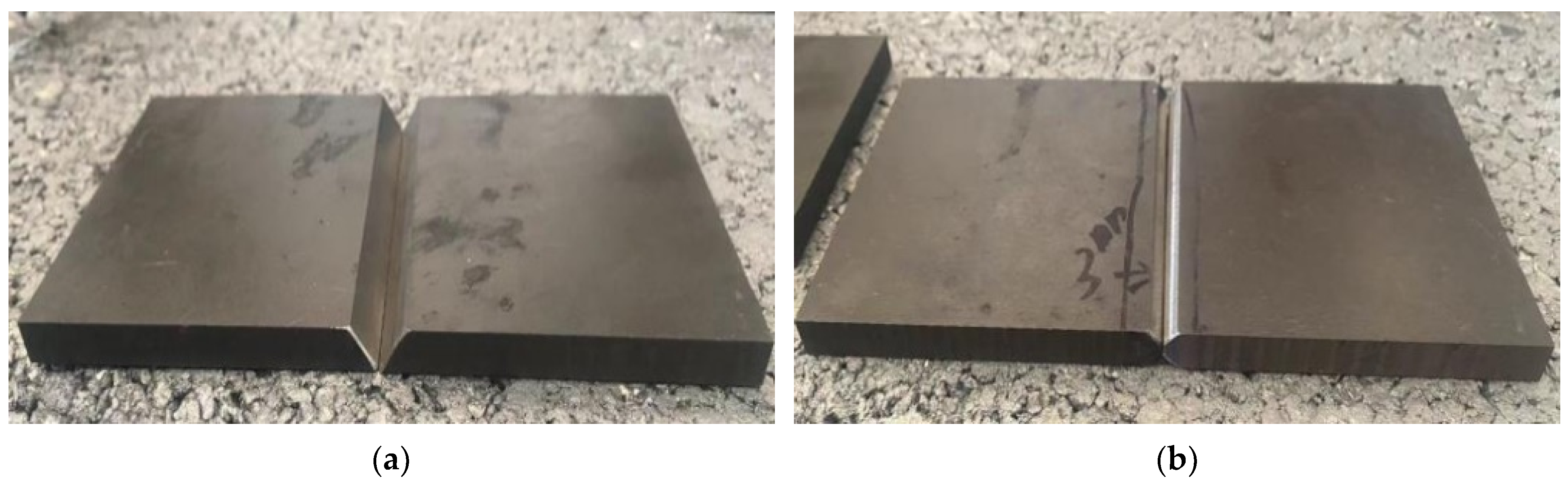
Table 2. Samples with dimensions of 80 mm × 30 mm × 8 mm were fabricated using wire-cut electrical discharge machining (WEDM). Welding grooves with a V shape and X shape were machined using a milling machine, and the morphologies of the two types of welding grooves are shown in Figure 1, while their detailed dimensions are shown in Table 3. The welding method employed in this research was manual tungsten inert gas (TIG) welding, performed by a qualified employee. The material of the filler wire was identical to the plate material of TA1, with a diameter of 2 mm. Argon gas, with purity of 99.99%, was used as the shielding gas.
As is well known, a V-shaped groove has the following advantages: it is easier to machine, and there is no need to turn it over during the welding process, enabling single-sided welding. However, this type of groove is more prone to deformation after welding, especially for thin plates; thus, it is mainly employed for medium- and thick-plate welding. In contrast, an X-shaped groove can reduce the volume of the weld metal by approximately 50% at the same thickness as compared to a V-shaped groove. Additionally, symmetrical welding with an X-shaped groove results in less residual deformation after welding. Given the advantages and characteristics of the two types of welding grooves, both V-shaped and X-shaped grooves were selected and explored in this study.
Three comprehensive experiments involving various welding and deformation processes were designed and conducted on the samples, which are described below.
The first experiment: Both V-shaped and X-shaped grooves were used, and manual tungsten inert gas (TIG) welding was performed on titanium plates. The detailed welding parameters are shown in 
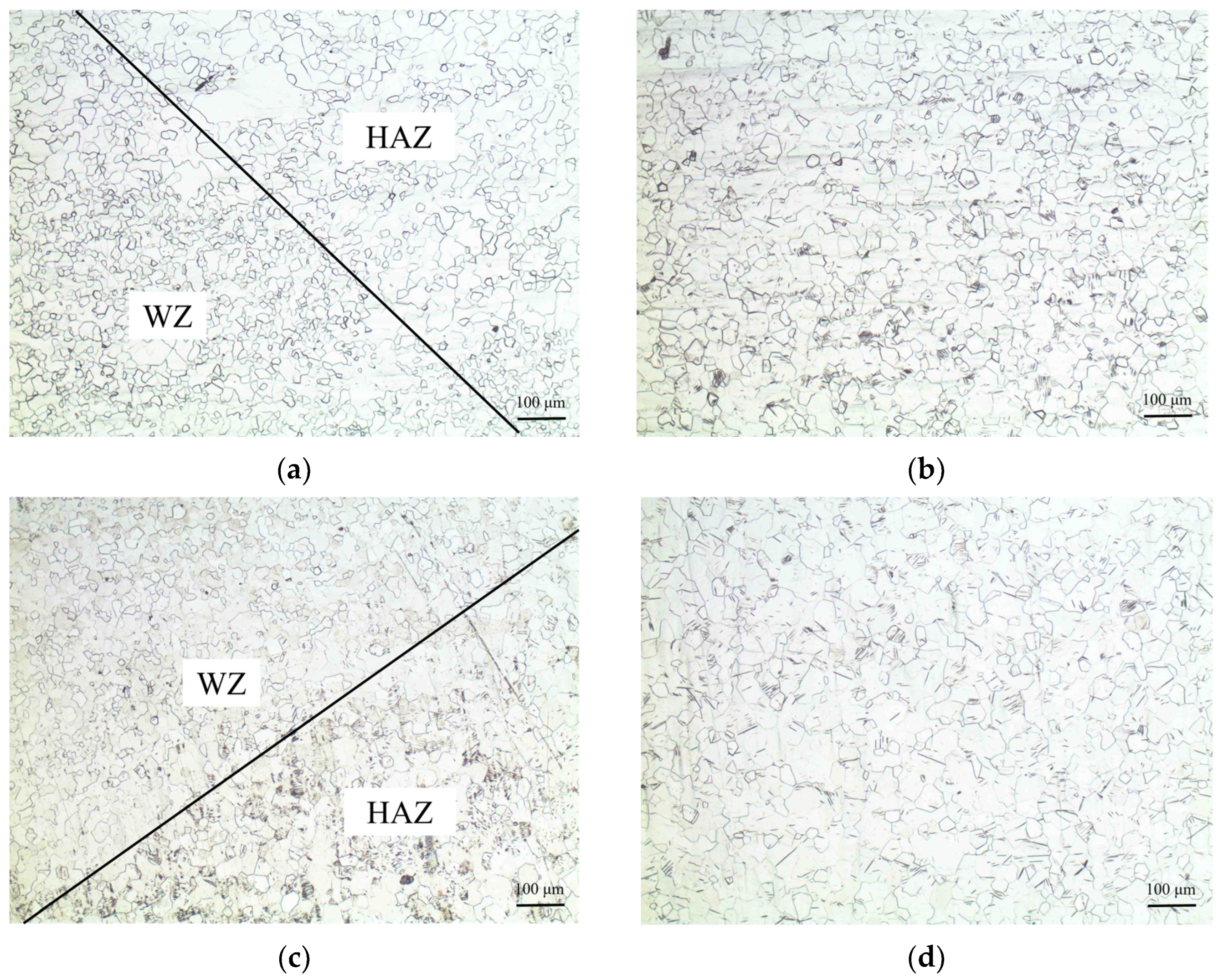
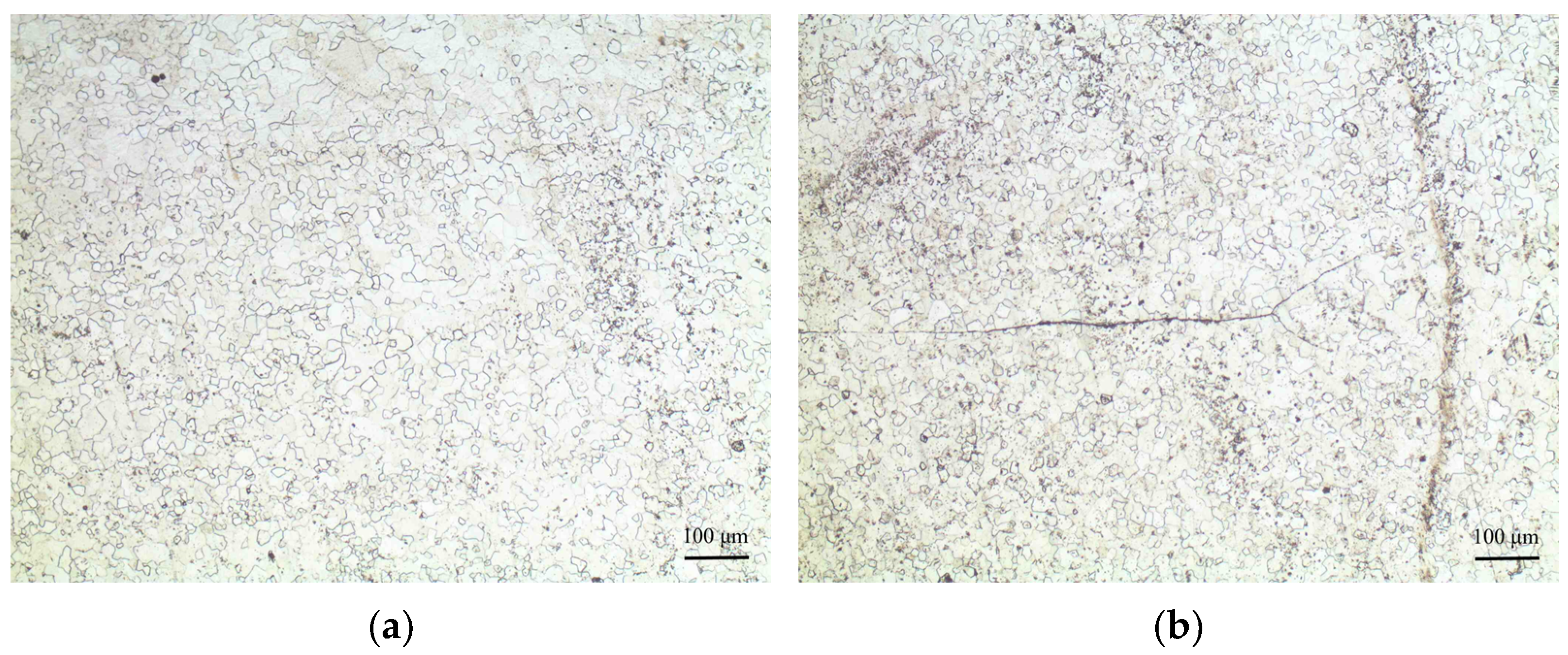
Table 4. Titanium plates with both types of grooves underwent the same number of welding passes, i.e., 12. Subsequently, the welded titanium plates were cold-pressed to 8 mm by a single operation using a 1600 T fast forging machine, with the thickness being consistent with that of the base material. In other words, the height of the weld bead was reduced by half, while the height of the base material remained unchanged.
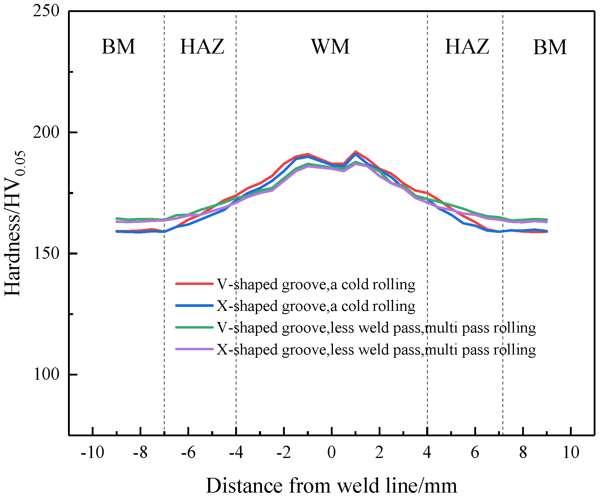
The second experiment: Both V-shaped and X-shaped grooves were used again, and almost the same procedure as in Experiment 1 was adopted. However, the number of welding passes was decreased to 5, and the number of rolling passes was increased to 4. The weld seam of the titanium plates underwent 45% rolling deformation, and the base metal experienced 21% deformation.
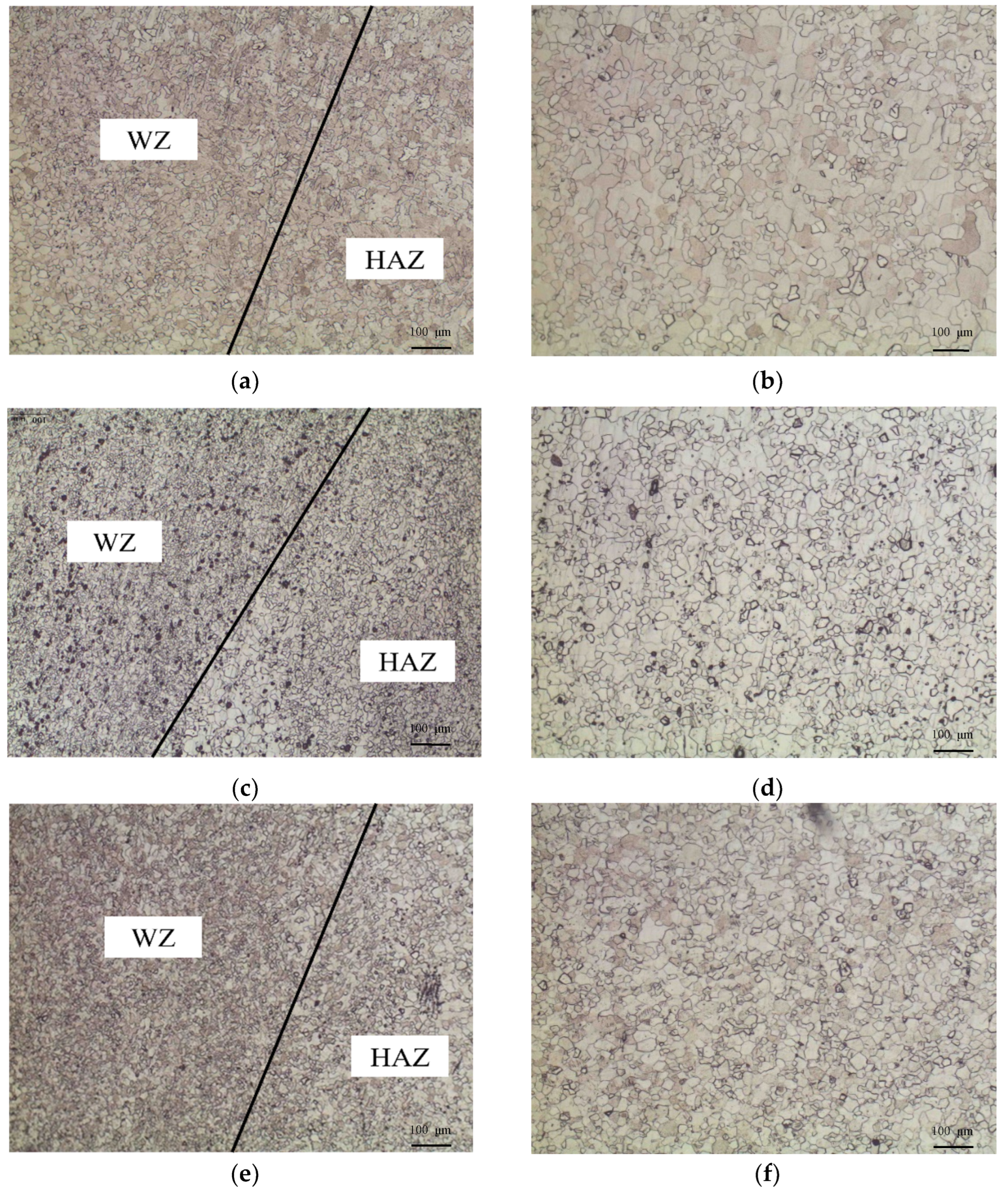
The third experiment: Only an X-shaped groove was used, and low-energy manual TIG arc welding with a lower welding current of 90 A was utilized. The number of welding passes was further decreased to 4, and the height of the weld bead remained consistent with that in the second experiment. Subsequently, the samples were processed through rolling passes of 6, 8, or 11 by a two-roll mill, and the total deformation of the weld seams was 45%, 55%, and 65%, while the deformation of the base metal was 21%, 35%, and 45%, respectively.
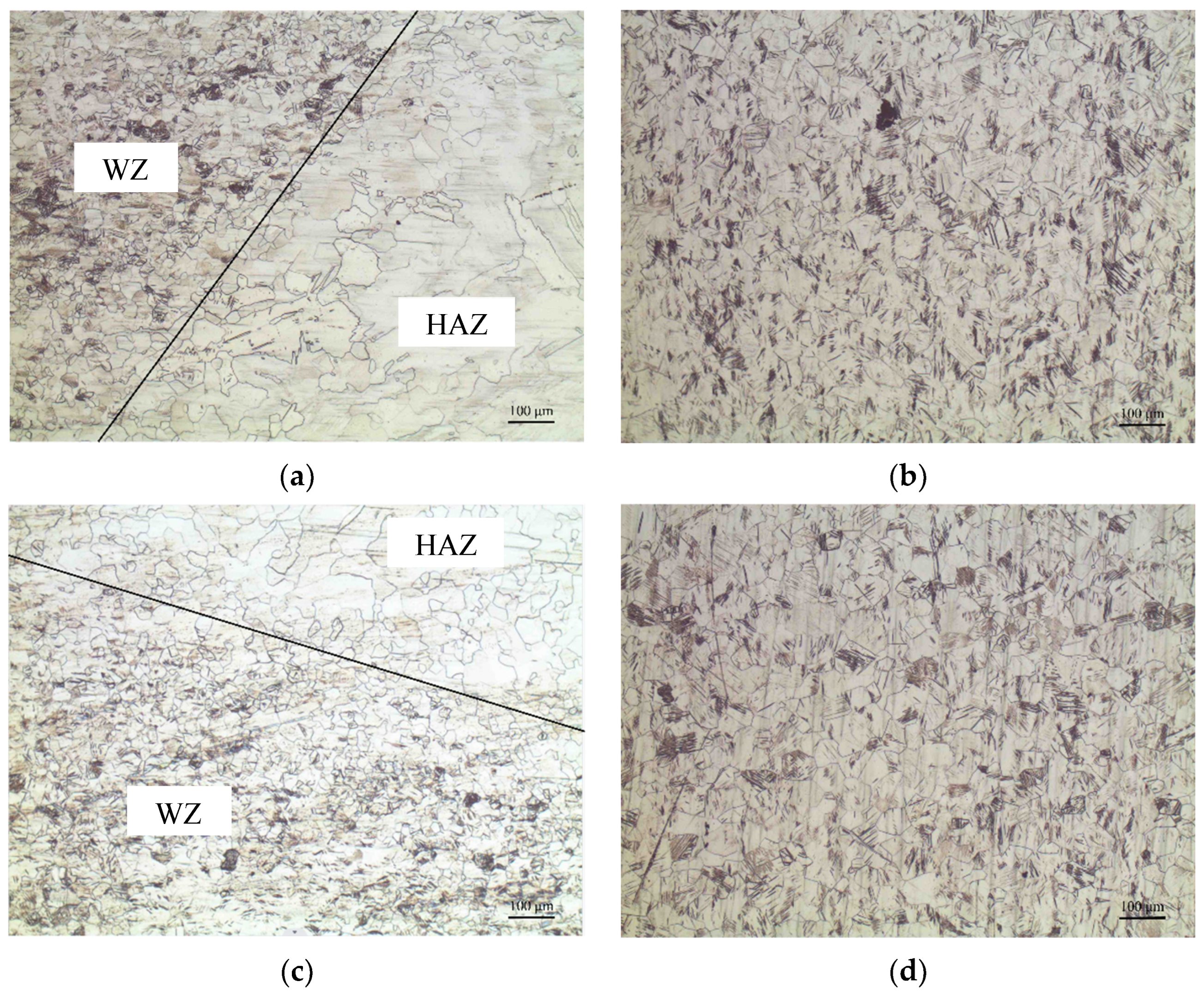
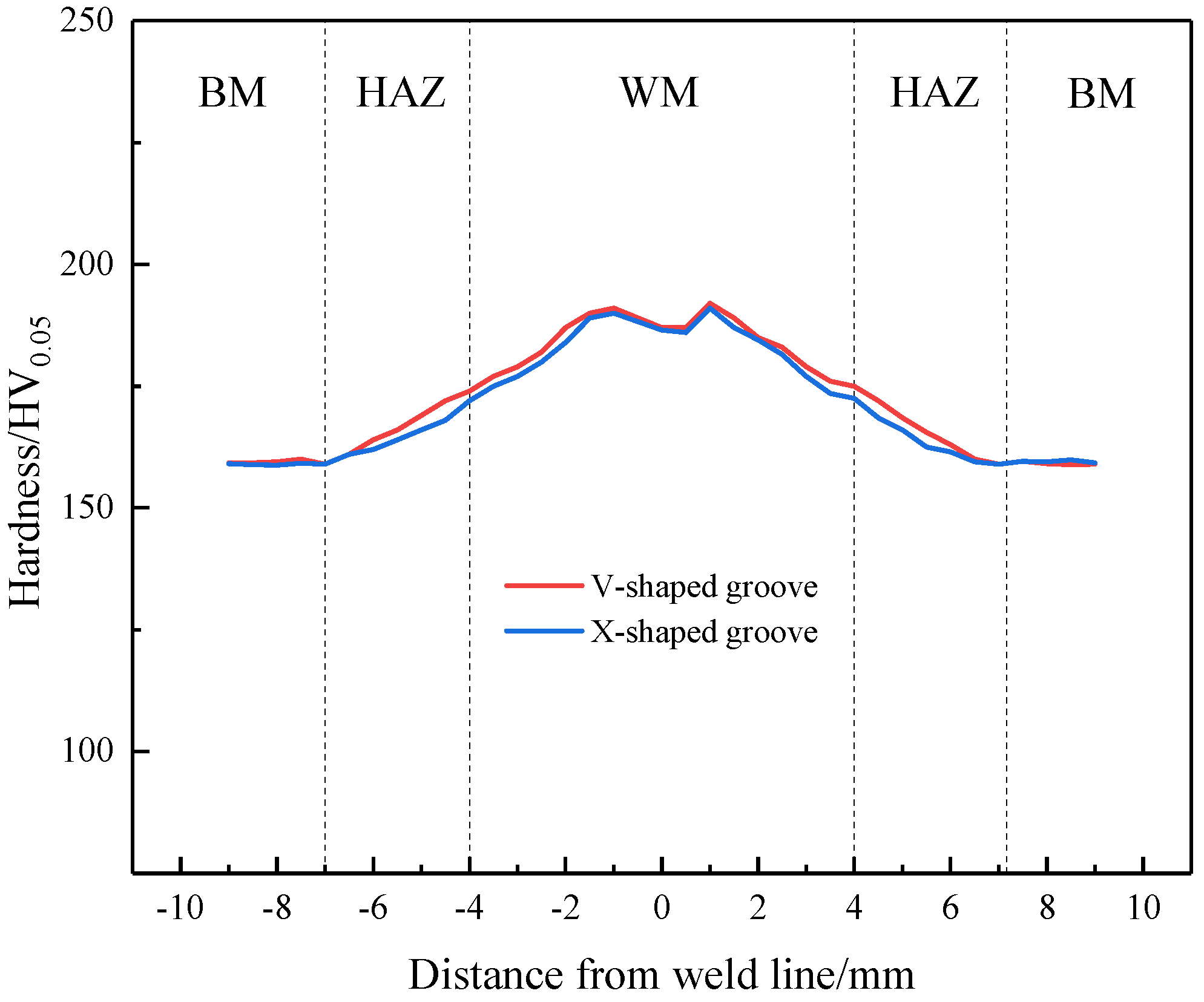
After the above three experiments involving various welding and deformation processes, all TA1 plates were annealed at 650 °C for a duration of 1 h in a BTF-1700C vacuum heat treatment furnace (Wuhan Fengshun Heat Treatment Technology Co., Ltd., Wuhan, China); then, wire cutting was employed to obtain samples from the junction between the weld area and the base metal of the TA1 plates. These samples were subsequently mounted on an XQ-2B metallographic sample mounting machine (Shanghai Shuyao Instrument Equipment Co., Ltd., Shanghai, China) at a temperature of 100 °C, with a holding time of 10 min. The mounted TA1 samples underwent sequential grinding using 80#, 400#, 800#, 1200#, and 2000# water sandpapers, followed by mechanical polishing on a YMP-2B metallographic sample grinding and polishing machine (Guangzhou Guru Tech Co., Ltd., Guangzhou, China). During the polishing process, a 50 nm alumina polishing solution was applied. Once the observed surfaces of the samples had achieved a scratch-free mirror finish, corrosion was performed using a solution composed of HF:HNO3:H2O in a ratio of 2:1:40. The microstructure of each area was observed using a DMI-3000M optical microscope (Shanghai Optical Instrument Factory, Shanghai, China), and the grain size was assessed via the intercept method. The Vickers hardness was measured using an HVS-30 Vickers hardness tester (Beijing Woway Technology Co., Ltd., Beijing, China).

3. Results

3.1. Results of First Experiment

3.1.1. Weld Morphology and Microstructure

Titanium plates with an original thickness of 8 mm and with V-shaped and X-shaped grooves underwent 12 passes of manual tungsten inert gas arc welding. A maximum thickness of 16 mm in the weld zone was obtained, and the height of the weld bead and the maximum thickness of the weld zone are summarized in Table 5, while the weld morphology is presented in Figure 2. The welds with both V-type and X-type grooves exhibited intact and defect-free welding surfaces.
Subsequently, the welded plates were subjected to a single cold pressing step using a 1600 T fast forging machine. The thickness of the weld seam was reduced to 8 mm, whereas the thickness of the base metal remained unchanged, i.e., the base metal did not experience deformation. Thus, as calculated via the following Formula (1), the deformation rates of the weld seam and the base metal were 50% and 0%, respectively.
ε = h 0 h f h 0 = Δ h h 0
where ∆h is the thickness change after rolling, mm; h0 is the original thickness prior to rolling, mm; hf is the thickness after rolling, mm; and ε is the deformation ratio.
The weld morphology after severe cold pressing is depicted in Figure 3. Evident cracking (as marked by red circles) occurred at both sides of the weld seam, although no defects were observed at the interface between the weld seam and the base metal.
After severe pressing, all specimens were vacuum-annealed at 650 °C for 1 h. The microstructure of each region, including the interface between the weld zone (WZ) and the heat-affected zone (HAZ), as well as the base metal, is shown in Figure 4. It can be observed that the microstructures of the two types of groove welds exhibited little difference; a seriously uneven grain size appeared in both cases, with the majority being coarse grains and a few fine recrystallized equiaxed grains in the HAZ. The results of the grain size grade measurements are presented in Table 6. The grain size grade in the WZ for both types of groove welds was within the range of 7~10, while the matrix grain size was graded as 7~8. There were slight differences in the HAZs of the two groove types: the grain size grade of the weld with the V-shaped groove in the HAZ was in the range of 3.5~10, whereas the grain size grade of the weld with the X-shaped groove was in the range of 4~10. It can be seen the majority of the grains in the HAZs of both grooves were coarse, although there existed a small number of fine equiaxed grains. By comparison, the grains in the HAZ of the X-shaped groove weld were finer than those in the X-shaped groove weld. Moreover, there was significant variation in the grain size across different regions of the welded plates, particularly in the HAZ, and the range of grain size grades was very wide.
From the above experimental results, it can be concluded that severe cold pressing followed by vacuum annealing not only failed to bring about the expected refining effect on the grains within the HAZ but also caused the serious side effect of cracking. Therefore, the method used in the first experiment cannot be promoted in engineering applications.
Considering all factors observed in the first experiment, this side effect could be attributed to the excessive number of welding passes and single-pass severe cold deformation; thus, fewer welding passes and multi-pass rolling deformation were adopted in the second experiment.

3.1.2. Microhardness

Figure 5 shows the microhardness profile of the welded titanium plate after severe cold pressing followed by annealing at 650 °C for 1 h. The hardness value of the base material is the lowest, followed by slightly higher hardness in the heat-affected zone, and the highest hardness value is located in the weld zone. Overall, the titanium plate with an X-shaped groove exhibits slightly lower hardness compared to that with a V-shaped groove. Notably, the hardness of the HAZ in the X-shaped groove case is quite similar, and the maximum microhardness values of the welded titanium plates with V-shaped and X-shaped grooves are 192 HV0.05 and 189 HV0.05, respectively—much higher than the value of 159HV0.05 for the matrix hardness.

3.2. Results of Second Experiment

3.2.1. Weld Morphology and Microstructure Observation

Manual tungsten inert gas (TIG) arc welding was performed on V-type and X-type groove titanium plates. The welding parameters were kept the same as those used in the first experiment, while the number of welding passes was decreased from 12 to 5. The height of the weld bead and the maximum thickness of the weld zone are illustrated in Table 7. The maximum thickness of the weld zone was 11.5 mm, while the thickness of the base material was 8 mm. Multi-pass rolling was followed by welding. The morphologies of the weld seams after multi-pass rolling are shown in Figure 6. It can be observed that there were no cracks at both ends of the weld seam, as marked by red circles. The thickness changes and deformation ratios in different areas after multi-pass rolling are summarized in Table 8. The thickness of the welded plate was reduced to 6.3 mm after multi-pass rolling, and the deformation rate was 45% and 21% for the weld seam and base material, respectively.
Subsequently, annealing at 650 °C for 1 h was conducted after rolling; the microstructures of different regions are depicted in Figure 7.
It is evident from Figure 7 that the grain sizes of the welding zone (WZ) and heat-affected zone (HAZ) in both groove specimens were significantly refined compared to those subjected to single-pass cold rolling in the first experiment. The matrix structure exhibited minimal changes. The grain size grade measurement results are summarized in Table 9.
It is evident that reducing the number of welding passes while increasing the number of deformation passes and the deformation ratio can result in the significant refinement of the weld zone and base material’s grains in both V-shaped and X-shaped groove samples. The grain size of the base material is uniform, with the grain size grade falling within the range of 7.5 to 8, while the grain size grade in the weld zone ranges between 7.5 and 10. Additionally, a notable grain size difference exists in the heat-affected zone (HAZ) between the V-shaped and X-shaped grooves. The grain size grades in the HAZ of the X-shaped groove sample are approximately 5.5 to 10, exhibiting a relatively uniform distribution. In contrast, the HAZ grains of the welded titanium plate with a V-shaped groove are coarser, with grain size grades ranging from 5 to 10.
Therefore, while reducing the number of welding passes and increasing the number of deformation passes and the deformation ratio resulted in a certain degree of grain refinement in various regions of the welded titanium plate, this effect was not significant and did not achieve the desired goal. The grain refinement effect in the HAZ of the welded titanium plate with an X-shaped groove was superior to that in the case of a V-shaped groove. Based on these findings, subsequent research will employ the X-shaped groove for welding. This superior result can be attributed to the high welding capacity, leading to differences in the grain structure.
The microstructure in the welding zone and the matrices of both types of groove specimens exhibited significant refinement. Additionally, it was observed that X-type groove welding was more effective in refining the grains within the heat-affected zone compared to V-type groove welding, resulting in a notable improvement in grain size uniformity.
The microstructures of various regions of the titanium plate weld are shown in Figure 8. In the center of the weld, fine equiaxed grains are observed, with a grain size grade ranging from approximately 8 to 9.5. In the upper portion of the weld, coarser grains are present, with size grades ranging from approximately 7.5 to 8.5. Additionally, cracks are evident in this region. The microstructure at different depths within the weld exhibits refinement and uniformity. Compared to the first experiment, there is a notable improvement in microstructure refinement and homogeneity, thereby facilitating further advancement.
From the results of the second experiment, it can be concluded that reducing the number of welding passes and increasing the number of deformation passes and the deformation ratio can not only bring about obvious grain refinement in various regions of the welded titanium plate but also avoid the cracking that occurred in the first experiment. Although the grain refinement effect obtained in the second experiment did not meet the technical requirements, it provides a direction for further research. Therefore, fewer welding passes with a lower welding current, more rolling passes, and a higher deformation ratio were explored in the third experiment.

3.2.2. Microhardness

The microhardness profiles of the welded titanium plates with X- and V-shaped grooves, subjected to eight welding passes, multi-pass rolling, and vacuum annealing at 650 °C for 1 h, are presented in Figure 9. A comparison of the microhardness across different regions of the welded plates from Experiments 1 and 2 reveals that both experiments exhibited similar trends in hardness variation. However, the main difference lies in the reduction in hardness in the weld zone for Experiment 2, accompanied by an increase in hardness in the HAZ and the base material. Specifically, the hardness values in the weld zone and HAZ of the X-shaped groove are slightly lower than those in the case of the V-shaped groove. The maximum hardness in the weld zone decreased to approximately 187 HV0.05, while the base material’s hardness increased to around 164 HV0.05. Overall, it can be concluded that, as the number of welding passes is reduced and the number of rolling passes and the deformation rate are increased, the differences in hardness among various regions of the welded plates become less pronounced.

3.3. Results of Third Experiment

3.3.1. Microstructure Observation

Low-energy welding was performed on the titanium plates with the welding current reduced to 90 A. After four passes, the weld bead height reached 11.5 mm. The height of the weld bead and the thickness of the weld zone and plate are illustrated in Table 10. Three X-shaped groove specimens underwent multi-pass rolling after welding, and the thickness of the deformed plate was 6.3, 5.2, and 4.0, respectively, corresponding to the deformation ratios of 45%, 55%, and 65% for the weld seam and the deformation ratios of 21%, 35%, and 45% for the base metal, respectively. The thickness changes and deformation ratios in different areas after multi-pass rolling are summarized in Table 11.
The microstructures of various regions in the third experiment after annealing are shown in Figure 10. The welded areas exhibited a recrystallized equiaxed structure for all samples with deformation ratios of 45%, 55%, and 65%. After employing low-energy welding, the microstructure differences between the heat-affected zone (HAZ) and the base material became indistinguishable under varying ratios of rolling deformation. As the deformation ratio increases, the grains in each region of the welded plate are gradually refined.
The grain size grades of each region in the X-type groove welded specimens subjected to different deformation ratios are presented in Table 12. The grain size grades in each region were progressively refined with the increase in the rolling deformation ratio. When the weld deformation ratio reached 65%, the grain size in the weld zone was graded 9–10, while the grain size grade in the heat-affected zone aligned with that of the base material, ranging from 8.5 to 9.
Finally, the experimental results demonstrate that, after the low-energy welding of titanium plates, followed by multi-pass rolling and subsequent annealing heat treatment, the microstructure of the weld zone can be effectively refined. The deformation of the weld during rolling reaches approximately 45%. After annealing at 650 °C for one hour, the grains in all regions of the weld are significantly refined, achieving a uniform grain size. There is no discernible difference between the weld zone and the matrix structure, with both exhibiting refined grains.
Therefore, low-energy welding with four passes and multi-pass rolling deformation with a ratio of 45% is the most suitable process for practical production applications.

3.3.2. Microhardness Analysis

Figure 11 shows the microhardness profiles across the weld seam in low-energy-welded titanium plates with X- and V-shaped grooves, subjected to multi-pass rolling until the weld bead deformation ratio reached 45%, 55%, and 65%, followed by vacuum annealing at 650 °C for 1 h. It is evident that, compared with Process 1 and Process 2, the microhardness profile remained consistent across all regions of the low-energy-welded plates. While the hardness of the weld zone decreased, the hardness of the heat-affected zone and the matrix increased. As the deformation ratio increased, the overall hardness difference among the welded plate regions was gradually diminished. When the weld bead deformation rate reached 45%, the maximum hardness of the weld zone dropped to 183 HV0.05, whereas the matrix hardness rose to 170 HV0.05, resulting in a minimum hardness difference of 11 HV0.05.

4. Analysis

By systematically analyzing the results of the three experiments conducted under different conditions, a comparative evaluation of the grain size refinement effects across different regions of the titanium plate can be achieved, as presented in Table 13.
In comparison with the V-type groove, the X-type groove welding technique involves reduced metal deposition, thereby decreasing the required heat input for welding. Heat is transferred and dispersed between the two V-type grooves, leading to more uniform heat distribution. Consequently, the X-type groove is more effective in refining the microstructure of the heat-affected zone.
As for the selection of the number of welding passes, when the weld seam is subjected to excessive welding passes, corresponding to multiple heating and cooling cycles, it results in increased heat input. Each thermal cycle promotes grain growth within the heat-affected zone (HAZ), and repeated heating can lead to more complex microstructural changes, such as the formation of coarser grains. Consequently, reducing the number of welding passes to a suitable value can facilitate the attainment of finer grains.
Lowering the welding current typically reduces the energy input, thereby decreasing the generated heat and mitigating the risk of grain coarsening due to elevated temperatures. Therefore, when the welding current is reduced to a low energy level of 90 A, the microstructure in all regions of the weld seam exhibits finer grains.
Based on the results, it can also be concluded that increasing both the number of rolling passes and the degree of rolling deformation can effectively refine the microstructure in various regions of the welded plate. This refinement mechanism primarily results from the generation of high-density dislocations within α-Ti grains during rolling deformation, which form a sub-grain boundary network. The strain energy accumulated during cold rolling subsequently provides an enhanced driving force for recrystallization [22].

5. Conclusions

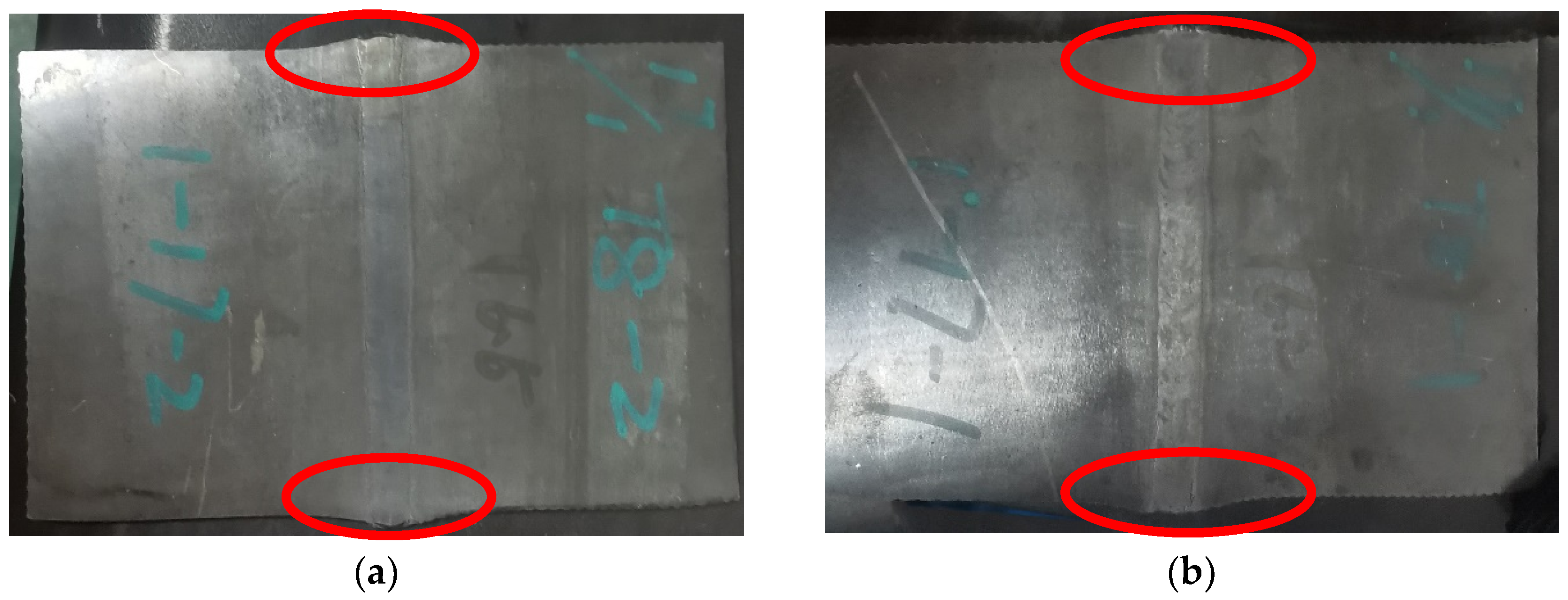
A novel composite technology consisting of low-energy and fewer-pass welding combined with multi-pass rolling deformation and vacuum annealing treatment was developed for high-purity TA1 titanium plates used for cathode rolls, and its comprehensive effects on the microstructure and hardness of the weld zone and heat-affected zone (HAZ) was investigated in this study. The research results show that, after multi-pass welding followed by single-pass severe cold rolling, weld cracking occurs. By employing X-type grooves, reducing the number of welding passes, and subsequently applying multi-pass rolling deformation treatment, weld cracking is effectively prevented. After annealing heat treatment, the grain size in all regions is significantly refined compared to single-pass severe cold pressing, which facilitates the refinement of the microstructure in both the weld zone and HAZ, thus improving the grain uniformity and reducing the microhardness variations across the welded plate, indicating that the X-type groove welding method is more effective for grain refinement. Under low-energy welding conditions with a current of 90 A, the number of welding passes can be further reduced to four while maintaining a consistent weld height, thereby avoiding coarse grains in the HAZ caused by excessive heat from multiple passes. Additionally, after 45% multi-pass weld rolling and annealing heat treatment, the grains in the HAZ are significantly refined and indistinguishable from those of the base metal, with the overall microhardness variation minimized. Through the systematic exploration of this manufacturing technology, it is found that low-energy welding with four welding passes, followed by multiple passes of rolling with a deformation ratio of 45% and, finally, annealing at 650 °C for 1 h, is the optimal process to refine the grain size and improve the properties of welded TA1 titanium plates for cathode rollers. Therefore, this research provides a robust technical foundation for the advancement of the “welding” process of titanium cylinder sleeves for cathode roll surfaces.

Author Contributions

L.Q.: Conceptualization, methodology, writing—original draft, data curation. J.H.: Supervision, writing—review and editing. D.W.: Project administration. J.G.: Visualization. W.J.: Software, validation. X.A.: Investigation. W.W.: Investigation. All authors have read and agreed to the published version of the manuscript.

Funding

This research was supported by the National Natural Science Foundation of China (21978025), the Natural Science Foundation for Young Scholars of Jiangsu Province (BK20220628), the National Natural Science Foundation for Young Scholars of China (52301130), the Priority Academic Program Development of Jiangsu Higher Education Institutions (PAPD-3), and the Top-Notch Academic Program Projects of Jiangsu Higher Education Institutions (TAPP).

Institutional Review Board Statement

Not applicable.

Informed Consent Statement

Not applicable.

Data Availability Statement

The data that support the findings of this study are available from the corresponding author.

Acknowledgments

The authors thank the National Natural Science Foundation of China (No. 21978025), Changzhou Science and Technology Bureau (No. CJ20245044), Changzhou Health Commission (No. ZD202441), and Postgraduate Research & Practice Innovation Program of Jiangsu Province (SJCX25_1712) and acknowledge the strong support of their cooperation partner, Changzhou China Steel Precision Materials Co., Ltd.

Conflicts of Interest

Author Dayue Wang was employed by the company Changzhou Sinosteel Precision Forging Materials Co., Ltd. The remaining authors declare that the research was conducted in the absence of any commercial or financial relationships that could be construed as a potential conflict of interest.

References

  1. Song, Y.X.; Lu, W.Y.; Chen, Y.J.; Yang, H.; Wu, C.; Wei, W.F.; Chen, L.B.; Ouyang, X.P. Coating highly lipophilic Zn on Cu foil for high-performance lithium metal batteries. Rare Met. 2022, 41, 1255–1264. [Google Scholar] [CrossRef]
  2. Zhou, B.X.; Bonakdarpour, A.; Stoševski, I.; Fang, B.; Wilkinson, D.P. Modification of Cu current collectors for lithium metal batteries—A review. Prog. Mater. Sci. 2022, 130, 100996. [Google Scholar] [CrossRef]
  3. Jang, S.; Jeong, H.; Yuh, M.; Park, J. Effect of surfactant on package substrate in chemical mechanical planarization. Int. J. Precis. Eng. Manuf. Green. Technol. 2015, 2, 59–63. [Google Scholar] [CrossRef]
  4. Hao, R.J.; Zhao, Y.X.; Su, J.H.; Yang, J.; Tan, C.W.; Song, X.G. Bonding mechanism of laser joining of Poly-Ether-Ether-Ketone film which used for 5G antenna substrate to copper foil. J. Manuf. Process. 2023, 108, 153–164. [Google Scholar] [CrossRef]
  5. Dong, Z.C.; Fei, X.Y.; Feng, L.; Nie, J.W.; Li, W.J.; Gong, B.K. Effects of deformation and applied temperature on the microstructure and performance of industrial ultra-thin rolled Cu foil. J. Mater. Res. Technol. 2023, 23, 4268–4279. [Google Scholar] [CrossRef]
  6. Yu, H.L.; Zhao, X.S.; Kong, C. Mechanical properties of rolled copper foils in cryogenic and room-temperature environments. Adv. Eng. Mater. 2022, 24, 2100830. [Google Scholar] [CrossRef]
  7. Hung, Y.W.; Tran, D.P.; Chen, C. Effect of Cu ion concentration on microstructures and mechanical properties of nanotwinned Cu foils fabricated by rotary electroplating. Nanomaterials 2021, 11, 2135. [Google Scholar] [CrossRef]
  8. Popov, K.I.; Nikoli, N.D.; Zivkovi, P.M.; Brankovic, G. The effect of the electrode surface roughness at low level of coarseness on the polarization characteristics of electrochemical processes. Electrochim. Acta 2010, 55, 1911925. [Google Scholar] [CrossRef]
  9. Sun, J.; Liu, N.; Xia, L.; Wu, D. Research of oil film thickness model and surface quality in cold rolling copper foil. Lubr. Sci. 2013, 26, 95–106. [Google Scholar] [CrossRef]
  10. Lu, L.L.; Liu, H.T.; Wang, Z.D.; Lu, Q.Q.; Zhou, Y.J.; Zhou, F.; Zhang, Y.M.; Lu, W.W.; Yang, B.; Zhu, Q.Q.; et al. Advances in electrolytic copper foils: Fabrication, microstructure, and mechanical properties. Rare Met. 2024, 44, 757–792. [Google Scholar] [CrossRef]
  11. Lee, C.Y.; Moon, W.C.; Jung, S.B. Surface finishes of rolled copper foil for flexible printed circuit board. Mater. Sci. Eng. A 2008, 483, 723–726. [Google Scholar] [CrossRef]
  12. Xia, L.; Li, Y.; Zhao, S.; Xiong, S.; Jiang, Z.Y. Corrosion Characteristics of Rolling Oil on the Rolled Copper Foil. Materials 2020, 13, 4933. [Google Scholar] [CrossRef] [PubMed]
  13. Ahmadikia, B.; Wang, L.; Kumar, M.A.; Beyerlein, I.J. Grain boundary slip—Twin transmission in titanium. Acta Mater. 2023, 244, 118556. [Google Scholar] [CrossRef]
  14. Bendikiene, R.; Baskutis, S.; Baskutiene, J.; Ciuplys, A.; Kacinskas, T. Comparative study of TIG welded commercially pure titanium. J. Manuf. Process. 2018, 36, 155–163. [Google Scholar] [CrossRef]
  15. Chong, Y.; Gholizadeh, R.; Tsuru, T.; Zhang, R.P.; Inoue, K.; Gao, W.Q.; Godfrey, A.; Mitsuhara, M.; Morris, J.W.; Minor, A.M. Grain refinement in titanium prevents low temperature oxygen embrittlement. Nat. Commun. 2023, 14, 404. [Google Scholar] [CrossRef]
  16. Hu, Y.Y.; Li, J.L.; Yang, W.Q.; Ma, X.F.; Liu, H.J.; Wang, B.A. Role of ultrasonic in synergistic strengthening of friction stir welded alloys by grain refinement and rapid nanoscale precipitation. Mater. Sci. Eng. A-Struct. 2022, 838, 142751. [Google Scholar] [CrossRef]
  17. Sun, X.T.; Lin, H.S.; Chen, X.S.; Zhang, P. Comparative study on electrocrystallization of calcium phosphate ceramics on commercially pure titanium and selective laser melting titanium. Mater. Lett. 2017, 192, 92–95. [Google Scholar] [CrossRef]
  18. Oh, W.B.; Kim, I.S.; Yun, T.J.; Lee, B.R.; Lee, C.W.; Yong, K.B.; Shim, J.Y. A Study on the Optimization of Welding Conditions for Titanium Drums Using GPS. J. Weld. Join. 2021, 39, 419–426. [Google Scholar] [CrossRef]
  19. Wu, J.W.; Wang, Z.M.; Lin, S.B.; Xie, Z.C.; Xu, M.G.; Tian, J.Y.; Guo, C.F. Effect of fast-frequency pulsed waveforms on the microstructure and mechanical properties of Ti-6Al-4V alloy welded by FFP-TIG. J. Mater. Res. Technol. 2022, 20, 516–531. [Google Scholar] [CrossRef]
  20. Hou, Z.G.; Liu, H.T.; Li, W.Q.; Chen, C.; Zhang, Z.H.; Dong, J.C.; Lu, W.W.; Feng, Q.; Jia, B.; Song, K.X. Effect of trace Sc on corrosion behavior of titanium material in cathode roller for electrolytic copper foil. Corros. Sci. 2025, 246, 112722. [Google Scholar] [CrossRef]
  21. Xu, Y.; Wang, D.; Li, M.; Hu, J.; An, X.; Wei, W. The Effect of Novel Complex Treatment of Annealing and Sandblasting on the Microstructure and Performance of Welded TA1 Titanium Plate. Materials 2023, 6, 2149. [Google Scholar] [CrossRef]
  22. Tse, Y.Y.; Liu, G.L.; Duggan, B.J. Deformation banding and nucleation of recrystallisation in if steel. Scr. Mater. 1999, 42, 25–30. [Google Scholar] [CrossRef]
Figure 1. Morphologies of V-shaped and X-shaped welding grooves. (a) V-shaped groove; (b) X-shaped groove.
Coatings 15 00687 g001
Figure 2. Weld morphologies of V-type and X-type grooves: (a) V type; (b) X type.
Coatings 15 00687 g002
Figure 3. Weld morphologies of V-type and X-type grooves after severe pressing. (a) V-type groove; (b) X-type groove.
Coatings 15 00687 g003
Figure 4. Microstructures of V-shaped and X-shaped welded titanium plates in different regions after annealing at 650 °C for 1 h. (a) Interface between weld zone and heat-affected zone of V-shaped groove; (b) matrix of V-shaped groove; (c) interface between weld zone and heat-affected zone of X-shaped groove; (d) matrix of X-shaped groove.
Coatings 15 00687 g004
Figure 5. Microhardness of each area of a titanium plate obtained in the first experiment after annealing.
Coatings 15 00687 g005
Figure 6. Weld morphologies of V-type and X-type grooves after multi-pass rolling. (a) V-type groove; (b) X-type groove.
Coatings 15 00687 g006
Figure 7. Microstructures of each area of welded titanium plates with different grooves after being pressed down and annealed at 650 °C for 1 h. (a) Weld and heat-affected zone of V-shaped groove; (b) base metal of V-shaped groove; (c) weld and heat-affected zone of X-shaped groove; (d) base metal of X-shaped groove.
Coatings 15 00687 g007
Figure 8. Microstructures of each area of the V-shaped titanium plate weld. (a) Center of surface welding; (b) upper part of surface welding.
Coatings 15 00687 g008
Figure 9. Microhardness of each area of a titanium plate obtained in the second experiment after annealing.
Coatings 15 00687 g009
Figure 10. Microstructures of each area of welded titanium plates with different deformation ratios after annealing at 650 °C for 1 h. (a) Weld and heat-affected zone with 45% weld deformation ratio; (b) base metal with 21% base deformation ratio; (c) weld and heat-affected zone with 55% weld deformation ratio; (d) base metal with 35% base deformation ratio; (e) weld and heat-affected zone with 65% weld deformation ratio; (f) base metal with base deformation ratio of 45%.
Coatings 15 00687 g010
Figure 11. Microhardness of each area of a titanium plate obtained in the third experiment after annealing.
Coatings 15 00687 g011
Table 1. Chemical composition of TA1 titanium plate (wt. %).
ElementCHNOFeTi
Content0.0070.00060.00150.0320.029Balance
Table 2. Mechanical properties of TA1 titanium plate.
Tensile Strength/MPaYield Strength/MPaElongation/%
253161.563.1
Table 3. Dimensions of the two types of welding grooves.
Groove TypeGroove Dimensions
Groove Clearance/mmGroove Angle/(°)
X170
V174
Table 4. Welding parameters of manual tungsten pole argon arc welding.
Welding Current, AWelding Voltage, VWelding Speed, cm·min−1
1158~95.3
Table 5. Height of weld bead and maximum thickness of weld zone after welding.
Groove TypeWelding Pass, TimesHeight of Weld Bead, mmMaximum Thickness of Weld Zone, mmThickness of Plate, mm
V128168
X4 on each side16
Table 6. Grain size grades and equivalent diameters in different areas of welded specimens with different grooves.
Groove TypeGrain Size Grades and Equivalent Diameters in Different Areas of Welded Specimens
Weld Zone (WZ)Heat-Affected Zone (HAZ)Matrix
V7~10 (20.1 μm)3.5~10 (55.4 μm)7~10 (29.7 μm)
X7~10 (21.3 μm)4~10 (49.8 μm)7~10 (29.5 μm)
Table 7. Height of weld bead and maximum thickness of weld zone after welding.
Groove TypeWelding Pass, TimesHeight of Weld Bead, mmMaximum Thickness of Weld Zone, mmThickness of Plate, mm
V53.511.58
X1.75 on each side
Table 8. Thickness changes and deformation ratios in different areas after rolling.
Groove TypeThickness Prior to Deformation, mmThickness of Deformed Plate, mmDeformation Ratio,%
Weld SeamBase MetalWeld SeamBase Metal
V11.586.345%21%
X
Table 9. Grain size grades and equivalent diameters in different areas of welded specimens with different grooves.
Groove TypeGrain Size Grades and Equivalent Diameters in Different Areas of Welded Specimens
Weld ZoneHeat-Affected ZoneMatrix
V7.5~10 (17.1 μm)5~10 (39.3 μm)8.5~10 (18.6 μm)
X7.5~10 (17.2 μm)5.5~10 (35.1 μm)8.5~10 (18.7 μm)
Table 10. The height of the weld bead and thickness of the weld zone and plate after welding.
Groove TypeWelding Pass, TimesHeight of Weld Bead, mmTotal Thickness of Weld Zone, mmThickness of Plate, mm
X41.75 on each side11.58
Table 11. The thickness changes and deformation ratios in different areas after multi-pass rolling.
Groove TypeThickness Prior to Deformation, mmThickness of Deformed Plate, mmDeformation Ratio, %
Weld SeamBase MetalWeld SeamBase Metal
X11.586.34521
5.25535
4.06545
Table 12. Grain size grades and equivalent diameters in different areas of welded specimens with different grooves.
Groove TypeDeformation Ratio, %Grain Size Grades and Equivalent Diameters in Different Areas of Welded Specimens
WeldBase MetalWeld ZoneHeat-Affected ZoneMatrix
X45207.5~10 (20.1 μm)7.5~10 (21.4 μm)7.5~10 (21.5 μm)
55358.5~10 (15.3 μm)8~10 (19.8 μm)8~10 (19.5 μm)
65459~10 (13.3 μm)8.5~10 (16.8 μm)8.5~10 (16.1 μm)
Table 13. Comparative analysis of grain size refinement effects in various regions of titanium plates after three experiments under different conditions.
ExperimentGroove TypeDeformation Ratio of Weld Seam, %Grain Size Grade
WZHAZMatrix
1V507~103.5~107~10
X507~104~107~10
2V457.5~105~108.5~10
X457.5~105.5~108.5~10
3X457.5~107.5~107.5~10
558.5~108~108~10
659~108.5~108.5~10
Disclaimer/Publisher’s Note: The statements, opinions and data contained in all publications are solely those of the individual author(s) and contributor(s) and not of MDPI and/or the editor(s). MDPI and/or the editor(s) disclaim responsibility for any injury to people or property resulting from any ideas, methods, instructions or products referred to in the content.

