Article

Microstructural Evolution and Wear Resistance of Silicon-Containing FeNiCrAl0.7Cu0.3Six High-Entropy Alloys

1
School of Engineering, Jilin Business and Technology College, No. 1666, Kalunhu Street, Changchun 130507, China
2
School of Mechanical and Vehicle Engineering, West Anhui University, Yueliangdao Road, No. 1, Lu′an 237010, China
*
Author to whom correspondence should be addressed.
Coatings 2025, 15(6), 676; https://doi.org/10.3390/coatings15060676
Submission received: 30 March 2025 / Revised: 28 May 2025 / Accepted: 30 May 2025 / Published: 3 June 2025

Abstract

:
This study investigates the influence of Si content (x = 0, 0.1, 0.3, 0.5) on the microstructure, mechanical properties, and wear behavior of FeNiCrAl0.7Cu0.3Six high-entropy alloys. With increasing silicon content, the microstructure evolves from a dendritic morphology in the silicon-free FeNiCrAl0.7Cu0.3 alloy to a transitional structure in the FeNiCrAl0.7Cu0.3Si0.1 alloy that retains dendritic features; then to a chrysanthemum-like morphology in the FeNiCrAl0.7Cu0.3Si0.3 alloy, and finally to island-like grains in the FeNiCrAl0.7Cu0.3Si0.5 alloy. This evolution is accompanied by a phase transition from an Fe and Cr-rich body-centered cubic phase to an Al and Ni-rich body-centered cubic phase, with silicon showing a tendency to segregate alongside aluminum and nickel. The microhardness increases from 498.2 ± 15.0 HV for the FeNiCrAl0.7Cu0.3 alloy, to 502.7 ± 32.7 HV for FeNiCrAl0.7Cu0.3Si0.1, 577.3 ± 24.5 HV for FeNiCrAl0.7Cu0.3Si0.3, and 863.2 ± 23.5 HV for FeNiCrAl0.7Cu0.3Si0.5. The average friction coefficients are 0.571, 0.551, 0.524, and 0.468, respectively. The wear mass decreases from 1.31 mg in the FeNiCrAl0.7Cu0.3 alloy to 1.28 mg, 1.11 mg, and 0.78 mg in the FeNiCrAl0.7Cu0.3Si0.1, FeNiCrAl0.7Cu0.3Si0.3, and FeNiCrAl0.7Cu0.3Si0.5 samples, respectively. These trends are consistent with the increase in microhardness, supporting the inverse relationship between hardness and wear. As the silicon content increases, the dominant wear mechanism changes from abrasive wear to adhesive wear, with the high-silicon alloy exhibiting lamellar debris on the worn surface. These findings confirm that silicon addition enhances microstructural refinement, mechanical strength, and wear resistance of the alloy system.

1. Introduction

Alloys such as steel, copper alloys, magnesium alloys, titanium alloys, and aluminum alloys are widely employed in engineering, typically based on 1–2 principal metal elements with minor additions to enhance their performance. However, traditional alloys exhibit limitations under specialized and extreme conditions due to rapidly evolving industrial requirements. Consequently, developing new high-performance materials is critical. In 2004, Yeh J.W. and others [1,2] introduced the concept of high-entropy alloys (HEAs), showing that alloys with multiple principal elements in roughly equal proportions generally develop uncomplicated multi-component solid solutions during solidification [3,4], instead of intermetallic compounds. These alloys offer a combination of high strength [5,6,7,8], excellent toughness [9,10,11,12], superior high-temperature performance [13,14,15], strong corrosion resistance [16,17,18], and outstanding wear resistance [19,20], making them advantageous over conventional alloys. Their unique elemental composition and microstructural characteristics suggest potential in structural materials [21,22], thin films [23,24], and protective coatings [25,26].
Currently, studies on HEA systems mainly explore refractory HEAs [27,28], lightweight HEAs [29,30], and transition metal-based HEAs [31,32]. Among them, the Fe-Cr-Ni-Co-Al alloy family, classified as a transition metal system, has garnered the most attention. Its properties can be tailored by adjusting the principal element content [33,34], or by adding supplementary alloying components [35,36,37]. Yeh et al. [1,2] initially introduced the concept of HEAs, and subsequent research extensively explored Fe-Cr-Ni-Co-Al alloys. Kao et al. [38] found that augmenting the Al proportion in AlxCoCrFeNi (x = 0 to 2) transforms the microstructure from a flexible FCC configuration to a more robust and rigid BCC structure. The transformation sequence progresses from single-phase FCC (x = 0 to 0.45), through a dual-phase BCC and FCC structure (x = 0.45 to 0.88), and finally to single-phase BCC (x = 0.88 to 2.00). Yang et al. [39] investigated the tribocorrosion behavior of CoCrFeNi-based HEA coatings containing Ti, Mn, Mo, and Al in 3.5 wt% NaCl solution under reciprocating friction. The study revealed that friction increased the local corrosion rate by 2–3 orders of magnitude and accelerated material loss due to the synergistic effects of wear and corrosion. Wu et al. [40] studied the wear and corrosion behavior of AlCrFeCoNi and AlCrFeCoNiTi0.5 HEAs in NaCl and HCl solutions. They found that Ti addition enhanced hardness and improved pitting corrosion resistance by promoting the formation of a more protective passive film. Chin-You Hsu et al. [41] observed that substituting Fe in AlCoCrFexMo0.5Ni alloys (x = 0.6–2) significantly influenced their hardness and wear properties. Alloys with lower Fe content exhibited dendritic structures and higher hardness compared to higher Fe content alloys, which displayed increased oxidation and wear at elevated temperatures.
Incorporating non-metallic elements like N, C, B, and Si allows for the fine-tuning of HEAs’ properties. Song et al. [42] found that nitrogen addition enhanced the strength and ductility of FeCoCrNi HEAs by approximately 25%. Lei et al. [43] demonstrated that nitrogen addition significantly refined the grain size in FeCoCrNiMn HEAs from 7.6 μm to 2.5 μm. Additionally, Xiong et al. [44] reported that nitrogen doping changed deformation mechanisms from twinning to deformation-induced microbands, thus enhancing mechanical performance. Zhu et al. [45] showed that carbon addition led to carbide formation and graphite segregation in AlCoCrFeNi alloys, significantly increasing yield stress and decreasing Young’s modulus at higher carbon contents while reducing grain size and improving compressive strength and fracture strain. Zhu et al. [45] found that silicon addition created nanoscale cellular structures within AlCoCrFeNi alloys, enhancing mechanical strength through solid solution strengthening and nanoscale precipitates. Guo et al. [46] observed that silicon significantly improved thermal stability and strength through phase transformations, producing BCC, B2, and sigma phases, although altering fracture behavior from ductile to brittle.
To reduce the compositional complexity and cost of Fe-Cr-Ni-Co-Al HEAs, we designed the FeCrNiAl0.7Cu0.3Six HEA system based on previous research on the Fe-Cr-Ni-Co-Al alloy [47,48,49] by removing the Co element. Our corrosion resistance studies [50] demonstrated that Si significantly improved corrosion resistance, with optimal performance at a Si content of 0.3. However, excessive Si (0.5) led to the formation of Cr5Si3 phases, which reduced corrosion resistance. Given that the mechanical and chemical properties of materials are often interrelated, wear resistance—an important parameter for applications in aerospace, deep-sea, and extreme-temperature environments—also warrants investigation. Therefore, the purpose of this study is to systematically explore the effect of Si content on the microstructure, microhardness, and wear behavior of FeCrNiAl0.7Cu0.3Six high-entropy alloys, aiming to reveal the underlying wear mechanisms and evaluate their suitability for practical engineering applications.

2. Materials and Methods

HEAs were fabricated using an MTDH-600 non-consumable high-vacuum arc melting furnace (Shenyang Kejing, Shenyang, China). Pre-weighed metal raw materials were loaded into a copper crucible within the furnace, arranging low-melting-point and volatile materials at the bottom and high-melting-point and less volatile materials on top. The furnace was evacuated slowly until achieving a vacuum level below 6.0 × 10⁻³ Pa, followed by filling with high-purity argon gas up to 0.5 atm. Initially, a tungsten electrode created an arc to melt a titanium ingot, eliminating residual oxygen. Subsequently, the prepared metals were melted under the arc. After achieving full melting, electromagnetic stirring was conducted, followed by repeatedly flipping and re-melting each alloy ingot no fewer than four times to achieve uniform composition. The final ingots had a button-like shape.
Compared to methods like laser cladding [51], mechanical alloying [52], and spark plasma sintering [53], arc melting is a simpler and more cost-effective way for preparing bulk high-entropy alloys. While laser cladding is good for surface coatings with fine structures, it often causes composition segregation. Arc melting, on the other hand, allows repeated melting and better composition control, making it more suitable for studying alloy design and bulk properties.
FeNiCrAl0.7Cu0.3Six alloys were designed. Among them, Fe, Ni, and Cr were selected as the principal elements due to their similar atomic radii and high mutual solubility, which are favorable for forming solid solution phases in high-entropy alloys. Al was introduced to enhance the strength of the alloy [54], while Cu was added as an FCC phase-forming element to improve ductility [55]. Si was varied systematically to study its effect on the microstructure and wear resistance of the alloy. The nominal compositions and sample abbreviations of the FeNiCrAl0.7Cu0.3Six HEAs are summarized in Table 1.
Before microstructural observation, all alloy ingots were sectioned using a precision low-speed diamond saw to obtain cross-sectional samples. These samples were mounted in epoxy resin and successively ground with SiC abrasive papers from 240 to 2000 grit, followed by polishing with 1 μm diamond suspension on a polishing cloth until a mirror-like surface was obtained. The polished samples were then ultrasonically cleaned in ethanol for 10 min and air-dried. For microstructural analysis by SEM, the cleaned samples were etched using freshly prepared aqua regia (HCl:HNO3 = 3:1 by volume) for 30 s to reveal the grain boundaries and phase distribution.
Microstructural analysis was performed using a Quanta 250 FEG field emission scanning electron microscope (Thermo Fisher Scientific, Waltham, MA, USA). Prior to observation, specimens were etched with aqua regia to reveal microstructural features. Secondary electron (SE) imaging was used to observe surface morphology and contrast, and energy-dispersive spectroscopy (EDS) was applied to determine elemental distribution.
For microhardness testing, the samples were coarsely ground to ensure a flat and even surface. Microhardness tests were conducted using an HSV-1000A digital micro Vickers hardness tester (Shanghai Taiming Optical Instrument Co., Ltd., Shanghai, China). For each sample, six measurements were taken at different locations, and the average value and standard deviation were calculated.
Wear performance was evaluated using an MM-10000A reciprocating wear tester (Jinan Zhongbiao Instrument Co., Ltd., Jinan, China) in a ball-on-flat configuration under dry sliding conditions. The counterbody was a tungsten carbide (WC) ball with a diameter of 6 mm, and the base alloy samples measured 20 mm × 20 mm × 3 mm. Prior to testing, the sample surfaces were ground sequentially with SiC abrasive papers up to 2000 grit and then polished. The test was conducted under a normal load of 100 N, with a reciprocating frequency of 1 Hz, a stroke length of 6 mm, and a total duration of 30 min.
The weight of each specimen was recorded thrice both before and after testing, utilizing a JA2003N electronic balance (Shanghai Hengping Instrument and Meter Factory, Shanghai, China) with an accuracy of 0.001 g, and the average was used to calculate wear loss. After testing, the surface topography of the worn areas was examined using an Olympus DSX1000 ultra-depth optical microscope (Olympus Corporation, Tokyo, Japan), which provided 2D surface images, 3D topography maps, and cross-sectional wear profiles. The cross-sectional data obtained from the ultra-depth optical microscope were subsequently plotted using Origin software (2022b, OriginLab Corporation, Northampton, MA, USA) to quantify the wear dimensions, and detailed wear surface micro-morphology was analyzed via SEM.

3. Results and Discussion

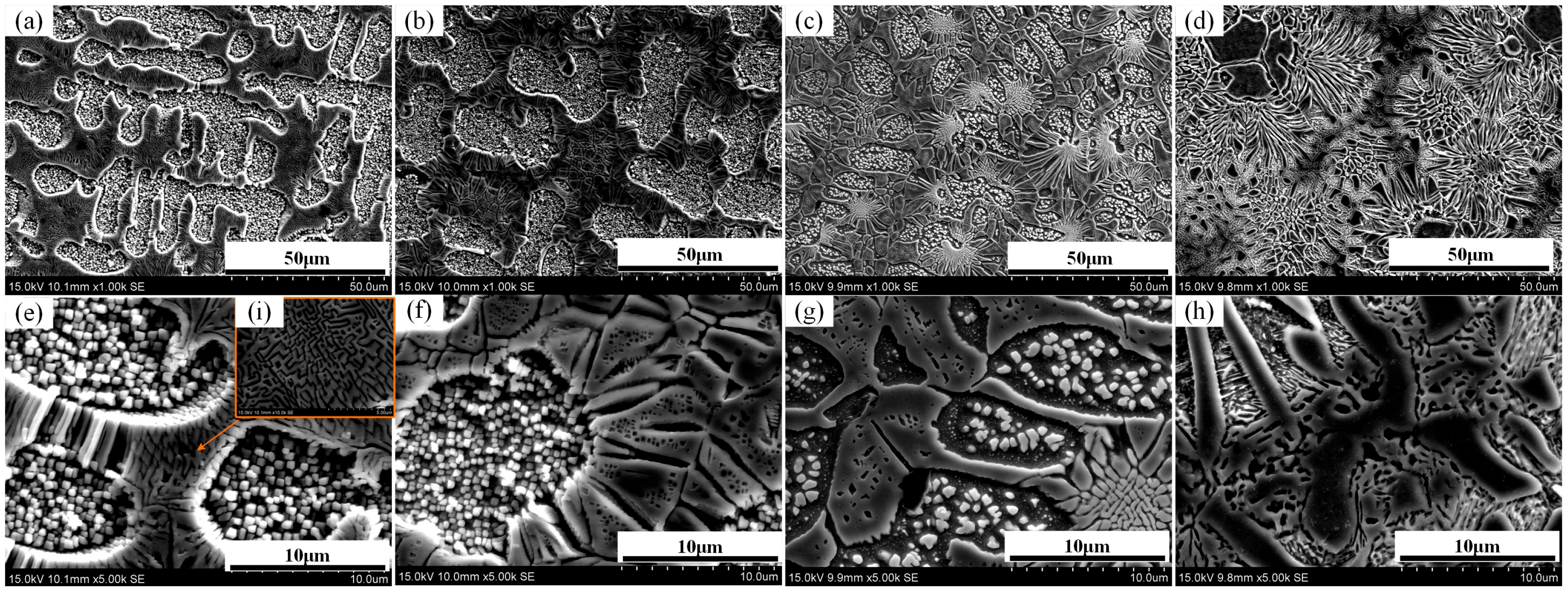
3.1. Microstructure Analysis

Figure 1 displays the microstructures of the various alloy samples. Figure 1a–d present the Si0–Si5 alloys at a magnification of 1000×, while Figure 1e–h show corresponding regions at 5000× magnification. Figure 1a,e reveal that the Si0 alloy exhibits a characteristic dendritic structure. A further magnified view of the dendritic zone (Figure 1i) shows a well-defined grid-like configuration, indicative of a modulated decomposition structure [56]. This structure arises from the uneven distribution of elements during solidification, where certain elements tend to enrich in specific regions, while others accumulate in adjacent zones, resulting in periodic compositional fluctuations. These periodic variations give rise to modulated microstructures. In high-entropy alloys, such structures are more prone to form due to the complex interactions among multiple principal elements and their relatively slow diffusion kinetics [56,57].
The phase analysis based on the XRD data is discussed in detail in our previous work [50], as shown in Figure 2. The Si0 alloy corresponds to a single BCC1 phase. Figure 1b,f illustrate that the Si1 alloy retains a dendritic morphology similar to that of Si0, but no grid-like modulated structures are observed within the dendrites. In Figure 1c,g, the Si3 alloy shows a transition to a chrysanthemum-like dendritic morphology, along with the appearance of particulate precipitates inside the dendritic grains. Both Si1 and Si3 consist of mixed BCC1 and BCC2 phases [50], and the analysis suggests that the addition of Si promotes the transformation from dendritic BCC1 to interdendritic BCC2 phases. Figure 1d,h indicate that the Si5 alloy exhibits an island-like grain configuration, in which the particulate features within the dendritic regions have disappeared. This microstructural evolution implies that the interdendritic phase observed in Si1 has transformed into the dendritic phase in the Si5 alloy. To further elucidate the phase constitution, compositional scans of the alloys were performed.
Figure 3 illustrates the elemental distributions obtained through area scanning for each alloy sample, while the actual elemental contents from the scanned regions are summarized in Table 2. As shown in Figure 3a, the dendritic regions of the Si0 alloy are deficient in Cr and Fe, while Cu is relatively uniformly distributed throughout the matrix. In contrast, the interdendritic areas are enriched in Cr and Fe. Figure 3b reveals a similar distribution pattern for the Si1 alloy, where the dendritic regions are mainly composed of Al and Ni, whereas Cr and Fe are concentrated in the interdendritic regions. In Figure 3c, compared to the Si1 alloy, Ni is more prominently concentrated in the dendritic zones of the Si3 alloy. Si appears to co-distribute with Fe and Cr, while the intermediate granular structures are primarily composed of Al and Ni phases. In Figure 3d, the island-like grains observed in the Si5 alloy mainly consist of Al and Ni, whereas the surrounding interdendritic regions are enriched in Fe and Cr. Unlike i Si3, Si in the Si5 alloy shows a stronger tendency to associate with Al and Ni. Across the Si1, Si3, and Si5 samples, Cu consistently tends to co-distribute with Al and Ni, suggesting a preferential segregation behavior.

3.2. Microhardness Analysis

Figure 4 presents the microhardness values of FeCrNiAl0.7Cu0.3Six HEAs with varying Si content. Figure 4b presents the microhardness values of FeCrNiAl0.7Cu0.3Six HEAs with varying Si content. A gradual increase in microhardness is observed, from 498.2 ± 15.0 HV for the Si0 sample to 502.7 ± 32.7 HV, 577.3 ± 24.5 HV, and 863.2 ± 23.5 HV for the Si1, Si3, and Si5 samples, respectively. The enhancement primarily stems from solid solution hardening combined with reinforcement from the second phase. As the Si content increases, more Si atoms dissolve into the matrix, substituting for other atoms or occupying interstitial sites. This leads to significant lattice distortion and generates local stress fields that hinder dislocation motion, thereby reducing dislocation mobility and limiting plastic deformation [20,58]. When the Si content reaches Si3, the solid solution strengthening effect becomes more pronounced, resulting in a marked increase in microhardness. Within the high-entropy matrix of the Si5 alloy, trace amounts of the σ phase are also generated. This hard, brittle secondary phase (σ phase) further impedes dislocation motion and contributes to the overall increase in microhardness [20].

3.3. Wear Analysis

Figure 5 shows the friction coefficient (COF) curves of FeCrNiAl0.7Cu0.3Six HEAs. All curves exhibit fluctuating behavior. For the Si0 sample, the COF shows a decreasing trend before 7 min, a peak around 10 min, and gradually stabilizes after 15 min. The Si1 sample shows a low point near 5 min, followed by a peak at 10 min, then stabilizes after 15 min. The Si3 sample remains relatively stable from the beginning of the test. The Si5 sample shows an increasing trend in the early stage and continues to fluctuate significantly even after 25 min. Overall, after 15 min, the COF tends to decrease with increasing Si content. The wear coefficients of each sample are shown in Figure 5.
Figure 6a displays the average friction coefficients of different samples, calculated over the period after 15 min of testing. The CoF of the Si0 alloy (0.571) is slightly higher than that of Si1 (0.551), while the CoF of the Si3 alloy (0.524) is significantly lower than those of Si0 and Si1. The Si5 alloy exhibits the lowest CoF at 0.468. It can be seen that alloys with higher Si content have lower COF. Figure 6b shows the wear mass of each sample, which are 1.31 mg, 1.28 mg, 1.11 mg, and 0.78 mg, and the trend is consistent with the wear coefficient. This reduction is consistent with the increasing microhardness, supporting the inverse relationship between microhardness and wear volume described by the Archard wear theory [59,60]. The Si5 alloy, with the highest microhardness, shows a 40.46% reduction in wear mass and a 19.61% decrease in friction coefficient compared to the Si0 sample. These improvements can be attributed to enhanced resistance against plastic deformation and the protective effect of hard secondary phases, which collectively reduce material removal during sliding wear.
Figure 7 shows the wear track of FeCoCrAl0.7Cu0.3Six high-entropy alloys, with corresponding 2D and 3D profiles at the wear track center, as well as a 2D cross-sectional view.
In comparison to the Si0 sample, the samples with Si exhibit shallower and narrower wear tracks in both width and depth. As shown in Figure 7a, the wear width and depth for Si0 are 993.4 μm and 53.7 μm, respectively. When the Si content is 0.1, the wear width and depth decrease to 798.2 μm and 47.2 μm (Figure 7b), and with a Si content of 0.3, the depth further reduces to 40.2 μm (Figure 7c). At Si5, the wear width and depth reach their lowest values of 616.2 μm and 18.9 μm, respectively. Compared to Si0, the wear width decreases by 37.9%, while the depth decreases by 64.8%.
Figure 8a,c,e,g depict the wear surface features of the Si0, Si1, Si3, and Si5 alloys, while the corresponding enlarged views are presented in (b), (d), (f), and (h), respectively. As the Si content increases, the wear surface and wear mechanisms gradually change. The wear surface of Si0 alloy exhibits consistent plowing grooves aligned with the wear direction, with white abrasive particles and block-like debris scattered around the grooves. The surface also shows delamination and plastic deformation at the edges. This type of damage is primarily caused by both abrasive wear and adhesive wear. The formation of the grooves is attributed to two factors: micro-cutting of the material surface by the abrasive particles and the formation of grooves under the frictional interaction. After repeated wear, the raised parts adjacent to the grooves gradually detach from the surface. The delamination phenomenon suggests that the shear strength of the adhesive points is greater than that of the alloy but less than the shear strength of WC, resulting in shear deformation on the alloy surface, which leads to a coexistence of abrasive wear and adhesive wear. The Si1 alloy surface still displays plowing grooves but without ridge-like protrusions, indicating that abrasive wear remains dominant, accompanied by some adhesive wear, with plastic deformation also occurring at the edges. The wear surface of Si3 alloy still shows primarily abrasive wear with the formation of granular abrasive agglomerates.
In contrast, the Si5 alloy surface is smoother, without visible grooves, and covered by lamellar debris. This is likely due to increased microhardness, which inhibits debris removal and promotes debris agglomeration. Under prolonged friction, local high temperatures may lead to cold welding and re-adhesion of debris to the surface. It should be noted that this interpretation does not consider possible adhesion to the WC counterbody. Therefore, the observed wear behavior may involve back-transfer effects, which require further investigation. Overall, Si addition alters the wear mechanism from abrasive to more adhesive in nature and enhances the wear resistance of the alloy, especially for the Si5 sample.

4. Conclusions

  • With increasing Si content, the microstructure changes from dendritic (Si0) to a transitional structure (Si1), then to chrysanthemum-like (Si3), and finally to island-like grains (Si5). Al and Ni are enriched in dendrites, while Cr and Fe are in interdendritic areas. Si and Cu tend to co-segregate with Al and Ni.
  • The microhardness of FeCrNiAl0.7Cu0.3Six alloys increases with rising Si content, from 484 HV for the Si0 alloy to 864 HV for the Si5 alloy. This enhancement is attributed to solid solution strengthening and the formation of the σ phase. The presence of secondary phase particles in Si3 and Si5 further contributes to mechanical strengthening.
  • The wear resistance is significantly improved with increasing Si. The wear mass decreases from 1.31 mg for the Si0 alloy to 0.78 mg for the Si5 alloy. Si0 and Si1 alloys primarily experience abrasive wear, whereas Si3 and Si5 exhibit smoother worn surfaces with layered wear debris, indicating a shift toward adhesive wear as the dominant mechanism. This transformation reflects the influence of Si on the alloy’s tribological behavior and provides insight into tailoring wear properties through composition design.
This study demonstrates that Si not only alters phase formation through thermodynamic interactions but also provides a practical route to optimize mechanical and wear performance in Fe-based high-entropy alloys.

Author Contributions

Software, X.H.; Data curation, J.L. (Jiaxin Liu); Writing—review & editing, J.L. (Junhong Li); Project administration, X.W.; Funding acquisition, Y.L. All authors have read and agreed to the published version of the manuscript.

Funding

This research was funded by 2024 Anhui Provincial University Scientific Research Project (Natural Science Category, Key Project, No. 2024AH052003); 2024 Provincial Department of Education Science and Engineering Teachers’ Internship Program in Enterprises (No. 2024jsqygz76); This study was supported by the High-level Talents Research Project of West Anhui University (Grant Nos. WGKQ2021068 and WGKQ2022058).

Institutional Review Board Statement

Not applicable.

Informed Consent Statement

Not applicable.

Data Availability Statement

Data is contained within the article.

Conflicts of Interest

The authors declare no conflicts of interest.

References

  1. Tong, C.J.; Chen, Y.L.; Chen, S.K.; Yeh, J.W.; Shun, T.T.; Tsau, C.H.; Lin, S.J.; Chang, S.Y. Microstructure characterization of AlxCoCrCuFeNi high-entropy alloy system with multiprincipal elements. Metall. Mater. Trans. A-Phys. Metall. Mater. Sci. 2005, 36A, 881–893. [Google Scholar] [CrossRef]
  2. Yeh, J.W.; Chen, S.K.; Lin, S.J.; Gan, J.Y.; Chin, T.S.; Shun, T.T.; Tsau, C.H.; Chang, S.Y. Nanostructured high-entropy alloys with multiple principal elements: Novel alloy design concepts and outcomes. Adv. Eng. Mater. 2004, 6, 299–303. [Google Scholar] [CrossRef]
  3. Li, D.X.; Liu, C.; Tao, S.S.; Cai, J.M.; Zhong, B.; Li, J.; Deng, W.T.; Hou, H.S.; Zou, G.Q.; Ji, X.B. High-Entropy Electrode Materials: Synthesis, Properties and Outlook. Nano-Micro Lett. 2025, 17, 22. [Google Scholar] [CrossRef] [PubMed]
  4. Xu, X.T.; Song, Z.; Wang, K.L.; Li, H.Q.; Pan, Y.; Hou, H.; Zhao, Y.H. Cryo-rolling and annealing-mediated phase transformation in Al5Ti2.5Fe25Cr25Ni42.5 high-entropy alloy: Experimental, phase-field and CALPHAD investigation. J. Mater. Sci. Technol. 2025, 219, 307–325. [Google Scholar] [CrossRef]
  5. Wang, J.M.; Jiang, H.; Xie, W.L.; Kong, X.; Qin, S.X.; Yao, H.W.; Li, Y. Effect of Mo addition on microstructural evolution and corrosion behaviors of AlCrFeNi3 eutectic high-entropy alloy. Corros. Sci. 2024, 229, 111879. [Google Scholar] [CrossRef]
  6. Charkhchian, J.; Zarei-Hanzaki, A.; Schwarz, T.M.; Lawitzki, R.; Schmitz, G.; Schell, N.; Shen, J.J.; Oliveira, J.P.; Waryoba, D.; Abedi, H.R. Unleashing the microstructural evolutions during hot deformation of as-cast AlCoCrFeNi2.1 eutectic high entropy alloy. Intermetallics 2024, 168, 108253. [Google Scholar] [CrossRef]
  7. Zhang, Z.K.; Hua, K.; Cao, Y.; Song, Y.Q.; Li, X.L.; Zhou, Q.; Wang, H.F. Microstructures and properties of FeCrAlMoSix high entropy alloy coatings prepared by laser cladding on a titanium alloy substrate. Surf. Coat. Technol. 2024, 478, 130437. [Google Scholar] [CrossRef]
  8. Feng, Y.; Shi, X.J.; Lu, X.Q.; Sun, W.; Liu, K.P.; Fei, Y.F. Predictions of friction and wear in ball bearings based on a 3D point contact mixed EHL model. Surf. Coat. Technol. 2025, 502, 131939. [Google Scholar] [CrossRef]
  9. Shen, J.J.; Choi, Y.T.; Yang, J.; He, J.J.; Zeng, Z.; Zhou, N.; Baptista, A.C.; Kim, H.S.; Oliveira, J.P. Fabrication of spatially-variable heterostructured CoCrFeMnNi high entropy alloy by laser processing. Mater. Sci. Eng. A-Struct. Mater. Prop. Microstruct. Process. 2024, 896, 146272. [Google Scholar] [CrossRef]
  10. Li, Z.; Zhao, W.; Yu, K.D.; Guo, N.; Xiao, G.C.; Wang, Z.M.; Zhang, H. Effect of Y2O3 on microstructure and properties of CoCrFeNiTiNb high entropy alloy coating on Ti-6Al-4V surface by laser cladding. J. Rare Earths 2024, 42, 586–599. [Google Scholar] [CrossRef]
  11. Zhu, B.; Wang, Z.; Zhang, Y.; Yu, Z.; Shi, J.; Xiong, R. Low temperature fabrication of the giant dielectric material CaCu3Ti4O12 by oxalate coprecipitation m ethod. Mater. Chem. Phys. 2009, 113, 746–748. [Google Scholar] [CrossRef]
  12. Zhu, B.-P.; Tang, Z.; Zhao, L.-H.; Wang, L.-L.; Li, C.-Z.; Yin, D.; Yu, Z.-X.; Tang, W.-F.; Xiong, R.; Shi, J.; et al. Synthesis of Mg[Ti2]O4 by spark plasma sintering. Mater. Lett. 2007, 61, 578–581. [Google Scholar] [CrossRef]
  13. Li, Z.Y.; Wang, X.H.; Huang, Y.Y.; Xu, Z.X.; Deng, Y.L.; Jiang, X.Y.; Yang, X.H. Microstructure, Mechanical Property, and Wear Behavior of NiAl-Based High-Entropy Alloy. Coatings 2023, 13, 1737. [Google Scholar] [CrossRef]
  14. Zheng, W.J.; Lu, S.L.; Wu, S.S.; Chen, X.H.; Guo, W. Development of MoNbVTx refractory high entropy alloy with high strength at elevated temperature. Mater. Sci. Eng. A-Struct. Mater. Prop. Microstruct. Process. 2022, 850, 143554. [Google Scholar] [CrossRef]
  15. Zhang, H.Z.; Zhu, Z.B.; Huang, H.F.; He, T.; Yan, H.W.; Zhang, Y.A.; Lu, Y.P.; Wang, T.M.; Li, T.N.G. Microstructures, mechanical properties, and irradiation tolerance of the Ti-Zr-Nb-V-Mo refractory high-entropy alloys. Intermetallics 2023, 157, 107873. [Google Scholar] [CrossRef]
  16. Gong, P.; Wang, D.L.; Zhang, C.; Wang, Y.; Jamili-Shirvan, Z.; Yao, K.F.; Wang, X.Y. Corrosion behavior of TiZrHfBeCu(Ni) high-entropy bulk metallic glasses in 3.5 wt. % NaCl. NPJ Mater. Degrad. 2022, 6, 77. [Google Scholar] [CrossRef]
  17. Yu, K.D.; Zhao, W.; Li, Z.; Guo, N.; Xiao, G.C.; Zhang, H. High-temperature oxidation behavior and corrosion resistance of in-situ TiC and Mo reinforced AlCoCrFeNi-based high entropy alloy coatings by laser cladding. Ceram. Int. 2023, 49, 10151–10164. [Google Scholar] [CrossRef]
  18. Wen, X.; Cui, X.F.; Jin, G.; Liu, Y.F.; Zhang, Y.; Zhang, X.R.; Liu, E.B.; Tian, H.L.; Fang, Y.C. Corrosion and tribo-corrosion behaviors of nano-lamellar Ni1.5CrCoFe0.5Mo0.1Nbx eutectic high-entropy alloy coatings: The role of dual-phase microstructure. Corros. Sci. 2022, 201, 110305. [Google Scholar] [CrossRef]
  19. Ju, Y.; Konoplianchenko, I.; Pu, J.F.; Zhang, Z.C.; Dong, Q.; Dumanchuk, M. Optimization of structure and properties of WC-reinforced FeCoNiCr high-entropy alloy composite coating by laser melting. Results Eng. 2024, 21, 101985. [Google Scholar] [CrossRef]
  20. Lin, T.; Feng, M.; Lian, G.; Lu, H.; Chen, C.; Huang, X. Effects of Si content on the microstructure and properties of CoCrFeMnNiSix high-entropy alloy coatings by laser cladding. Mater. Charact. 2024, 216, 114246. [Google Scholar] [CrossRef]
  21. Liu, G.L.; Xu, D.; Yang, H.Y.; Liu, F.X.; Wang, B.P.; Wang, L.; Guo, X.; Sui, M.B.; Wang, L.; Xue, Y.F. Tailoring the non-coherent interfacial precipitation to overcome the trade-off between strength-ductility and impact energy release in Ti-Zr-Hf-Nb-Ta high entropy alloy. Intermetallics 2024, 166, 108194. [Google Scholar] [CrossRef]
  22. Ward, T.Z.; Wilkerson, R.P.; Musicó, B.L.; Foley, A.; Brahlek, M.; Weber, W.J.; Sickafus, K.E.; Mazza, A.R. High entropy ceramics for applications in extreme environments. J. Phys.-Mater. 2024, 7, 021001. [Google Scholar] [CrossRef]
  23. Liu, W.; Wang, C.T.; Zhao, S.C.; Chen, L.; Li, Y.T.; Jiang, X.; Leng, Y.X. Enhancing wear resistance: In-situ ceramic phase precipitation for strengthening and toughening FeCoNiCrNx high-entropy alloy films. Surf. Coat. Technol. 2024, 478, 130466. [Google Scholar] [CrossRef]
  24. Ali, S.; Ahmed, M.; Liu, B.Y.; Balal, A.H.; Jia, Y.F.; Tariq, N.H.; Sun, K.; Mu, Y.K.; Jia, Y.D.; Wang, G. Microstructural stability and mechanical property of AlCrFeMoTi high-entropy amorphous alloy thin films under He plus ions irradiation. Surf. Coat. Technol. 2024, 487, 130952. [Google Scholar] [CrossRef]
  25. Wang, J.C.; Man, J.; Wang, Q.T.; Liu, G.G.; Xiao, S.C.; Dong, N. Effect of Nano WC on Wear and Corrosion Resistances of CoCrFeNiTi High Entropy Alloy Coating. J. Mater. Eng. Perform. 2025, 34, 1078–1087. [Google Scholar] [CrossRef]
  26. Valiev, R.R.; Oleinik, A.V.; Asfandiyarov, R.N.; Nazarov, A.Y.; Ramazanov, K.N.; Savina, Y.N.; Kilmametov, A.R. Mathematical Modeling of Complex-Shape Forming of Ultrafine-Grained Ti Alloy and Subsequent Deposition of Protective High-Entropy Coatings. Phys. Mesomech. 2024, 27, 725–735. [Google Scholar] [CrossRef]
  27. Liu, Q.; Li, X.G.; Wang, G.F.; Zhu, J.; Zhan, R.; Liu, Y.K.; Guan, W.; Liang, H.; Cui, L.; Liu, Y.C. Deformation-induced grain boundary segregation in a powder-metallurgy ultrafine-grained MoNbTaTiV refractory high-entropy alloy. Heliyon 2024, 10, e37392. [Google Scholar] [CrossRef]
  28. Yurchenko, N.; Panina, E.; Tojibaev, A.; Novikov, V.; Salishchev, G.; Zherebtsov, S.; Stepanov, N. Tuning the grain and domain sizes to achieve superior room-temperature tensile ductility in a B2-ordered refractory Al15Nb40Ti40V5 medium-entropy alloy. Mater. Sci. Eng. A-Struct. Mater. Prop. Microstruct. Process. 2023, 874, 145073. [Google Scholar] [CrossRef]
  29. Wang, W.Q.; Qu, L.D.; Lu, Y.Z. Effect of heat treatment on microstructure and mechanical properties of lightweight high-entropy alloy. J. Alloys Compd. 2024, 1008, 176219. [Google Scholar] [CrossRef]
  30. Chen, Y.W.; Zheng, J.Y.; Xu, Z.Q.; Cheng, B.; Li, Y.K.; Zhang, J. A lightweight TiZrV0.5Nb0.3Al0.2 refractory high-entropy alloys with enhanced strength and ductility at low and high strains loading. Mater. Sci. Eng. A-Struct. Mater. Prop. Microstruct. Process. 2025, 922, 147653. [Google Scholar] [CrossRef]
  31. Shen, J.J.; Gonçalves, R.; Choi, Y.T.; Lopes, J.G.; Yang, J.; Schell, N.; Kim, H.S.; Oliveira, J.P. Microstructure and mechanical properties of gas metal arc welded CoCrFeMnNi joints using a 410 stainless steel filler metal. Mater. Sci. Eng. A-Struct. Mater. Prop. Microstruct. Process. 2022, 857, 144025. [Google Scholar] [CrossRef]
  32. Liu, H.; Gao, Q.; Dai, J.B.; Chen, P.J.; Gao, W.P.; Hao, J.B.; Yang, H.F. Microstructure and high-temperature wear behavior of CoCrFeNiWx high-entropy alloy coatings fabricated by laser cladding. Tribol. Int. 2022, 172, 107574. [Google Scholar] [CrossRef]
  33. Yuan, G.; Pestana, L.R. The Effect of Surface Oxygen Coverage on the Oxygen Evolution Reaction over a CoFeNiCr High-Entropy Alloy. Nanomaterials 2024, 14, 1058. [Google Scholar] [CrossRef] [PubMed]
  34. Xu, S.Y.; Hong, L.; Wu, S.Y.; Qin, Y.; Yang, S.; Huang, M. Effect of transition-metals (Fe, Co and Ni) on the L12-phase strengthening in the Al0.3CrFeCoNi high-entropy alloy. Intermetallics 2024, 166, 108206. [Google Scholar] [CrossRef]
  35. Song, J.F.; Chai, Z.S.; Zheng, J.; Wu, Q.F.; He, F.; Yang, Z.N.; Li, J.J.; Wang, J.C.; Yang, H.O.; Wang, Z.J. Design Fe-based Eutectic Medium-Entropy Alloys Fe2NiCrNbx. ACTA Metall. Sin.-Engl. Lett. 2021, 34, 1103–1108. [Google Scholar] [CrossRef]
  36. Li, Y.; Jiang, X.; Wang, X.; Leng, Y. Integration of hardness and toughness in (CuNiTiNbCr)Nx high entropy films through nitrogen-induced nanocomposite structure. Scr. Mater. 2024, 238, 115763. [Google Scholar] [CrossRef]
  37. Zhu, B.P.; Guo, W.K.; Shen, G.Z.; Zhou, Q.; Shung, K.K. Structure and electrical properties of (111)-oriented Pb(Mg1/3Nb2/3)O3-PbZrO3-PbTiO3 thin film for ultra-high-frequency transducer applications. IEEE Trans. Ultrason. Ferroelectr. Freq. Control. 2011, 58, 1962–1967. [Google Scholar] [CrossRef]
  38. Kao, Y.-F.; Chen, T.-J.; Chen, S.-K.; Yeh, J.-W. Microstructure and mechanical property of as-cast, -homogenized, and -deformed AlxCoCrFeNi (0 ≤ x ≤ 2) high-entropy alloys. J. Alloys Compd. 2009, 488, 57–64. [Google Scholar] [CrossRef]
  39. Yang, X.C.; Li, X.M. Research on the synergistic damage behavior of tribocorrosion of CoCrFeNi-X (Ti, Mn, Mo, Al) high-entropy alloys. Tribol. Int. 2025, 201, 110185. [Google Scholar] [CrossRef]
  40. Wu, M.; Setiawan, R.C.; Li, D.Y. Benefits of passive element Ti to the resistance of AlCrFeCoNi high-entropy alloy to corrosion and corrosive wear. Wear 2022, 492–493, 204231. [Google Scholar] [CrossRef]
  41. Hsu, C.-Y.; Sheu, T.-S.; Yeh, J.-W.; Chen, S.-K. Effect of iron content on wear behavior of AlCoCrFexMo0.5Ni high-entropy alloys. Wear 2010, 268, 653–659. [Google Scholar] [CrossRef]
  42. Song, M.; Zhou, R.; Gu, J.; Wang, Z.; Ni, S.; Liu, Y. Nitrogen induced heterogeneous structures overcome strength-ductility trade-off in an additively manufactured high-entropy alloy. Appl. Mater. Today 2020, 18, 100498. [Google Scholar] [CrossRef]
  43. Lei, Z.; Liu, X.; Wu, Y.; Wang, H.; Jiang, S.; Wang, S.; Hui, X.; Wu, Y.; Gault, B.; Kontis, P.; et al. Enhanced strength and ductility in a high-entropy alloy via ordered oxygen complexes. Nature 2018, 563, 546–550. [Google Scholar] [CrossRef] [PubMed]
  44. Xiong, F.; Fu, R.; Li, Y.; Xu, B.; Qi, X. Influences of nitrogen alloying on microstructural evolution and tensile properties of CoCrFeMnNi high-entropy alloy treated by cold-rolling and subsequent annealing. Mater. Sci. Eng. A 2020, 787, 139472. [Google Scholar] [CrossRef]
  45. Zhu, J.M.; Fu, H.M.; Zhang, H.F.; Wang, A.M.; Li, H.; Hu, Z.Q. Synthesis and properties of multiprincipal component AlCoCrFeNiSix alloys. Mater. Sci. Eng. A 2010, 527, 7210–7214. [Google Scholar] [CrossRef]
  46. Guo, W.; Li, J.; Qi, M.; Xu, Y.; Ezatpour, H.R. Effects of heat treatment on the microstructure, wear behavior and corrosion resistance of AlCoCrFeNiSi high-entropy alloy. Intermetallics 2021, 138, 107324. [Google Scholar] [CrossRef]
  47. Li, Y.Z.; Shi, Y. Microhardness, wear resistance, and corrosion resistance of AlxCrFeCoNiCu high-entropy alloy coatings on aluminum by laser cladding. Opt. Laser Technol. 2021, 134, 106632. [Google Scholar] [CrossRef]
  48. Li, Y.Z.; Shi, Y.; Chen, R.N.; Wang, H.X.; Zhang, P.; Zhou, B.J.; Li, D.F.; Lin, H.; Ding, L. Influence of Al content on the elastic properties and various anisotropies of AlxCrFeCoNiCu high entropy alloys base on the first-principles calculation. Mater. Res. Express 2023, 10, 066505. [Google Scholar] [CrossRef]
  49. Xi, R.; Li, Y.Z. Influence of Si Content on the Microstructure, Wear Resistance, and Corrosion Resistance of FeCoNiCrAl0.7Cu0.3Six High Entropy Alloy. Coatings 2024, 14, 1309. [Google Scholar] [CrossRef]
  50. Shi, X.; Liang, H.; Li, Y. Effect of Si Content on Phase Structure, Microstructure, and Corrosion Resistance of FeCrNiAl0.7Cu0.3Six High-Entropy Alloys in 3.5% NaCl Solution. Coatings 2025, 15, 342. [Google Scholar] [CrossRef]
  51. Wu, H.; Zhang, S.; Wang, Z.Y.; Zhang, C.H.; Chen, H.T.; Chen, J. New studies on wear and corrosion behavior of laser cladding FeNiCoCrMox high entropy alloy coating: The role of Mo. Int. J. Refract. Met. Hard Mater. 2022, 102, 105721. [Google Scholar] [CrossRef]
  52. Hajilou, N.; Javaheri, M.; Ebadzadeh, T.; Farvizi, M. Investigation of the electrochemical behavior of AlCoCrFeNi-ZrO2 high entropy alloy composites prepared with mechanical alloying and spark plasma sintering. J. Appl. Electrochem. 2024, 54, 457–466. [Google Scholar] [CrossRef]
  53. Sekhar, R.A.; Shifin, A.S.; Firoz, N. Microstructure and mechanical properties of AlCoCrNiTi-C High Entropy Alloy processed through Spark Plasma Sintering. Mater. Chem. Phys. 2021, 270, 124846. [Google Scholar] [CrossRef]
  54. Li, M.; Gazquez, J.; Borisevich, A.; Mishra, R.; Flores, K.M. Evaluation of microstructure and mechanical property variations in AlxCoCrFeNi high entropy alloys produced by a high-throughput laser deposition method. Intermetallics 2018, 95, 110–118. [Google Scholar] [CrossRef]
  55. Chaudhary, V.; Soni, V.; Gwalani, B.; Ramanujan, R.V.; Banerjee, R. Influence of non-magnetic Cu on enhancing the low temperature magnetic properties and Curie temperature of FeCoNiCrCu(x) high entropy alloys. Scr. Mater. 2020, 182, 99–103. [Google Scholar] [CrossRef]
  56. Zhang, Y.; Chen, Z.; Cao, D.D.; Zhang, J.Y.; Zhang, P.; Tao, Q.; Yang, X.Q. Concurrence of spinodal decomposition and nano-phase precipitation in a multi-component AlCoCrCuFeNi high-entropy alloy. J. Mater. Res. Technol.-JMRT 2019, 8, 726–736. [Google Scholar] [CrossRef]
  57. Hussain, M.; Najib, A.S.M.; Fadil, N.A.; Bakar, T.A.A. Microstructure and Phase Chemistry of Vacuum Induction Melting Fabricated-Equimolar AlCoCrFeNi HEA During Spinodal Dissolution Annealing. Int. J. Integr. Eng. 2024, 16, 145–153. [Google Scholar] [CrossRef]
  58. Liu, H.; Zhang, T.; Sun, S.; Zhang, G.; Tian, X.; Chen, P. Microstructure and dislocation density of AlCoCrFeNiSix high entropy alloy coatings by laser cladding. Mater. Lett. 2021, 283, 128746. [Google Scholar] [CrossRef]
  59. Zhu, B.P.; Wu, D.W.; Zhou, Q.F.; Shi, J.; Shung, K.K. Lead zirconate titanate thick film with enhanced electrical properties for high frequency transducer applications. Appl. Phys. Lett. 2008, 93, 012905. [Google Scholar] [CrossRef]
  60. Feng, L.; Yang, Y.; Zhao, Y.; Ma, K.; Cui, J. Corrosion behaviors and mechanism of AlxCrFeMnCu high-entropy alloys in a 3.5 wt% NaCl solution. Corros. Sci. 2024, 233, 112087. [Google Scholar] [CrossRef]
Figure 1. SEM microstructures of FeCrNiAl0.7Cu0.3Six HEAs with different Si content: (a,e,i) Si0 alloy; (b,f) Si1; (c,g) Si3; (d,h) Si5.
Coatings 15 00676 g001
Figure 2. The XRD of FeCrNiAl0.7Cu0.3Six HEAs.
Coatings 15 00676 g002
Figure 3. EDS elemental mapping images of FeCrNiAl0.7Cu0.3Six alloys (a) Si0, (b) Si1, (c) Si3, (d) Si5 alloy.
Coatings 15 00676 g003
Figure 4. Microhardness values of FeCrNiAl0.7Cu0.3Six HEAs (x = 0, 0.1, 0.3, 0.5) (a) Hardness test results; (b) Indentation morphology.
Coatings 15 00676 g004
Figure 5. The COF for FeCrNiAl0.7Cu0.3Six HEAs (x = 0, 0.1, 0.3, 0.5).
Coatings 15 00676 g005
Figure 6. Friction and wear properties of FeCoCrAl0.7Cu0.3Six HEAS with different Si contents: (a) COF; (b) wear mass.
Coatings 15 00676 g006
Figure 7. Wear track characterization of FeCoCrAl0.7Cu0.3Six HEAs: macroscopic morphology, laser confocal topography, and geometric profile for (a) Si0, (b) Si1, (c) Si3, (d) Si5 alloy.
Coatings 15 00676 g007
Figure 8. Worn surface characteristics of FeNiCrAl0.7Cu0.3Six HEAs: (a,b) Si0, (c,d) Si1, (e,f) Si3, (g,h) Si5 alloy.
Coatings 15 00676 g008
Table 1. Nominal components of FeNiCrAl0.7Cu0.3Six HEAs (at%).
AlloyAbbreviationFeNiCrAlCuSi
FeNiCrAl0.7Cu0.3Si025.0025.0025.0017.507.500.00
FeNiCrAl0.7Cu0.3Si0.1Si124.3924.3924.3917.077.322.44
FeNiCrAl0.7Cu0.3Si0.3Si323.2623.2623.2616.286.986.98
FeNiCrAl0.7Cu0.3Si0.5Si522.2222.2222.2215.566.6711.11
Table 2. Actual elemental compositions obtained from area scanning of FeCrNiAl0.7Cu0.3Six alloys.
AlloyAbbreviationFeNiCrAlCuSi
FeNiCrAl0.7Cu0.3Si012.6340.468.1825.6513.080.00
FeNiCrAl0.7Cu0.3Si0.1Si116.1835.9913.4622.3411.230.80
FeNiCrAl0.7Cu0.3Si0.3Si316.7926.4722.3816.797.644.91
FeNiCrAl0.7Cu0.3Si0.5Si524.8027.3217.0117.018.185.87
Disclaimer/Publisher’s Note: The statements, opinions and data contained in all publications are solely those of the individual author(s) and contributor(s) and not of MDPI and/or the editor(s). MDPI and/or the editor(s) disclaim responsibility for any injury to people or property resulting from any ideas, methods, instructions or products referred to in the content.

